O2PH2 - Security Camera Speco Technologies - Free user manual and instructions
Find the device manual for free O2PH2 Speco Technologies in PDF.

User questions about O2PH2 Speco Technologies
0 question about this device. Answer the ones you know or ask your own.
Ask a new question about this device
Download the instructions for your Security Camera in PDF format for free! Find your manual O2PH2 - Speco Technologies and take your electronic device back in hand. On this page are published all the documents necessary for the use of your device. O2PH2 by Speco Technologies.
USER MANUAL O2PH2 Speco Technologies
Network Camera Web Setup Manual
Table of Contents
1 Connection and Login....1
1.1 Network Connection....1
1.2 Log in....1
2 Live View 3
2.1 Stream Setup 3
2.2 >unction Menu....4
2.3 Live View Display Adjustment 5
2.3.1 Image Adjustment ....5
2.3.2 Original Size 6
2.3.3 >ull Screen....6
2.3.4 Width and +eight Ratio 6
2.3.5 >luency Adjustment....6
2.3.6 Rules Info 6
2.3.7 Zoom and >ocus....6
2.4 >isheye Live View....8
3 PTZ Control 9
3.1 Scan/Tour/Pattern/Pan 10
3.2 Preset....10
3.3 Go To....11
4 Playback....12
4.1 Playback....12
4.1.1 Play Controls....13
4.1.2 Playback >ile 14
4.1.3 Playback Cut....16
4.1.4 Record Type....16
4.1.5 Progress Bar....16
5.2.4 DDNS Client....37
5.2.5 IP >iltering....37
5.2.6 SMTP (Email) 38
5.2.7 %PnP 39
5.2.8 SNMP 40
5.2.9 Multicast 42
5.2.10 802.1x 43
5.2.11 <oS....43
5.2.12 +TTPs 44
5.3 Event Setup....53
5.3.1 Video detection 53
5.3.2 Audio Detection....56
5.3.3 Smart Plan....59
5.3.4 Intelligent Video 59
5.3.5 >ace Detection....65
5.3.6 +eat Map 66
5.3.7 Alarm....69
5.3.8 Abnormality....69
5.4 Storage Management....72
5.4.1 Schedule....72
5.4.2 Destination 74
5.4.3 Record control 77
5.5 System....78
5.5.1 General 78
5.5.2 %ser Admin 80
5.5.3 >actory Default 83
5.5.4 Import/Export....83
5.5.5 %grade 84
Note
The instructions in this manual apply to the following models.
- O2PH2
• O3VLD1
• O3VLB3
• O3VFDM
• O3VFBM
• O4D1
• O4B7
• O4D2M - O4B2M
• O6MDP2
• O8D2M
• O8B2M - O2P4X
• O2P12X
• O4P30X
1 Connection and Login
1.1 Network Connection
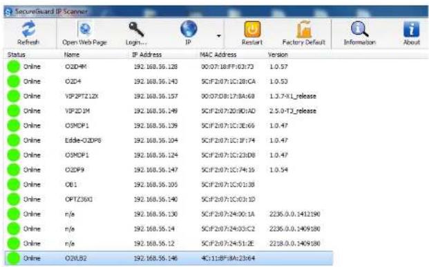
Connect the camera to a network and run the IP Scanner tool7 IP Scanner can search for the device on the local network7The camera is set to D+CP mode by default7
Open up IP Scanner7In the device list, you can view the IP address, model number, and MAC address of each device7 Select the applicable device and double click to open up the web viewer
See >igure 1-17
text_image
SecureGuard IP Scanner Refresh Open Web Page Login... IP Restart Factory Default Information About Status None IP Address MAC Address Version Online O2D4M 192.168.36.128 00:07:18:FF:02:73 1.0.57 Online O2D4 192.168.36.143 5CIF:20:7:1C:28:CA 1.0.53 Online VSP2PTZ1ZX 192.168.36.157 00:07:D8:17:BA:68 1.3.7-XL_release Online VSP2D 1M 192.168.36.149 5CIF:20:7:20:90:AD 2.5.0-T2_release Online O3MOP1 192.168.36.139 5CIF:20:7:1C:3E:65 1.0.47 Online Eddie-O2DP6 192.168.36.104 5CIF:20:7:1C:1F:74 1.0.47 Online O3MOP1 192.168.36.124 5CIF:20:7:1C:23:D8 1.0.47 Online O2DP9 192.168.36.147 5CIF:20:7:1C:74:16 1.0.54 Online OB1 192.168.36.105 5CIF:20:7:1C:01:38 Online OPTZ3XG 192.168.36.140 5CIF:20:7:1C:03:1D Online n/e 192.168.36.130 5CIF:20:7:24:00:1A 2235.0.0.1412190 Online n/e 192.168.36.14 5CIF:20:7:24:03:C2 2235.0.0.1499180 Online n/e 192.168.36.12 5CIF:20:7:24:51:2E 2235.0.0.1499180 Online O2VLB2 192.168.36.146 4C:11:B*8:A:23:E/4figure 1-1

text_image
speco technologies Username: Password: Login Canceligure 1-2
There will be a prompt shown to recommend changing the default password7 >or direct connection installations on Speco's plug and play NVRs with built-in PoE ports, please leave the password as default7 >or other installations, it is highly recommended to change the password for security purposes7

text_image
For security purposes, it is recommended to change the password. New Password Weak OK Strong2 Live View
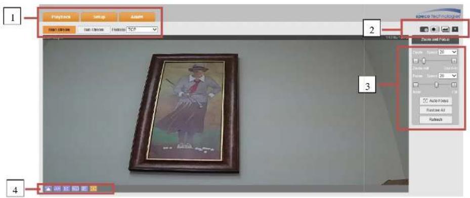
After logging in, the live view screen will be shown 7 See >igure 2-17
text_image
Playback Setup Assim RGB: 100% RGB: 100% RGB: 100% RGB: 100% RGB: 100% RGB: 100% RGB: 100% RGB: 100% RGB: 100% RGB: 100% RGB: 100% RGB: 100% RGB: 100% RGB: 100% RGB: 100% RGB: RGB RGB RGB RGB RGB RGB RGB RGB RGB RGB RGB RGB RGB RGB RGB RGB RGB RGB RGB RGB RGB RGB RGB RGB RGB RGB RGB RGB RGB RGB RGB RGB RGB RGB RGB RGB RGB RGB RGB RGB RGB RGB RGB RGB RGB RGB RGB RGB RGB RGB RGBigure 2-1
There are four sections:
● Section 1: System menu and stream selection
- Section 2: >unction menu 6snapst ot, digital zoom, etc;
● Section 9: PTZ and zoom control menu 6optional
● Section 4: Live view display adjustment controls
7.1 Classroom Setting
Please refer to the following table for detailed information7
| Parameter | >unction |
| Main stream | Click it to enable main stream video monitoring and click again to disable it7 |
| Sub Stream 1 | Click it to enable Sub Stream1 video monitoring and click again to disable it7 |
| Sub Stream 2 | Click it to enable Sub Stream 2 video monitoring and click again to disable it7 |
| Protocol | You can select the streaming protocol from the dropdown lis:7There are three options: TCP/%DP/MulticastTCP is the default: |
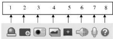
2.2 Function Menu
The function menu interface is shown in >igure 2-97
text_image
1 2 3 4 5 6 7 8igure 2-9
Please refer to the following table for detailed information7
| Parameter | >unction |
| 1 Relay-out | If there is alarm output, status description is as follows:● Red: means there is alarm output? |
| 5 Easy focus | Displays two parameters for focusing: A> Peak and A> Max.A> Peak: Displays the video definition during the focus process.A> Max: optimal value for video definition.The closer A> Peak and A> Max are to each other, the better the focus effect is. | |
| 7 Audio | Toggle audio. | |
| 8 Talk | Toggle push to talk. | |
| 9 +elp | Opens the help window. |
2.3Live View Display Adjustment
The interface is shown as in >igure 2-4.

igure 2-4
2.3.1 Image Adjustment
See >igure 2-5 for image adjustment.

Please refer to the following table for detailed information.
| Parameter Function | |||
| Video setup | [1472] | Brightness | Note:● All operations here apply to web live view only.● Please go to Setup -> Basic Setup -> Image Setup to adjust the parameters on the camera itself. |
| [2444] | Contrast | ||
| [597C] | Hue | ||
| [3210] | Saturation | ||
| Reset | Restore to system default setup. | ||
2.3.2 Original Size
Click this button to display the actual resolution size of the stream.
2.3.3 Full Screen
Click to go to full-screen mode. Double click the mouse or press the Esc button on the keyboard to exit full screen.
2.3.4 Width and Height Ratio
Click to display in the original ratio or fill the display window.
2.3.5 Fluency Adjustment
Depending on the network bandwidth, priority could be given to how the stream is delivered. The fluency mode

text_image
Zoom and Focus Zoom Speed 20 Zoom out Zoom in Focus Speed 20 Near Far Auto Focus Restore All Refreshigure 2-6
| Parameterdd | >unctiond |
| Zoom | Adjust the focal length of the lens by clicking or long pressing "+" -"buttons.Speed is used to adjust the length of one step for a single click. |
| >ocus | Adjust the focus by clicking or long pressing "+"、 "-" buttons.Speed is used to adjust the length of one step for a single click. |
| Auto-focus | Click to adjust the focus automatically.Note:Other lens operations are not allowed during this process. |
2.4 Fisheye Live View
This section applies to O6MDP2 only. In live view, the interface shown in >figure 2-7 will be shown on the right side of the window.

text_image
Install Mode Display Modeigure 2-7
Note: The dewarping modes shown here in live view only affects what's being seen in the web viewer only. To change the actual dewarped mode of the stream itself, it must be first configured in Setup. See section 5.1.1.7.
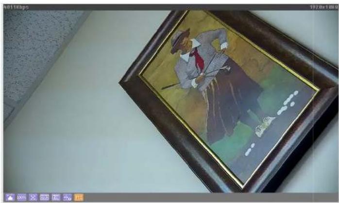
3 PTZ Control
See
natural_image
Illustration of a man in a hat and red tie holding a cane, framed in a dark frame (no text or symbols visible)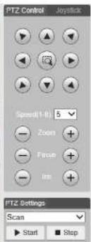
text_image
PTZ Control Joystick Speed(1-8): 5 Zoom Fuse Im FTZ Settings Scan Start Stopigure 9-1 for PTZ controls7
| Parameter Note | |
| PTZ direction | ● PTZ supports eight directions: left/right/up/down/upper left/upper right/bottom left/bottom right; |
| Speed | The higher the value, higher the speed7 Applies to pan, tilt,zoom, focus and iris7 |
| %se mouse to draw a box of interest in the image7 The camera will rotate and zoom |
natural_image
Illustration of a man in a hat and tie holding a cane, framed with a dark wooden frame (no text or symbols visible)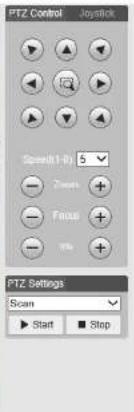
text_image
PTZ Control Joystick Spread1-Ri 5 Zoom Focus Stop PTZ Settings Scan Start Stopigure 9-1
PTZ settings interface is shown in >igure 9-27
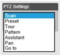
igure 9-2
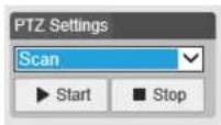
3.1 Scan/Tour/Pattern/Pan
The interface is shown in >igure 9-97 Enter applicable values for tour and pattern7. Click on start to begin the function and stop to end the function7
igure 9-9
3.2 Preset
Preset interface is shown in >igure 9-47 Enter the preset value and press Go to7

3.3 Go To
Go to interface is shown in >figure 9-57 Enter the horizontal angle, vertical angle, and zoom position to go to that exact position?

text_image
PTZ Settings Go to Horizontal Angle(0~3600) 0 Vertical Angle(0~900) 0 Zoom(1~128) 1 Go toigure 9-5
4 Playback
Recordings on the SD card can be accessed through the web browser;
Note
Before playback, the SD card must be properly installed and configured? Refer to section 574for detailed Instructions7
4.1 Playback
The SD card playback interface is shown in >igure 4-17

text_image
Speed Technologies File Type: 027 Speed: 500000 Age: 2917 Run Man Tree Work Time: 16:30 OK: 100% OK: 100% OK Speed Type: Normal Event Action Name: Play Play Play Closeigure 4-1
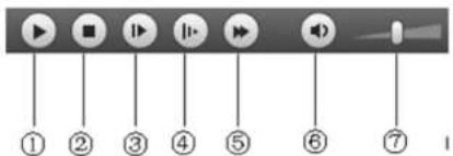
4.1.1 Play Controls
The control functions are shown in >igure 4-2 and >igure 4-97

text_image
① ② ③ ④ ⑤ ⑥ ⑦igure 4-2
text_image
① ② ③ ④ ⑤ ⑥ ⑦igure 4-9
| Parameter Function | |
| 1 Play | Press to start playing |
| 2 Stop | Press to stop playing |
| 3 Play by frame | Press to go to the next frame7Note:Recording will be paused while this function is in use7 |
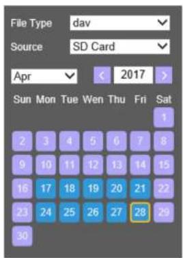
4.1.2 Playback File
In the calendar, dates highlighted blue have recorded data7 See >igure 4-47
text_image
File Type: dav Source: SD Card Apr < 2017 > Sun Mon Tue Wen Thu Fri Sat 2 3 4 5 6 7 8 9 10 11 12 13 14 15 16 17 18 19 20 21 22 23 24 25 26 27 28 29 30igure 4-4
| Parameter Function | |
| >ile Type | Select "dav" for video playback7Select "jpg" for picture playback7 |
| Data Source | Default is SD card7 |
Step 17 Click on a date highlighted in blue 7 The time bar will display recorded data? Even represents continuous recording, yellow represents motion recording, red represents sensor recording, and blue represents

text_image
00 : 00 : 00 - 23 : 59 : 59 Download Format dav mp4 Start Time File 1 04:13:10 2 04:13:52 3 04:14:40 4 07:31:06 5 07:41:06 Begin Time: End Time: File Size:Figure 4-6
| Parameter Function | |
| Search | Search for recordings within the specified start time and end time for the date. |
| Download Format | Two formats are available for download: dav and mp4. |
4.1.3 Playback Cut
Note:
Playback cut function will automatically pause playback as cut and playback cannot be performed at the same time.
Step 1. Click on a time on the time bar.

Step 2. Click on the cut icon to set the selected time as the start time.
Step 3. Click on another time for the end time.

Step 4. Click on the cut icon to set the end time.
Step 5. Click on the Save button to save the file. See >igure 4-7.

igure 4-7
4.1.4 Record Type
Only the selected recording type will be shown on the time bar. See >igure 4-8.

igure 4-8
4.1.5 Progress Bar

Figure 4.0
4.1.6 Assistant Function
Video playback assistant function is shown in >igure 4-187

igure 4-18
| Parameter | Function |
 | Enable first and then click and drag on any area to digitally zoom in7 Right mouse click to restore to the original size?Mouse scroll button can also be used? |
 | Click to save a snapshot for the video currently in playback? |
4.1.7 Image Playback
See figure 4-11 for the image playback interface7 %nder the file type dropdown menu, select "jpg" to switch to the interface7

text_image
Live Setup Alarm speca technologies File Type: 50 Status: SD Card May 2017 Set Map: Top: Left: Top: Right: Left: OK Cancel Cancel Cancel Cancel OK Cancel Cancel Cancel Cancel OK Cancel Cancel Cancel Cancel OK Cancel Cancel Cancel Cancel5 Setup
To configure camera settings, from the live view screen, click on the "Setup" button at the tcp left.
5.1 Basic Setup
5.1.1 Image Setup
Note:
Available options may vary depending on the camera model.
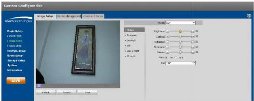
5.1.1.1 Picture
Step 1
Select "Basic Setup > Image Setup > Picture" as shown in Figure 5-1.
text_image
Camera Configuration Image Setup Profile Management Zoom and Focus Profile: Day • Picture • Exposure • Backlight • WB • Easy & Night • Hit Light Background: Cassion: Substation: Sharpness: Grenesis: Noise: ON OFF Flu: 150° Live Default Reset SaveFigure 5-1
| Parameter | Note |
| Saturation | Adjusts the color saturation. The color becomes darker when the value is increased. If the value is set too low, the image will look black and white. This does not affect the overall brightness of the image. |
| Sharpness | Adjusts the sharpness level of the edge on the image. Increasing the sharpness will also increase image noise. |
| Gamma | Changes the Image brightness and Improve the dynamic dplay range of the image. |
| Mirror | Flips the image horizontally. |
| Flip | Changes the display direction of the image.90°: Ro ates the image clockwise 90°270°: Rotates the image counter-clockwise 90°180: Flips the image vertically.Note5Set the mainstream resolution to 1920x1080 to use the flip function. |
Step 3
Click "Save" to save the settings.
5.1.1.2 Exposure
Step 1
Select "Basic Setup > Image Setup > Exposure" as shown in Figure 5-2.

text_image
Camera Configuration Image Setup Photo Management Zone and Focus Image LayStep 2
Set exposure parameters; please refer to the following table for more details?
| Parameter Note | |
| Anti-flicker | Outdoor58+z68+z (used in the %nited States) |
| Mode | Camera exposure modeNote5When "Anti-flicker" is set to "Outdoor", the "exposure mode" can be set as "gain priority" or "shutter priority" mode7The options are:Auto: image brightness is adjusted automatically according to the environment7Gain priority: The device can adjust automatically according to the gain range set during normal exposure range in different scenes7Shutter priority: The device can adjust automatically according to the shutter range set during normal exposure range in different scenes7Manual: Set the gain value and shutter value manually7 |
| Auto Iris | The lens iris can auto adjust the size according to the environment after auto iris is enabled, then the image brightness will change accordingly7The iris value reaches the max when disabling auto iris, the lens iris will not change according to the environment brightness7 |
| 9D NR | Multiple frames are processed and then noise is reduced by using the interframe information between the previous and the latter frame7 |
5.1.1.3 Backlight
Backlight mode options are BLC, WDR and HLC.
- BLC: compensates for high backlight areas behind a subject to make the subject more visible.
- WDR: balances washed out image with a large dynamic range. Typically used for lobbies, where the camera is pointing towards the door.
- HLC: reduces exposure from bright light sources such as headlights. This can be applied in areas such as toll gates, entrance and exit of the parking lots, etc.
Step 1
Select "Basic Setup > Image Setup > Backlight", which will display the interface shown in Figure 5-3.
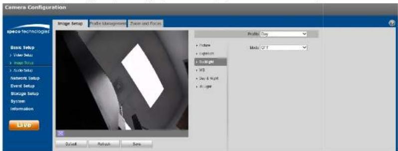
text_image
Camera Configuration Image Setup Profile Management Zone and Focus Profile Day Movie GT Basic Setup Video Setup Image Setup Audio Setup Network Setup Event Setup Storage Setup System Information Live Default Refresh SetsFigure 5-3
Step 2
Set the backlight parameter.
● BLC can be set to default mode or customized mode.
When "Default" mode is selected, the system adjusts automatically to the environment, to make the darkest part of the image to be seen.
5.1.1.4 WBdd
WB (white balance) is used to adjust colors in the image so that objects that appear white in person are shown as white in the camera.
Step 1
Select "Basic Setup > Image Setup > WB", which will display the interface shown in Figure 5-4.
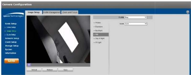
text_image
Camera Configuration Image Setup Profile Management Zoom and Focus Profile Day • Picture • System • Backlight • 300 • Day & Night • Light Model: Auto Basic Setup • Video Setup • Image Save • Audio Setup Network Setup Event Setup Storage Setup System Information Live Default Refresh SaveFigure 5-4
Step 2
Set the mode.
- When set to "Auto", the system will compensate automatically for the white balance depending on the environment.
- When set to "Natural", the system will compensate based on natural light settings.
- When set to "Street Lamp", the system will compensate based on an outdoor scene at night.
- When set to "Outdoor", the system will compensate based on most outdoor scenes with natural light and artificial light.
5.1.1.5 Day & Night
This is to set up color and monochrome switching.
Step 1
Select "Basic Setup > Image Setup > Day & Night", shown in Figure 5-5.
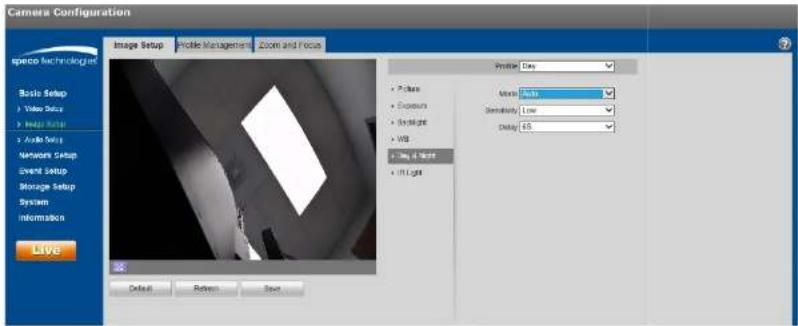
text_image
Camera Configuration Image Setup Profile Management Zoom and Focus Profile: Day • Picture • Exposure • Spotlight • WB • Day & Light • In Light Movie: Auto Sensitivity: Low Delay: 45 Live Default Refine SaveFigure 5-5
Step 2
To set the day & night parameters, refer to the following table for more details.
| Parameter Note | |
| Mode | ● Color: The camera image is always displayed in color.● Auto: The camera switch automatically between color and black & white, depending on the light level.● Black & white: The camera image is always displayed in black & white. |
| Sensitivity | The parameter can be set when the "Day/Night Mode" is set to "Auto".Higher sensitivity means that the mode will switch back and forth from color and black and white more easily. |
5.1.1.6 IR Light
IR LEDs can be controlled in this section.
Step 1
Select "Basic Setup > Image Setup > IR Light", shown in Figure 5-6.

text_image
Camera Configuration Image Setup Profile Management Zoom and Focus Profile Day Picture Exposure Background VDD Day & Night #1 Light Maple SmartR Basic Setup > White Setup > Image Setup > Audio Setup Network Setup Event Setup Storage Setup System Information Save Default Preview SaveFigure 5-6
Step 2
Set the mode.
- When set to "Manual", the brightness of the IR LEDs can be set manually.
- When set to "Smart IR", the system will adjust the LED brightness according to the actual scene.
- When set to "Off", IR LEDs will not operate even in darkness.
Step 3
Click "Save" to save the settings.

text_image
Camera Configuration Image Setup Photo Management Positive: Buy • Pictures • Exposure • Backlight • WS • Day & Night • In Logit • Reset • Fish Eye Install Model: Ceiling Recent Model: TO Live Details Refresh SaveStep 2
Select the desired parameters. Description are listed in the table below
| Parameter | >unction |
| Installation Mode | Three installation modes are available:Ceiling, wall, and ground.The orientation of the image will vary depending on the mode. |
| When a specific record mode is set, the output stream will be the dewarped image on the mode that was set. "his is helpful for situations where a recorder does not have the ability to dewarp the image.After setting the mode, click Save to change to that view. Available record modes will vary according to the different installation modes. |
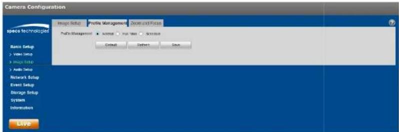
5.1.1.8 Profile Management
Image settings can be set to different values depending on the profile that's being used.
Step 1
Select "Basic Setup > Image Setup > Profile Management" to display the "Profile Management" tab.
Step 2
Set the profile.
- When set to "Normal", the system will monitor according to the normal configuration.
text_image
Camera Configuration Image Setup Profile Management Zoom and Focus Photo Technologies Photo Management ● some ● No. 100 Software Default Refresh Save Basic Setup > View Setup > Image Setup > Audio Setup Network Setup Event Setup Storage Setup System Information LiveFigure 5-8
- When set to "Full Time", the profile can be set to always use the Day configuration or the Night configuration.

text_image
Camera Configuration Image Refuse Profile Management Painted Focus- When set to "Schedule", a specified period of the day can be used for the Day configuration and the rest of the day for the Night configuration. Click and slide the bar to set the time period.
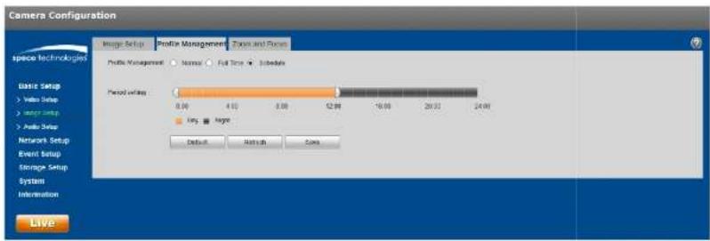
text_image
Camera Configuration Image Setup Profile Management Time and Form space technologies Profile Management Normal Full Time Subdays Basic Setup Video Setup Audio Setup Period setting 8.00 4.00 3.00 12.00 -16.00 20.00 24.00 Imp Ampc Default Refresh Core LiveFigure 5-10
Step 3
Click "Save" save the settings.
Note5
Click "Default" to restore the device to the default settings. Click "Refresh" to check the latest configuration of the device.
5.1.1.9 Zoom and Focus
Note5
This applies to only models with motorized lens.
Step 1
Select "Basic Setup > Image Setup > Zoom and Focus", shown in Figure 5-11.

text_image
Camera Configuration Image Setup Profile Management Zoom and Focus Space Technologies Basic Setup 2. Write Setup 3. Image Setup 4. Auto Setup Network Setup Event Setup Storage Setup System Information Live Zoom Zoom at: Zoom in Speed: 20 Focus: New: Far: Speed: 20 Auto Focus History All Refreshigure 5-11
Step 2
The focal length can be set by pressing "+" or "for Zoom or dragging the slider bar. Adjust the speed as desired.
Step 3
ocus can be adjusted manually, by pressing "+" or dragging the slider block.
Note5
- Click "Auto >ocus" to adjust the focus automatically after a manual adjustment.
- If the image fails to focus after a few times of adjustment, click "Restore All" to reset the lens and remove the accumulative errors of the lens.
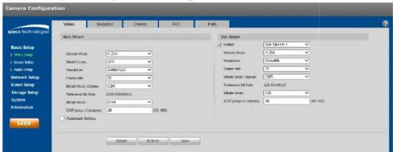
5.1.2 Video Setup
5.1.2.1 Video
Step 1
Select "Basic Setup > Video Setup > Video" shown in Figure 5-12.
text_image
Camera Configuration video Snapshot Overlay ROI Path Main Stream Video Sub Stream Filter Sub Camera 1 Figure Mode -254 Resolution 760x800 Face rate 15 Setup Mode (Range) 250 Preference Mode Rate 200-NC/NC/S Offset Mode 768 GDP (Group of Detrums) 20 (N=150) Video Main Stream Select Mode: H:254 Select Mode: C:7 Resolution: 2588x1/20 Face rate: 20 Feature Mode Change: C:96 Reference Mode Rate: 2000-1000x3/s Noise Mode: GDP (Group of Detrums): 20 (N=150) Postreset Settings Live Default Finish HelpFigure 5-12
Step 2
Refer to the following table for more details on setting the video stream parameters.
| Parameter | Function |
| Sub Stream Enable | Select “Enable” to enable the sub stream.Depending on the model, there may be a second sub stream available. |
| Encode mode | Select the compression to be used. |
| Parameter | >unction |
| Reference Bit Rate | Recommended bit rate range based on the resolution. |
| Bit Rate | Set the bit rate value7 Note that higher bit rate provides a better image quality, but also results in more storage usage. |
| SVC 6scalable video coding) | SVC can dynamically adjust the stream based on the network conditions? Can be turned on or off depending on the client being used? |
| GOP 6group of pictures) | Determines how many P frames are allowed in between two I frames? I frameis the beginning frame of a unique scene? A GOP value of frame rate x 2 or lower is recommended. |
| Watermark Settings | Check to enable watermarking on the video7 |
| Watermark Character | Enter the watermark text to be used for verification. |
Step 9
Click "Save" to save the settings7
5.1.2.2 Snapshot
The snapshot interface is shown as in >figure 5-197
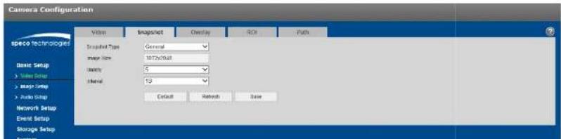
text_image
Camera Configuration Video Snapshot Overlay Size Paths spec technologies Snapshot Type: General Image Size: 100x300x300x300x300x300x300x300x300x300x300x300x300x300x300x300x300x300x300x300x300x300x300x300x300x300x Basic Setup Value Setup Image Setup Audio Setup Network Setup Event Setup Storage Setup System| Sets the image quality, with 6 being the highest quality; | |
| Interval | Interval of how many seconds between snapshots; |
5.1.2.3 Video Overlay
igure 5-14 shows the OSD options7
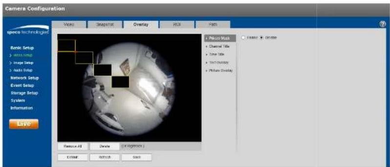
text_image
Camera Configuration specio Technologies Basic Setup + Image Setup + Image Setup + Audio Setup Network Setup Event Setup Storage Setup System Information Live Resource All Device Use In millions Erase Sketch Save + Recru Mask + Channel Title + Time Title + Text Overlay + Picture Overlay + Easter + Dromeigure 5-14
Please refer to the following sheet for detailed information?
| Parameter | >unction |
| Privacy Masking | ● %p to 4 privacy mask zones can be defined? ● Privacy mask blocks out the image in the defined areas. |
Check "Enable" and use the mouse to define the desired region7 Click "Save" to save the settings7 See >igure - 157
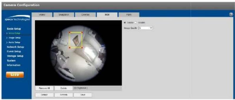
text_image
Camera Configuration video Snapshot Overlay ROI Flash Basic Setup 1 Image Setup 2 Image Setup 3 Auto Setup Network Setup Event Setup Storage Setup System Information LIVS Remove All Delete OK Refreshout Delete Finish Saveigure 5-15
5.1.2.5 Path
Error! Reference source not found.16 shows the interface for setting up storage paths for snapshots and recordings7
There are 4 types of save paths:
• Live view snapshot
- Playback snapshot
- Playback clip download
- Playback video cut download (within playback, a clip with a specific time period can be defined to be downloaded)
Click the Save button to save the setup7
Camera Configuration
igure 5-16
5.1.3 Audio
Applies only to models with audio capability.
The audio interface is shown in >igure 5-17.

text_image
Camera Configuration Audio Setup Create Main Stream ✓ Filter Exclude Mode: 0.71 Mb Sampling Frequency: 0 Not Stream ✓ Order: Full Circle 1 Exclude Mode: 0.71 Mb Sampling Frequency: 0 Include Aboard Type: Level Value Filter: L4500 Macrolensing Volume: 50 System Volume: 50 Default Network Saveigure 5-17
Please refer to the following sheet for detailed information.
| Parameter | Function |
| Enable | Audio can be enabled only when the video stream is enabled.. |
| Encode mode | Select the applicable compression between G.711A, G.711Mu, G.726, and AAC.This applies to both the audio input and 2-way audio. |
5.2 Network Setup
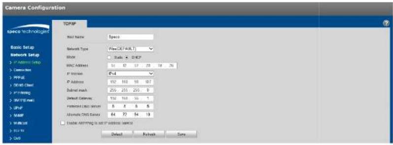
5.2.1 IP Address Setup
or IP address setup, IPv4 and IPv6 are both supported. IPv4 supports static IP and D+CP. IPv6 supports static IP only. If the IP address is modified, the web viewer will automatically jump to the new IP address.
text_image
Camera Configuration TCP/IP Wire Name: Space Network Type: Web DEFAULT Mode: Static + DHCP MAC Address: 52 67 77 28 76 26 IP Version: IP-4 IP Address: 192 188 160 187 Submit mask: 256 251 255 0 Default Connection: 132 138 155 1 Functional Data Status: 8 8 8 8 Alternate CNS Server: 64 72 54 19 □ Enable Anything to set IP address service: Default Refresh Saveigure 5-18
Please refer to the following sheet for detailed information.
| Parameter | >unction |
| +ost Name | Set the device name. Maximum of 15 characters is supported. |
| Network Type | Default is wired. |
| Mode | Select between static and D+CP. If setting to static, make sure that the network does have static IP addresses available for use. When using D+CP, make sure that the network has the capability to assign |
| Preferred DNS | DNS IP address. |
| Alternate DNS | Alternate DNS IP address. |
| Enable ARP/Ping set device IP address service. | This can be used to modify or set the device IP address by utilizing the Mac address.Before the operation, make sure the network camera and the PC are in the same LAN.Refer to the steps listed below.Step 1:Set the network camera and the PC to be on the same LAN.Step 2:Get the Mac address from the label of the network camera.Step 3:Go to the cmd prompt and then enter the following commands.arp -s |
| ping -l 480 -tSuch as: arp -s 192.168.0.125 11-40-8c-18-10-11 ping -l 480 -t 192.168.0.125Step 4:Reboot the device.Step 5:Check if the setup is OK by looking at the output information such as “Reply from 192.168.0.125 ...” from the command output lines.Step 6:Open the browser and then enter the IP address to access the camera. |
5.2.2 Connection
5.2.2.1 Connection
The connection interface is shown in Figure 5-19.
Camera Configuration
igure 5-19
Refer to the following table for more information. Typically, if the device is being installed on an NVR or SecureGuard in the same LAN, these ports can stay at the same values.
| Parameter | >unction |
| Max connection | Defines the number of max web connections that are allowed for the device. The value ranges from 1 to 20. Default connection amount is 10. |
| TCP port | Port range is 1025~65534. The default value is 37777. |
| %DP port | Port range is 1025~65534. The default value is 37778. |
| +TTP port | Port range is 1025~65524. The default value is 80. |
| RTSP port | The default value is 554. |
| +TTPs Port | +TTPs communication port, range is 1025~65534, default is 443. |
Note:
- 0 \~1024, 37780\~37880, 1900, 3800, 5000, 5050, 9999, 37776, 39999, 42323 are all special ports. %ser cannot modify them.
- Avoid using default values of other ports.
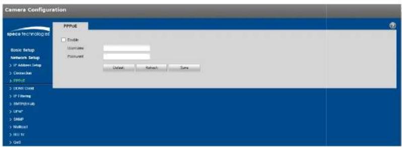
5.2.3 PPPoE
The PPPoE interface is shown in >igure 5-20.
Enter the username and password that were provided by the ISP, and click "Enable". The network camera will automatically establish a network connection if the credentials are correct. The IP address will be automatically modified to the dynamic IP address of the acquired WAN.
Note5
Disable %PnP before enabling PPPoE, which can cause a conflict.
text_image
Camera Configuration Space Technology Basic Setup Network Setup: > IP Address Setup > Connection > PPPUE > I/OOS User > IP Firing > SMTP(Excl) > Other > SMTP > Multisat > HRT IV > Card PPUE Enable UserName: Password: Default Retrench Saveigure 5-28
5.2.4 DDNS Client
The DDNS interface is shown in >igure 5-217
Enable DDNS and click "Save"7 If the connection is successful, the status will indicate that it is connected.

text_image
Camera Configuration DDFS Client □ Enable Senior Address: specidisina.msf Device Class: Link State: Shortenedo Not The DDFS Sector has been added Default Refresh Save Basic Setup Network Setup > IP Address Setup > Customer > FTP > USB Client > IP Setting > BATHS User > UHF > SAMP > Mail out > 802 to > Cus Space Technologies
text_image
Camera Configuration IP Filtering Trusted Size IP address MAC address Mesh Delete Basic Setup Network Setup > IP Address Setup > Connection > PPPG > USB Client > IP Access > SIM (Power) > UMP > NAMF > Network > LUX to > Out Add/MAC Default Network Save Restore Asigure 5-22
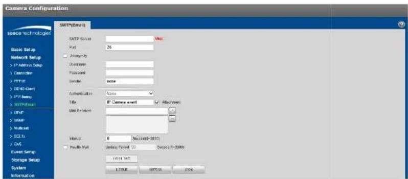
5.2.6 SMTP (Email)
The email interface is shown in >igure 5-297
text_image
Camera Configuration SMTP(Default) SMTP Status: Port: 25 Angrisely Uniprotal Password: Sender: none Authentication: None Title: IP Camera event Attach from: Send Sender: Interact: 0 Send send: 100 Send send: 10000000000000000000000000000000000000000000000000000000000000000000000000000000000000000000000000000 E23488 WNTOR USSRigure 5-29
Refer to the following table for more information:
| Parameter | >unction |
| SMTP Server | Email server, such as smtp7gmail7com, et7 |
| Port | Default value is 257Modify as necessary7 |
| Anonymity >or | email servers which support anonymous email function7 The information of the sender wouldn't be displayed7 |
| %ser Name | The user name of the sender's email account. |
| Password | The password of sender's email account; |
| Interval | The send interval range is from 8 to 9688 seconds7 8 mears there is no interval; |
| Email test | The system will send out an email once to test the connectivity;Before the email test, make sure to save the email setup information7 |
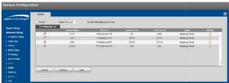
5.2.7 UPnP
%PnP can be used to allow port forwarding on a router without user intervention? Typically, residential routers have %PnP enabled while commercial routers have it disabled by default? See >igure -24 for the interface?
text_image
Camera Configuration UPHP Basic Setup Network Setup > IP Address Setup > Connection > IP Path > I/O/CHI > IP Flashing > HTTP User > I/O/CHI > I/O/CHI > I/O/CHI > I/O/CHI > I/O/CHI > I/O/CHI > I/O/CHI > I/O/CHI > I/O/CHI > I/O/CHI > I/O/CHI > I/O/CHI > I/O/CHI > I/O/CHI > I/O/CHI IP Address Setup TCP TCP TCP TCP TCP TCP TCP TCP TCP TCP TCP TCP TCP TCP TCP TCP TCP TCP TCP TCP TCP TCP TCP TCP TCP TCP TCP TCP TCP TCP TCP TCP TCP TCP TCP TCP TCP TCP TCP TCP TCP TCP TCP TCP TCP TCP TCP TCP TCP TCP TP Address Setup TCP Address Setup TCP Address Setup TCP Address Setup TCP Address Setup TCP Address Setup TCP Address Setup TCP Address Setup TCP Address Setup TCP Address Setup TCP Address Setup TCP Address Setup TCP Address Setup TCP Address Setup TCP Address Setup TCP Address Setup TCP Address Setup TCP Address Setup TCP Address Setup TCP Address Setup TCP Address Setup TCP Address Setup TCP Address Setup TCP Address Setup TCP Address Setup TCP Address Setup TP Address Setup TP Address Setup TP Address Setup TP Address Setup TP Address Setup TP Address Setup TP Address Setup TP Address Setup TP Address Setup TP Address Setup TP Address Setup TP Address Setup TP Address Setup TP Address Setup TP Address Setup TP Address Setup TP Address Setup TP Address Setup TP Address Setup TP Address Setup TP Address Setup TP Address Setup TP Address Setup TP Address Setup TP Address Setup TIP Address Setup TIP Address Setup TIP Address Setup TIP Address Setup TIP Address Setup TIP Address Setup TIP Address Setup TIP Address Setup TIP Address Setup TIP Address Setup TIP Address Setup TIP Address Setup TIP Address Setup TIP Address Setup TIP Address Setup TIP Address Setup TIP Address Setup TIP Address Setup TIP Address Setup TIP Address Setup TTP Address Setup TTP Address Setup TTP Address Setup TTP Address Setup TTP Address Setup TTP Address Setup TTP Address Setup TTP Address Setup TTP Address Setup TTP Address Setup TTP Address Setup TTP Address Setup TTP Address Setup TTP Address Setup TTP Address Setup TTP Address Setup TTP Address Setup TTP Address Setup TTP Address Setup TTP Address Setup TIP Address Setup TIP Address Setup TIP Address Setup TIP Address Setup TIP Address Setup TIP Address Setup TIP Address Setupigure 5-24
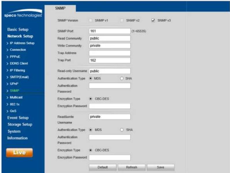
5.2.8 SNMP
The SNMP interface is shown in >igure 5-257
Before using SNMP, make sure to install an SNMP management tool and set the parameters: After setup, the device must be restored to activate the new setup?
text_image
speco technologies SNMP SNMP Version SNMP v1 SNMP v2 SNMP v3 Basic Setup Network Setup > IP Address Setup > Connection > PPPoE > DONS Client > IP Filtering > SMTP(Email) > UPnP > SNMP > Multicast > 802.1x > QoS Event Setup Storage Setup System Information Live SNMP Port 161 (1-65535) Read Community public Write Community private Trap Address Trap Port 162 Read-only Username public Authentication Type MD5 SHA Authentication Password Encryption Type CBC-DES Encryption Password Read&write private Username Authentication Type MD5 SHA Authentication Password Encryption Type CBC-DES Encryption Password Default Refresh Save| Parameter Function | |
| Read community | Read-only access to all SNMP targets, default is public. Note: Only number, letter, _, and – are supported. |
| Write community | Read/write access to all SNMP targets, default is private. Note: Only number, letter, _, and – are supported. |
| Trap address | The destination address of the Trap information from the proxy program of the device. |
| Trap Address | Address for where to send Trap message. |
| Trap Port | Port which sends Trap message, default is 162, range 1~65595. |
The parameters below are available when SNMP v9 is enabled.
| Parameter Function | |
| SNMP Version SNMP v9 | |
| Read-only %sername | Default is public. Note: Name can consist of numbers, letters and underline. |
| Read/Write %sername | Default is private. Note: Name only can be number, letter and underline. |
| Authentication | Select MD5 or S+A, default is MD5. |
| Authentication Password | Password must be not less than 8 characters. |
| Encryption | CBC-DES |
| Encryption Password | Password must be not less than 8 characters. |
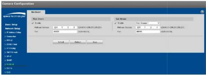
5.2.9 Multicast
The multicast interface is shown in >igure 5-26.
Multicast is a transmission mode of data packets. When there are multiple destinations that will receive the same video stream, multicast can be used to reduce bandwidth and CP% load on the device. To set up multicast, make sure that network switches/routers that are being used have multicast support.
text_image
Camera Configuration MultiStream Speco Technologies Basic Setup Network Setup IP Address Setup Connection PPFIE CONE Cloud PTFSING RPTFS NET UPUT SMP PUBI GOS MultiStream Base Stream Enable MultiStream: 224 1 0 0 (224.8.9 - 239.255 265.25) Port: 40000 (1025-40014) Sub Stream Enable Sub Stream 1 MultiStream: 224 1 2 4 (224.8.9 - 239.255 265.25) Port: 40010 (1025-40014) Default Reset Saveigure 5-26
Refer to the following table for more information.
| Parameter >unction | |
| Enable | Select to enable multicast function. Main stream and sub stream cannot be used at the same time. |
| Multicast address | Main/sub stream multicast default address is 224.1.2.4 and its range is 224.0.0.0~239.255.255.255. |
| Port | Multicast port. Main stream is 40000. sub stream1 is 40016. sub stream2 is 40032 |
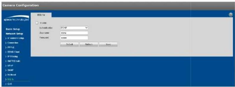
5.2.10 802.1x
802.1x (port based network access control protocol) provides an authentication method for a device to connect to a LAN.
text_image
Camera Configurations 802.1x Speed Technologies Basic Setup Network Setup > W Address Setup > Connection > PPUE > GUSB Clock > PPTSling > MPTHEnroll > LIFP > RAMP > Nucleus > EUI Is > Ctrl Automatic: FPAP Distance: 100% Password: ****. Default Reset Canceligure 5-27
Refer to the following table for more information.
| Parameter | >unction |
| Authentication | PEAP (protected EAP protocol). |
| %sername | Enter the user name, which is authenticated by the server. |
| Password | Enter the password. |
5.2.11 QoS
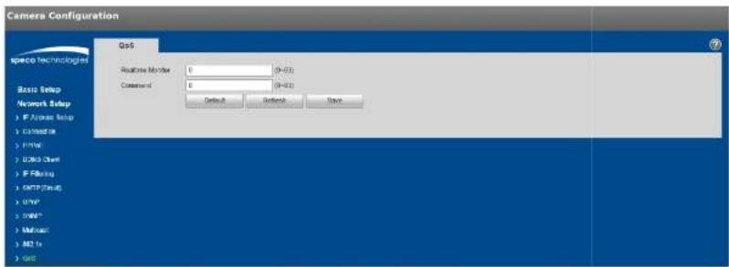
text_image
Camera Configuration QoS Network Setup IF Access Setup Connection Driver USB Client IF Filtering SMTP Cloud UWIP SNAP Mailout M2 To Auto Realtime Number: 0 (N=33) Current of: 0 (N=33) Default Default SaveFigure 5-28
5.2.12 HTTPS
For devices that have HTTPS capability, a certificate can be created or a signed certificate can be uploaded.
Step 1
Create a certificate or upload a signed certificate.
● To create a certificate, follow the directions below.
- Select "Network Setup > HTTPS", shown in Figure 5-29.
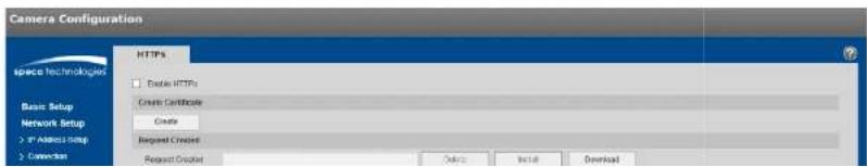
text_image
Camera Configuration SPACE TECHNOLOGIES Basic Setup Network Setup > In Address Setup > Connection HTTPS Enable HTTPS Create Certificate Create Request Created Request Cropped Options Install Download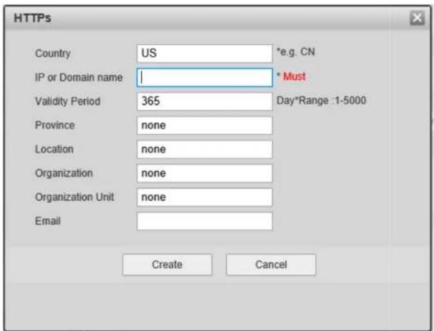
text_image
HTTPS Country US *e.g. CN IP or Domain name | * Must Validity Period 365 Day*Range :1-5000 Province None Location None Organization None Organization Unit None Email Create Canceligure 5-98
97 >ill in all fields and click "Create"7A message will pop up stating that the certificate has been created successfully7 Make sure that the IP address or the domain name is the same as that of the device;
47 Click "Install" and the certificate will be installed on the device7
57 Click "Download" and save the file on the PC7

text_image
Save As Libraries Search Libraries Organize Desktop Downloads Recent Places Libraries Documents Music Pictures Videos Computer Local Disk (C:) DISK1_VOL2 (D:) DISK1_VOL3 (E:) Libraries Open a library to see your files and arrange them by folder,... Documents Library Music Library Pictures Library Videos Library File name: RootCert.cer Save as type: (*.cer) Hide Folders Save Canceligure 5-91
67 Double click on the downloaded file7 The system will display the shown in >figure 5-927

text_image
Certificate General Details Certification Path Certificate Information This CA Root certificate is not trusted. To enable trust, install this certificate in the Trusted Root Certification Authorities store. Issued to: test Issued by: test Valid from 2016/ 7/ 8 to 2020/ 7/ 7 Install Certificate... Issuer Statement Learn more about certificates OKigure 5-92
- Click "Install Certificate" and the Certificate Import Wizard will show, shown in >igure 5-99.
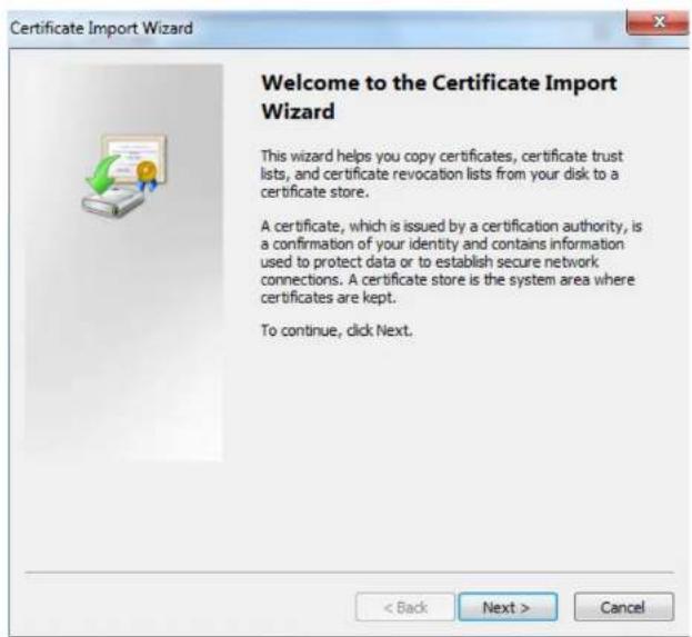
text_image
Certificate Import Wizard Welcome to the Certificate Import Wizard This wizard helps you copy certificates, certificate trust lists, and certificate revocation lists from your disk to a certificate store. A certificate, which is issued by a certification authority, is a confirmation of your identity and contains information used to protect data or to establish secure network connections. A certificate store is the system area where certificates are kept. To continue, click Next.igure 5-99
- Click "Next" and select "Place all certificates in the following store". Click on Browse and select "Trusted Root Certification Authorities".

text_image
Certificate Import Wizard Certificate Store Certificate stores are system areas where certificates are kept. Windows can automatically select a certificate store, or you can specify a location for the certificate. ○ Automatically select the certificate store based on the type of certificate ● Place all certificates in the following store Certificate store: Trusted Root Certification Authorities Browse... Learn more about certificate stores < Back Next > Canceligure 5-34
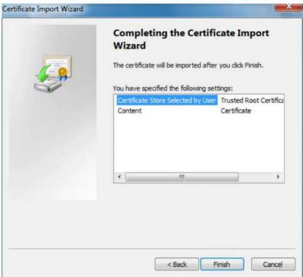
- Click "Next" and "Completing the Certificate Import Wizard" will show, which is shown in >figure 5-35.
text_image
Certificate Import Wizard Completing the Certificate Import Wizard The certificate will be imported after you click Finish. You have specified the following settings: Certificate Store Selected by User Trusted Root Certifica Content Certificate < Back Finish Canceligure 5-95
187 Click ">inish", and "Security Warning" dialog box will show, which is shown in >figure 5-967
Security Warning

You are about to install a certificate from a certification authority (CA) claiming to represent:
test
Windows cannot validate that the certificate is actually from "test". You should confirm its origin by contacting "test". The following number will assist you in this process:
Thumbprint (sha1): 6D811FD2 E82313A8 663514ED 2CA36E6B 7D425FA6
Warning:
If you install this root certificate, Windows will automatically trust any certificate issued by this CA. Installing a certificate with an unconfirmed thumbprint is a security risk. If you click "Yes" you acknowledge this risk.
Do you want to install this certificate?
Yes
No
igure 5-96
- Click "Yes" and a dialog box will pop up showing that the import was successful. Click "Ok" to complete downloading the certificate.
text_image
Certificate Import Wizard The import was successful.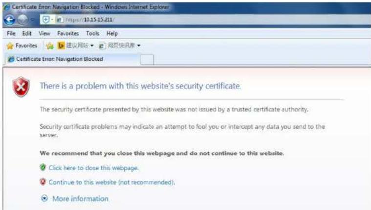
text_image
Certificate Error: Navigation Blocked - Windows Internet Explorer File Edit View Favorites Tools Help Favorites 建议网站 网页快讯库 Certificate Error: Navigation Blocked There is a problem with this website's security certificate. The security certificate presented by this website was not issued by a trusted certificate authority. Security certificate problems may indicate an attempt to fool you or intercept any data you send to the server. We recommend that you close this webpage and do not continue to this website. ✓ Click here to close this webpage. ✓ Continue to this website (not recommended). ● More informationigure 5-98
5.3 Event Setup
5.3.1 Video detection
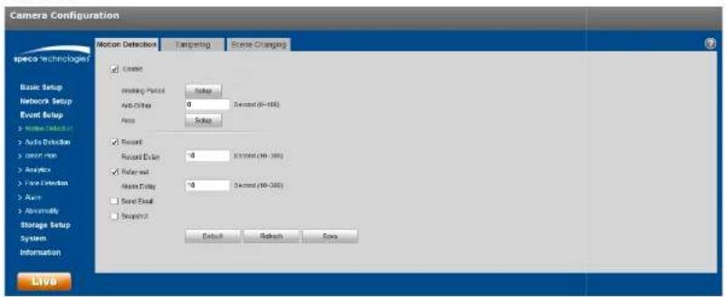
Select "Event Setup > Video Detection > Motion Detection" to display the motion detection interface shown in
Figure 5-39.
text_image
Camera Configuration Motion Detection Tampering Reset Changing ■ Enable ■ Reset Panel Setup ■ Anti-Other 0 Decord (40-100) ■ Focus Setup ■ Recent Recent Dyeer 0 31/2006 (40-380) ■ Delayed Active Dyeer 0 Decord (40-380) ■ Sound Event ■ Snapshot Default Refresh OK LiveFigure 5-39
Step 2
Select "Enable" to enable motion detection.
Step 3
Set up motion detection zone.
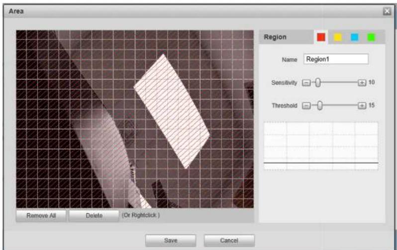
text_image
Area Region Name Region1 Sensitivity 10 Threshold 15 Remove All Delete (Or Rightclick ) Save Canceligure 5-48
27 %p to 4 different zones can be set, with a different set of defined areas, sensitivities, and threshold values? The name field is the nickname for the corresponding zone?
97 +higher sensitivity value means that it is easier to trigger a motion event? The threshold \value represents how much of the overall motion detection zone needs to have motion in order for the motion event to trigger? The entire video image is the defined as the motion zone by default?
47 Click "Save" to save the settings7
| Parameter Function | |
| Anti-dither | The device only generates one alarm during the anti-dither period. The value ranges from 0s to 100s. |
| Area | Motion zone setup, as described in this section. |
| Record | If enabled, when a motion alarm occurs, the device will record to the destination that's set under the Storage Setup > Destination section. |
| Record Delay | System can delay the record for specified time after alarm ended. The value ranges from 10s to 300s. |
| Relay out Enable | it for a relay out to an alarm device. This applies to only models with a relay output connection. |
| Alarm Delay | System can delay the alarm output for a specified time after the alarm ends. |
| Send Email | If enabled, the device can send out an email when a motion alarm occurs.An email address must first be set up In Network Setup. |
| Snapshot | Enable to generate a snapshot when a motion alarm occurs. The snapshot schedul can be set up in Storage>Schedule. |
Step 5
Click "Save" to save the settings.
5.3.1.2 Tampering
Step 1
Go to the Tampering tab to display the interface of "Video Tampering" which is shown in Figure 5-41.
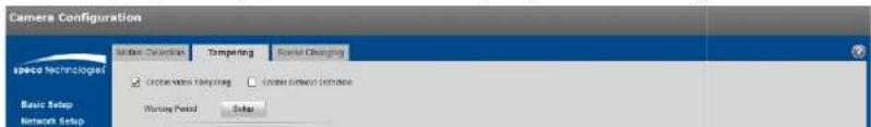
text_image
Camera Configuration Speco Technologies Basic Setup Network Setup Custom Settings Ranking Serial Settings Selection Working Period SubSet up the parameters. The parameters for alarm actions are the same as motion detection.
Step 3
Click "Save" to save the settings.
5.3.1.3 Scene Changing
Step 1
Go to the Scene Changing tab to display the interface of "Scene Changing". Scene Changing will generate an alarm when the scene in the video image changes drastically.
Step 2
Check "Enable" to enable the function of scene changing.
Step 3
Set up the parameters. The parameters for alarm actions are the same as motion detection.
Step 4
Click "Save" to complete the setup of scene changing.
5.3.2 Audio Detection
Step 1
Select "Event Setup > Audio Detection" to display the interface of "Audio Detection" which is shown in Figure 5-42.

text_image
Camera Configuration speco technologies Basic Setup Network Setup Event Setup > Motion Detection > Audio Detection > Smart Plan > Analytics > Face Detection > Alarm > Abnormality Storage Setup System Information Live Audio Detection Enable Input Abnormal Enable Intensity Change Sensitivity 50 Threshold 50 Working Period Setup Anti-Dither 5 Second (0~100) Record Record Delay 10 Second (10~300) Relay-out Alarm Delay 10 Second (10~300) Send Email Snapshot Default Refresh Saveigure 5-42
| Parameter Function | |
| Anti-dither | The device only generates one alarm during the anti-dither period. The value ranges from 0s to 100s. |
| Record | If enabled, when an alarm occurs, the device will record to the destination that's set under the Storage Setup > Destination section. |
| Record Delay System | can delay the record for specified time after alarm ended. The value ranges from 10s to 300s. |
| Relay out Enable it | for a relay out to an alarm device. This applies to only models with a relay output connection. |
| Alarm Delay | System can delay the alarm output for a specified time after the alarm ends. |
| Send Email | If enabled, the device can send out an email when an alarm occurs.An email address must first be set up in Network Setup. |
| Snapshot | Enable to generate a snapshot when an alarm occurs. The snapshot schedule can be set up in Storage>Schedule. |
5.3.3 Smart Plan
Specific models may have different types of intelligent video functions. Only one type of analytic function can be utilized at a time, which can be enabled in Smart plan.
Step 1
Select "Event Setup > Smart Plan", as shown in Figure 5-43.

text_image
Camera Configuration Space Technologist Smart Plan Basic Setup Network Setup Event Setup > Motion Detection > Audio Intrusion > Smart Plan > Analytics > Auto Ecosystem > Assets > Autonomouss Storage Setup System Information LIVOFigure 5-43
Step 2
Click "Save" to save the settings.
5.3.4 Intelligent Video
Basic requirements of scene selection to take into consideration:
● The total size of the target should not be larger than 10% of the image.
● The target size in the image should be larger than 15x15.
There needs to be some time from when the target appears to when the target is confirmed, so there should be some space on both sides of the line.
Step 1
Select "Event Setup > Analytics".
Step 2
Click "to set the
rule name and select the rule type as "Tripwire" as shown in Figure 5-44.
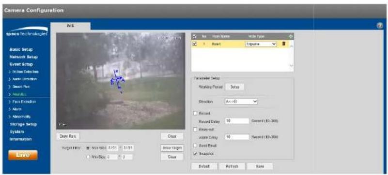
text_image
Camera Configuration IVS Name: Right Name: Right Type 1 Right 1 Perspective Basic Setup Network Setup Event Setup > Unique Document > Auto Environment > Smart Plan > Focus Connection > Altim > Abnormally Storage Setup System Information Live Parameter Setup Working Period: Setup Direction: Ax->B Rearout Rearout Delay: 50 Seconds (10-300) Rearout-out: Altim Delay: 10 Seconds (10-300) Rear Out Swapout Target Range: Max/Min: 50% 60% 80% 100% Min/Stop: 0 0 Close Clear Default Refresh SaveFigure 5-44
Step 3
Click "Draw Rule" to draw a line in the scene. Click the right mouse button to complete the setting.
Step 4
| Parameter Function | |
| Record Delay | System can delay the record for specified time after alarm ended. The value ranges from 10s to 300s. |
| Relay out | Enable it for a relay out to an alarm device. This applies to only models with a relay output connection. |
| Alarm Delay | System can delay the alarm output for a specified time after the alarm ends. |
| Send Email | If enabled, the device can send out an email when an alarm occurs.An email address must first be set up in Network Setup. |
| Snapshot | Enable to generate a snapshot when an alarm occurs. The snapshot schedule can be set up in Storage>Schedule. |
Step 5
Click "Save" to save the settings.
5.3.4.2 Intrusion
Intrusion includes these actions: cross and appears.
- Cross means that an alarm will be triggered when the target enters or exits the area.
● Appears means that an alarm will be triggered when the target appears in the area.
Step 1
In the IVS tab, click “+” to set rule name and select the rule type as “Intrusion” as shown in Figure 5-45.
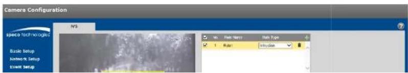
text_image
Camera Configuration speco tech-logic IVS Basic Setup Network Setup Event Setup vs. Rate Start: Rate Type 1 Rule: 3x250mmClick "Draw Rule" to draw an area in the image.
Step 3
Click "Draw Target" to set the size of the target in the image.
Step 4
Refer to the following table for more details on the parameters.
| Parameter Function | |
| Working Period | Set up the schedule for when alarms will get generated by the device. |
| Action | Select Appears or Cross. |
| Record | If enabled, when an alarm occurs, the device will record to the destination that's set under the Storage Setup > Destination section. |
| Record Delay System | Can delay the record for specified time after alarm ended. The value ranges from 10s to 300s. |
| Relay out Enable it | For a relay out to an alarm device. This applies to only models with a relay output connection. |
| Alarm Delay | System can delay the alarm output for a specified time after the alarm ends. |
| Send Email | If enabled, the device can send out an email when an alarm occurs.An email address must first be set up in Network Setup. |
| Snapshot | Enable to generate a snapshot when an alarm occurs. The snapshot schedule can be set up in Storage>Schedule. |
Step 5
Click "Save" to save the settings.
5.3.4.3 Abandoned Object
Abandoned object means that an alarm will be triggered if an object has been left in the scene for longer than
text_image
Camera Configuration IWS Speed Technology Basic Setup Network Setup Event Setup > Motion Direction > Active Defense > Smart Plan > Audio > Free Defense > Audio > Normal > Storage Setup System Information Live Video Setup Target Filter Max Scale: 5100 x 8194 Max Scale: 0 x 0 Draw Target Clear Draw Target Clear Parameter Split: wearing Tilted: 1/100 Keep Time: 10 seconds (0-240) Placord Record Delay: 10 Second (10-200) Binary set Alternate Delay: 10 Second (10-300) Seed Email Snapshot Default Refresh SaveFigure 5-46
Step 2
Click "Draw Rule" to draw an area in the image.
Step 3
Click "Draw Target" to set the size of the target in the image.
Step 4
Refer to the following table for more details on the parameters.
| Parameter Function | |
| Working Period | Set up the schedule for when alarms will get generated by the device. |
| Keep time | Time limit before alarm is triggered. |
Step 5
Click "Save" to save the settings.
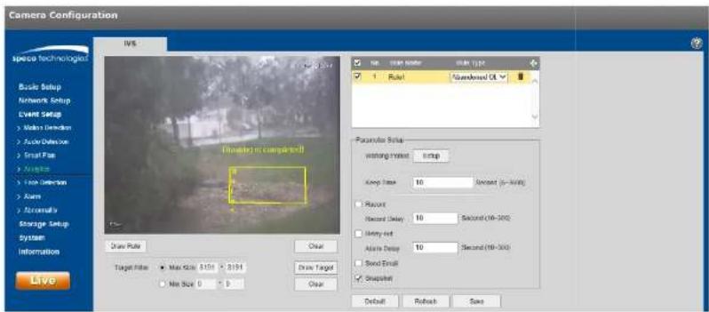
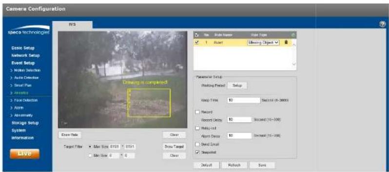
5.3.4.4 Missing Object
Missing object means that an alarm will be triggered if an object has been removed from the scene for longer than the time limit that has been set.
Step 1
In the IVS tab, click " " to set the rule name and select the rule type as "Missing Object", as shown in >figure 5-
47.
text_image
Camera Configuration N/S Erase Technologies Ease Setup Network Setup Event Setup > Main Detection > Auto Detector > Smart Plus > ActiveBox > Plane Detection > Alarm > Abnormally Storage Setup System Information Live Driving is completed Drive Title Clear Target Filter Max Size: 0.01 Min Size: 0 Drive Target Clear Run Name Run Type 1 Run Missing Object Parameters Setup Working Period Setup Stop Time 10 Second (6-3000) Record Record Delay 10 Second (16-100) Multi-cut Alarm Delay 10 Second (16-100) Send Email atched Default Refresh Saveigure 5-47
Step 2
| Parameter Function | |
| Keep time | Time limit before alarm is triggered. |
| Record | If enabled, when an alarm occurs, the device will record to the destination that's set under the Storage Setup > Destination section. |
| Record Delay | System can delay the record for specified time after alarm ended. The value ranges from 10s to 300s. |
| Relay out | Enable it for a relay out to an alarm device. This applies to only models with a relay output connection. |
| Alarm Delay | System can delay the alarm output for a specified time after the alarm ends. |
| Send Email | If enabled, the device can send out an email when an alarm occurs.An email address must first be set up in Network Setup. |
| Snapshot | Enable to generate a snapshot when an alarm occurs. The snapshot schedule can be set up in Storage>Schedule. |
Step 5
Click "Save" to save the settings.
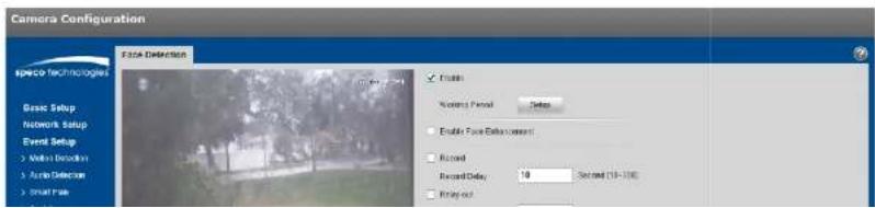
5.3.5 Face Detection
Step 1
Select "Event Setup > Face Detection" to display the "Face Detection" Interface, shown in Figure 5-48.
text_image
Camera Configuration Face Detection Basic Setup Network Setup Event Setup > None Connection > Auto Detection > Smart Face Enable Positive Pencil Setup Enable Face Adjustment Record Record Delay: 10 Second (13-20) Binary outStep 3
Click "Draw Target" to set the size of the target in the image.
Step 4
Refer to the following table for more details on the parameters.
| Parameter Function | |
| Working Period | Set up the schedule for when alarms will get generated by the device. |
| Enable Face Enhancement | Select “Enable Face Enhancement” to enhance the face image when the stream quality is very low. |
| Record | If enabled, when an alarm occurs, the device will record to the destination that’s set under the Storage Setup > Destination section. |
| Record Delay System | can delay the record for specified time after alarm ended. The value ranges from 10s to 300s. |
| Relay out Enable it | for a relay out to an alarm device. This applies to only models with a relay output connection. |
| Alarm Delay | System can delay the alarm output for a specified time after the alarm ends. |
| Send Email | If enabled, the device can send out an email when an alarm occurs.An email address must first be set up in Network Setup. |
| Snapshot | Enable to generate a snapshot when an alarm occurs. The snapshot schedule can be set up in Storage>Schedule. |
Step 5
Click "Save" to save the settings.
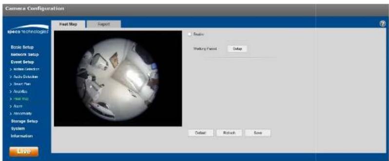
5.3.6 Heat Map
5.3.6.1 Heat Map
Heat map is the set of heat statistics of a moving object, for which a report can be generated. The color range is from blue to red, where blue means the minimum heat value and red means the maximum heat value.
text_image
Camera Configuration Hot Map Export Basic Setup Network Setup Event Setup > White Candles > Auto Dexterity > Smart Plan > Audio > Heat Map > Alert > Annually Storage Setup System Information Live Balance Working Period: Setup Outset Refresh Saveigure 5-49
Step 2
Select "Enable" to enable the heat map function.
Step 3
Set the schedule, in the same way as motion schedule setup.
Step 4
Click "Save" to save the settings.
5.3.6.2 Report
Step 1
Select the Report tab, as shown in >igure 5-50.
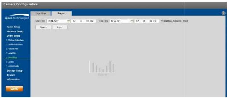
text_image
Camera Configuration Test Map Report Status Time 10-09-2017 12 01 03 40 End Time 10-09-2017 02 10 00 PM Export Date Range is / Next Search Export Randle Setup Network Setup Event Setup Mitar Delusion Auto Connection Invert max Analysis Real Map Aram Assembly Storage Setup System Information Liveigure 5-58
Step 2
Set the begin time and the end time for the report7
Step 9
Click "Search" to generate the statistics and then click "Export" to export the report7
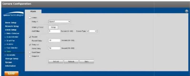
5.3.7 Alarm
text_image
Camera Configuration Alarm Base Setup Network Setup Event Setup Make a Detector Audio Environment Small Plan Analysis Focus Detection Name Annuromity Storage Setup System Information Alarm Record Record Delay Record out Audio Timing Sound Filter Standard Second (5 - 100) Second (10 - 200) Second (10 - 200) Default Refresh OKigure 5-51
| Parameter >unction | |
| Enable Check | to enable relay output7 |
| Relay-in The default is | alarm 17 Some models may have alarm 27 |
| Sensor Type Select between | normally open 6NO) and normally closed 6NC)7 |
5.3.8 Abnormality
Abnormality includes: No SD Card, Capacity Warning, SD Card Error, Disconnection, IP Conflict and %authorized Access7

text_image
Camera Configuration SD Card Networks Signal Access Event Type Slope by Warning Create Capacity Limit 10 % (0-40) Delay out Alarm Delay 10 Record (19-300) Send Data Default Return Save Basic Setup Network Setup Event Setup Make Detection Auto Detector Signal Path Avaplicator Face Detector Alarm Abnormally Storage Setup System Information Liveigure 5-52
Please refer to the following sheet for detailed information?
| Parameter | Function |
| Enable | Check to enable alarm when SD card is abnormal7 |
| Relay out | Enable it for a relay out to an alarm device? This applies to only mocels with a relay output connection7 |
| Alarm Delay | System can delay the alarm output for a specified time after the alarm ends7 |
| Send email | If enabled, the device can send out an email when an alarm occurs? An email address must first be set up in Network Setup7 |
| SD Card Capacity | An alarm can be generated when the free space of the SD card is less than the capacity set here7 |
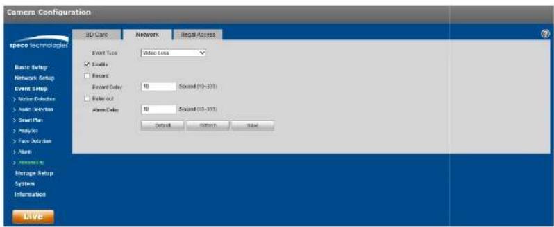
text_image
Camera Configuration SD Card Network Illegal Access Event Touch Video Loss Enable Record Event Delay 10 Sound (10-310) Roller Out 10 Sound (10-310) Place Order Default Service OK Basic Setup Network Setup Event Setup Motion Exchange Auto Inverter Smart Plan Analyse Face Offset Alarm Information Storage Setup System Information Liveigure 5-59
or illegal access, when the credentials are entered illegally, an alarm will be generated each time, up to the number of the times that has been set7 When the limit is exceeded, the user account will be locked for 98 minutes7
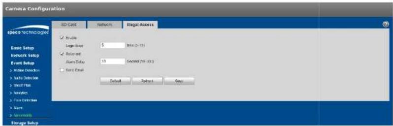
text_image
Camera Configuration SD Card Networks Illegal Access Basic Setup Logic Event 5 Metal (0 - 10) Binary Event Alarm Delay 10 MAXIM (10 - 200) Send Email Default Subtract Save Basic Setup Network Setup Event Setup > Hidden Detection > Auto Detection > Security Plan > Services > Free Drive Set > Alert > Antenna Storage Setup5.4 Storage Management
5.4.1 Schedule
Note:
The record mode found in the Record Control section must be set to Auto or Manual for the device to record according to the set schedule.
5.4.1.1 Record Schedule
Step 1. Click on the Record Schedule tab under "Storage Setup > Schedule", as shown in Figure 5-55.

text_image
Camera Configuration Record Schedule Snapshot Schedule Holiday Schedule General Master Alarm Basic Setup Network Setup Event Setup Storage Setup > Subscription > Destination > Record Central System Information Live Setup Setup Setup Setup Setup Setup Setup Setup Setup Setup Setup Setup Setup Setup Setup Setup Setup Setup Setup Setup Setup Setup Setup Setup Setup Setup Setup Setup Setup Setup Setup Setup Setup Setup Setup Setup Setup Setup Setup Setup Setup Setup Setup Setup Setup Setup Setup Setup Setup Setup Setup Setup Setup Setup Setup Setup Setup Setup Setup Setup Setup Setup Setup Setup Setup Setup Setup Setup Setup Setup Setup Setup Setup Setup Setup Setup Setup Setup Setup Setup Setup Setup Setup Setup Setup Setup Setup Setup Setup Setup Setup Setup Setup Setup Setup Setup Setup Setup Setup Setup Setup Burrton Mercury Tranmey Washdown Thompson Ferry Saturn Hailuri Refresh Refresh SignFigure 5-55
Step 2. Click on Setup on the right for the day for the schedule to be set, as shown in Figure 5-56.
- Set the time periods as necessary. Up to six periods can be set for each day. The periods can be copied to each necessary day of the week.
● Three types of recording can be scheduled: General (continuous), Motion, and Alarm.

text_image
Setup All ✓ Sunday □ Monday □ Tuesday □ Wednesday □ Thursday □ Friday □ Saturday □ Holiday Period1 00 : 00 : 00 - 23 : 59 : 59 □ General ✓ Motion ✓ Alarm Period2 00 : 00 : 00 - 23 : 59 : 59 □ General □ Motion □ Alarm Period3 00 : 00 : 00 - 23 : 59 : 59 □ General □ Motion □ Alarm Period4 00 : 00 : 00 - 23 : 59 : 59 □ General □ Motion □ Alarm Period5 00 : 00 : 00 - 23 : 59 : 59 □ General □ Motion □ Alarm Period6 00 : 00 : 00 - 23 : 59 : 59 □ General □ Motion □ Alarm Save Canceligure 5-56
Step 3. Click Save to return to the record schedule interface.
● Green color stands for continuous record/snapshot.
● Yellow color stands for motion detection record/snapshot.
● Red color stands for alarm record/snapshot.
Step 4. Click Save to save the settings.
5.4.1.2 Snapshot Schedule
The Snapshot schedule is set up in the same manner as Record Schedule. The Interface is shown in >igure 5-57.

text_image
Camera Configuration Record Schedule Snapshot Schedule Holiday Schedule General Medium Alarm space Technologies Basic Setup 0 2 4 6 0 19 12 14 16 18 20 22 245.4.1.3 +oliday Schedule
Specific days such as holidays can be set up to have a different schedule.
Step 1. Click on the +oliday Schedule tab, as shown in >igure 5-58.
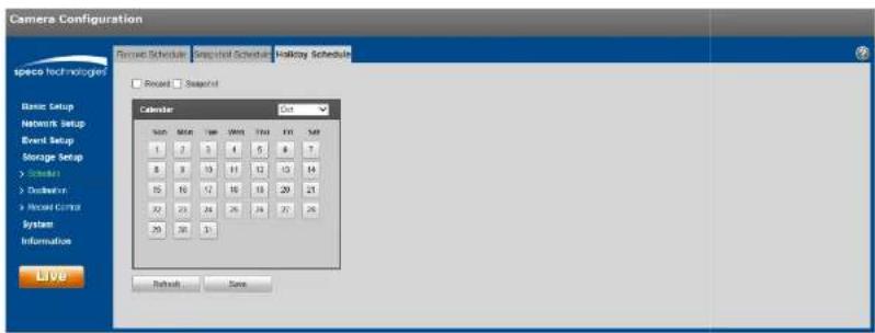
text_image
Camera Configuration Spread Schedule Spread Schedule Holiday Schedule Spread Spread Calendar Date 1 2 3 4 5 6 7 8 9 10 11 12 13 14 15 16 17 18 19 20 21 22 23 24 25 26 27 28 29 30 31 Refresh Saveigure 5-58
Step 2. Select a date to set as a holiday. The selected date will be highlighted in yellow.
Step 3. Check Record and/or Snapshot for the desired recording mode and then click on Save.
Step 4. In the Record Schedule interface or the Snapshot Schedule interface, click on setup next to +oliday and set up the time periods accordingly.
Step 5. Click Save to save the settings.
5.4.2 Destination
5.4.2.1 Path
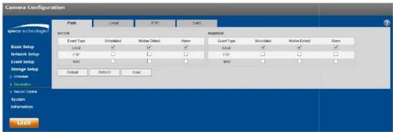
text_image
Camera Configuration Path Local FTP NAS speco technology Record Event Type Scheduled Motion Offset Alarm Snapshot Event Type Scheduled Motion Offset Alarm Local Local Local Network Setup FTP FTP Event Setup MOS MOS Storage Setup > Console > Operation > Record Control System Information Default Refresh Save Liveigure 5-59
5.4.2.2 Local
The local interface is shown in >igure 5-60.
In this interface, information about the Micro SD card is displayed. The card can be also formatted through this interface.

text_image
Camera Configuration Paths Local FTP NAS Direct Name Status Attribute User Cap/Total Cap/Capacity Basic Setup Network Setup Event Setup Storage Setup > Sub-Link > Transaction > Internal Control System Information Read Only Road & Write-Rust Drive Rush Format
text_image
Camera Configuration Push Local FTP NAS Specific Technologies Event Server Address: 8.30.8 Port: 21 (0-6950s) User Name: emergency Password: Remote Directory: Share Emergency Data Default Relaph Save Basic Setup Network Setup Event Setup Storage Setup > reverse > Connection > Record Center System Information Liveigure 5-61
5.4.2.4 NAS
Check the box to enable the NAS function: Enter the applicable connection information? See >igure 5-627

text_image
Camera Configuration Path Local FTP NAS Space Technologies Basic Setup Network Setup Event Setup Storage Setup > Console > Desktop > Record Control System Information Live File(s) Server Address: 0.00.0 Remote Directory: Default Refresh Save5.4.3 Record control
The record control interface is shown in >igure 5-69.
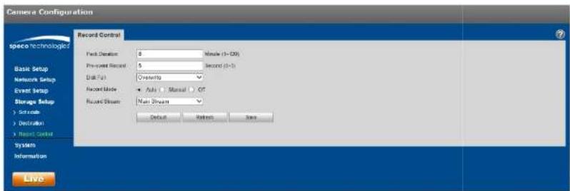
text_image
Camera Configuration Record Control Track Duration 8 Pre-spect Record 5 Disk Fat Cramatics Record Mode ● Auto □ Manual ○ Off Record Stream Main Stream Default Retired Save Liveigure 5-69
Refer to the following table for more information.
| Parameter >unction | |
| Pack Duration | Refers to the duration of each file that gets saved. Default is 8 minutes. |
| Pre-record | Refers to the duration of the recording before the actual event that gets saved. |
| Disk >ull | ● Stop: Stops recording if storage is full● Overwrite: Starts to overwrite the oldest recordings if storage is full |
| Record mode | Auto / Manual / Off. “Off” must not be chosen for the schedule to take effect. |
| Record | Choose between main stream and sub stream. |
5.5 System
5.5.1 General
The General interface is shown in >igure 5-647
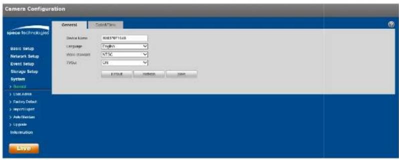
text_image
Camera Configuration General Control Panel Device Name: 80837071548 Language: Tagkos Main standard: NTSC Value: ON EXIT OK Cancel Save Live Inside Factory Default Copyright Auto/Bestion Upgrade Information Liveigure 5-64
| Parameter >unction | |
| Device Name | Nickname for the device can be set here7 By default, the serial number of the device is shown. |
| Video Standard | Displays the video standard, which is NTSC for North America7 |
| TV Out | Some models will have a TV output option7 This can be turned or/off |
The Date & Time interface is shown as in >igure 5-657

text_image
Camera Configuration General Dates Time Date Format: Month-Day Year Time Period: 12-Point-based System Time Zone: GMT+05.00 Current Time: 10-13-2017 03:56:56 PM Short PC UST Enable UST Type Date View Start Time Mar End Sunday 02 00:00 AM End Time New 1st Sunday 02 00:00 AM Syndicate with NTP NTP Below pixel size mg Pyt 123 Module Pres: 30 Module (8x8) Default Reset Save Liveigure 5-65
Please refer to the following sheet for detailed information?
| Parameter >unction | |
| Date format | Select the display format of the date from the dropdown list. |
| Time >format | Select between a 24-hour display and a 12-hour display; |
| Time zone | Set the time zone of the device7 |
| Current Time | Current time of the device7 This can be set manually |
| Sync PC Click | this button to save the device time as the PC time7 |
| DST Enable If | the location utilizes Daylight Saving Time (DST), check the Enable box |
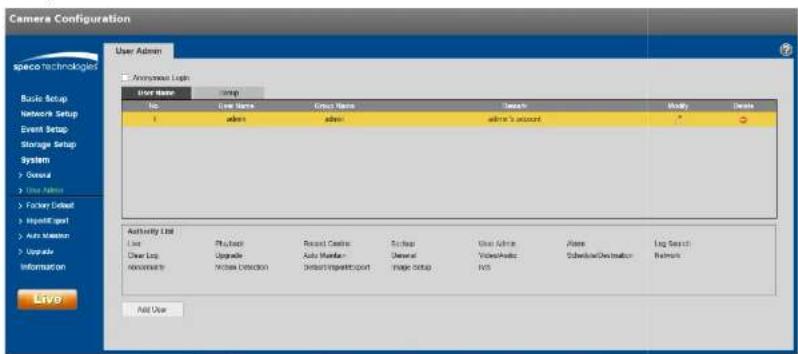
5.5.2 User Admin
-
or user names and user groups, the maximum character length is 91 characters, which can be made up of numbers, letters, underline, hyphen, dot, and @.
- Password can be 8\~92 characters in numbers and letters only.
● A specific user can belong to only one group.
5.5.2.1 %ser Name
See >igure 5-66 for the %ser Name interface.
text_image
Camera Configuration User Admin Anonymed Light Ever Name Group Name Date Modify Delete No Ever Name Group Name Date Modify Delete 1 admin admin admin's account * - + - Use Address Foster Default HyperExport Auto Mission Upgrade Information LTV9 Authority List Line Physical Recent Castes Scrap View Active Alere Log Search Clear Log Upgrade Auto Master General Video/Video Subscription/Destination Refresh Nonperform Mouse Detection Default/Impairport Image Setup IVS Add Userigure 5-66
Enable anonymous login5if enabled, no username and password are required to view the live stream. Click on Logout on the live view page to go back to the login page.

text_image
Add User User Name Must Password The password needs to contain at least 1 character! Weak OK Strong Confirm Password Group adults Remark Authority List All Live Playback Record Control Backup Save Canceligure 5-67
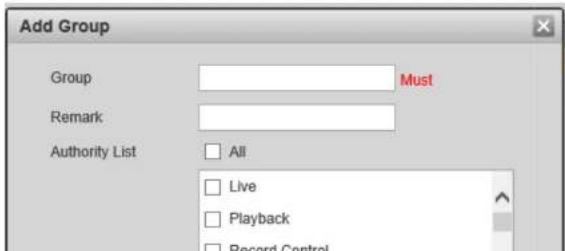
5.5.2.2 Group
The group management interface is shown as in >igure 5-68.

text_image
Camera Configuration User Admin Space Technologies Analyze Log: User Name Group No Sgroup Name Speech Identity Crads 1 SGTTM sense/nnstrat group ? 2 SMC sina group > Authority List Low Flashback Record Control Backup User Adson Alarm Lug Search Clear Log Upgrade Auto Make Size Camera Video/Studio Chassis/Disclosure Notes Abnormality Motion Database Busability per Export Image Setup ByS Auto Groupigure 5-68
Add group5 See >igure 5-69.
Enter the group name and then check the applicable boxes for the rights of the group.
text_image
Add Group Group Must Remark Authority List All Live Playback Record Control5.5.3 Factory Default
The factory default interface is shown in >igure 5-78.
The "Default" option resets every setting of the device while the "Keep Network Settings" option retains pertinent network setup information of the device.

text_image
Camera Configuration speco Technologies Factory Default Default Five Network Setup Basic Setup Network Setup Event Setup Storage Setup System > User > Use Auto > Factory Email > InputCount > AutoTooth > Update Information Liveigure 5-78
5.5.4 Import/Export
The interface is shown in >figure 5-71. This can be used to set up multiple devices of the same model with the same system configuration.

text_image
Camera Configuration ImportExport speco Technologist Basic Setup Network Setup Event Setup Storage Setup Setup Path Event Event| Parameter >unction | |
| Import | Import a configuration file to the device. |
| Export | Export the current configuration of the device to the local PC. |
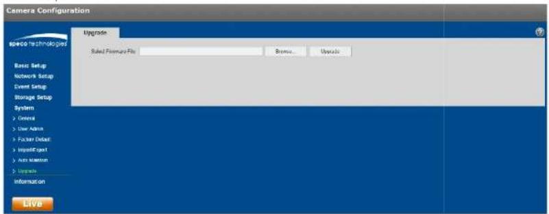
5.5.5 Upgrade
The upgrade interface is shown in >igure 5-72. >irmware of the device can be updated here.
Select the applicable firmware file (file extension is ".bin") and then click the %pgrade button to begin the firmware update.
text_image
Camera Configuration Upgrade Select Forestry File Browse... Upgrade Basic Setup Network Setup Event Setup Storage Setup System > General > User Admin > Follower Detail > ImpulseExpert > Auto Version > Upgrade Information Liveigure 5-72
5.6 Information
5.6.1 Version
The version interface is shown in >igure 5-79.
In this section, the model number, firmware version and date, serial number of the device, and tech support contact information are shown.

text_image
Camera Configuration Version Device Type: CHUBM Software Version: 2.46.9881.1.P, Build Tools 2017 T4.46 WSP Version: 5.2.1388722 DHVP Version: 2.42 SPV: 00037871560 system/Phone: 1-030-045-5516 serverEmail: lchrcapsc@www.shccb.com 2017 Space Technologies, All rights reserved. Liveigure 5-79
5.6.2 Log
See >igure 5-74 for the system log interface.

text_image
Camera Configuration Log space technologies Start time: 10-12-2017 04 23 63 ms End time: 10-12-2017 04 23 63 ms Type: All Search Back Setup Network Setup Event Setup Sensor Setup System Inferonics T Values No Log User Date Name Event| Parameter >unction | |
| Start time | Set the start time of the requested log. |
| End time | Set the end time of the requested log. |
| Type | Select the type of information to display. |
| Log information | Select one item to view detailed information about the entry. |
| Backup | Can be used to back up log files to the PC. |
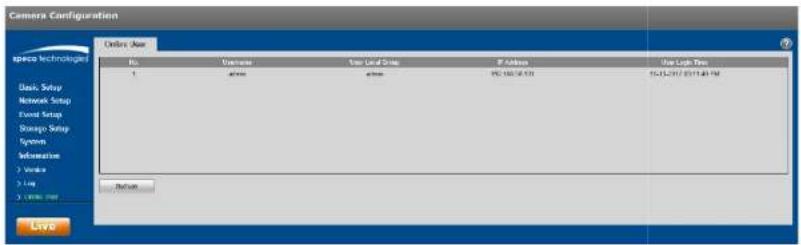
5.6.3 Online User
The online user interface is shown in >igure 5-75.
Information about all users who are currently logged into the device is shown.
text_image
Camera Configuration Online User No. Universe User Local Setup IP Address User Light Time Basic Setup Network Setup Event Setup Storage Setup System Information 1.Virtals 2.Lay 3.Little Web Beforeigure 5-75
Speco Technologies
200 New +ighway
Amityville, NY 11701
Phone: 631-957-8700
Email: techsupport@specotech.com
Web: http://www.specotech.com