WDRB11H - Security Camera Speco Technologies - Free user manual and instructions
Find the device manual for free WDRB11H Speco Technologies in PDF.

User questions about WDRB11H Speco Technologies
0 question about this device. Answer the ones you know or ask your own.
Ask a new question about this device
Download the instructions for your Security Camera in PDF format for free! Find your manual WDRB11H - Speco Technologies and take your electronic device back in hand. On this page are published all the documents necessary for the use of your device. WDRB11H by Speco Technologies.
USER MANUAL WDRB11H Speco Technologies
(Outdoor IR Dome Camera)
WDRD20H
(Indoor IR Dome Camera)
WDRB11H
(Outdoor Bullet Camera with mount plate)
WDRD11H
(Outdoor Dome Camera)
WDD2411
Precautions
① Contents......1
- Precautions....2, 3
Safety Instructions 4
● Package Contents......5
● Camera Installation....6-15
Specifications....16-21
● Camera Dimension 22-24
Features......25
Precautions
Do not install the camera in extreme temperature conditions.

natural_image
Cartoon illustration of a UFO emitting flames with a cloud above (no text or symbols)Only use the camera under conditions where temperatures are between -10°C and +50°C. Be especially careful to provide ventilation when operating under high temperatures.
Do not install the camera under unstable lighting conditions.

Severe lighting change or flicker can cause the camera to work improperly.
Do not touch the front lens of the camera.

This is one of the most important parts of the camera. Be careful not to leave fingerprints on the lens cover.
Never keep the camera pointed directly at strong light.
natural_image
Illustration of a sun shining on a surveillance camera and a helmet, both showing expressive faces (no text or symbols)Do not drop the camera or subject it to physical shocks.

natural_image
Illustration of two surveillance cameras with smokestacks emitting exhaust smoke (no text or symbols)Do not expose the camera to radioactivity.

It can cause malfunctions to occur. If exposed Houston activity has a compromise weatherproof ratings.
will fail.

text_image
CAUTION RISK OF ELECTRIC SHOCK DO NOT OPEN. CAUTION TO REDUCE THE RISK OF ELECTRIC SHOCK DO NOT REMOVE COVER/OR BACKY, NO USER-SERVIEABLE PARTS INDE, REFER SERVICING TO QUALIFIED SERVICE PERSONNEL. ISO14001 CE FC
The lightning flash with an arrowhead symbol, within an equilateral triangle is intended to alert the user to the presence of uninsulated dangerous voltage within the product's enclosure that may be of sufficient magnitude to constitute a risk of electric shock to persons.

The exclamation point within an equilateral triangle is intended to alert the user to the presence of important operating and maintenance (servicing) instructions in the literature accompanying the appliance.
In USA and Canada, Use Class 2 Power Supply Only
INFORMATION - This equipment has been tested and found to comply with limits for a Class A digital device, pursuant to part 15 of the FCC Rules & CE Rules. These limits are designed to provide reasonable protection against harmful interference when the equipment is operated in a commercial environment. This equipment generates, uses, and can radiate radio frequency energy and, if not installed and used in accordance with the instruction manual, may cause harmful interference to radio communications. Operation of this equipment in a residential area is likely to cause harmful interference in which case the user will be required to correct the interference at their own expense.
Safety Instructions
Precautions for use
① This camera should be installed by qualified personnel only
There are no user serviceable parts inside
- Do not disassemble this camera other than to make initial adjustments
- Use a UL approved regulated 24 volt AC or 12 volt DC power supply
- Use appropriate low voltage power cable to prevent fire or electrical shock
- Please insure that your installation area can support the weight of the camera
Please handle this camera carefully :
Do not use a strong or abrasive detergent when cleaning the camera
- Do not install near cooling or heating device
Package Contents
Please make sure that the following items are included in the Package:
1) WDRB10H
• 1 Video Test Connector, Power Jack
• 1 Focus Adjustment
- 1 Bracket Base
• 1 Wrench
- Set Screw
- 4 Tapping Screws 4x25
- 4 Hexagon Socket Screws M5x10
2) WDRD10H
• 1 Video Test Connector, Power Jack
• 1 Chameleon Cover
- 1 Wrench
- Set Screw
- 3 Tapping Screws 4x40
- 1 Hexagon Socket Screw M4x8
3) WDRD20H
- 1 Video Test Connector, Power Jack
• 1 Chameleon Cover - Set Screw
- 3 Tapping Screws 4x25
4) WDRB11H
• 1 Video Test Connector, Power Jack
- 1 Bracket Base
- 2 Wrenches
- Set Screw
CAMERA INSTALLATION
CONNECT POWER CABLE
- WHEN USING 12 VOLTS DC (constant voltage 500 mA)

text_image
Power Input :RED Center : (+) DC 12V Power Supply- WHEN USING 24 VOLTS AC (40 Volt Amps)

text_image
RED(+) BLACK:(-) AC 24V Power Supply- CONNECT VIDEO CABLE
- CONNECT BNC CABLE TO THE BNC JACK.

CAMERA INSTALLATION
Compatibility
1) WDRB10H
text_image
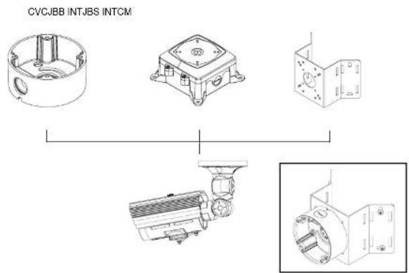
INTCM INTJBS CVCJBB2) WDRD10H / WDRD20H
CVCJBD INTPMDFM INTCMINTWM
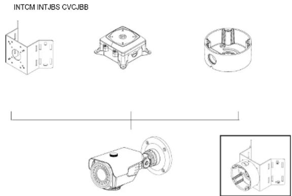
CAMERA INSTALLATION
Compatibility
3) WDRB11H
text_image
CVCJBB INTJBS INTCM4) WDRD11H
CVCJBD INTPMDFM INTCMINTWM

CAMERA INSTALLATION
Compatibility
5) WDRD21H / WDRD21HW
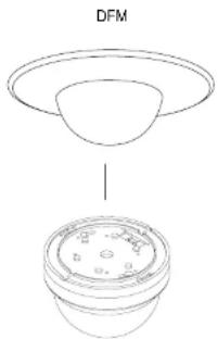
text_image
DFMCAUTION : The installation instructions in this manual are for use by qualified service personnel only. To reduce the risk of electric shock, do not perform any servicing other than that contained in the operating instructions unless you are qualified to do so.
CAMERA INSTALLATION
- WDRB10H
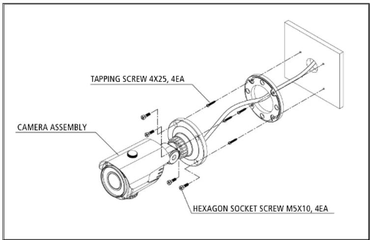
text_image
TAPPING SCREW 4X25, 4EA CAMERA ASSEMBLY HEXAGON SOCKET SCREW M5X10, 4EACAMERA INSTALLATION
- WDRD10H

text_image
BASE ASSEMBLY TAPPING SCREW 4X25, 3EA DOME COVER ASSEMBLYCAMERA INSTALLATION
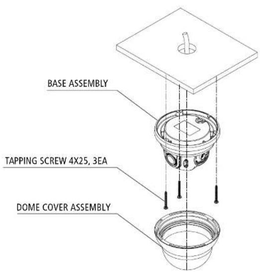
- WDRD20H

text_image
BASE ASSEMBLY TAPPING SCREW 4X25, 3EA DOME COVER ASSEMBLYCAMERA INSTALLATION
- WDRB11H
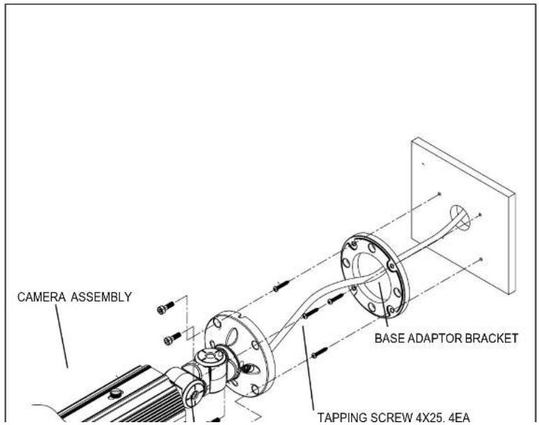
text_image
CAMERA ASSEMBLY BASE ADAPTOR BRACKET TAPPING SCREW 4X25.4EACAMERA INSTALLATION
- WDRD11H
text_image
BASE ASSEMBLY TAPPING SCREW 4X25, 3EA DOME COVER ASSEMBLYCAMERA INSTALLATION
- WDRD21H / WDRD21HW
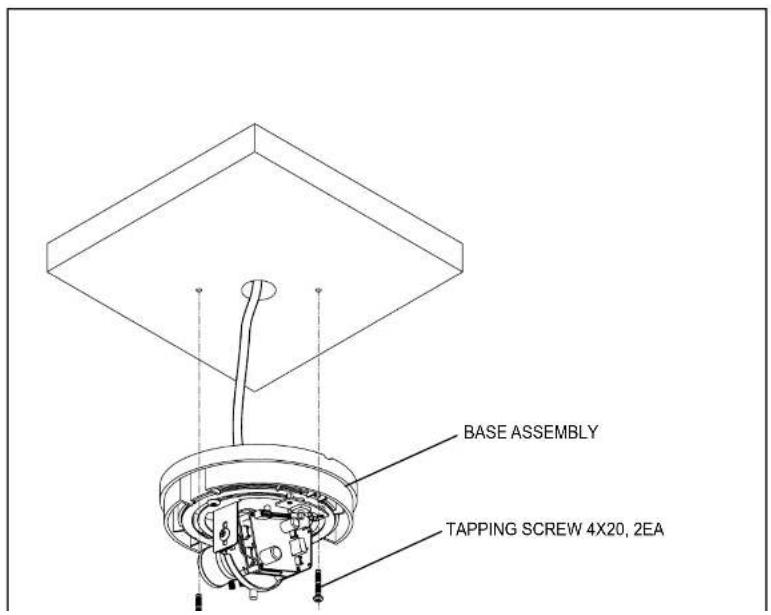
text_image
BASE ASSEMBLY TAPPING SCREW 4X20, 2EASpeco Technologies
(Outdoor IR Bullet Camera)
DC Auto Iris Varifocal Lens 2.8-12mm

natural_image
Exterior view of a security camera (no visible text or symbols)WDRB10H

SPECIFICATIONS
| MODEL | WDRB10H |
| Image Sensor | 1/3" SONY HAD CCD 960H (DUAL SCAN) |
| TV System | NTSC |
| Total Pixels | 1,028(H) x 508(V) |
| Effective Pixels | 976(H) x 494(V) |
| Scanning System | 2:1 Interlace |
| Synchronization | Internal |
| O.S.D | Available |
| BLC / HLC | ON/OFF |
| Horizontal Resolution | 700 TV Lines |
| S/N (Y Signal) | 52dB (AGC off, Weight on) |
| Minimum Illumination | 0.000006LUX(IR LED ON) |
| White Balance | ATW(1,800K – 10,500K) / PUSH / USER1 / USER2 / ANTI CR / MANUAL / PUSH LOCK |
Speco Technologies
(Outdoor IR Dome Camera)
DC Auto Iris Varifocal Lens 2.8-12mm

natural_image
Close-up of a metallic security camera with visible lens and control buttons (no text or symbols)WDRD10H

SPECIFICATIONS
| MODEL | WDRD10H |
| Image Sensor | 1/3" SONY HAD CCD 960H (DUAL SCAN) |
| TV System | NTSC |
| Total Pixels | 1,028(H) x 508(V) |
| Effective Pixels | 976(H) x 494(V) |
| Scanning System | 2:1 Interlace |
| Synchronization | Internal |
| O.S.D | Available |
| BLC / HLC | ON/OFF |
| Horizontal Resolution | 700 TV Lines |
| S/N (Y Signal) | 52dB (AGC off, Weight on) |
| Minimum Illumination | 0.000006LUX(IR LED ON) |
| White Balance | ATW(1,800K – 10,500K) / PUSH / USER1 / USER2 / ANTI CR / MANUAL / PUSH LOCK |
Speco Technologies
(Indoor IR Dome Camera)
DC Auto Iris Varifocal Lens 2.8-12mm

natural_image
Close-up of a black-and-white surveillance camera with a central lens (no visible text or symbols)WDRD20H

SPECIFICATIONS
| MODEL | WDRD20H |
| Image Sensor | 1/3" SONY HAD CCD 960H (DUAL SCAN) |
| TV System | NTSC |
| Total Pixels | 1,028(H) x 508(V) |
| Effective Pixels | 976(H) x 494(V) |
| Scanning System | 2:1 Interlace |
| Synchronization | Internal |
| O.S.D | Available |
| BLC / HLC | ON/OFF |
| Horizontal Resolution | 700 TV Lines |
| S/N (Y Signal) | 52dB (AGC off, Weight on) |
| Minimum Illumination | 0.000006LUX(IR LED ON) |
| White Balance | ATW(1,800K – 10,500K) / PUSH / USER1 / USER2 / ANTI CR / MANUAL / PUSH LOCK |
Speco Technologies
(Weatherproof Bullet Camera with mount plate)
DC Auto Iris Varifocal Lens 2.8-12mm
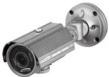
natural_image
Exterior view of a metallic security camera with mounting flange (no text or symbols visible)WDRB11H

SPECIFICATIONS
| MODEL | WDRB11H |
| Image Sensor | 1/3" SONY HAD CCD 960H (DUAL SCAN) |
| TV System | NTSC |
| Total Pixels | 1,028(H) x 508(V) |
| Effective Pixels | 976(H) x 494(V) |
| Scanning System | 2:1 Interlace |
| Synchronization | Internal |
| O.S.D | Available |
| BLC / HLC | ON/OFF |
| Horizontal Resolution | 700 TV Lines |
| S/N (Y Signal) | 52dB (AGC off, Weight on) |
| Minimum Illumination | 0.000006LUX |
| White Balance | ATW(1,800K – 10,500K) / PUSH / USER1 / USER2 / ANTI CR / MANUAL / PUSH LOCK |
Speco Technologies
(Weatherproof Dome Camera with Chameleon™ Cover)
DC Auto Iris Varifocal Lens 2.8-12mm
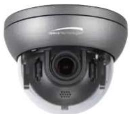
natural_image
Close-up of a security camera with lens and control panel (no visible text or symbols)WDRD11H

SPECIFICATIONS
| MODEL | WDRD11H |
| Image Sensor | 1/3" SONY HAD CCD 960H (DUAL SCAN) |
| TV System | NTSC |
| Total Pixels | 1,028(H) x 508(V) |
| Effective Pixels | 976(H) x 494(V) |
| Scanning System | 2:1 Interlace |
| Synchronization | Internal |
| O.S.D | Available |
| BLC / HLC | ON/OFF |
| Horizontal Resolution | 700 TV Lines |
| S/N (Y Signal) | 52dB (AGC off, Weight on) |
| Minimum Illumination | 0.000006LUX |
| White Balance | ATW(1,800K – 10,500K) / PUSH / USER1 / USER2 / ANTI CR / MANUAL / PUSH LOCK |
Speco Technologies
(Indoor Wall & Ceiling Mount Dome Camera)
DC Auto Iris Varifocal Lens 2.8-12mm

natural_image
Close-up of a black surveillance camera with a lens (no visible text or symbols)WDRD21H

SPECIFICATIONS
| MODEL | WDRD21H |
| Image Sensor | 1/3" SONY HAD CCD 960H (DUAL SCAN) |
| TV System | NTSC |
| Total Pixels | 1,028(H) x 508(V) |
| Effective Pixels | 976(H) x 494(V) |
| Scanning System | 2:1 Interlace |
| Synchronization | Internal |
| O.S.D | Available |
| BLC / HLC | ON/OFF |
| Horizontal Resolution | 700 TV Lines |
| S/N (Y Signal) | 52dB (AGC off, Weight on) |
| Minimum Illumination | 0.000006LUX |
| White Balance | ATW(1,800K – 10,500K) / PUSH / USER1 / USER2 / ANTI CR / MANUAL / PUSH LOCK |
Speco Technologies
(Indoor Wall & Ceiling Mount Dome Camera)
DC Auto Iris Varifocal Lens 2.8-12mm

natural_image
Close-up of a security camera with visible lens and camera (no text or symbols)WDRD21HW

SPECIFICATIONS
| MODEL | WDRD21 HW |
| Image Sensor | 1/3" SONY HAD CCD 960H (DUAL SCAN) |
| TV System | NTSC |
| Total Pixels | 1,028(H) x 508(V) |
| Effective Pixels | 976(H) x 494(V) |
| Scanning System | 2:1 Interlace |
| Synchronization | Internal |
| O.S.D | Available |
| BLC / HLC | ON/OFF |
| Horizontal Resolution | 700 TV Lines |
| S/N (Y Signal) | 52dB (AGC off, Weight on) |
| Minimum Illumination | 0.000006LUX |
| White Balance | ATW(1,800K – 10,500K) / PUSH / USER1 / USER2 / ANTI CR / MANUAL / PUSH LOCK |
CAMERA DIMENSION
1) WDRB10H
text_image
3.94° dia 3.94° dia
text_image
8.27" 4.72" 100 100 100M2) WDRD10H
3.94" dia
CAMERA DIMENSION
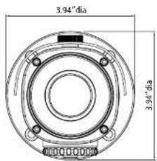
3) WDRD20H
natural_image
Cross-sectional diagram of a mechanical or electrical component with no visible text or symbols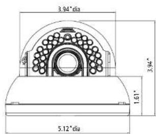
text_image
3.94° dia 3.94° 1.61" 5.12° dia4) WDRB11H
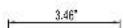

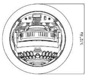
CAMERA DIMENSION
5) WDRD11H
natural_image
Technical line drawing of a circular mechanical component with internal components and mounting holes (no text or symbols)
text_image
3.94° dia 3.94" 1.61" 5.12° dia6) WDRD21H / WDRD21HW


FEATURES
2D.3DNR Filtering Method of Newly Advanced DNR Function
Newly developed 2D filtering enhances Digital Noise reduction at low light levels. 2D Filtering of the Video Signal Optimises the Signal to Noise ratio.
High Resolution
The combination of a Sony Super HAD CCD image sensor and DNR DSP provides an excellent resolution of 700 TV lines.
Wide Dynamic Range
WDR is a powerful and ultra advanced technology that captures cleaner and superior high resolution pictures even where the images appear dark because there is a strong back light present.
High Spotlight BLC Function
Users Can Adjust and Select the Special Required Area to Observe the Target Object Under the Strong Spots of Light Exist.
Menu Set Up (SPECO TECH 1/3)
Menu items can be selected by using the OSD buttons of the camera
- Press the Set Up button.
* The Set Up menu will be displayed on the monitor.

text_image
SPECO TECH 1/3 LENS AUTO SHUTTER/AGC AUTO PICT ADJUST WHITE BAL ANTI CR WDR 2D.3DNR NEXT EXIT SAVE ALL- Move and select the required function using the Up and Down button.
* Move the arrow indicator Up or Down to select the desired feature by pressing the Up or Down button.
- Change menu settings using the Left or Right button.
* Available values or Status are displayed by pressing the Left or Right buttons.
Press the button until desired value / status is displayed.
- After Changing the setting move the arrow indicator to EXIT and press the
SET button to EXIT.
NOTE
* Move to the available submenu by moving ←arrow to desired feature.
Lens
This function is used to set the mechanical iris of the lens.
- Move the arrow indicator to Lens using the Up and Down buttons on the Set Up menu screen.
- Select the mechanical iris type by pressing the left or right button between Manual and Auto.
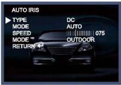
text_image
AUTO IRIS TYPE DC MODE AUTO SPEED 075 MODE OUTDOOR RETURN- Set DC or Video by selecting type on the Auto Iris screen.
- Press the RETURN to return to the SETUP menu.
Shutter/AGC
This function is used to select Automatic or Manual shutter speed control.
- On the Set Up menu screen select SHUTTER/AGC by using the Up or Down button.
- Select the desired shutter mode by pressing the Left or Right button
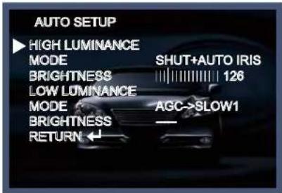
text_image
AUTO SETUP ► HIGH LUMINANCE MODE SHUT+AUTO IRIS BRIGHTNESS 126 LOW LUMINANCE MODE AGC->SLOW1 BRIGHTNESS — RETURN ←HIGH LUMINANCE
* MODE : Shutter is fixed at 1/60, 1/50 and average brightness maintains
* BRIGHTNESS : Adjust the brightness level 0\~255 by pressing the left or the right button.
LOW LUMINANCE
* MODE
- OFF : AGC and SLOW(SENSE-UP) OFF
- AGC : AGC ON and SLOW(SENSE-UP) OFF.
Enter the LOW LUMINANCE SETUP and adjust GAIN level by pressing the left or the right button.
- SLOW(SENS-UP) : SLOW(SENSE-UP) ON and AGC OFF.
Enter the LOW LUMINANCE SETUP and adjust SLOW(SENSE-UP) level by pressing the left or the right
NOTE
* AGC (Auto Gain Control)
A higher gain increases brightness but also increases noise.
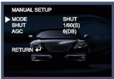
text_image
MANUAL SETUP ► MODE SHUT SHUT 1/60(S) AGC 6(DB) RETURN ←* SHUTTER : Adjust the shutter level 1/60, FLK, 1/100, 1/250, 1/500, 1/1000, 1/2000, 1/4000, 1/10000 (S) adjust the red color GAIN by pressing the left or the right button.
* Adjust the AGC level 6, 12, 18, 24, 30, 36, 42, 44.8, (DB) by pressing the left or the right button.
* RETURN : Move previous page.
PICT Adjust
Move the cursor to PICT ADJUST press the SET button.
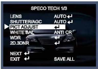
text_image
SPECO TECH 1/3 LENS AUTO SHUTTER/AGC AUTO PICT ADJUST WHITE BAL ANTI CR WDR 2D.3DNR NEXT ← EXIT ← SAVE ALL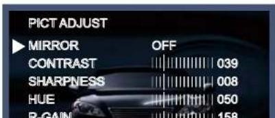
text_image
PICT ADJUST MIRROR OFF CONTRAST 039 SHARPNESS 008 HUE 050 R-GAIN 158* B-GAIN : Adjust the blue color GAIN 0\~255 by pressing the left or the right button.
* RETURN : Move previous page.
White Balance
This function is used to set the white balance operation mode.
- Move the arrow indicator to WHITE BAL on the SETUP menu screen using the Up and Down button.
- Select the desired mode by using the Left or Right button.

text_image
SPECO TECH 1/3 LENS AUTO SHUTTER/AGC AUTO PICT ADJUST WHITE BAL ANTI CR WDR 2D.3DNR NEXT ← EXIT ← SAVE ALL* ATW : Auto tracking white, normal environment setting under fluorescent lamp or outdoors.
- SPEED : Select the start point of auto tracking speed and time by pressing the left or the right button.
- DELAY CNT : Select the start point of Auto tracking speed and time by pressing the left or the right button.
- ATW FRAME : Set up the frame magnification by pressing the left or the right button.
- ENVIRONMENT: It improves color temperature chase accuracy in accordance with environmental set-up. Select the environment by pressing the left or the right button.
- RETURN : Select return to save the changes in the ATW menu and return to the SETUP menu.
* PUSH : Regardless of subject condition, adjust white balance. Always control locking mode with full-in frame, white color as set point.
* USER1 WB: The gain values for the outdoor fixed mode are used as the adjustment items of USER1 on the internal OSD menu.
* USER2 WB: The gain values for the fluorescent light fixed mode are used as the adjustment items of USER2 on the internal OSD menu.
* ANTI CR : COLOR rolling control
* MANUAL WB: The B and R gain values for manual WB are set on this screen.
- LEVEL UP : Induce change to high color temperature side.
- LEVEL DOWN : Induce change to low color temperature side.
* PRESET : Reset the adjusted color temperature side.
WDR(Wide Dynamic Range)
* WDR : The wide dynamic range (WDR) function of a camera is intended to provide clear images even under back light circumstances where intensity of illumination can vary excessively, namely when there are both very bright and very dark areas simultaneously in the field of view of the camera.

text_image
SPECO TECH 1/3 LENS AUTO SHUTTER/AGC AUTO PICT ADJUST WHITE BAL ANTI CR WDR 2D.3DNR NEXT EXIT SAVE ALL

natural_image
Interior view of a modern building with glass windows and trees, showing a person holding an object (no visible text or symbols)WDR OFF WDR ON

natural_image
Interior view of a modern glass building with people standing near a window (no visible text or symbols)2D.3DNR
2DNR function does Y,C filtering and decrease noise.
The level of 3DNR noise removal mode is getting higher, noise removal effect will be good, but ghost effect may be shown up. Select OFF, LOW, MIDLOW, MID, MIDHIGH, HIGH by pressing the left or the right button.
SPECO TECH 1/3
NEXT
Move to next page.(SETUP MENU 2/3)
EXIT
Press the SET button in the EXIT menu to save the current settings and exit the SETUP menu.
SAVE ALL
This function is used to save the various settings of the internal OSD menu in the EEPROM together.
SAVE ALL is always displayed on the bottom line of the top menu. Its display position cannot be changed.
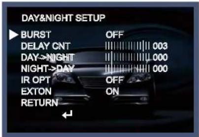
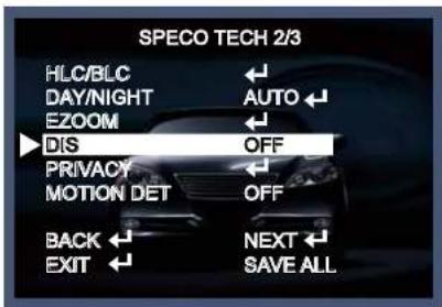
Menu Set Up (SPECO TECH 2/3)
Menu items can be selected by using the OSD buttons of the camera
- Press the Set Up button.
* The Set Up menu will be displayed on the monitor.
text_image
SPECO TECH 2/3 HLC/BLC DAY/NIGHT AUTO EZOOM DIS OFF PRIVACY MOTION DET OFF BACK NEXT EXIT SAVE ALL- Move and select the required function using the Up and Down button.
* Move the arrow indicator Up or Down to select the desired feature by pressing the Up or Down button.
- Change menu settings using the Left or Right button.
* Available values or Status are displayed by pressing the Left or Right buttons. Press the button until desired value / status is displayed. - After Changing the setting, move the arrow indicator to EXIT and press the SET button to EXIT.
NOTE
* Move to the available submenu by moving

arrow to desired feature.
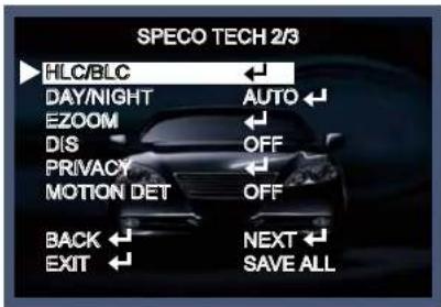
HLC/BLC
This function is used to set the mechanical iris of the lens.
- Move the arrow indicator to Lens using the Up and Down buttons on the Set Up menu screen.
- Select the mechanical iris type by pressing the left or right button between Manual and Auto.
text_image
HLC/BLC HLC OFF CLIP LEVEL 000 SCALE 010 BLC RETURN ↕* HLC : HLC, control and mask process for a strong light source. Select OFF, ON, AUTO by pressing the left or the right button.
* CLIP LEVEL : Adjust the Brightness mask level by pressing the left or the right button.
* SCALE : Adjust the Brightness signal control level by pressing the left or the right button.
* BLC : Turn off or on the Back light compensation
* RETURN : Move previous page.
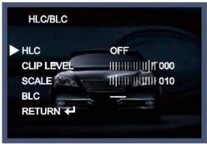
DAY/NIGHT
text_image
DAY&NIGHT SETUP BURST OFF DELAY CNT 003 DAY→NIGHT 000 NIGHT→DAY 000 IR OPT OFF EXTON ON RETURN* BURST : Adjust color signal ON/OFF in night(B/W) mode.
* DELAY CNT : Adjust the DELAY time level 0\~255 for day&night switch by pressing the left or the right button.
* DAY→NIGHT : Adjust the DAY→NIGHT switch level 0\~255 by pressing the left or the right button.
* NIGHT→DAY : Adjust the NIGHT→DAY switch level 0\~255 by pressing the left or the right button.
* IR OPT : If you select AUTO, SMART IR function will be applied to the whole field.

text_image
IR OPTIMIZER SMART IR CENTER LEVEL 015 ATR WD-EX ON RETURN ↕→ AUTO: The mode will automatically switches to COLOR in normal condition and switches to BW mode when ambient illumination is low.
Press the SET button to set the switching time or D→N(AGC), N→D(AGC) in AUTO mode.
- SMART IR : adjust the division field level by pressing the left or the right button.
TOP : 000\~114 Level adjustable
BOTTOM : 000\~122 Level adjustable
LEFT:000\~223 Level adjustable
RIGHT : 000\~239 Level adjustable

natural_image
Black-and-white photo of a person standing in a dimly lit room with visible furniture and lighting (no text or symbols)
natural_image
Black-and-white photo of a person standing indoors near a ladder (no visible text or symbols)SMART IR ONSMART IR OFF
- LEVEL : Strength control level by pressing the left or the right button.
-
ATR WD-EX : ATR WD-EX works only in B/W mode. (IR LED linkage)
-
DELAY CNT : Adjust the DELAY time level 0\~255 for day&night switch by pressing the left or the right button.
- POLARITY : HIGH, LOW select the active high or low of outside input signal reversal
- RETURN : Move previous page.
EZOOM
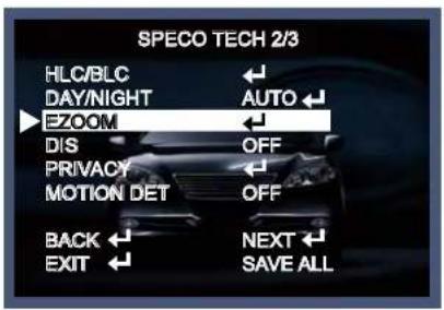
text_image
SPECO TECH 2/3 HLC/BLC DAY/NIGHT EZOOM DIS PRIVACY MOTION DET BACK EXIT NEXT SAVE ALL
DIS(Digital Image Stabilizer)
Image stabilization
text_image
SPECO TECH 2/3 HLC/BLC DAY/NIGHT EZOOM DIS OFF PRIVACY MOTION DET OFF BACK EXIT NEXT SAVE ALLPRIVACY
Hide an area you want to hide on the screen.

text_image
PRIVACY ▶ AREA SEL 1/15 MODE OFF POSITION COLOR TRANSP MOSAIC RETURN ←* AREA SEL : Selects the mask frame to be adjusted.
* MODE : Adjust AREA SEL function ON or OFF.
* POSITION : PRIVACY MASK field set-up
* COLOR : Sets the colors of the mask frames.
It selects the palette values below (where m: 0-7, color setting - 1) for settings 1 to 8.
* TRANSP : Sets the transparency ratio of the mask frames.
The same transparency ratio value is set for all the mask frames.
* MOSAIC : Sets the mask frame mosaic function to ON or OFF.
OFF: Mosaic function OFF
ON: Mosaic function ON

text_image
MOTION DET ► DETECT SENSE 111 BLOCK DISP OFF DETECT AREA ← MONITOR AREA ← RETURN ←* DETECT SENSE : Motion detection strength level 0\~127 control
* BLOCK DISP : Controls the ON/OFF status of the motion detection block display.
* DETECT AREA : BLOCK field set-up
* MONITOR AREA : Sets whether to use the monitoring frames.
- AREA SEL 1/4 : Selects the monitoring frame be set.
- MODE
OFF: The monitoring frames are not used.
ON: The monitoring frames are used.
- TOP : Sets the top side of the monitoring frame selected by the AREA SEL parameter.
- BOTTOM: Sets the bottom side of the monitoring frame selected by the AREA SEI parameter
EXIT
Press the SET button in the EXIT menu to save the current settings and exit the SETUP menu.
NEXT
Move to next page.(SETUP MENU 3/3)
SAVE ALL
This function is used to save the various settings of the internal OSD menu in the EEPROM together.
SAVE ALL is always displayed on the bottom line of the top menu. Its display position cannot be changed.
Menu Set Up (SPECO TECH 3/3)
Menu items can be selected by using the OSD buttons of the camera
- Press the Set Up button.
* The Set Up menu will be displayed on the monitor.
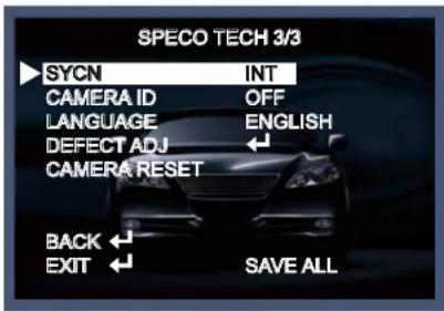
text_image
SPECO TECH 3/3 SYCN INT CAMERA ID OFF LANGUAGE ENGLISH DEFECT ADJ CAMERA RESET BACK SAVE ALL EXIT- Move and select the required function using the Up and Down button.
* Move the arrow indicator Up or Down to select the desired feature by pressing the Up or Down button.
SYNC
INT (Internal Synchronisation)

text_image
SPECO TECH 3/3 SYCN INT CAMERA ID OFF LANGUAGE ENGLISH DEFECT ADJ ← CAMERA RESET BACK ← EXIT ← SAVE ALLCAMERA ID
To select the position where the camera ID should be displayed on the screen.

text_image
CAMERA ID SETUP ABCDEFGHIJKLMNOPQRSTUVWXYZ0123456789-1"#$%&" () -- ¥-- (=)? Ⓞ^*×∛/+ ←→↑↓ CLR_POS RETURN ←* A - )Each user font: A selected character is registered at the position selected by the CAMERA ID cursor when the Enter operation input is performed from the status in which the characters have been selected using the character selection cursor. The camera ID cursor then moves one character to the right.
* ← → ↑ ↓: The camera ID cursor moves in the direction of the arrow when the Enter operation input is performed from the status in which ←, →, ↑ or ↓ has been selected using the character selection cursor.
* CLR: The character selected by the camera ID cursor is cleared when the Enter operation input is performed from the status in which CLR has been selected using the character selection cursor.
LANGUAGE
Selects the language in which to display the internal OSD menu.
The menus can be changed in real time in the selected language.
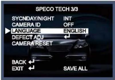
text_image
SPECO TECH 3/3 SYCNDAY/NIGHT INT CAMERA ID OFF LANGUAGE ENGLISH DEFECT ADJ CAMERA RESET BACK ← EXIT ← SAVE ALLDEFECT ADJ
Detection ADJUSTABLE (White pixel detection and compensation mode) 64 Points compensation.

text_image
DEFECT ADJ DETTH 002 DETPGAIN 034 START RETURN ↓* DETTH : In light block situation, if the brightness value of white pixel is low, more white pixel is detected and is high, lower white pixel is detected.
* DETPGAIN : In light block situation, while white spot is being detected, gain level set-up, level is getting higher, more white pixel is detected.
* START: When White pixel compensation is done, SUCCESS will show up on the monitor. EX) When more 64 POINTS are detected, ERROR will show up.
* RETURN : Move previous page.
CAMERA RESET
EXIT
Press the SET button in the EXIT menu to save the current settings and exit the SETUP menu.
BACK
Move to previous page.(SETUP MENU 2/3)
SAVE ALL
This function is used to save the various settings of the internal OSD menu in the EEPROM together.
SAVE ALL is always displayed on the bottom line of the top menu. Its display position cannot be changed.
- Trouble Shooting
| PROBLEM | POSSIBLE CAUSE |
| Nothing appears on the screen. | Check the power cable, power supply output and video connection between the camera and monitor. |
| The image on the screen is dim. | Are the camera lens or the lens glass dirty?Clean the lens / glass with a soft clean cloth.Adjust the monitor controls, as required.If the camera is facing a very strong light, change the camera position.Adjust the lens focus. |
| The image on the screen is dark. | Adjust the contrast control of the monitor.If there is an intermediate device, correctly set the 75Ω/Hi-z. |
| The camera is not working properly and the surface of the camera is hot. | Check the camera is correctly connected to an appropriate regulated power source. |
| Motion Detection | Has MOTION DET been set to ON in the menu? |

LIMITED WARRANTY - VIDEO PRODUCTS
THIS WARRANTY IS VALID ONLY ON PRODUCTS PURCHASED AND USED IN THE UNITED STATES OF AMERICA AND CANADA. THIS WARRANTY APPLIES ONLY TO THE ORIGINAL USER.
SUBJECT TO CONDITIONS AND EXCLUSIONS FOUND BELOW, THIS PRODUCT IS WARRANTED AGAINST MANUFACTURING DEFECTS IN MATERIAL AND WORKMANSHIP FOR THE FOLLOWING PERIOD FOR PARTS AND LABOR:
| SPECO TECHNOLOGIES CAMERAS....5 YEARS |
| SPECO TECHNOLOGIES IP CAMERAS....2 YEARS |
| SPECO PTZ AND VL CAMERAS....1 YEAR |
| SPECO TECHNOLOGIES MONITORS....1 YEAR |
| IR LEDS....90 DAYS |
| DVRs | 3 YEARS |
| NVRs | 3 YEARS |
| BALANCE OF | |
| SPECO TECHNOLOGIES LINE | 1 YEAR |
SPECO TECHNOLOGIES WILL REPAIR OR REPLACE (AT OUR DISCRETION) ANY PARTS FOUND TO BE DEFECTIVE FOR THE WARRANTY PERIOD SPECIFIED. WE WILL PROVIDE A REPLACEMENT FOR ANY DEFECTIVE PART.
CONDITIONS
-
YOU MUST OBTAIN A RETURN AUTHORIZATION (RA) NUMBER FOR ANY MERCHANDISE BEING RETURNED TO SPECO TECHNOLOGIES, WHETHER FOR RETURN/EXCHANGE OR REPAIR, WHETHER IN OR OUT OF WARRANTY.
-
THIS WARRANTY WILL BE HONORED ONLY UPON PRESENTATION OF THE ORIGINAL DATED BILL OF SALE OR SALES SLIP.
-
TRANSPORTATION OF THE PRODUCT TO OUR SERVICE DEPARTMENT IS THE RESPONSIBILITY OF THE USER, REPAIRED OR REPLACED PRODUCT WILL BE RETURNED PREPAID DURING THE WARRANTY PERIOD.
-
SPECO TECHNOLOGIES DOES NOT AUTHORIZE ANY INTERNET OR MAIL ORDER PRODUCT SALES. IF A SPECO TECHNOLOGIES PRODUCT IS PURCHASED FROM AN UNAUTHORIZED DISTRIBUTOR OR OTHER SOURCE, INCLUDING RETAILERS, MAIL ORDER SELLERS AND ONLINE SELLERS. IT WILL NOT BE HONORED OR SERVICED UNDER THE EXISTING SPECO TECHNOLOGIES WARRANTY POLICY ANY SPECO TECHNOLOGIES PRODUCT PURCHASED FROM THESE ONLINE MERCHANTS WILL VOID THE APPLICABLE WARRANTY AND IS INELIGIBLE FOR TECHNICAL SUPPORT. IF YOU HAVE QUESTIONS ABOUT A RESELLER, PLEASE CONTACT SPECO TECHNOLOGIES AT 1-800-645-5518 FOR A LIST OF UNAUTHORIZED DEALERS, VISIT: www.specotech.com/unauthorized.
EXCLUSIONS
-
THIS WARRANTY SHALL NOT COVER ADJUSTMENT OF CUSTOMER OPERATED CONTROLS AS EXPLAINED IN THE APPROPRIATE Model's INSTRUCTION MANUAL OR PRODUCTS WHICH HAVE BEEN ALTERED, ABUSED, OR HAVE MISSING OR ALTERED SERIAL NUMBERS.
-
THIS WARRANTY SHALL NOT APPLY TO UNCRATING, SETUP, INSTALLATION, OR THE REMOVAL AND REINSTALLATION OF PRODUCTS AFTER REPAIR.
-
THIS WARRANTY SHALL NOT APPLY TO REPAIRS OR REPLACEMENTS NECESSITATED BY ANY CAUSE BEYOND THE RESULT OF MANUFACTURE INCLUDING, BUT NOT LIMITED TO, ANY MALFUNCTION, DEFECTS OR FAILURE CAUSED BY OR RESULTING FROM UNAUTHORIZED SERVICE OR PARTS, IMPROPER MAINTENANCE, MODIFICATION OR REPAIR BY THE USER, ABUSE, MISUSE, NEGLECT, ACCIDENT, FIRE, FLOOD, OR OTHER ACTS OF NATURE, INCORRECT LINE VOLTAGE, DAMAGE OR IMAGE BURNS TO TELEVISION PICTURE TUBES CAUSED BY OR ATTRIBUTABLE TO THE USE OF ANY ACCESSORY, ELECTRONICS GAME OR DEVICE, OR DAMAGE CAUSED TO IMAGE PICKUP DEVICES BY EXCESSIVE LIGHT.
- MEMO -
- MEMO -
- MEMO -
speco technologies®
200 New Highway