OB1 - Security Camera Speco Technologies - Free user manual and instructions
Find the device manual for free OB1 Speco Technologies in PDF.

| Type | Security Camera |
| Brand | Speco Technologies |
| Model | OB1 |
| Dimensions | Approx. 3.5 x 3.5 x 6.7 inches |
| Weight | Approx. 1.2 lbs |
| Power Supply | 12V DC, 1A |
| Resolution | 1080p Full HD |
| Night Vision | Up to 30 meters infrared |
| Field of View | 90° horizontal |
| Weatherproof Rating | IP66 |
| Mounting Type | Wall or ceiling mount |
| Video Output | BNC, RCA |
| Main Functions | Motion detection, remote viewing, H.265 compression |
| Security Features | Password protection, HTTPS support |
| Maintenance & Cleaning | Clean lens with soft dry cloth; keep vents free of dust |
| Spare Parts & Repairability | Contact Speco support for replacement parts; do not open cover |
| Included Accessories | Mounting kit, power adapter, user manual |
| Storage | NVR or DVR compatible (not included) |
Frequently Asked Questions - OB1 Speco Technologies
User questions about OB1 Speco Technologies
0 question about this device. Answer the ones you know or ask your own.
Ask a new question about this device
Download the instructions for your Security Camera in PDF format for free! Find your manual OB1 - Speco Technologies and take your electronic device back in hand. On this page are published all the documents necessary for the use of your device. OB1 by Speco Technologies.
USER MANUAL OB1 Speco Technologies
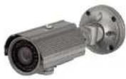
natural_image
Close-up of a gray security camera with mounted lens and flange, set against a textured metal surface (no visible text or symbols)Directions
Be careful not to cause any physical damage by dropping or throwing ONSIP OB1. Especially keep the device out of reach from children.
Do not disassemble ONSIP OB1. No After Service is assumed when disassembled.
Use only the power adapter provided with ONSIP OB1.
Be careful to prevent moisture or water penetration into the unit. Particular attention is needed when installing ONSIP OB1. The screw holes for the installation screws and pipe should be maintained water tight during the whole life time of the product.
All the electrical connection wires running into the unit should be prepared so that water from the outside cannot flow into the unit through the surface of the wires. Penetration of the moisture through the wire for extended period can cause malfunction of the unit or deteriorated image.
Note
This equipment has been tested and found to comply with the limits for a Class a digital device, pursuant to part 15 of the FCC Rules. These limits are designed to provide reasonable protection against harmful interference in a residential installation. This equipment generate, uses and can radiate radio frequency energy and, if not installed and used in accordance with the instructions, may cause harmful interference to radio communications. However, there is no guarantee that interference
Caution
Any changes or modifications to this device could void the warranty.
Revision History
| Date | Revision | Details |
| 2011-11-01 | 1.0 | First manual revision creation. |
Contents
Contents....4
- Introduction 6
1.1. Overview....6
1.2. Specification 7
1.3. Applications of ONSIP OB1....9
- Product Description 10
2.1.Contents 10
2.2. Product Preview 11
2.3. Physical description 12
2.4. Functional Description 14
2.5. Accessories for installation.... 16
- On Site Installation.... 17
3.1. Bracket 17
- Cotting Started 19
ONSIP OB1 Owner's Manual
6-4. Lens Setting 35
6-5. Exposure Setting 36
6-6. White Balance (White Bal) Setting 38
6-7. WDR Setting 39
6-8. Backlight Setting 40
6-9. SPECO DNR Setting 42
6-10. Day/Night Setting 43
6-11. Special Setting 45
6-12. RETURN Setting 50
1. Introduction
1.1. Overview
The ONSIP OB1 is multi-codec (H.264, MJPEG) IP camera (or network camera) built with embedded software and hardware technology. It enables real time transmission of synchronized video of up to D1 and audio data. Remote clients can connect to ONSIP OB1 for the real time video/audio data through various client solutions running on PC or smart device. Real time 2-way communication is available through bidirectional audio communication feature.
Designed to be a stand-alone streaming audio & video transmission device, ONSIP OB1 can be applied to various application area such as video security, remote video monitoring, distance education, video conference or internet broadcasting system.
Vandal proof housing satisfying IP-67 will extend the application area to harsh environment of wide temperature range.
1.2. Specification
| Category | Sub-Category | Details | |
| Video | Compression | H.264 / MJPEG | |
| Resolution | * Refer to the datasheet. | ||
| Camera Module | Mounting Gimbal | 3 Axis Gimbal | |
| Audio(Bi-directional) | Up | 32 Kbps G.726 | |
| Down | 128 Kbps PCM | ||
| Network | Interface | RJ-45, 10/100 Mbps | |
| Access network | Static, DHCP, PPP/PPPoE, uPnP | ||
| Application | RTP, RTSP, SMTP, FTP, HTTP, SDP, NTP, DNS | ||
| I/O | Sensor In | 1 | NC, NO Selectable |
| Relay Output | 0 | N/A | |
| RS-232C | N/A | ||
| Mic/Line In | Selectable in Admin page | ||
| Line Out | 1 V p-p output for amplified speaker | ||
| CVBS output | For temporal use in installation | ||
| Power Supply | PoE | N/A | |
ONSIP OB1 Owner's Manual
| ID and Password protection | ||
| IP filtering for restricting administrative access for audio and bi-audio | ||
| Time management | Sync to PC | Synchronize to PC |
| Manual | Manual time setting | |
| Internet Time Server | Synchronize to Time Server | |
| SDK support | Active-X | |
| HTTP | ||
| Source filter | ||
1.3. Applications of ONSIP OB1
- Security surveillance (buildings, stores, manufacturing facilities, parking lots, banks, government facilities, military, etc.)
- Remote monitoring (hospitals, kindergartens, traffic, public areas, etc.)
• Teleconference (Bi-directional audio conference). Remote Learning, Internet broadcasting
• Weather and environmental observation
2. Product Description
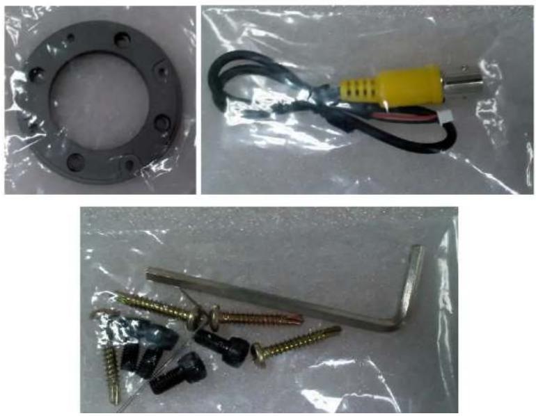
2.1. Contents
The product package contains followings:
| Contents | Description | Remarks |
| ONSIP OB1 | IP camera ONSIP OB1 main unit | |
| Power Adaptor | 12VDC Adaptor | |
| Tools and Mounting Screws | Screws, L-type wrench | |
| CD | Software & User's Guide | |
| Quick Reference Guide | Quick installation guide |
2.2. Product Preview
| ONSIP OB1 | IP-Installer | CMS Software(NVR) |
 |  |  |
| Weather proofBullet IP Camera | PC software to allocate an IP address to the IP Camera | PC software to view and record the A/V streaming data transmitted from IP camera.(Simultaneous support of up to 64 IP cameras) |
2.3. Physical description
2.3.1. External View

text_image
100mm 125mm 88mm 87mm FRONT
text_image
230mm 160mm 80mm Digital Day Night Color Camera 360° 360° 180° SIDERear
Figure 2-1. External view of ONSIP OB1
2.3.2. Connector information

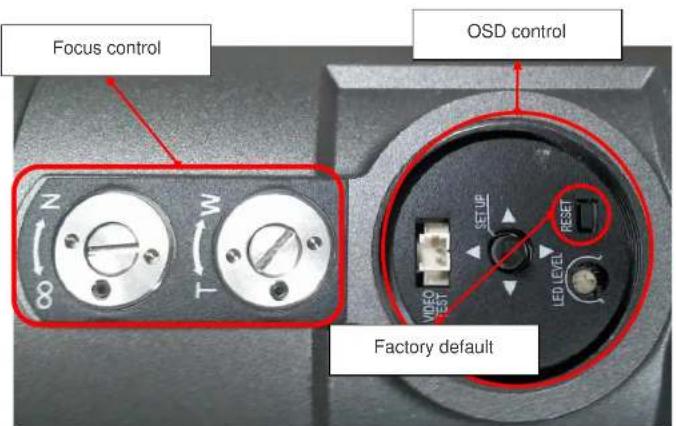
text_image
Focus control N 8 M T OSD control Factory defaultFigure 2-3. Factory Default switch and Video output connector
2.4. Functional Description
• DC 12V: Power input for supplying 12V DC power.
- MIC/LINE IN
Connect external audio source or microphone.
• Line Out
Connect speakers with built in amplifier. Audio from remote site is output through Line out in bi-directional audio mode.
• 100Base-T
100Mbps Ethernet connector (RJ-45)
• Alarm In/Out and Audio In
Used for connecting alarm sensor, microphone and speaker to ONSIP OB1.
| Description | |
| LINE OUT (+) | 1 V p-p audio signal output for amplified speaker. |
| MIC/LINE GND (-) | Ground for audio signals. |
| MIC/LINE IN (+) | Audio input: Can be used either for microphone or applying audio signals from other audio equipment. |
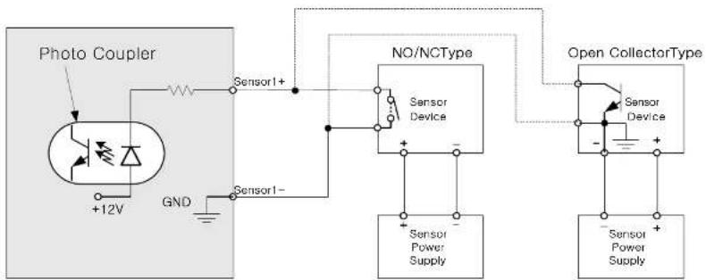
flowchart
graph TD
    A["Photo Coupler"] --> B["Sensor1+"]
    B --> C["NO/NCType"]
    C --> D["Sensor Device"]
    D --> E["Sensor Power Supply"]
    F["Open CollectorType"] --> G["Sensor Device"]
    G --> H["Sensor Power Supply"]
Figure 2-4. SENSOR input and connection of the sensor
• Factory Default Switch
A switch provided for returning the IP camera to factory default state. Open the dome cover to access the switch. Press the switch for a few seconds while power is applied.
natural_image
Close-up of a metallic surface with a curved cutout and textured top (no text or symbols visible)2.5. Accessories for installation
3. On Site Installation
Use Cables and conduits that are suitable for the installation and that are compliant to IP-67. Particular attention should be paid in the installation so that no moisture is allowed to penetrate into the unit through the cables or conduits during the life time of the product. Products of which the internal parts are exposed to moisture because of improper installation are not covered by warranty.
3.1. Bracket

text_image
Sunshield CDS Sensor IR LED DC Auto Iris Varifocal Lens (2.8mm-12mm) Case OSD Control Bracket Base4. Getting Started
Brief information for first time operation of ONSIP OB1 is provided in this chapter.
4.1. PC Requirement
Audio/Video streaming data received from ONSIP OB1 can be displayed or stored in a PC running client programs. Minimum requirement of the PC is described below:
| Recommended | Remark | |
| CPU | Pentium IV 3G above | |
| Main Memory | 1GB above | |
| Operating System* | Windows XP | |
| Web Browser | Internet Explorer 6.0 above | |
| Graphic Card | 64M above | Higher than 1600x1200 |
| Network | 100 Base-T Ethernet |
4.2. Quick Installation Guide
- Connect PC and ONSIP OB1 to network.
1) Prepare a PC to run programs for the installation and video connection (PC is needed to assign IP address to ONSIP OB1)
2) Connect ONSIP OB1 as shown in dotted line in Figure 4-1. The DC power is applied through DC adaptor.
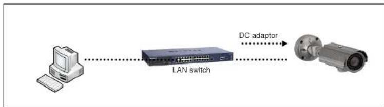
Figure 4-1. Power and network connection
2. Install Speco-NVR
Speco-NVR is a multi-channel CMS program for to IP camera or Video server. Install Speco-NVR on remote PC to connect to these products. It is needed to assign connection information to Speco-NVR program before connection.
Insert the CD provided with product into the PC and install the Speco-NVR.
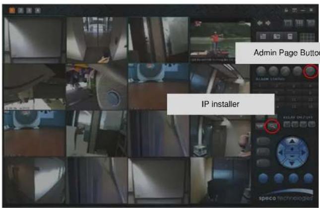
text_image
Admin Page Button IP installer
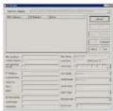
text_image
IP Installer MAC Address IP Address Name No Refresh Set Admin Port Refresh Default Adapter About Exit 1 2 3 4 5 6 7 Net Mode Static System Name Web Port RTSP Port Management Server Clone MAC UPnP Disable UP Static ADSL(PPPoE) Auto(DHCP) IP Address Subnet Mask Gateway DNS1 DNS2 Service Name User Name Password WLAN SSID Auth. Type EncryptType WLAN Key Network Adapter ©Device\WINPF_14580157E-6F24-4AC1-5382-GEED57E3FAB13. Remote video connection to ONSIP OB1
1) Connection through Web Viewer
Web Viewer offers simplest way of video connection to ONSIP OB1. For video connection, enter the IP address of ONSIP OB1 in the URL window of Internet Explorer as:
[e.g.] Port 80
http://172.16.64.133/
Can be omitted the default port of 80
[e.g.] Port 8080
e http://172.16.64.133:8080/

Note: Active-X module should be installed on your PC before actual connection. If your PC is not connected to the internet, you cannot download Active-X module. Most convenient way of installing the Active-X module is installing Speco-NVR which is available from the CD or our web site.
Connection to Admin Page
Basic Control Buttons

text_image
Network Capture Server - Windows, Internet Explorer May 27 10:31:32 Network Capture Server OK OKONSIP OB1 Owner's Manual
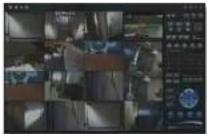
2) Connection through Speco-NVR
Click the camera assignment button for setting camera address. Input the description, address, Ch#, User ID, Password and port and then click the save button. After assignment procedure, you must click the SAVE button. You can see the live video when you click the live view button as below. When you exit Speco-NVR, you have to input the ID/PW, admin/1234. Details for the Speco-NVR can be found in [Speco-NVR User's Guide].
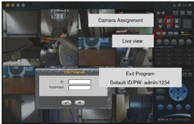
text_image
Camera Assignment Live view Exit Program Default ID/PW: admin/1234
Camera Assignment
4. Additional settings through connection to the Admin Page
All the parameters of new IP camera fallows factory default values. For more sophisticated target application it is needed to change parameters. The admin page can be connected through
"http://IP_address:HTTP_port_number"/admin.htm
It is needed to enter ID and password of the administrator. Default ID and password are admin, 1234. It is highly recommended to change the ID and password to prevent illegal access to the IP camera. For more detailed information, please refer to the [Configuration_Guide] Guide.
5. Trouble Shooting
5.1. No power is applied
- In case of DC adaptor
If PoE is not applied, the power and network connection should be made through separate cables. It is recommended to use DC adaptor supplied by provider for the feeding of the power. In case of replacing the DC power supply, make sure that the power supply meets with the power requirement of the IP camera to prevent damage or malfunction.
5.2. Cannot connect to the Video
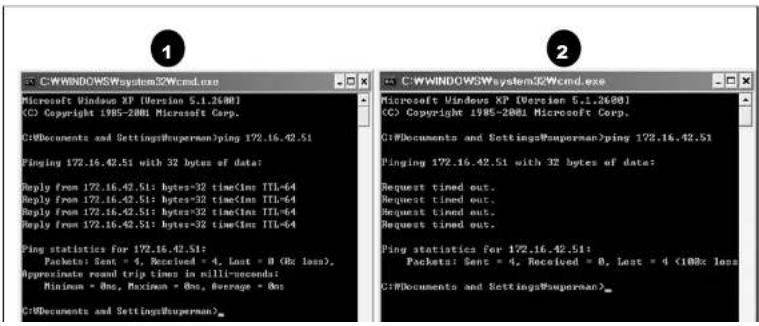
Check the status of the network connection through PING test.
Try the following on your PC:
- Start > Run > Cmd > Ping IP address (Ex : Ping 172.16.42.51)
- If "Reply from \~" message is returned (① in the figure below), the network connection is in normal state. Try connection to the video again. If the problem persists, or refer to other trouble shooting notes.
- If "Request timed out" message is returned. (② in the figure below), the network connection or network setting is not in normal state. Check the network cable and settings.
text_image
C:\WINDOWSWsystem32\Wcmd.exe Microsoft Windows XP (Version 5.1.2600) (C) Copyright 1985-2001 Microsoft Corp. C:\Documents and Settings\superman\ping 172.16.42.51 Pinging 172.16.42.51 with 32 bytes of data: Reply from 172.16.42.51: bytes=32 time(Inn TTL=64 Reply from 172.16.42.51: bytes=32 time(Inn TTL=64 Reply from 172.16.42.51: bytes=32 time(Inn TTL=64 Reply from 172.16.42.51: bytes=32 time(Inn TTL=64 Ping statistics for 172.16.42.51: Packets: Sent = 4, Received = 4, Lost = 0 (Rc loss), Approximate round trip time in milli-seconds: Minimum = Ons, Maximum = Ons, Average = Ons C:\Documents and Settings\superman>5.3. Windows Vista or Windows 7
Windows Vista and Windows 7 users need to configure UAC (User Access Control) and Privilege Level for proper recording and still video capture in Speco-NVR and Web Viewer.
1. UAC (User Access Control) configuration
1) Double-click "User Accounts" in control panel
2) Double-click "Turn User Account Control on or off"
3) Uncheck "Use UAC to help protect your computer"

text_image
Control Panel Home User Accounts Windows CardSpacer Manage information costs that are using to log on its online services Create a user account Make changes to your user account Create a password for your account Change your account Change your account name Change your account type Change your account cost Use User Account Control (SIC) to help protect your computer Turn on User Account Control (SIC) to make your computer more secure Use Account Control (SIC) on help prevent unauthorized changes to your computer. It should note that you need the SIC to help protect your computer. Use User Account Control (SIC) to help protect your computer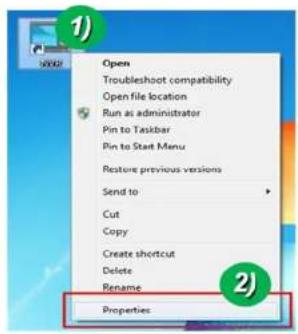
text_image
Open Troubleshoot compatibility Open file location Run as administrator Pin to Taskbar Pin to Start Menu Restore previous versions Send to Cut Copy Create shortcut Delete Rename Properties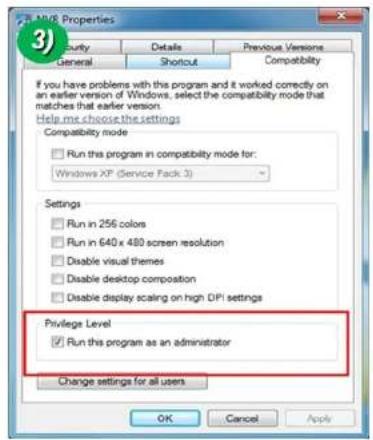
text_image
MUSE Properties Security Details Previous Versions General Shortcut Compatibility If you have problems with this program and it worked correctly on an earlier version of Windows, select the compatibility mode that matches that earlier version. Help me choose the settings Compatibility mode Run this program in compatibility mode for: Windows XP (Service Pack 3) Settings Run in 256 colors Run in 640 x 480 screen resolution Disable visual themes Disable desktop composition Disable display scaling on high DPI settings Privilege Level Run this program as an administrator Change settings for all users OK Cancel Apply1. UAC (User Access Control) configuration
1) Double-click "User Accounts" in control panel
2) Double-click "Change User Account Control setting"
3) Set to "Never notify"
1) ① 设 \* ConnectFond ▶ Unit Accounts ▶ ▶ 16 ▶ Search
2. Privilege Level Control
1) Select "NVR" icon on the desktop
2) Click right mouse button and select "properties"
3) Check "Privilege Level" in "Compatibility" tab

text_image
Open Troubleshoot compatibility Open file location Run as administrator Pin to Taskbar Pin to Start Menu Restore previous versions Send to Cut Copy Create shortcut Delete Rename Properties
text_image
MME Properties Security Details Previous Versions General Shortcut Compatibility If you have problems with this program and it worked correctly on an earlier version of Windows, select the compatibility mode that matches that earlier version. Help me choose the settings Compatibility mode Run this program in compatibility mode for: Windows XP (Service Pack 3) Settings Run in 256 colors Run in 640 x 480 screen resolution Disable visual themes Disable desktop composition Disable display scaling on high DPI settings Privilege Level Run this program as an administrator Change settings for all users OK Cancel Apply5.4. Technical Assistance
If you need any technical assistance, please contact your dealer. For immediate service please provide the following information.

- Model name
- MAC address and Registration number
- Purchase date
- Description of the problem
- Error message
6. Appendix - OSD menu control
To control OSD menu, there are two methods.
First is Video setup page in Administration Tool using Internet Browser as below.

text_image
VIDEO SETUP Channel Selection Channel 1 Video Adjust Contrast 50 Brightness 50 Saturation 50 Hue 50 OSD Time Display Enable Position LEFT-BOTTOM OSD Menu Control SAVE Restore original values CONFIRM SETUPScond is OSD menu controller on camera as below.

text_image
N 8 W T VIDEO TEST SETUP LED LEVEL RESET6-1. OSD
All camera functions are menu driven for easy use.
6-2. Preset Mode

text_image
SPECO TECH ▶ 1.PRESET MODE INDOOR ← 2.MAIN SETUP 3.EXIT RESET ←- Preset: INDOOR / OUTDOOR / LOW LIGHT / HALLWAY / LOBBY / ELEVATOR.
- Used for a quick and easy setup for the installation environment.
6-3. Menu Setup
- Press the Function Setup switch.
- Main setup menu is displayed on the monitor screen.

text_image
MAIN SETUP ► 1.LENS DC ← 3. EXPOSURE ↕- To finish the setting, select 'RETURN' and press the Function Setup switch.
NOTE
■ An item with the ◀ icon also has sub menus. To select a sub menu, select an item with the icon and press the Function Setup switch.
■ An item with the --- icon is unavailable due to function settings.
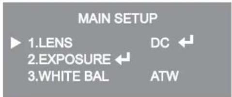
6-4. Lens Setting
Using this function, you can control the screen brightness.
- When the SETUP menu screen is displayed, select 'LENS' by using the Function Setup switch so that the arrow indicates 'LENS'.
- DC: You can adjust the minimum shutter and maximum value of ESC shutter mode.
text_image
MAIN SETUP ► 1.LENS DC ← 2.EXPOSURE ← 3.WHITE BAL ATWNOTE
■ If color rolling occurs when using a DC lens, set Shutter to Fixed (---).
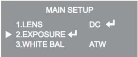
6-5. Exposure Setting
text_image
MAIN SETUP 1.LENS DC 2.EXPOSURE 3.WHITE BAL ATW- When the SETUP menu screen is displayed, select 'EXPOSURE' by using the Function Setup Switch.
- Select a desired mode using the Function Setup switch.

text_image
EXPOSURE SETUP ► 1.BRIGHTNESS 25 2.SHUTTER --- 3.AGC HIGH 4.INTENSIFY OFF 5.RETURN ←ONSIP OB1 Owner's Manual
* LOW : Allows automatic gain control from 5.3dB to 32dB.
* HIGH : Allows automatic gain control from 5.3dB to 37dB.
INTENSIFY: When it is night or dark, the camera automatically detects then light level and maintains a clear picture if this mode is activated.
* OFF : Deactivates the INTENSIFY function.
* AUTO : Activates the INTENSIFY function.
◆ RETURN : Select this to save the changes in the EXPOSURE menu and return to the SETUP menu.
NOTE
If you press the Function Setup switch to 'AUTO' mode, you can adjust brightness by increasing or decreasing the shutter speed. (x2 \~ x512)
Note that the higher the zoom level, the brighter the screen, but the more likely there will be a ghosting effect.
It is normal for Noise, Spots and Whitish symptoms to appear in INTENSIFY mode when the D-ZOOM level is increased.
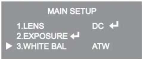
6-6. White Balance (White Bal) Setting
Use the White Balance function to adjust the screen color.
- When the SETUP menu screen is displayed, select 'White Bal' by using the function Setup switch so that the arrow indicates 'White Bal'.
- Select a desired mode using the Function Setup switch.
text_image
MAIN SETUP 1.LENS DC 2.EXPOSURE 3.WHITE BAL ATW* Select one of the following 5 modes, as appropriate for your purpose.
◆ ATW : Select this when the color temperature is between 1,700°K and 11,000°K.
◆ OUTDOOR : Select this when the color temperature is between 1,700°K and 11,000°K. (sodium light inclusion)
INDOOR : Select this when the color temperature is between 4,500°K and 8,500°K.
◆ MANUAL : Select this to fine-tune White Balance manually. Set White Balance first by using the ATW or AWC mode. After that switch to MANUAL mode, fine-tune the White Balance and then press the Function Setup switch.
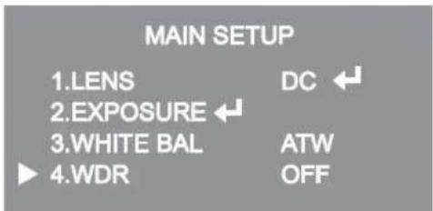
6-7. WDR Setting
WDR illuminates darker spots of an image while retaining the same light level for brighter spots to even out the overall brightness of images with high contrast between bright and dark spots.
text_image
MAIN SETUP 1.LENS DC 2.EXPOSURE 3.WHITE BAL ATW 4.WDR OFF- When the SETUP menu screen is displayed, select 'WDR' by using the switch so that the arrow indicates 'WDR'.
- Use the switch to change the WDR level according to the contrast between bright and dark areas.9
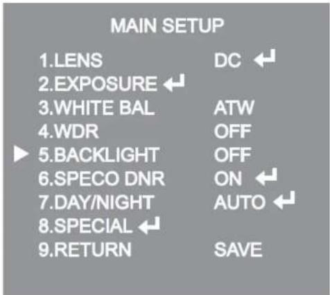
6-8. Backlight Setting
Unlike conventional cameras, the 650Line Intensifier3™ Series are designed to deliver a distinctive subject and background at the same time, even when the subject is backlight, by using the features of the proprietary W-V DSP chip.
- When the SETUP menu screen is displayed, select 'BACKLIGHT' by using the Function Setup switch so that the arrow indicates 'BACKLIGHT'.
text_image
MAIN SETUP 1.LENS DC ← 2.EXPOSURE ← 3.WHITE BAL ATW 4.WDR OFF 5.BACKLIGHT OFF 6.SPECO DNR ON ← 7.DAY/NIGHT AUTO ← 8.SPECIAL ← 9.RETURN SAVEBLC SETUP
LEVEL LOW
TOP 38
BOTTOM 109
LEFT 54
RIGHT 121
Press Set to Return
BLC SETUP
LEVEL LOW
TOP 38
BOTTOM 109
LEFT 54
RIGHT 121
Press Set to Return
NOTE
Because there can be a difference in the effectiveness of HLC according to the amount of light area in the screen, optimize the installation angle for the best HLC performance.
■ When dark, the HLC is only activated when a bright light exceeding a specific size in NIGHT ONLY mode.
■ The HLC is not activated in day light or when bright light is not present at night in NIGHT ONLY mode.
■ BLC Function doesn't work in the B/W mode of the DAY/NIGHT menu.
6-9. SPECO DNR Setting
This function reduces the background noise in a low luminance environment.
- When the SETUP menu screen is displayed, select 'SPECO DNR' by using the Function Setup switch so that the arrow indicates 'SPECO DNR'.

text_image
MAIN SETUP 1.LENS DC ← 2.EXPOSURE ← 3.WHITE BAL ATW 4.WDR OFF 5.BACKLIGHT OFF 6.SPECO DNR ON ← 7.DAY/NIGHT AUTO ← 8.SPECIAL ← 9.RETURN SAVE- Select a desired mode using the Function Setup switch.
◆ OFF : Deactivates SPECO DNR. Noise is not reduced.
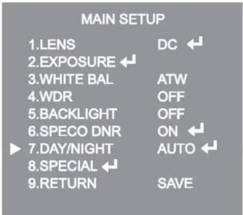
6-10. Day/Night Setting
You can display pictures in color or black and white.
- When the SETUP menu screen is displayed, select 'DAY:NIGHT' by using the Function Setup switch so that the arrow indicates 'DAY:NIGHT'.
text_image
MAIN SETUP 1.LENS DC 2.EXPOSURE 3.WHITE BAL ATW 4.WDR OFF 5.BACKLIGHT OFF 6.SPECO DNR ON 7.DAY/NIGHT AUTO 8.SPECIAL 9.RETURN SAVE- Select a desired mode using the Function Setup Switch according to the picture display you want.
◆ COLOR : The picture is always displayed in color.

text_image
AUTO SETUP ▶ 1.BURST MODE ON 2.COLOR→B/W DURATION FAST DWELL TIME 3SEC 3.B/W→COLOR DURATION FAST DWELL TIME 10SEC 4.RETURN ←- BURST MODE : You can turn on or off the burst signal on B/W mode.
- DURATION : You can select brightness of illumination about changing the day/night mode.
- DWELLTIME : You can select the duration time about changing the day/night mode.
→3s, 5s, 7s, 10s, 15s, 20s, 30s, 40, 60s
| COLOR→B/W | B/W→COLOR | |
| FAST | 2.5 lux | 5 lux |
6-11. Special Setting
- When the SETUP menu screen is displayed, select 'SPECIAL' by using the Function Setup switch so that the arrow indicates 'SPECIAL'.
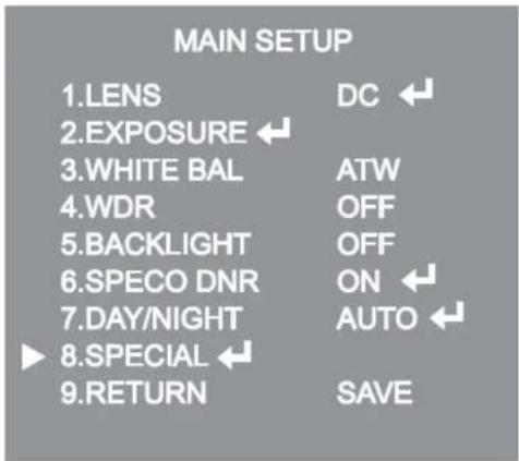
text_image
MAIN SETUP 1.LENS DC ← 2.EXPOSURE ← 3.WHITE BAL ATW 4.WDR OFF 5.BACKLIGHT OFF 6.SPECO DNR ON ← 7.DAY/NIGHT AUTO ← 8.SPECIAL ← 9.RETURN SAVE- Select a desired mode using the Function Setup switch.

◆ IMAGE ADJ. :
1) When the SETUP menu screen is displayed, select 'IMAGE ADJ' by using the Function Setup switch so that the arrow indicates 'IMAGE ADJ'.
2) Select a desired mode using the Function Setup switch.

text_image
IMAGE SETUP ► 1.V-REV 2.H-REV OFF 3.D-ZOOM OFF 4.DIS 5.FONT COLOR WHITE 6.SHARPNESS ON ← 7.RETURN ←* V-REV : You can flip the picture vertically on the screen.
* H-REV : You can flip the picture horizontally on the screen.
* D-ZOOM: You can use a digital zoom of x1 \~ x16.
* DIS (Digital Image Stabilizer): This function mitigates any picture movement due to external factors such as wind.
◆ CAM TITLE: If you enter a title, the title will appear on the monitor.
CAMERA TITLE SETUP
ABCDEFGHIJKLMNOPQRSTUVWXYZ
NOPQRSTUVWXYZ
abcdefghijklmnopqrstuvwxyzghijklm
nopqrstuvwxyz
-.0123456789
←→CLR POS END
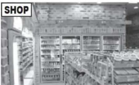
natural_image
Interior view of a supermarket refrigerated section with shelves and refrigerators (no visible text or signage)NOTE
■ When the CAM TITLE menu is 'OFF', no title will be displayed on the monitor screen even if you enter one.
■ Only English is available in this mode.
If you move the cursor to CLR and press the Function Setup switch, all the letters are deleted. To edit a letter, change the cursor to the bottom left arrow and press the Function Setup switch. Move the cursor over the letter to be edited, move the cursor to the letter to be inserted and then press the Function Setup switch.
SYNC: In areas where the supply is at 60Hz(NTSC), 50Hz(PAL), you can synchronize the output phase of multiple cameras using the power synchronization function (Line-Lock) without using a synchronization signal generator.
- INT: Internal Synchronization Type
- L/L: Power Synchronization Type, Line-lock
* Press the Function Setup switch.
* You can select a desired phase from 0 to 359 when select 'phase'.
NOTE
■ When using AC power at 60Hz(NTSC), 50Hz(PAL), frequency, you can use the L/L type synchronization.
■ When the power is DC 12V, the SYNC menu is fixed to the 'INT' mode.
♦ MOTION DET: This product has a feature that allows you to observe movement of objects in 8 different areas on the screen, and the words 'MOTION DETECTED' appear on the screen when movement is detected. Activity can be monitor more efficiently.
ONSIP OB1 Owner's Manual
indicates 'MOTION DET'.
2) Set up the mode using the Function Setup switch.
- SENSITIVITY: You can select up to 8 MD areas. When SENSITIVITY number is high, motion detection sensitivity is increased to recognize even small movement.
- AREA MODE: Determines whether to use the MD area selected in SENSITIVITY.
- SEL POS: Determines which of the 4 vertices of each MD area is to be used.
- XPOS: Determines the coordinate of the horizontal axis for SEL POS.
- YPOS: Determines the coordinate of the vertical axis for SEL POS.
- FILL→SET: Fills in a selected MD area. The color of the area can be selected from brown, orange, blue, cyan, green, yellow, magenta and red.
- RETURN: Select this to save the MOTION DET menu settings and return to the SPECIAL menu.
◆ PRIVACY: Mask an area you want to hide on the screen.
| PRIVACY AREA SETUP | |
| 1.AREA | AREA1 |
| 2.MODE | OFF |
| 3.MASK COLOR | GREEN |
| 4.MASK TONE | 1 |
| 5.TOP | 39 |
| 6.BOTTOM | 79 |
| 7.LEFT | 12 |
6-12. RETURN Setting
Select a desired RETURN mode using the Function Setup Switch.
- SAVE: Save the current settings and RETURN the MAIN SETUP menu.
- NOT SAVE: Do not save the current settings and RETURN the MAIN SETUP menu.
- RESET: Resets the camera settings to the factory defaults. Language, Communication and Monitor Settings are not initialized.