ZIPL4D1 - Security Camera Speco Technologies - Free user manual and instructions
Find the device manual for free ZIPL4D1 Speco Technologies in PDF.

User questions about ZIPL4D1 Speco Technologies
0 question about this device. Answer the ones you know or ask your own.
Ask a new question about this device
Download the instructions for your Security Camera in PDF format for free! Find your manual ZIPL4D1 - Speco Technologies and take your electronic device back in hand. On this page are published all the documents necessary for the use of your device. ZIPL4D1 by Speco Technologies.
USER MANUAL ZIPL4D1 Speco Technologies
text_image
speco technologies®User Guide (Ver. 1.3)
Models: N4/8NSL
4/8 Channel Network Video Recorder
Cautions

text_image
CAUTION RISK OF ELECTRIC SHOCK DO NOT OPEN CAUTION: TO REDUCE THE RISK OF ELECTRIC SHOCK, DO NOT REMOVE COVER (OR BACK). NO USER SERVICEABLE PARTS INSIDE. REFER SERVICING TO QUALIFIED SERVICE PERSONNEL.Explanation of Graphical Symbols

This symbol indicates the presence of important operang and maintenance (servicing) instrucons in the literature accompanying the product.

This symbol indicates the presence of "dangerous voltage" within the product's enclosure that may be of sucient magnitude to constute a risk of electric shock, property damage, personal injury, or death.
These precautions must be followed for safety reasons

Warning
- Do not use if the unit emits smoke.
- Do not disassemble the unit.
- Do not place any heavy or sharp objects on the unit.
- Do not place on uneven surface.
- Do not expose to shock or vibration.
- Do not move the unit when the unit is powered on.
- Do not block, and allow dust to accumulate in the air vents.
- Do not restrict airflow of the unit; doing so can damage the unit.
- Only qualified and experienced personnel should perform installation and servicing.
- Turn off the power of the NSL when connecting Cameras, Audio Cables.
- The manufacturer is not responsible for any damage caused by improper use of the product or failure to follow instructions for the product.
- The manufacturer is not responsible for any problems caused by or resulting from the user physically opening the NSL for examination or attempting to repair the unit.
- For NSL models with the PoE Switch, it is strongly recommended that the 48V
Product Components
Please make sure the following components are included as specified below.
| Desktop:N4NSL / N8NSL | 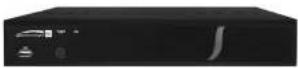 |
| Remote Control | 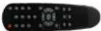 |
| Battery 1.5V (AAA x 2 EA) |  |
| Quick Setup Guide &User Guide |  |
| Mouse for NSL |  |
| Software & Manual CD |  |
| Power Adaptor(DC48V for POE)& Power cable (110V or 220V) | 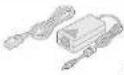 N4NSL : 1.2A, N8NSL : 2A N4NSL : 1.2A, N8NSL : 2A |
Specifications for NSL
| MODEL NAME | N4NSL | N8NSL | ||
| Description | 4ch NVR with 4-PoE | 8ch NVR with 8-PoE | ||
| Video | Input | IP Camera (Throughput) | 4 | 8 |
| Normal Resolution | Max. 1920x1080 | |||
| Highest Resolution | Not Support | |||
| Output | Main Monitor | VGA and HDMI (Max. 1920x1080) | ||
| Sub Monitor | None | |||
| Audio | Input | IP Camera (Network) | 4 | 8 |
| Local Input (RCA) | None | None | ||
| Output | Local Output (RCA) | 1 | 1 | |
| Audio Codec | G.711 | |||
| Event | SensorIn | IP Camera (Network) | 4 | 8 |
| Local Input (Terminal Block) | None | None | ||
| Local Alarm Output (Terminal Block) | None | None | ||
| Motion Detection (from IP Camera) | Yes | |||
| Serial | RS-232C | None | None | |
| RS-485 | None | None | ||
| Network | Private (IP Camera, Auto Connection) | 802.3af x 4 | 802.3af x 8 | |
| LAN (IP Camera, Remote Access) | 10/100 Base-TX | 10/100/1000 Base-TX | ||
| Protocols | TCP/IP, UDP, DHCP, HTTP, NTP, SMTP, RTP, RTSP, ONVIF | |||
| Streaming | Relay of the IP Camera's Sub-stream | |||
| USB | Front | 1 | 1 | |
| Rear | 1 | 1 | ||
| User I/F | Input Method | IR, Mouse | ||
| Features | Dynamic DNS | Yes (Free DDNS) | ||
| Digital Zoom | Yes | |||
| DLS (Day Light Saving) | Yes | |||
| NTP (Network Time Protocol) | Yes | |||
| S.M.A.R.T | Yes | |||
| Internal Beep | Yes | |||
| Multi-Language | Yes | |||
| e-mail Notification | Yes | |||
| Network Access | 3G Mobile | iPad / iPhone / Android | ||
| Web Viewer | Windows (IE, Chrome, Firefox, Safari) | |||
| PC Client | Single / Multi Client and CMS (64 channels) | |||
| Remote Setup and Upgrade | Yes | |||
| Power | Power Supply Voltage | DC 48V 1.2A (57.6Watt) | DC 48V 2.0A(96Watt) | |
| Temperature | Operation | 41° F ~ 104° F (5°C ~ 40°C) | ||
| Storage | 14° F ~ 122° F (-10°C ~ 50°C) | |||
| Humidity | Operation | 20% ~ 80% (Non-condensing) | ||
| Dimension | Unit Dimension (W x H x D) | 11.8' x 8.9' x 2.0' (300mm x 227mm x 53mm) | ||
Please note that specifications and unit exterior design are subject to change without notification.
Table of Contents
- Main Features 10
- Initial Boot-up Process....11
2-1. Initial Boot up and Basic Time Setup.... 11
2-2. Setting up Daylight Savings Time....12
2-3. Setting NTP (Network Time Protocol)....12
2-4.EZ SETUP 15
2-5. PoE Port SETUP....16
2-6. IP Camera SETUP (through Web Viewer page) 19
2-7. Dual Streaming....19
- Front and Rear Panels 20
3-1. Desktop Front Panel 20
3-2. Connectors 20
3-3. Remote Control....21
- Setting up the NSL 22
4-0. Setup – Main Live Screen 22
4-1. Setup – IP CAMERA....23
4-1-1. SCAN Menu....25
4-1-2. ONVIF SETUP Menu 26
4-2. Setup – SYSTEM....28
4-3. Setup – RECORD Mode .... 31
4-3-1. Recording Schedules....33
4-4. Setup - DEVICE Mode ....34
4-4-1. Digital Deterrent....35
4-4-2. Motion Zone Setup....36
5-3-3. Event Search .... 51
5-3-4. Go To First Time....52
5-3-5. Go To Last Time....52
5-3-6. Go To Specific Time 52
5-3-7. Archive List .... 52
5-3-8. Log List....53
5-4. Play Mode....53
- Back Up....55
6-1. Still Image Backup onto USB Flash Drive....55
6-2. Video Backup onto USB Flash Drive during playback 55
6-2. EZCopy: Video Backup onto USB Flash Drive during playback....57
6-3. Transferring Still Images or Video from the ARCHIVE List....58
6-4. Playback of Backup Video....59
6-5-1. AVI Format....59
6-5-2. NSF Format .... 59
- Network Access Using the Multi-Sites Network Viewer 60
7-1. Overview....60
7-2. PC Requirements....60
7-3. Installation of the Program 61
7-4. Live Window....62
7-4-1.Main User Interface....62
7-4-2. Control Buttons....62
7-5. Search and Playback Window....63
7-5-1. Main User Interface....63
7-5-2. Main Control Panel 64
7-6. Setup of SpecoTech Multi Client....65
7-7-9. Remote Upgrade....77
7-7-10. Information....77
7-8. Operation....78
7-8-1. Addition, Delete, and Modify of NSL Sites 78
7-8-2. Connect and Disconnect....79
7-8-3. Still-image Capture During Live....80
7-8-4. Recording Video on Local PC During Live 81
7-8-5. Local Playback and Remote Playback 82
7-8-6. AVI Backup during Playback 84
-
Network Access Using the Web-Browser Viewer 86
-
Network Access Using the Smart Phone Viewer 88
9-1. App Viewer for iPhone....88
9-1-1. Live....88
9-1-2.PTZ Control 90
9-1-3. Playback....90
9-2. App Viewer for Android Phone....91
9-2-1. Live....91
9-2-2. Playback....92
9-2-3.PTZ Control 93
APPENDIX: Network Connection - LAN 93
APPENDIX: Network Connection – Internet and DDNS 96
1. Main Features
■ Automatic IP Camera Detection and connection (Plug & Play)
■ Easy Record, Copy and Setup
■ Easy Search by Thumbnail Preview
■ Easy Copy
■ Easy Network
■ Easy IP Camera Setup
NOTE: Under federal law, The Fourth Amendment to the U.S. Constitution, Title III of the Omnibus Crime Control and Safe Streets Act of 1968, as amended by the Electronic Communications Privacy Act of 1986 (18 U.S.C. § 2510, et seq.), and the Foreign Intelligence Surveillance Act of 1978 (50 U.S.C. 1801; et seq.) permit government agents, acting with the consent of a party to a communication, to engage in warrantless interceptions of telephone communications, as well as oral and electronic communications.
■ Covert camera operation provides enhanced security and administrator control
■ Dynamically programmable recording priority, motion detection, alarms and scheduling
■ Simple and Easy Graphic User Interface
■ Simple Scheduler
■ HDMI Output
■ VGA Output
■ Password to secure installation authorization
■ Network software supports 10/100Mbps
■ USB 2.0 port for video clip exporting and easy firmware upgrade via USB Flash Drive
2. Initial Boot-up Process
2-1. Initial Boot up and Basic Time Setup
- During the first boot up, the following logo will be displayed.

text_image
speco technologies- After the logo, select the language and set date and time as specified below.

text_image
CHOOSE LANGUAGE ENGLISH < PREV NEXT > CLOSE
text_image
Initializing system It may take a few seconds or minutes to check the system 90% Initialize Network...Done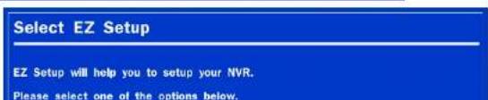
text_image
Select EZ Setup EZ Setup will help you to setup your NVR. Please select one of the options below.2-2. Setting up Daylight Savings Time
To enable Daylight Saving feature/NTP synchronization, take the following steps.
- Enter the SETUP mode. The default Username is "ADMIN" and Password is "1111".
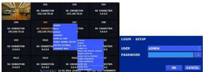
text_image
CH2 NO CONNECTION 192.168.78.18 CH3 NO CONNECTION 192.168.78.18 CH4 NO CONNECTION 0.0.0 CH5 NO CONNECTION 192.168.78.18 CH6 NO CONNECTION 0.0.0 CH7 NO CONNECTION 192.168.78.18 CH8 NO CONNECTION 0.0.0 CH9 NO CONNECTION 0.0.0 CH10 NO CONNECTION 0.0.0 CH11 NO CONNECTION 0.0.0 CH12 NO CONNECTION 0.0.0 CH13 NO CONNECTION 0.0.0 CH14 NO CONNECTION 0.0.0 CH15 NO CONNECTION 0.0.0 CH16 NO CONNECTION 0.0.0 CH17 NO CONNECTION 0.0.0 CH18 NO CONNECTION 0.0.0 CH19 NO CONNECTION 0.0.0 CH20 NO CONNECTION 0.0.0 CH21 NO CONNECTION 0.0.0 CH22 NO CONNECTION 0.0.0 CH23 NO CONNECTION 0.0.0 CH24 NO CONNECTION 0.0.0 CH25 NO CONNECTION 0.0.0 CH26 NO CONNECTION 0.0.0 CH27 NO CONNECTION 0.0.0 CH28 NO CONNECTION 0.0.0 CH29 NO CONNECTION 0.0.0 CH30 NO CONNECTION 0.0.0 CH31 NO CONNECTION 0.0.0 CH32 NO CONNECTION 0.0.0 CH33 NO CONNECTION 0.0.0 CH34 NO CONNECTION 0.0.0 CH35 NO CONNECTION 0.0.0 CH36 NO CONNECTION 0.0.0 CH37 NO CONNECTION 0.0.0 CH38 NO CONNECTION 0.0.0 CH39 NO CONNECTION 0.0.0 CH40 NO CONNECTION 0.0.0 CH41 NO CONNECTION 0.0.0 CH42 NO CONNECTION 0.0.0 CH43 NO CONNECTION 0.0.0 CH44 NO CONNECTION 0.0.0 CH45 NO CONNECTION 0.0.0 CH46 NO CONNECTION 0.0.0 CH47 NO CONNECTION 0.0.0 CH48 NO CONNECTION 0.0.0 CH49 NO CONNECTION 0.0.0 CH50 NO CONNECTION 0.0.0- Go to SETUP > SYSTEM > DATE & TIME SETUP
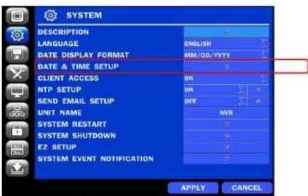
text_image
SYSTEM DESCRIPTION LANGUAGE DATE DISPLAY FORMAT DATE & TIME SETUP CLIENT ACCESS NTP SETUP SEND EMAIL SETUP UNIT NAME SYSTEM RESTART SYSTEM SHUTDOWN EZ SETUP SYSTEM EVENT NOTIFICATION ENGLISH MM/DD/YYYY ON OK OFF MYR APPLY CANCEL- Select ON from the DAYLIGHT SAVING dropdown menu.

- Select the proper TIME ZONE time.
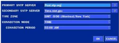
text_image
PRIMARY SNTP SERVER Poul.ntp.org SECONDARY SNTP SERVER Time.nist.gov TIME ZONE GMT -5:00 (Montreal/New York) CONNECTION MODE TIME CONNECTION PERIOD 03:00 AM OK CANCELTable2.3.1. GMT Time Zone
| State | Standard Time | Daylight-Saving Time | |
| AL | Alabama | GMT-6 | GMT-5 |
| AK | Alaska | GMT-9 | GMT-8 |
| AK | Alaska (Aleutian Islands) | GMT-10 | NA |
| AZ | Arizona | GMT-7 | NA |
| AZ | Arizona (Navajo) | GMT-7 | GMT-6 |
| AR | Arkansas | GMT-6 | GMT-5 |
| CA | California | GMT-8 | GMT-7 |
| CO | Colorado | GMT-7 | GMT-6 |
| CT | Connecticut | GMT-5 | GMT-4 |
| DC | District of Columbia | GMT-5 | GMT-4 |
| DE | Delaware | GMT-5 | GMT-4 |
| FL | Florida | GMT-5 | GMT-4 |
| FL | Florida (W) | GMT-6 | GMT-5 |
| GA | Georgia | GMT-5 | GMT-4 |
| HI | Hawaii | GMT-10 | NA |
| MI | Michigan (W) | GMT-6 | GMT-5 |
| MN | Minnesota | GMT-6 | GMT-5 |
| MS | Mississippi | GMT-6 | GMT-5 |
| MO | Missouri | GMT-6 | GMT-5 |
| MT | Montana | GMT-7 | GMT-6 |
| NE | Nebraska | GMT-6 | GMT-5 |
| NE | Nebraska (W) | GMT-7 | GMT-6 |
| NV | Nevada | GMT-8 | GMT-7 |
| NH | New Hampshire | GMT-5 | GMT-4 |
| NJ | New Jersey | GMT-5 | GMT-4 |
| NM | New Mexico | GMT-7 | GMT-6 |
| NY | New York | GMT-5 | GMT-4 |
| NC | North Carolina | GMT-5 | GMT-4 |
| ND | North Dakota | GMT-6 | GMT-5 |
| ND | North Dakota (W) | GMT-7 | GMT-6 |
| OH | Ohio | GMT-5 | GMT-4 |
| OK | Oklahoma | GMT-6 | GMT-5 |
| OR | Oregon | GMT-8 | GMT-7 |
| OR | Oregon (E) | GMT-7 | GMT-6 |
| PA | Pennsylvania | GMT-5 | GMT-4 |
| RI | Rhode Island | GMT-5 | GMT-4 |
| SC | South Carolina | GMT-5 | GMT-4 |
| SD | South Dakota (E) | GMT-6 | GMT-5 |
| SD | South Dakota (W) | GMT-7 | GMT-6 |
| TN | Tennessee (E) | GMT-5 | GMT-4 |
2-4. EZ SETUP
Quick installation Menu for NSL and IP Camera Easy installation(Right-Click on the Main Screen)
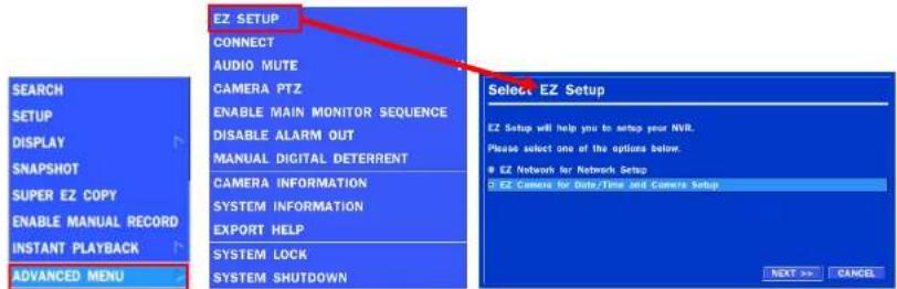
text_image
EIZ SETUP CONNECT AUDIO MUTE CAMERA PTZ ENABLE MAIN MONITOR SEQUENCE DISABLE ALARM OUT MANUAL DIGITAL DETERRENT CAMERA INFORMATION SYSTEM INFORMATION EXPORT HELP SYSTEM LOCK SYSTEM SHUTDOWN Select EZ Setup EZ Setup will help you to setup your NVR. Please select one of the options below. EZ Network for Network Setup EZ Camera for Date/Time And Camera Setup NEXT >> CANCEL SEARCH SETUP DISPLAY SNAPSHOT SUPER EZ COPY ENABLE MANUAL RECORD INSTANT PLAYBACK ADVANCED MENUFigure 2.4. EZ Setup Screen
2.4.1. Setup DATE & TIME, IP CAMERA configurations.
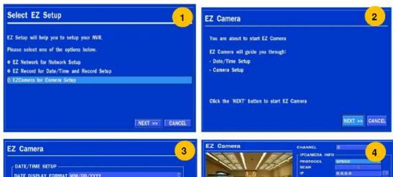
text_image
Select EZ Setup EZ Setup will help you to setup your NVR. Please select one of the options below. • EZ Network for Network Setup • EZ Record for Date/Time and Record Setup • EZCamera for Camera Setup NEXT >> EZ Camera You are about to start EZ Camera EZ Camera will guide you through: - Date/Time Setup - Camera Setup Click the 'NEXT' button to start EZ Camera NEXT >> EZ Camera DATE/TIME SETUP DATE DISPLAY FORMAT MM/DD/YYYY CHANNEL IPCAMERA INFO PHOTOCOL SCAN 0.0.0.0 42.4.2. EZ NETWORK
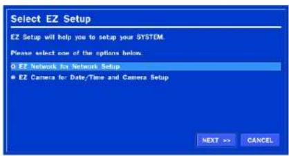
text_image
Select EZ Setup EZ Setup will help you to setup your SYSTEM. Please select one of the options below. ● EZ Network for Network Setup ● EZ Camera for Date/Time and Camera Setup NEXT >> CANCEL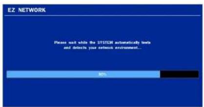
text_image
EZ NETWORK Please wait while the SYSTEM automatically beds and disconnect your extensive environment... BRL
text_image
EZ NETWORK You have now completed your network setup. You can now enter the ddms host name into Speco-Player app, Web browser, and SecureGuard. DDMS host name n16nsf_091727.ddms.specoddns.net Click 'EDIT' to edit the host name. Click 'FINISH' to complete EZ Network. EDIT FROM CANCEL
text_image
HOST NAME n16nsf_speco · 1 2 3 4 5 6 7 8 9 0 · = — q w e r t y u i o p [ ] CAPS a s d f g h j k l : SHIFT z x c v b n m . / SHIFT CLEAR SPACE CLOSE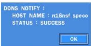
text_image
DDNS NOTIFY : HOST NAME : n16nsf_speco STATUS : SUCCESS OKFigure 2.4.2. EZ NETWORK Setup Procedure
2.5.1 Connecting the Camera
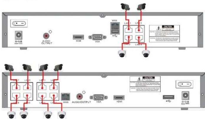
text_image
AUDIO OUTPUT HDMI VGA LAN 1 LAN 2 LAN 3 LAN 4 LAN 5 LAN 6 LAN 7 LAN 8 LAN 9 LAN 10 WAN AUDIO OUTPUT VGA HDMI LAN 10 LAN 11 LAN 12 LAN 13 LAN 14 LAN 15 LAN 16 LAN 17 LAN 18 LAN 19 LAN 20 LAN 21 LAN 22 LAN 23 LAN 24 LAN 25 LAN 26 LAN 27 LAN 28 LAN 29 LAN 30 LAN 31 LAN 32 LAN 33 LAN 34 LAN 35 LAN 36 LAN 37 LAN 38 LAN 39 LAN 40 LAN 41 LAN 42 LAN 43 LAN 44 LAN 45 LAN 46 LAN 47 LAN 48 LAN 49 LAN 50 LAN 51 LAN 52 LAN 53 LAN 54 LAN 55 LAN 56 LAN 57 LAN 58 LAN 59 LAN 60 LAN 61 LAN 62 LAN 63 LAN 64 LAN 65 LAN 66 LAN 67 LAN 68 LAN 69 LAN 70 LAN 71 LAN 72 LAN 73 LAN 74 LAN 75 LAN 76 LAN 77 LAN 78 LAN 79 LAN 80 LAN 81 LAN 82 LAN 83 LAN 84 LAN 85 LAN 86 LAN 87 LAN 88 LAN 89 LAN 90 LAN 91 LAN 92 LAN 93 LAN 94 LAN 95 LAN 96 LAN 97 LAN 98 LAN 99 LAN 100Figure 2.5.1.1 IP Camera Connection Diagram (N4NSL, N8NSL)

text_image
Private Network - IP Cameras only Clients' WAN IP Camerasable 2.5.1. Factory Default of the IP Camera
The following IP Camera settings are recommended for optimal connection with the NSL Series
| Setup Items | Default | Description |
| Network Type | DHCP | The IP Camera must act as a DHCP client for the “Plug and Play”. |
| Encoding Type | CBR | The “CBR” is recommended because of the internal buffer design of the NSL Series |
| Resolution | 1280x720 | The maximum performance of the N8NSL is 1080p@240fps or 720p@240fps.To get higher frame rates per channel, 1280x720 is the recommended resolution. |
| Frame Rate | 25fps | The maximum performance of the N8NSL is 720p@240fps.Therefore 30fps per channel is recommended. (30fps x 8 = 240fps) |
| Bit Rate | 2Mbps | The maximum throughput of the N8NSL is 40Mbps.Therefore 2Mbps per channel is recommended. (4Mbps x 8 = 32Mbps) |
| Sub Stream | CIF512Kbps | For “Dual Streaming”, the sub stream should be turned on.And for the proper streaming through the WAN connection,CIF@512Kbps or lower bitrates per channel is recommended. |
• The NSL Series features a "Plug and Play" function with a PoE Switch.
- The "Plug and Play" functionality requires the IP Camera to be in DHCP mode.
• The NSL automatically assigns an IP Address to the IP Camera. (10.20.30.11 \~ 10.20.30.254)
- The NSL models will automatically map the camera on the PoE Port to the corresponding NVR channel number.
• The NSL PoE Port maximum power consumption
- [N4NSL - 57.6Watt, N8NSL-96Watt]


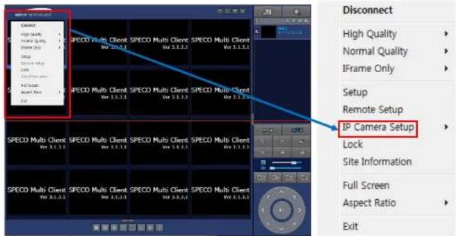
2-6. IP Camera SETUP (through Web Viewer page)
NSL Series allow remote access to the IP Cameras through an "IP Camera Setup" menu.
The PC Web Client features the "IP Camera Setup" menu that can be accessed remotely.
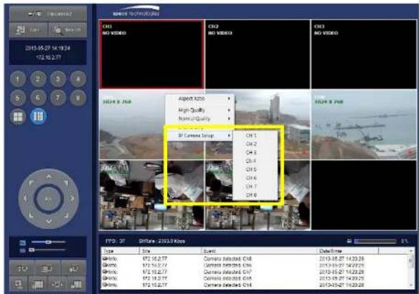
text_image
2015-05-27 14:19:24 172.16.2.77 CRL NO VIDEO CRL2 NO VIDEO CRL3 NO VIDEO Aspect 200 High Quality Normal Quality 3D Camera Setup OH 1 OH 2 OH 3 OH 4 OH 5 OH 6 OH 7 OH 8 FPD: 37 Offense: 2003.0 Kbps Type Size Event: Date/Time Gh/Nx: 172.16.2.77 Camera installed OH 2015-05-27 14:29:25 Gh/Nx: 172.16.2.77 Camera installed OH 2015-05-27 14:29:25 Gh/Nx: 172.16.2.77 Camera installed OH 2015-05-27 14:29:25 Gh/Nx: 172.16.2.77① Click the mouse right button
② Select "IP Camera Setup".
③ Select Channel Number.
④ It launches the camera's web setup page.
In order for the web pages to launch from the "IP Camera Setup" menu when accessed from the WAN, Ports 59011 to 59254 on the router must be port forwarded to the NVR. The local address of the NVR can be found in the system
3. Front and Rear Panels
3-1. Desktop Front Panel

natural_image
Front view of a black electronic device with ports and indicator lights (no visible text or symbols)Figure 3.1.1. Desktop NSL Front panel
Table 3.1.1. Front LED and Port of NSL
| Name | Description |
| POWER | LED light is on when power is applied to the system. |
| HDD | LED light is on when the system is recording video data. |
| USB Port | This USB port for archiving footage into a USB device. (USB 2.0) |
3-2. Connectors

- Do not power this system on before all the connections are completed.
- Make sure all the connections are properly secured. Faulty connection may result in the system being damaged.
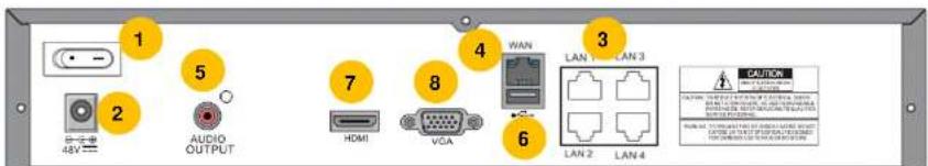
text_image
1 2 AUDIO OUTPUT 5 7 8 VCA 4 WAN 3 LAN 1 LAN 3 6 LAN 2 LAN 4 CAUTION⑦ HDMI OUT: HDMI output port, Connector to the HDMI Monitor, (1280x720, and 1920x1080).
⑧ VGA OUT: Connector for VGA Monitor, Main Video Output.
3-3. Remote Control

text_image
Top-down view of a remote control with numbered labels pointing to key buttons and function keys.Figure 2.3.1. Remote Controller Button
① ID: To set the remote control ID.
② REC: To start and stop manual recording
③ SEARCH: To go to SEARCH menu.
④ F/ADV:
- During playback – To move the playback position 60 seconds forward
- During Pause – To move the playback position moves 1 frame forward
(5) FIREW
4. Setting up the NSL
The following sections detail the initial setup of the NSL.

Menu screen will close if user input is not received within 5 minutes.
4-0. Setup - Main Live Screen
To enter the setup menu, right click on the mouse and select setup from the submenu or press the setup button on the remote control.
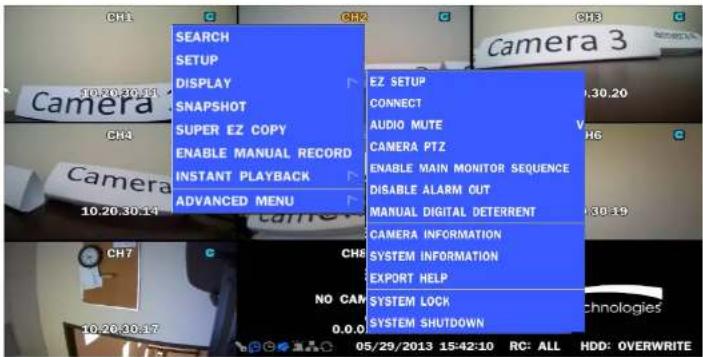
text_image
SEARCH SETUP DISPLAY SNAPSHOT SUPER EZ COPY ENABLE MANUAL RECORD INSTANT PLAYBACK ADVANCED MENU EZ SETUP CONNECT AUDIO MUTE CAMERA PTZ ENABLE MAIN MONITOR SEQUENCE DISABLE ALARM OUT MANUAL DIGITAL DETERRENT CAMERA INFORMATION SYSTEM INFORMATION EXPORT HELP SYSTEM LOCK SYSTEM SHUTDOWN 05/29/2013 15:42:10 RC: ALL HDD: OVERWRITETable 4.0.1. Live Screen and Quick Operation Window

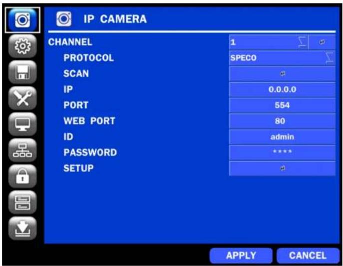
4-1. Setup - IP CAMERA
Press the SETUP button and enter the password. The IP Camera setup menu is displayed below.
text_image
IP CAMERA CHANNEL 1 PROTOCOL SPEC0 SCAN IP 0.0.0.0 PORT 554 WEB PORT 80 ID admin PASSWORD **** SETUP APPLY CANCELFigure 4.1.1. IP Camera mode setup screen
Table 4.1.1. Menu items in IP CAMERA mode setup
| Item | Description |
| CHANNEL |
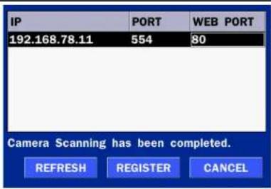
text_image
IP PORT WEB PORT 192.168.78.11 554 80 Camera Scanning has been completed. REFRESH REGISTER CANCELIP: Enter the address of IP camera to connect, or select from scanned list.
PORT: Enter the port number of IP camera to connect
WEB PORT: Enter the web port number of IP camera to connect
OTHERS: Change the IP camera setting. Double click the empty box and then Log-In box will be pop-up. (Enter ID and PASSWORD of IP Camera)

text_image
ID admin PASSWORD **** OKPROTOCOL Select the protocol for the IP Camera.
SCAN Automatic IP Camera search on the local network.
IP Set up IP camera address.
PORT Set up the RTSP port of the IP Camera (default: 554)
WEB PORT Set up the web port of IP Camera (default: 80)
ID Enter ID of IP CAM
4-1-1. SCAN Menu
Scan for IP Cameras on network using ONVIF/SPECO protocols.protocols
text_image
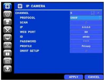
IP CAMERA CHANNEL PROTOCOL SCAN IP WEB PORT ID PASSWORD PROFILE ONVIF SETUP 0 ONVIF - 0.0.0.0 80 admin **** Primary + APPLY CANCEL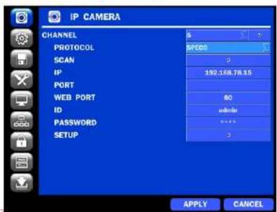
text_image
IP CAMERA CHANNEL PROTOCOL SCAN IP PORT WEB PORT ID PASSWORD SETUP SPODS 2 192.168.78.15 80 admin 3 APPLY CANCELFigure 4.1.2 IP CAMERA Setup Screen
text_image
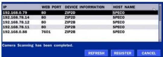
IP 192.168.0.79 80 ZIP2D SPECO 192.168.78.14 80 ZIP2D SPECO 192.168.78.12 80 ZIP2B SPECO 192.168.78.11 80 ZIP2B SPECO 192.168.0.88 7601 ZIP2B SPECO Camera Scanning has been completed. REFRESH REGISTER CANCEL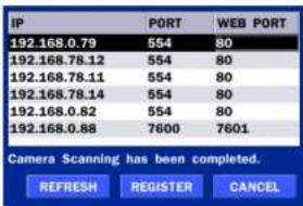
text_image
IP 192.168.0.79 554 80 192.168.78.12 554 80 192.168.78.11 554 80 192.168.78.14 554 80 192.168.0.82 554 80 192.168.0.88 7600 7601 Camera Scanning has been completed. REFRESH REGISTER CANCELFigure 4.1.3 Left Image using ONVIF Protocol SCAN, Right Image using SPECO Protocol SCAN
| PROFILE NAME RESOLUTION | FRAME RATE | BIT RATE | I-FRAME INTERVAL | H264 PROFILE | |
| Profile0 | 1920 X 1080 | 30 | 2500 | 30 | Main |
| Profile1 | 640 X 360 | 30 | 1024 | 30 | Main |
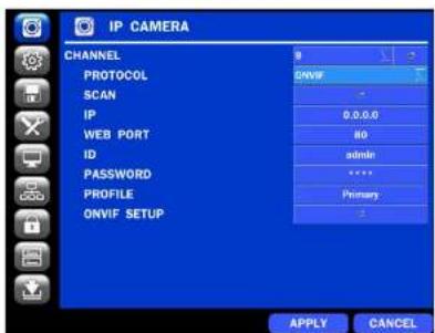
4-1-2. ONVIF SETUP Menu
text_image
IP CAMERA CHANNEL PROTOCOL SCAN IP WEB PORT ID PASSWORD PROFILE ONVIF SETUP 0 ONVIF 0.0.0.0 80 admin **** Primary 0 APPLY CANCELFigure 4.1.2 IP CAMERA Setup Screen (ONVIF)
The NSL Series can search for IP Cameras that are conformant to ONVIF (Open Network Video Interface Forum).
In order to search for ONVIF Cameras, the field associated with VENDOR has to be set to ONVIF.
Click on the Box associated with SCAN to scan the networks for ONVIF Conformance cameras.

text_image
IP 192.168.56.127 80 VIP1D1 192.168.56.221 80 VIP2C1P 192.168.56.100 80 VIP2P1N 10.20.30.23 80 O2IR56B1S 10.20.30.11 80 O2D4 10.20.30.17 80 VIP2B3 10.20.30.14 80 VIP2D3 Camera Scanning has been completed. REFRESH REGISTER CANCELFigure 4.1.4 ONVIF Camera Scan Window

④ Double click the listed profile to apply.
⑤ Enter ID and PASSWORD of IP CAM. Registration is .completed.

text_image
VIDEO NETWORK SYSTEM OKFigure 4.1.6 ONVIF Setup Window
Under ONVIF Setup, the following can be viewed and changed: VIDEO, NETWORK, SYSTEM settings.
Menu Item
Description
VIDEO
Video, Encoder to view and change to audio settings.

text_image
VIDEO RESOLUTION 1920 X 1080 FRAMERATE 30 BITRATE (Kbps) 2500 ENCODER I-FRAME INTERVAL 30 H.264 PROFILE Main AUDIO CODEC SUPPORTS ONLY G.711 APPLY CANCELNETWORK
View and change Network settings.
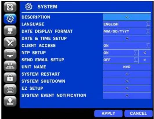
4-2. Setup - SYSTEM
In the SETUP menu, select the SYSTEM tab. Then, the SYSTEM menu is displayed as pictured below.
Navigate through the menu items or change the settings using the mouse or the remote control.
text_image
SYSTEM DESCRIPTION LANGUAGE DATE DISPLAY FORMAT DATE & TIME SETUP CLIENT ACCESS NTP SETUP SEND EMAIL SETUP UNIT NAME SYSTEM RESTART SYSTEM SHUTDOWN EZ SETUP SYSTEM EVENT NOTIFICATION ENGLISH MM/DD/YYYY ON ON OFF NVR APPLY CANCELFigure 4.2.1. SYSTEM Setup Screen
Table 4.2.1. Menu Items in SYSTEM Setup Screen
Item
Description
DESCRIPTION
Press the button to view the system information. (Software Version, Storage Size, IP Address, MAC Address and DDNS Status)
| MODEL NAME | N8NSL |
| SOFTWARE VERSION | Ver 4.4.0_20141124 |
| STORAGE SIZE | 1740 GB |
EU: Applies the EU daylight saving time.
- Select the GMT AREA using the mouse or the remote control.
- Set the time difference with the standard time using the mouse or the button.
OTHERS: If the time zone is neither USA nor EU, set the date and time of the daylight saving period.
- Select BEGIN or END.
Caution
- Do not set the start time to 23:00 for DLS.
- DLS cannot be applied if the date of BEGIN and END is the same.
Enable/Disable remote access through the network.
ACCESS
NTP
SETUP
NTP (Network Time Protocol) which synchronizes the time of the computer systems over variable-latency data networks.

text_image
PRIMARY SNTP SERVER Pool.ntp.org SECONDARY SNTP SERVER Time.nist.gov TIME ZONE GMT -5:00 (Montreal/New York) CONNECTION MODE TIME CONNECTION PERIOD 03:00 AM OK CANCELPRIMARY SNTP SERVER: Input the address of the primary NTP time-server.
SECONDARY SNTP SERVER: Input the address of the secondary NTP time-server.
TIME ZONE: NTP synchronizes with GMT (Greenwich Mean Time) regardless of geography; user must select time difference from GMT.
CONNECTION MODE: Select the NTP time-server connection mode from TIME
SEND EMAIL
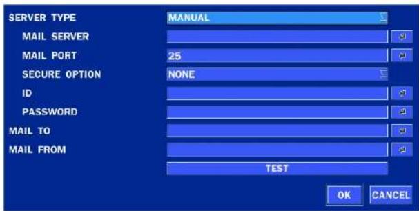
text_image
SERVER TYPE MAIL SERVER MAIL PORT SECURE OPTION ID PASSWORD MAIL TO MAIL FROM MANUAL 25 NONE TEST OK CANCELSERVER TYPE: Select GMAIL, HOTMAIL, AOL, YAHOO or MANUAL)
MAIL SERVER: Enter the appropriate mail server information.
MAIL PORT: Assign Mail Port number.
SECURE OPTION: Select the secure mail server connection method. (SSL or TLS)
ID: Enter the appropriate mail server ID.
PASSWORD: Enter the appropriate mail server PASSWORD
MAIL TO: Enter the appropriate email address to enable sending e-mail reports using a virtual keyboard.
MAIL FROM: To set the email address sent to the destination host.
TEST : E-mail settings sent a test mail to the registered account
UNIT NAME
Name the NS (e.g. Factory)
This feature is to identify the name of the NS under the same network.
SYSTEM
Restart the system
RESTART
SYSTEM
Shut down the system
(Allows the user to set MAIL STATUS periodically) : DAILY or WEEKLY or MONTHLY

text_image
PERIOD DAILY FIRST SUN 0 H OK CANCELEVENT AND NOTIFICATION - OFF, ON
HEALTH CHECK / RESTART / SHUTDOWN / PANIC RECORD
- Enable Email Notification in the event a problem occurs.
MOTION DETECTION – Enable Email Notification when the camera detects motion.
NO CONNECTION – Enable Email, Beep and Alarm output Notification when the camera signal is lost.
HDD TEMPERATURE – Enable Email, Beep and Alarm output Notification when the HDD temperature.
HDD BAD SECTORS – Enable Email Notification when the HDD has bad Sectors.
HDD ALMOST FULL – Enable Email Notification when the HDD is almost full
HDD FULL – Enable Email Notification when the HDD is full
HDD FAILURE – Enable Email, Beep and Alarm output Notification when the HDD fails.
4-3. Setup - RECORD Mode
In the SETUP menu, select the RECORD tab. Then, the RECORD menu is displayed as pictured below.
Navigate through the menu items or change the settings using the mouse or the remote control.

text_image
RECORD SITE CH 1Table 4.3.1. Menu Items in RECORD Setup Screen
| Menu Item | Description | |||
| SITE | Select a channel for applying the following settings using the mouse or the remote control. To change the values of all channels, take the following steps. Select the button to change the values of all channels. | |||
| RECORDING | PRE RECORD | POST EVENT REC | AUDIO | |
| ALL CONTINUOUS | 1 MIN(S) | 10 SEC(S) | OFF | |
| 1 CONTINUOUS | 1 MIN(S) | 10 SEC(S) | OFF | |
| 2 CONTINUOUS | 1 MIN(S) | 10 SEC(S) | OFF | |
| 3 CONTINUOUS | 1 MIN(S) | 10 SEC(S) | OFF | |
| 4 CONTINUOUS | 1 MIN(S) | 10 SEC(S) | OFF | |
| 5 CONTINUOUS | 1 MIN(S) | 10 SEC(S) | OFF | |
| 6 CONTINUOUS | 1 MIN(S) | 10 SEC(S) | OFF | |
| 7 CONTINUOUS | 1 MIN(S) | 10 SEC(S) | OFF | |
| 8 CONTINUOUS | 1 MIN(S) | 10 SEC(S) | OFF | |
| OK CANCEL | ||||
| RECORDING MODE | Assign the recording mode for the selected channel. | |||
| Options are: Continuous, Motion, Schedule or Disable. | ||||
| SENSOR RECORDING | Select the sensor setting for the selected channel. | |||
| Sensor recording only works with alarm contacts on the IP camera | ||||
| PRE RECORD | Enable/disable pre-event recording. Pre-event recording time is up to 20 minutes. | |||
| POST EVENT RECORD | Set the post event recording time duration for the specified channel.(10~30 seconds) | |||
| AUDIO | Enable/disable audio recording for the specified channel.Works with audio contacts on the IP Camera | |||
| RECORDING | PRE RECORD | POST EVENT REC | AUDIO | |
| ALL CONTINUOUS | 1 MIN(S) | 10 SEC(S) | OFF | |
| 1 | CONTINUOUS | 1 MIN(S) | 10 SEC(S) | OFF |
| 2 | CONTINUOUS | 1 MIN(S) | 10 SEC(S) | OFF |
| 3 | CONTINUOUS | 1 MIN(S) | 10 SEC(S) | OFF |
| 4 | CONTINUOUS | 1 MIN(S) | 10 SEC(S) | OFF |
| 5 | CONTINUOUS | 1 MIN(S) | 10 SEC(S) | OFF |
| 6 | CONTINUOUS | 1 MIN(S) | 10 SEC(S) | OFF |
| 7 | CONTINUOUS | 1 MIN(S) | 10 SEC(S) | OFF |
| 8 | CONTINUOUS | 1 MIN(S) | 10 SEC(S) | OFF |
SCHEDULE Set the recording schedule
4-3-1. Recording Schedules
To setup a recording schedule, select SCHEDULE in the RECORD menu. Navigate through the menu items or change the settings using the mouse or the remote control.
Select CHANNEL > select NONE, CONTINUOUS or MOTION > Highlight area
To copy a schedule to a different channel, select the channel from the COPY SCHEDULE menu.

text_image
CHANNEL 1 NONE CONTINUOUS MOTION SENSOR CLEAR 0 1 2 3 4 5 6 7 8 9 10 11 12 13 14 15 16 17 18 19 20 21 22 23 SUN MON TUE WED THU FRI SAT COPY SCHEDULE CH 1 CH 2 CH 3 CH 4 ALL CH 5 CH 6 CH 7 CH 8 CH 9 CH 10 CH 11 CH 12 CH 13 CH 14 CH 15 CH 16 COPY OK CANCELFigure 4.3.2. Schedule Recording Setup Screen
• NONE: Disable recording during selected timeframe (Highlighted in White)
• CONTINUOUS: CONTINUOUS recording (Highlighted in Green)
• MOTION: MOTION recording (Highlighted in Yellow)
• SENSOR: SENSOR recording (Highlighted in Red)
- CLEAR: Clears the schedule
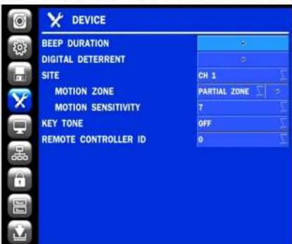
4-4. Setup - DEVICE Mode
In the SETUP menu, select the DEVICE tab. Then, the device menu is displayed as pictured below. Navigate through the menu items or change the settings using the mouse or the remote control.
text_image
DEVICE BEEP DURATION DIGITAL DETERRENT SITE MOTION ZONE MOTION SENSITIVITY KEY TONE REMOTE CONTROLLER ID CH 1 PARTIAL ZONE 7 OFF 0Figure 4.4.1. DEVICE Setup Screen
Table 4.4.1. Menu Items in DEVICE Setup Screen
| Item | Description |
| BEEP | Set beep dwell time from 5 to 60 seconds or infinite. |
| DURATION |
DIGITAL
Setup schedule and audio recordings for Digital Deterrent
4-4-1. Digital Deterrent
Trigger audio message via motion detection or sensor.

text_image
IMPORT FROM USB ... EXPORT TO USB ... RECORD ... SCHEDULE ... OKFigure 4.4.2. Digital Deterrent setup screen
Table 4.4.2. Item for Digital Deterrent Setup Screen
| Item | Description |
| IMPORT FROM USB | Import up to 8 sound files from USB. |
| EXPORT TO USB | Export the sound file to USB |
| RECORD | Select a channel and set up the date and the duration.And, select the sound file to play. |
 |
4-4-2. Motion Zone Setup
Select MOTION ZONE using the mouse or the remote control and select either PARTIAL ZONE or FULL ZONE using the mouse control. The default value is FULL ZONE.
If FULL ZONE is selected, the motion zone grid screen is not displayed. Only set the level of sensitivity for MOTION SENSITIVITY.
FULL ZONE: The motion sensor is active on the whole screen.
PARTIAL ZONE: The motion sensor is active in the set detection frame.
Select the motion detection position using the mouse or the remote control. Then left click on the mouse or left click and drag the mouse pointer to select or deselect the area. Highlighted area indicates the partial motion detection zone. Press the ESC button or right click on the mouse to return to the previous menu.

natural_image
Interior view of a modern museum or exhibition hall with glass display cases and wooden flooring (no visible text or signage)4-5. Setup - DISPLAY Mode
In the SETUP menu, select the DISPLAY tab. Then, the DISPLAY menu is displayed as pictured below. Navigate through the menu items or change the settings using the mouse or the remote control. To return to the previous setup menu screen, press the ESC button.

text_image
DISPLAY OSD OSD CONTRAST MAIN MONITOR SEQUENCE SEQUENCE-DWELL TIME SITE NAME COVERT VIDEO OUTPUT 100 ON 3 SECOND(S) CH 1 CH1 OFF 1280 x 720 APPLY CANCELFigure 4.5.1. DISPLAY Setup Screen
Table 4.5.1. Menu Items in DISPLAY Setup Screen
| Item | Description |
| OSD | Enable/Disable on-screen-display.(Channel Name, Video Loss, Status Bar / Icon) |
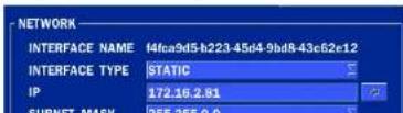
4-6. Setup - NETWORK Mode
Select the NETWORK tab. Then, the network menu is displayed as pictured below. Navigate through the menu items or change the settings using the mouse or the remote control.

text_image
NETWORK NETWORK TYPE IP 172.16.2.41 SUBNET MASK 255.255.0.0 GATEWAY 172.16.1.254 DNS (PRIMARY) 168.126.63.1 DNS (SECONDARY) 168.126.63.2 DDNS 5445 NETWORK PORT NETWORK AUDIO PORT 5446 WEB PORT 80Figure 4.6.1. NETWORK Setup Screen
Table 4.6.1. Menu Items in NETWORK Setup Screen
| Item | Description |
| NETWORK TYPE | DHCP: ZS will automatically retrieve an IP address. STATIC: Network information must be manually configured. |
| IP | Enter IP address that is assigned |
| SUBNET MASK | Enter Subnet Mask that is assigned |
| GATEWAY | Enter Gateway that is assigned |
4-6-1. Network Types
4-6-1-1. DHCP
An IP address is automatically assigned by the DHCP server, which automatically assigns the IP address and other parameters to new devices.
4-6-1-2. STATIC
IP address, Subnet Mask, Gateway, and DNS are manually assigned by the user.
• IP ADDRESS: The fixed IP address of the NSL unit.
- SUBNET MASK: The subnet mask for the LAN.
• GATEWAY: The IP address of the Gateway.
• DNS (PRIMARY) The primary address of Domain Name Server
• DNS (SECINDARY): The secondary address of Domain Name Server

NOTE
Unless DNS is properly set, the DDNS and the e-mail features will not work.
4-6-2. DDNS
DDNS (Dynamic Domain Name System) allows a DNS name to be constantly synchronized with a dynamic IP address. It allows using a dynamic IP address to be associated with a static domain name.
Once the setting is completed, the DDNS address will be:
http://hostname.ddns.specoddns.net
For example, if you enter the host name as "NS", then the address will be:
http://NS.ddns.specoddns.net
Select NETWORK>DDNS. The menu displays as below.
4-6-3. Network Port and Web Port
Connecting NSL through a common IP sharing device, each NSL must be assigned a unique TCP port number for access from outside the LAN. This port number is displayed on NETWORK>NETWORK PORT Setup MENU.

NOTE:
If you access the NSL only within the same LAN, the TCP port number does not need to be changed.
Network access beyond a router
To access NSL beyond a router (firewall), you must open the proper TCP ports for live/playback streaming, for commands, for remote backup, and for audio streaming. If these ports are not opened properly, you can't access the NSL beyond a router.

For live/playback streaming, for commands, for remote backup: Open the port number on NETWORK>NETWORK PORT menu. The default port number is 5445.
For bi-directional audio: Open the port number on NETWORK AUDIO PORT. The default port number is [NETWORK PORT number + 1].
For web-viewer downloading and remote firmware upgrading: Open the port number on NETWORK>WEB PORT menu. The default port number is 80.
- For IP Camera Setup through web viewer: Forward ports 59011 \~ 59254 to the NVR.
4-7. Setup - USER MANAGEMENT Mode
In the SETUP menu, select the USER MANAGEMENT tab. Then, the USER MANAGEMENT menu is displayed as pictured below. Navigate through the menu items or change the settings using the mouse or the remote control.

text_image
USER MANAGEMENT AUTHORITY SETUPTable 4.7.1. Menu Items in USER MANAGEMENT Setup Screen
| Item | Description | ||||
| AUTHORITY | Only the Admin will have access to the menu. | ||||
| SETUP | PASSWORD CHECK: Select the Checkbox to enable the functions or leave theCheckbox blank to disable the functions. | ||||
| SETUP: Enable/Disable of access to SetupPB: Enable/Disable of access to PlaybackREC OFF: Enable/Disable of manual RecordNETWORK: Enable/Disable of access to Network | |||||
| Selected Checkbox: The NSL will ask for a password when the given function isselected for all users. | |||||
| Blank Checkbox: The NSL will not ask for a password when the given function isselected for all users. | |||||
| PASSWORD | SETUP | PB | REC OFF | ||
| PASSWORD CHECK | × | × | × | ||
| ADMIN | 1111 | × | × | × | |
| USER1 | 1111 | × | × | × | |
| USER2 | 1111 | × | × | × | |
| USER3 | 1111 | × | × | × | |
| OK | |||||
| CANCEL | |||||
| ADMIN, USER1, USER2, USER3:Selected Checkbox: The user can access the function.Blank Checkbox: The user can not access the function. | |||||
| USER NAME | Change the name of USER1, USER2 and USER3. | ||||
| SETUP | ● Click "ENTER" after naming. | ||||
| PASSWORD | Passwords can be changed for ADMIN, USER1, USER2 and USER3. | ||||
| PASSWORD | SETUP | PB | REC OFF | NETWORK | |
| PASSWORD CHECK | ▼ | ▼ | ▼ | ▼ | |
| ADMIN | 1111 | ▼ | ▼ | ▼ | ▼ |
| USER1 | 1111 | ▼ | ▼ | ▼ | ▼ |
| USER2 | 1111 | ▼ | ▼ | ▼ | ▼ |
| USER3 | 1111 | ▼ | ▼ | ▼ | ▼ |
REMOTE Disconnect the remote playback after the specific time (Disable, 5min, 10min, 15 min, PLAYBACK 30min, 60min.
TIMEOUT
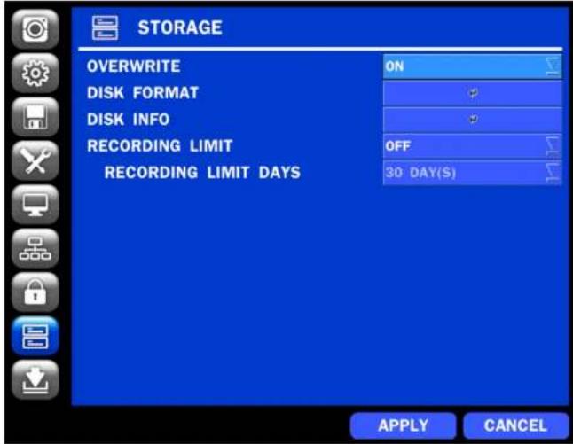
4-8. Setup - STORAGE Mode
In the SETUP menu, select the STORAGE tab. Then, the STORAGE menu is displayed as pictured below. Navigate through the menu items or change the settings using the mouse or the remote control.
text_image
STORAGE OVERWRITE ON DISK FORMAT # DISK INFO # RECORDING LIMIT OFF 30 DAY(S) RECORDING LIMIT DAYS APPLY CANCELFigure 4.8.1. STORAGE Setup Screen
| MODEL NAME | TEMPERATURE | HEALTH(GOOD/NORMAL/BAD) | |
| HDD 1 | WDC WD20EURS-73S48Y0 | 42 C (107 F) | GOOD |
| HDD 2 | WDC WD20EVDS-63T3B0 | 48 C (118 F) | GOOD |
| HDD 3 | WDC WD20EVDS-63T3B0 | 48 C (118 F) | GOOD |
| HDD 4 | |||
| HDD 5 | |||
| HDD 6 |
RECORDING LIMIT
Enable recording limit: The amount of data recorded in HDD will be limited to the most recent number of days as set by "RECORDING LIMIT DAYS".
Disable recording limit: When OVERWRITE is ON, DVR will continue to record when HDD is full and overwrite older data. When OVERWRITE is OFF, DVR will stop recording when the HDD is full.
Set the recording limit days. (1- 90 days)
If the RECORDING LIMIT DAYS are set to 1, the data will be overwritten after 24 hours.
4-9. Setup - CONFIG Mode
In the SETUP menu, select the CONFIG tab. Then, the configuration menu is displayed as pictured below. Navigate through the menu items or change the settings using the mouse or the remote control.


CONFIG
Table 4.9.1. CONFIGURATION Setup
| Item | Description |
| EXPORT TO USB | User can save the current configuration settings of the NSL to a USB flash drive. Plug in the USB flash on the front panel and press the button to start the export process. |
| IMPORT FROM USB | User can upload the configuration of the NSL to another NSL using the USB Flash drive. Plug in the USB flash drive on the front panel and press the button to start the import process. |
| LOAD DEFAULT | Select this option to reset the system to the default settings.The following settings such as Language, ID, Security User Authentication, Security User P/W, Date format, DLS settings, Network settings, HDD overwrite, Limit recording, HDD serial number, and HDD ERROR time will not be included. |
| LOAD FACTORY DEFAULT | Press the button to reset the system to the factory default settings. |
| SOFTWAREUPGRADE | Upgrade software to the latest version.After connecting USB flash drive to USB port on the NSL, click SEARCH.It will automatically find the upgrade file. |
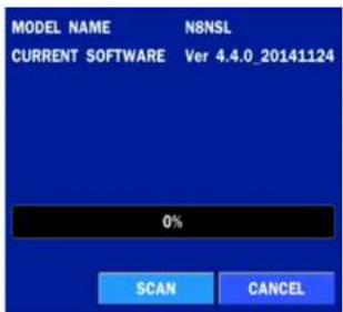
4-9-1. Firmware Upgrade
- Create a new folder named "upgrade" in the USB flash drive root directory.
-
Create sub-folder for each model under "upgrade" folder and copy each firmware.
-
N4NSL: main_n4nsl_speco_.*.*_201****
• 2014年 , 2015年 ,
text_image
MODEL NAME N8NSL CURRENT SOFTWARE Ver 4.4.0_20141124 0% SCAN CANCELFigure 4.9.2
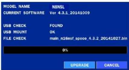
text_image
MODEL NAME N8NSL CURRENT SOFTWARE Ver 4.3.1_20141009 USB CHECK FOUND USB MOUNT OK FILE CHECK maln_n16nsf.speco_4.3.2_20141027.bin 0% UPGRADE CANCELFigure 4.9.3
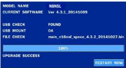
text_image
MODEL NAME NSNSL CURRENT SOFTWARE Ver 4.3.1_20141009 USB CHECK FOUND USB MOUNT OK FILE CHECK main_n16nsf_speco_4.3.2_20141027.bin 100% UPGRADE SUCCESS RESTART NOWFigure 4.9.4
NOTICE

- If selecting REBOOT NOW when the USB flash drive is plugged, the following message will pop up: Remove the USB flash drive and select OK.

text_image
SEARCH SETUP DISPLAY SNAPSHOT SUPER EZ COPY ENABLE MANUAL RECORD INSTANT PLAYBACK ADVANCED MENU EZ SETUP CONNECT AUDIO MUTE CAMERA PTZ ENABLE MAIN MONITOR SEQUENCE DISABLE ALARM OUT MANUAL DIGITAL DETERRENT CAMERA INFORMATION SYSTEM INFORMATION EXPORT HELP SYSTEM LOCK SYSTEM SHUTDOWN CH1 CH2 CH3 CH4 CH5 CH6 CH7 CH8 CH9 CH10 CH11 CH12 CH13 CH14 CH15 CH16 CH17 CH18 CH19 CH20 CH21 CH22 CH23 CH24 CH25 CH26 CH27 CH28 CH29 CH30 CH31 CH32 CH33 CH34 CH35 CH36 CH37 CH38 CH39 CH40 CH41 CH42 CH43 CH44 CH45 CH46 CH47 CH48 CH49 CH50 CH51 CH52 CH53 CH54 CH55 CH56 CH57 CH58 CH59 CH60 CH61 CH62 CH63 CH64 CH65 CH66 CH67 CH68 CH69 CH70 CH71 CH72 CH73 CH74 CH75 CH76 CH77 CH78 CH79 CH80 CH81 CH82 CH83 CH84 CH85 CH86 CH87 CH88 CH89 CH90 CH91 CH92 CH93 CH94 CH95 CH96 CH97 CH98 CH99 CH100 0.0.0 05/29/2013 15:42:10 RC: ALL HDD: OVERWRITEFigure 5.1.1. Live Screen and Quick Operation Window
Table 5.1.1. Status Indicator Icons in Live Viewing Screen
| Icon | Description |
| [5GBH] | Indicates the NSL is locked.Note) to unlock, right click on the live view screen and click on Unlock. |
 | Audio mute.To select audio output, press the Audio after click the right button on the mouse.Toggle from Audio 1 to 4, mute in order. |

15%
Displays the amount of recording on the hard disk from 0-99%.

Indicates that HDD is recycled.

Continuous recording in progress.

Manual recording in progress. To set the Manual recording mode, press the Record button on the front panel.

Motion alarm recording in progress.

Sensor recording in progress.
Right click the mouse, and the quick operation window will be displayed as below.
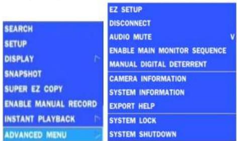
text_image
SEARCH SETUP DISPLAY SNAPSHOT SUPER EZ COPY ENABLE MANUAL RECORD INSTANT PLAYBACK ADVANCED MENU EZ SETUP DISCONNECT AUDIO MUTE V ENABLE MAIN MONITOR SEQUENCE MANUAL DIGITAL DETERRENT CAMERA INFORMATION SYSTEM INFORMATION EXPORT HELP SYSTEM LOCK SYSTEM SHUTDOWNFigure 5.1.2. Quick Operation Window
Table 5.1.2. Menu Items in Quick Operation Window
ADVANCED MENU
| EZ SETUP | Select this option to start EZ Setup Wizard. |
| CONNECT | Select this option to disconnect/connect from IP Camera. |
| AUDIO MUTE | Select this option to mute audio on all channels. |
| ENABLE MAIN MONITOR SEQUENCE | Sequence button. Click this button to use a sequence function. |
| DISABLE ALARM OUT | Click this button to enable/disable Alarm outputs |
MANUAL Select this option to manually trigger any of the saved Digital DIGITAL DETERRENT Deterrent messages.

text_image
Manual Digital Deterrent Select Digital Deterrent Source Source Name Default OK CLOSECAMERA Press the button to view the record setting of a selected channel.
| IP CAMERA INFORMATION | |||||
| CH | VENDOR | IP ADDRESS | RESOLUTION | FRAME RATE (FPS) | BIT RATE (Kbps) |
| 1 | ONSIP | 10.20.30.11 | 1920 x 1090 | 30 | 1773 |
| 2 | VIP | 10.20.30.12 | 1920 x 1090 | 15 | 3907 |
| 3 | VIP | 10.20.30.20 | 1920 x 1080 | 22 | 3514 |
| 4 | VIP | 10.20.30.14 | 1920 x 1080 | 23 | 3500 |
| 5 | VIP | 10.20.30.16 | 1280 x 1024 | 30 | 3902 |
| 6 | ONSIP | 10.20.30.19 | 1280 x 1024 | 13 | 660 |
| 7 | VIP | 10.20.30.17 | 1280 x 720 | 30 | 1510 |
| 8 | VIP | 10.20.30.18 | 1920 x 1080 | 22 | 3413 |
| TOTAL | 188 | 22479 | |||
| CLOSE | |||||
SYSTEM Press the button to view the system information.
5-2. Digital Zoom in Live and Playback Screen
NSL series supports Digital Zoom feature during live and playback mode.
- Double click the target channel.

text_image
CH 2 CH 5 CH 6- Click the left button of the mouse and drag to make rectangular shape.
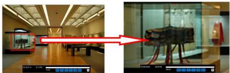
natural_image
Two-panel image showing a museum interior with a close-up of a display case and an ancient artifact on display (no visible text or symbols)5-3. SEARCH Screen
To enter the search screen menu, select SEARCH menu on the screen using the mouse or press SEARCH icon on live screen.
5-3-1. EZSearch
The EZSearch window is used to find stored video with ease using the thumb nail playback screen.

text_image
May, 2013 Sun Mon Tue Wed Thu Fri Sat 5 6 7 8 9 10 11 12 13 14 15 16 17 18 19 20 21 22 23 24 25 26 27 28 29 30 31 < PREV NEXT > CLOSEFigure 5.3.2. Calendar Screen
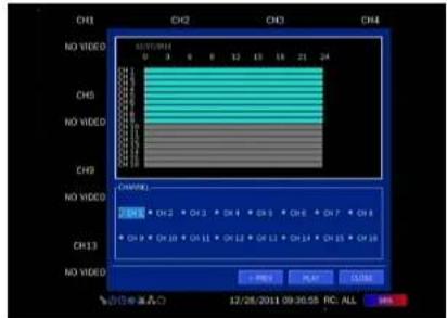
text_image
CH1 CH2 CH3 CH4 NO VIDEO 0 3 6 8 12 15 18 21 24 CHS NO VIDEO CHS NO VIDEO CHWNL CH1 CH2 CH3 CH4 CH5 CH6 CH7 CH8 CH9 CH10 CH11 CH12 CH13 CH14 CH15 CH16 CH13 NO VIDEO START PLAY CLOSE © 2011.09.30.55 RC ALLFigure 5.3.3. Channel Selection Screen

text_image
Grid of surveillance cameras with a red highlight highlighting the '40000' lens, likely from an optical or medical imaging system.Figure 5.3.4. 24 Hourly Thumbnail Screen
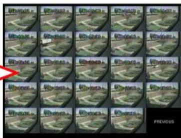
text_image
PreviousFigure 5.3.5. Minute Thumbnail Screen

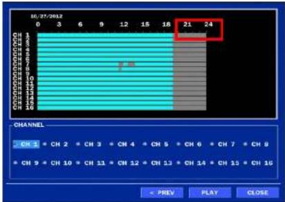
5-3-2. Time Line Search
The CALENDAR Search window is used to find the stored video by using the time line bar.

text_image
May, 2013 Sun Mon Tue Wed Thu Fri Sat 5 6 7 8 9 10 11 12 13 14 15 16 17 18 19 20 21 22 23 24 25 26 27 28 29 30 31 < PREV NEXT > CLOSEFigure 5.3.7. Calendar Screen
bar
| Channel | Value | |---|---| | Channel 1 | 21 | | Channel 2 | 24 | CHANNEL CH 1 CH 2 CH 3 CH 4 CH 5 CH 6 CH 7 CH 8 CH 9 CH 10 CH 11 CH 12 CH 13 CH 14 CH 15 CH 16 = PREV PLAY CLOSEFigure 5.3.8. Time-Line Search Screen
When the Timeline menu is selected, the user can see a calendar, which displays recorded dates with highlights. Select a specific date and time. Click and drag the red time indicator bar to the desired hour. User can select a specific minutes using a button in the above red box. Press the PLAY button after selecting the specific time. Press the PREV to return to the SEARCH window.
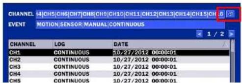
5-3-3. Event Search
The Event Search window is used to find stored video.
text_image
CHANNEL 14|CH5|CH6|CH7|CH8|CH9|CH10|CH11|CH12|CH13|CH14|CH15|CH EVENT MOTION|SENSOR|MANUAL|CONTINUOUS CHANNEL LOG DATE CH1 CONTINUOUS 10/27/2012 00:00:01 CH2 CONTINUOUS 10/27/2012 00:00:01 CH3 CONTINUOUS 10/27/2012 00:00:01 CH4 CONTINUOUS 10/27/2012 00:00:01 CH5 CONTINUOUS 10/27/2012 00:00:01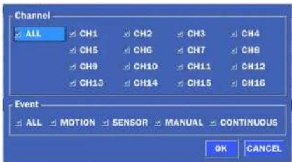
text_image
Channel ALL CH1 CH2 CH3 CH4 CH5 CH6 CH7 CH8 CH9 CH10 CH11 CH12 CH13 CH14 CH15 CH16 Event ALL MOTION SENSOR MANUAL CONTINUOUS OK CANCELFigure 5.3.10. Event Search Screen
5-3-4. Go To First Time
User can access from the oldest recorded data on the NSL hard drive by selecting GO TO FIRST TIME on the SEARCH window. Press the PREV to return to the SEARCH window.
5-3-5. Go To Last Time
User can access from the last minute recorded data on the NSL hard drive by selecting GO TO LAST TME on the SEARCH window. Press the PREV to return to the SEARCH window.
5-3-6. Go To Specific Time
User can search for video data from a specific instance by setting the date and time in the GO TO SPECIFIC TIME menu. Use the mouse or the remote control to change the date and time value and press the PLAY button after setting. If there is no video data in the set date and time, No Data Exist message displays.
5-3-7. Archive List
The ARCHIVE Search window is used to find previously stored video or images.
5-3-8. Log List
You can access the LOG list search screen by selecting LOG on the SEARCH window.
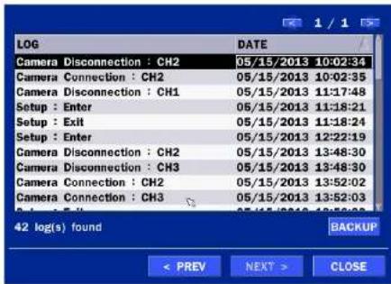
text_image
LOG Camera Disconnection : CH2 Camera Connection : CH2 Camera Disconnection : CH1 Setup : Enter Setup : Exit Setup : Enter Camera Disconnection : CH2 Camera Disconnection : CH3 Camera Connection : CH2 Camera Connection : CH3 42 log(s) found DATE 05/15/2013 10:02:34 05/15/2013 10:02:35 05/15/2013 11:17:48 05/15/2013 11:18:21 05/15/2013 11:18:24 05/15/2013 12:22:19 05/15/2013 13:48:30 05/15/2013 13:48:30 05/15/2013 13:52:02 05/15/2013 13:52:03 05/15/2013 13:52:03 BACKUP < PREV NEXT > CLOSEFigure 5.3.12. Log List Screen
When the Log menu is selected, the user can see a calendar, which has a log data. Select a specific date and press NEXT button, and then the log data will be displayed. Press the SAVE button to save the data and then the data is saved as a text file format.
5-4. Play Mode
During playback of a recorded event, the mode changes from SEARCH to PLAY. While in PLAY mode, user may return to the SEARCH screen by pressing the X button on the status bar.

natural_image
Exterior view of a modern industrial or construction site with buildings, utility poles, and trees (no visible text or signage)Table 5.4.1. Button Functions in PLAY Mode
| Button | Description |
 | 2x, 4x, 8x,16x, 32x speeds at 2x2 screen display mode.2x, 4x, 8x,16x speeds at 3x3 screen display mode.2x, 4x, 8x speeds at the 4x4 screen display mode.Single Channel backward playback speed 1x, 2x, 4x, 8x, 16x, 32x, 64x |
 | Jump/Step backward. The playback position moves 60 seconds backward. |
 | Press to play or pause recorded video. |
| [YS83] | Jump/Step forward. Playback position moves 60 seconds forward. |
 | 2x, 4x, 8x,16x, 32x speeds at 2x2 screen display mode2x, 4x, 8x,16x speeds at 3x3 screen display mode.2x, 4x, 8x speeds at the 4x4 screen display mode.Single Channel forward playback speed 1x, 2x, 4x, 8x, 16x, 32x, 64x |
 | Slow Mode play. Forward playback speed x1/4, x1/2 |
 | Press to backup the video. |
 | EZCopy button. |
 | Return to the previous menu screen, search window, or exit from the Menu. |
6. Back Up
6-1. Still Image Backup onto USB Flash Drive
Still images can be captured and archived onto a USB flash drive or an USB external hard drive in live mode or while playing back recorded video.
- Select a specific channel, which wants to backup on live screen.
- When you press SNAPSHOT button on Quick operation window, the media selection window screen will display.
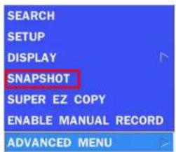
text_image
SEARCH SETUP DISPLAY SNAPSHOT SUPER EZ COPY ENABLE MANUAL RECORD ADVANCED MENU
text_image
PLEASE SELECT MEDIA TYPE USE DRIVE H PREV START CLOSE- Once you press START button, the system will capture a still image and archive onto a USB flash drive.

NOTICE
USB Flash Drive must be in FAT32 file format.
6-2. Video Backup onto USB Flash Drive during playback
Video can be captured and archived onto the USB flash drive or a hard drive while playing back the

text_image
PLEASE SELECT MEDIA TYPE ○ USB DRIVE < PREV START CLOSE- Select USB STICK DRIVE (Flash Drive) to back up less than an hour. Select USB HDD (Large Backup) to back up from 1 hour to 24 hours.

text_image
PLEASE SELECT MEDIA TYPE • USB DRIVE • USB HDD (LARGE BACKUP) CALCULATION < PREV NEXT > CLOSE- Once you select the channel and duration, the system will start to archive the data to the USB drive.
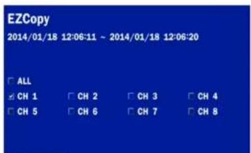
text_image
EZCopy 2014/01/18 12:06:11 ~ 2014/01/18 12:06:20 □ ALL □ CH 1 □ CH 2 □ CH 3 □ CH 4 □ CH 5 □ CH 6 □ CH 7 □ CH 8
text_image
100% COMPLETE PREV START CLOSE6-2. EZCopy: Video Backup onto USB Flash Drive during playback
Using EZCopy feature, Video can be easily archived onto the USB flash drive or a hard drive.
In playback mode, press the EZ COPY button to launch the backup function.
- Press EZCOPY button on the selected channel or all channels.

text_image
- 1/4 + EZ- Then, EZCOPY START time will display.

text_image
2011/10/10 03:33:- Move time bar cursor to the time of end of backup and press EZCOPY button. Then, EZCOPY

text_image
EZCopy 2014/01/10 00:00:06 ~ 2014/01/10 00:00:07 SELECT FILE FORMAT ○ NSF - PROPRIETARY FORMAT ○ AVI - INTEGRATED SUBTITLE ○ AVI - SEPARATED SUBTITLE, MAC COMPATIBLE CALCULATION < PREV NEXT > CLOSE- After backup format is selected, also select media type and channel(s) to archive the data to the media.
6-3. Transferring Still Images or Video from the ARCHIVE List
The stored data in the hard drive can be found in the ARCHIVE list in the SEARCH window.
User can back up still images or video into the storage device from the ARCHIVE list.
- Select the date to begin searching and navigate through the days using the mouse or the remote control.
- Once you have selected the date, press the NEXT button to open the list of stored data.
- Use the mouse or the remote control to scroll through the archive list.
- Select a list of stored events in the archive list.
- Once the desired event has been selected, press the DISPLAY button to view the still image or the first frame of the selected video.
- Press the BACKUP button to launch the archiving function in playback mode.
6-4. Playback of Backup Video
6-5-1. AVI Format
AVI format: AVI format video can be played back by Window Media Player™ or other media player that is compatible with AVI format video.
- Please install the NS copies "UMS Decoder Filter" folder on USB flash drive with the video.
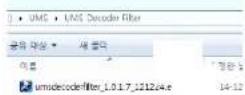
- Otherwise, the video and time stamp over video can't be properly playback and displayed on Window Media Player™.
natural_image
Interior view of a museum gallery with wooden flooring, display cases, and ceiling lighting (no visible text or signage)
Timestamp On AVI. The subtitle is embedded to the video clip file.
The subtitle is embedded to the AVI file. To display a subtitle, user should install a special filter called "UMSDecoderFilter".
6-5-2. NSF Format
7. Network Access Using the Multi-Sites Network Viewer
7-1. Overview
The SpecoTech Multi Client is a multiple site monitoring client software with; video, audio, and alarm signals from the NSL over the network. The SpecoTech Multi Client does not limit the number of NSL units to register.
The program displays up to 8 NSL units and supports dual monitors.
By attaching a microphone and speaker system to devices on site, the user may make bi-directional audio communication over the network.
7-2. PC Requirements
Minimum PC Requirements
| CPU | Intel Core i3 |
| 1.8Ghz | |
| Memory | 2GB DDR2 |
| VGA | 512MB |
| Resoluon | 1280x720 |
| Disk Space | 1GB |
| OS | Windows 2000, XP Professional, XP Home, Vista, 7 (NOTE: Not all versions of Vista and 7 are supported) |
| Network | 10/100Base T |
| Others | Direct X 9.0c or Higher |
Recommended PC Requirements
| CPU | Intel Core i5 |
7-3. Installation of the Program
- Insert the provided CD in the CD drive and double-click "SpecoTech Multi Client (XXXX).exe"
- Select a destination folder and click "Next".
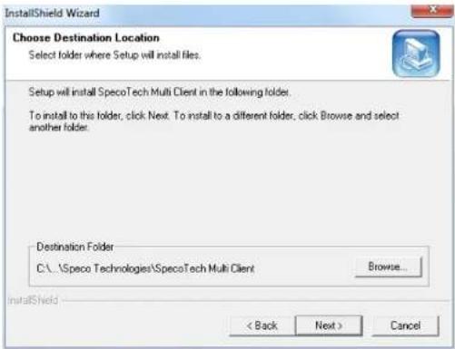
text_image
InstallShield Wizard Choose Destination Location Select folder where Setup will install files. Setup will install SpecoTech Multi Client in the following folder. To install to this folder, click Next. To install to a different folder, click Browse and select another folder. Destination Folder C:\.\Speco Technologies\SpecoTech Multi Client Browse... < Back Next > Cancel- Select the program folder and click "Next".
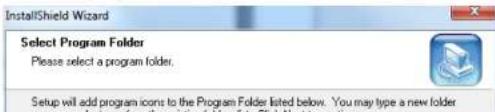
text_image
InstallShield Wizard Select Program Folder Please select a program folder. Setup will add program icons to the Program Folder listed below. You may type a new folder7-4. Live Window
When installation is completed, double click the "SpecoTech Multi Client" icon on your desktop to start the program.
7-4-1. Main User Interface
text_image
SPECO Multi Client Ver 3.1.2.57-4-2. Control Buttons
| Button | Description |
 LOCAL PLAYBACK LOCAL PLAYBACK | Click this icon to run a playback window to search and play videos that are recorded in the local PC. |
 | SETUP | Click this icon to setup configuration of MULTI CLIENT. |
 | CAPTURE | Click this icon to capture a still image. |
 | EVENT LIST | Opens list of events logged by Multi Client. |
 | PAUSE | Click this icon to play/pause live video. |
 | ALARM ON | Click this icon to turn on/off alarm outputs. |
 | RECORD ON | Enable or disable recording of live video to local disk, which has set in setup menu. |
 | Use the volume control bar to set the audio level. | |
 | MIC Use the microphone volume control bar to set the micro phone level. | |
 | User can control PRESET/TOUR/SCAN/MENU | |
| PRESET/TOUR/SCAN/MENU | ||
 |  | To select the numbers of display channel/channels (Single, quad, 9 channels, and 16 channels) of highlighted site. |
 |  | To select the numbers of NS/NSs (1 NS, 4 NSs, 9 NSs, 16 NSs) on main display screen. |
| NSL SITE SPLIT | ||
7-5. Search and Playback Window
7-5-1. Main User Interface
7-5-2. Main Control Panel
| Button | Description |
 LOCAL PLAYBACK LOCAL PLAYBACK | Click this icon to run a playback window to search and play videos that are recorded in the local PC. |
 REMOTE PLAYBACK REMOTE PLAYBACK | Click this icon to run a playback window to search and play videos that are recorded in the remote NS. |
 | THUMBNAIL REFRESH: Click this icon to refresh and renew thumbnail image of the connected sites.SITE ADDITION: Click this icon to open 'Site Addition' window.SITE DELETE: Click this icon to delete site from the index window, after disconnect a site.NET FINDER: Select the site from the index window and click this icon to modify the information of specific site. |
 CONNECT CONNECT | Click this icon to connect the selected site/sites. |
 DISCONNECT DISCONNECT | Click this icon to disconnect the selected site/sites. |
 ETUP ETUP | Click this icon to setup configuration of SpecoTech Multi Client. |
 CAPTURE CAPTURE | Click this icon to capture a still image. |
 | To select the channel to playback. | ||
 | The calendar shows dates with recorded video in color. | ||
 | To display the recorded data of selected channel or all channels on a time line scale. | ||
 | To change a timeline scale from 24 hours to 60 minutes.The timeline shows recorded data in color on the bar. You can adjust the timeline scale and move it to the time you wish to playback. Then click the play icon to display the recorded video. | ||
 | Playback buttons. | ||
 | Thumbnail search over the network.- List the thumbnail 24images from 00:00 to 23:00.- Select one of 24 images every 150sec for an hour.- Then play the tile* Click the "PREVIOUS" button to go the previous step. | ||
 | Digital Zoom Window in Live and Playback. (Only available in Single Channel Viewing) | ||
7-6. Setup of SpecoTech Multi Client

text_image
Setup General Event Event search Record Disk Display Language About Security Option Startup Shutdown Setup Local Playback Remote Playback Password... Save Path Capture : C:\Storage\Capture\ Backup : C:\Storage\Backup\ Miscellaneous Automatic reconnection Always On Top Time Format : YYYY-MM-DD OK Cancel7-6-2. Event
Event log can be archived and searched.
Event Log: Specify the location to save event logs and select event to archive.
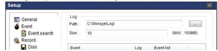
text_image
Setup General Event Event search Record Disk Log Path : C:\Storage\Log\ Size : 10 (MAX : 100MB) Event Log Event listEvent Search: Event log can be searched from the selected time.
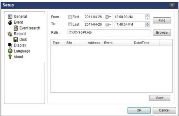
text_image
Setup General Event Event search Record Disk Display Language About From: First 2011-04-26 12:00:00 AM To: Last 2011-04-26 7:48:54 PM Path: C:\Storage\Log\( Type Site Address Event Date/Time Save OK Cancel7-6-3. Record
Record Setup: You can set the recording conditions as the following; Always, Event, or Auto record. And you can also select target NSL and channel/channels. When you set the recording condition to event, you can set event for motion or alarm with duration.

text_image
Setup General Record ConditionRecord Local Storage Setup: You can select the local disk to record and the amount of disk space you want to allow the program to use for recording. You can also select the option to overwrite data or stop recording when the maximum amount of disk space is full.

text_image
Setup General Event Event search Record Disk Display Language About Disk Space : C:\ 4 GB Disk Info Total space : 465 GB Free space : 398 GB Disk full Replace oldest files. Stop recording. OK Cancel7-6-4. Display
You can select the OSD (On Screen Display) to be displayed.
text_image
Setup General OSD7-6-5. Language
English, French and Spanish is selectable.
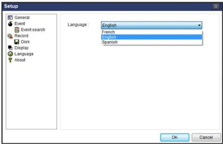
text_image
Setup General Event Event search Record Disk Display Language About Language: English French English Spanish OK Cancel7-6-6. About
"About" provides network client version information.
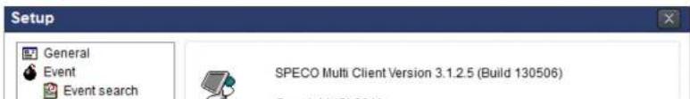
text_image
Setup General Event Event search SPECO Multi Client Version 3.1.2.5 (Build 130506)7-7. Remote Setup
The menu settings for the NSL unit can be set over network.
Put the cursor of the mouse on the channel, which is connected to the site and right click on the mouse to open the submenu. Then the following window is displayed as below. Select the REMOTE SETUP.
text_image
SPECO Multi Client SPECO Multi Client SPECO Multi Client SPECO Multi Client SPECO Multi Client SPECO Multi Client SPECO Multi Client SPECO Multi Client SPECO Multi Client SPECO Multi Client SPECO Multi Client SPECO Multi Client SPECO Multi Client SPECO Multi Client SPECO Multi Client SPECO Multi Client SPECO Multi Client SPECO Multi Client SPECO Multi Client SPECO Multi Client SPECO Multi Client SPECO Multi Client SPECO Multi Client SPECO Multi Client SPECO Multi Client SPECO Single Client SPECO Single Client SPECO Single Client SPECO Multi Client SPECO Single Client SPECO Single Client SPECO Multi Client SPECO Single Client SPECO Single Client SPECO Multi Client SPECO Single Client SPECO Single Client SPECO Multi Client SPECO Single Client SPECO Single Client SPECO Multi Client SPECO Single Client SPECO Single Client SPECO Multi Client SPECO Single Client SPECO Single Client SPECO Multi Client SPECO Single Client SPECO Single Client SPECO Multi Client SPCO Single Client SPECO Single Client SPECO Single Client SPECO Multi Client SPCO Single Client SPECO Single Client SPECO Single Client SPECO Multi Client SPCO Single Client SPECO Single Client SPECO Single Client SPECO Multi Client SPCO Single Client SPECO Single Client SPECO Single Client SPECO Multi Client SPCO Single Client SPECO Single Client SPECO Single Client SPECO Multi Client SPCO Single Client SPECO Single Customer Effect SPECO Multi Client SPCO Single Customer Effect SPECO Multi Client SPCO Single Customer Effect SPECO Multi Client SPCO Single Customer Effect SPECO Multi Client SPCO Single Customer Effect SPECO Multi Client SPCO Single Customer Effect SPECO Multi Client SPCO Single Customer Effect SPECO Multi Client SPCO Single Customer Effect SPECO Multi Client SPCO Single Customer Effect SPECO Multi Client SPCO Single Customer EffectThen the setup window is displayed. The specified menu screen is displayed on the upper left of the screen. Enter the password of the NSL when prompted. (NOTE: The default password is 1111)
Setting is the same as with the NS menu setting. Refer to the corresponding pages for details on the setting items.

text_image
SPECO WEB SETUP 17216.2.62 (cgl bin/websetup.cgl)7-7-1. IP Camera
Select IP Camera to set system and time settings
SPECO WEB SETUP
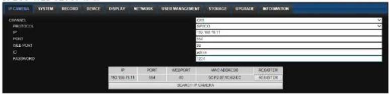
text_image
IP CHANNEL SYSTEM RECORD DEVICE DISPLAY NETWORK USER MANAGEMENT STORAGE UPGRADE INFORMATION CHANNEL PROTOCOL IP PORT VALL PORT ID PASSWORD IP PORT WEI PORT MAC ADDRESS REGISTER 192.168.75.11 354 80 SO FD BY 10000000 REGISTER SEARCH IP CAMERA7-7-2. System
Select System to set system and time settings.

text_image
IP CAMERA SYSTEM RECORD DEVICE DISPLAY NETWORK USER MANAGEMENT STORAGE UPGRADE INFORMATION DATE DISPLAY FORMAT MMOD/YYYY TIME DISPLAY FORMAT 24-HOUR FORMAT TIME ZONE GMT -5.00 (Montreal/New York) DAYLIGHT SAVING USA SET DATE & TIME SET DATE & TIME CLIENT ACCESS ON OFF NTP SETUP ON PRIMARY SNTP SERVER Pool.ntp.org SECONDARY SNTP SERVER Time.nst.gov TIME ZONE GMT -5.00 (Montreal/New York) CONNECTION MODE TIME CONNECTION PERIOD 03:00 AM SEND EMAIL SETUP OFF SERVER TYPE MAIL Server MAIL PORT RS SECURE OPTION ID PASSWORD- Time Zone: Select the time zone.
o Connection Mode: Select the connection mode to NTP time server.
- SEND E-Mail SETUP: Sets whether to enable/disable e-mail sending function.
- SEVER TYPE: Select GMAIL, HOTMAIL, AOL, YAHOO or MANUAL)
- MAIL SERVER: Input the SMTP server name as well as the user ID and password.
- MAIL PORT: Mail port setting.
- SEURE OPTION: Select a secure mail server connection. (SSL or TLS)
o ID : Email User ID
- PASSWORD : Email User Password
- MAIL TO: Input the appropriate email address to enable sending e-mail reports
- MAIL FROM (Return Mail Address): Set the source e-mail address to be notified to the destination.
- SEND MAIL TEST : E-mail settings sent a test mail to the registered account
• UNIT NAME: Name the HS
• SYSTEM RESTART : Restart the system
• SYSTEM EVENT NOTIFICATION
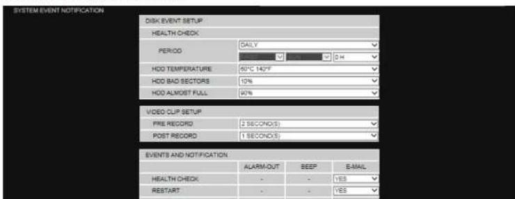
text_image
SYSTEM EVENT NOTIFICATION DISK EVENT SETUP HEALTH CHECK PERIOD DAILY 0 H HDD TEMPERATURE 60°C 140°F HDD BAD SECTORS 10% HDD ALMOST FULL 40% VIDEO CLIP SETUP FIRE RECORD 2 SECOND(S) POST RECORD 1 SECOND(S) EVENTS AND NOTIFICATION ALARM-OUT BEEP E-MAIL HEALTH CHECK - - YES RESTART - - YES- HEALTH CHECK / RESTART / SHUTDOWN / PANIC RECORD:
Enable Email Notification in the event a problem occurs with the NS. - ALARM-IN : Enable Email Notification when the camera detects sensor
- MOTION DETECTION : Enable Email Notification when the camera detects motion
- NO CONNECTION: Enable Email, Beep and Alarm output Notification when the camera signal is lost.
- HDD TEMPERATURE : Enable Email Beep and Alarm output Notification when the HDD reaches the maximum temperature
- HDD BAD SECTOR : Enable Email Notification when the HDD has bad sectors.
- HDD ALMOST FULL : Enable Email Notification when the HDD is almost full.
- HDD FULL : Enable Email Notification when the HDD is full.
- HDD FAILURE : Enable Email, Beep and Alarm output Notification when the HDD fails.
7-7-3. Record
Select RECORD tab to set the recording conditions.
SPECO WEB SETUP

text_image
IP CAMERA SYSTEM RECORD DEVICE DISPLAY NETWORK USER MANAGEMENT STORAGE UPGRADE INFORMATION SITE RECORDING MODE SENSOR RECORDING PRE RECORD POST EVENT RECORD AUDIO SCHEDULE NONE 0 1 2 3 4 5 6 7 8 9 10 11 12 13 14 15 16 17 18 19 20 21 22 23 RUN MON TUE YES TUG FIS SATSPECO WEB SETUP
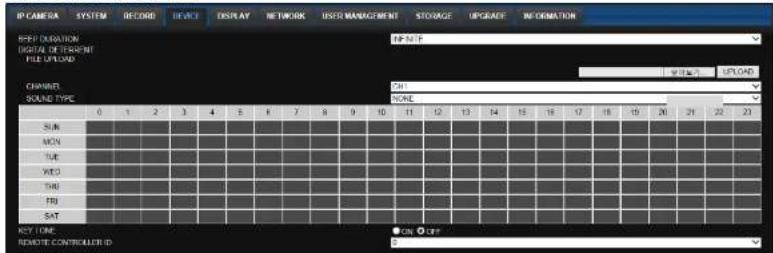
text_image
IP CAMERA SYSTEM RECORD DEVICE DISPLAY NETWORK USER MANAGEMENT STORAGE UPGRADE INFORMATION REEP DIMENSION DIGITAL DETERMINT FILE UPLOAD CHANNEL SOUND TYPE 0 1 2 3 4 5 6 7 8 9 10 11 12 13 14 15 16 17 18 19 20 21 22 23 SUM MON TUE WTO THN TEN SAT KEY TIME REMOTE CONTROLLER ID OFF ON• ALARM OUT: Set the sensor, motion, and video loss for triggering alarm relay.
HDD Error and Video Loss can be set for triggering a beeping sound
The following settings can be changed to trigger an alarm output.
- ALARM DURATION
- DIGITAL DETERRENT: The schedule of digital deterrent can be set and a sound file can be uploaded to the NSL.
To set up schedule, select CHANNEL > select SOUND TYPE > select Area.
o CHANNEL: Select the Channel to configure audio input
o SOUND TYPE: Select the sound type.
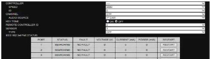
text_image
CONTROLLER SPEED ID CHANNEL AUDIO SOURCE KEY TONE REMOTE CONTROLLER (D) SENSOR TYPE IEEE 500.3W/PE STATUS PORT STATUS FALL/T VOLTAGE (V) CURRENT (mA) POWER (kW) RESTART 1 SSEARCHING NO FAULT 0 0 0 RESTART 2 SHEACHING NO FAULT 0 0 0 RESTART 3 SHEACHING NO FAULT 0 0 0 RESTART7-7-5. Display
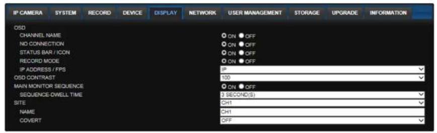
Select the DISPLAY tab to set the DISPLAY conditions.
text_image
IP CAMERA SYSTEM RECORD DEVICE DISPLAY NETWORK USER MANAGEMENT STORAGE UPGRADE INFORMATION OSD CHANNEL NAME NO CONNECTION STATUS BAR / ICON RECORD MODE IP ADDRESS / FPS OSD CONTRAST MAIN MONITOR SEQUENCE SEQUENCE-DWELL TIME SITE NAME COVERT ON OFF ON OFF ON OFF ON OFF IP 100 ON OFF 3 SECOND(S) CH1 CH1 OFFRELOAD APPLY
These settings apply to all channels.
- OSD: Sets whether to display or not date and time as well as channel number on the screen.
- OSD CONTRAST: Adjust the character contrast on the screen.
- MAIN MONITOR SEQUENCE: Setting for automatically switching the displayed video.
• SEQUENCE DWELL TIME: Sets the interval for automatically switching the screens. - SITE: Name, Covert (These settings apply to the specified channel only).
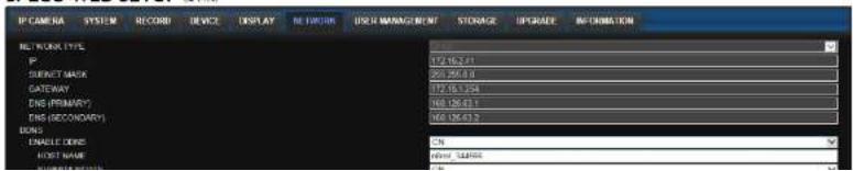
7-7-6. Network
SPECO WEB SETUP
text_image
IP CAMERA SYSTEM RECORD DEVICE DISPLAY NETWORK USE MANAGEMENT STORAGE EPGRADE INFORMATION NETWORK TYPE IP SUBNET MASK GATEWAY END (PRIMARY) END (SECONDARY) BONS ENABLE DONE HOST NAME WINN7-7-7. User Management
Select the USER MANAGEMENT tab to set the DISPLAY conditions.
SPECO WEB SETUP

text_image
PC CAMERA SYSTEM RECORD DEVICE DISPLAY NETWORK USER MANAGEMENT STORAGE UPGRADE INFORMATION AUTHORITY SETUP PASSWORD TITLE ADMIN USER1 USER2 USER3 PASSWORD SETUP PID RECOFF NETWORK USER NAME SETUP NEW USER NAME PASSWORD SETUP CHANGE NEW PASSWORD CONFIGER PASSWORD PLAYBACK AUTHORITY ADDRESS JSON1 ADMIN KEEP ADDRESS 1 2 3 4 5 6 7 8 ADMIN USER1 USER2 USER3 ADDRESS UNIPR1 UNIPR2 UNIPR3 UNIPR1 UNIPR2 UNIPR3 UNIPR1 UNIPR2 UNIPR3 UNIPR1 UNIPR2 UNIPR3 UNIPR1 UNIPR2 UNIPR3 UNIPR1 UNIPR2 UNIPR3 UNIPR1 UNIPR2 UNIPR3 UNIPR1 UNIPR3 UNIPR1 UNIPR2 UNIPR3- AUTHORITY SETUP: Select which users have access to each function, password check can be implemented for each function accessed.
- USER NAME SETUP: Select which Username to change
- NEW USER NAME: Input the new username
- PASSWORD SETUP: Select Username to change Password
○ CHANGE: Select whether to KEEP or CHANGE the current password.
- NEW PASSWORD: Input NEW Password if CHANGE was selected.
o CONFIRM PASSWORD: Input NEW Password again to confirm.
- PLAYBACK AUTHORITY: User can select which users have access to which channels.
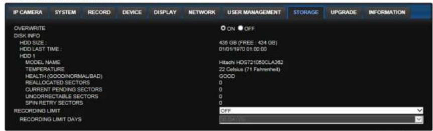
7-7-8. Storage
Select Storage to configure recording settings such as overwriting the hard disk and the setting a storage period for the recording data.
text_image
IP CAMERA SYSTEM RECORD DEVICE DISPLAY NETWORK USER MANAGEMENT STORAGE UPGRADE INFORMATION OVERWRITE ON OFF DISK INFO HDD SIZE : 435 GB (FREE - 434 GB) HDD LAST TIME : 01/01/1970 01:00:00 HDD 1 MODEL NAME Hitachi HDS721080CLA362 TEMPERATURE 22 Celsius (71 Fahrenheit) HEALTH (GOODNORMAL/BAD) GOOD REALLOCATED SECTORS 0 CURRENT PENDING SECTORS 0 UNCORRECTABLE SECTORS 0 SPIN RETRY SECTORS 0 RECORDING LIMIT OFF RECORDING LIMIT DAYSRELOAD APPLY
• OVERWRITE: Select on to continue recording by overwriting when the hard disk becomes full.
- RECORD LIMIT: Sets whether to limit or not the recording data storage period.
7-7-9. Remote Upgrade
SPECO WEB SETUP (ver 1,8,8)
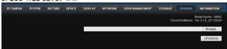
text_image
IP CAMERA SYSTEM RECORD DEVICE DISPLAY NETWORK USER MANAGEMENT STORAGE UPGRADE INFORMATION Model Name: NBNS Current Software: Var 3.7.4_20130524 Browse... UPGRADEShows the current Firmware version installed on NSL.
- Browse: Select BROWSE to locate the firmware file.
7-8. Operation
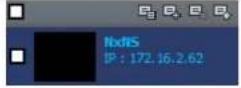
7-8-1. Addition, Delete, and Modify of NSL Sites
7-8-1-1. Addition of Sites
- Click SITE ADDITION button. And then the following window will be displayed as below.

text_image
Site Addition Site info: Site name: Site address: Postnumber: 5445 ID: Password: OK CancelSite Name: Input a name that properly describes a site.
IP Address: Input IP address (Public IP address of a router that NS is connected.) or Domain name
- Port Number: Default Port Number is "5445".
- ID: Input ID of NS. Default ID is "admin".
- Password: Input network password of NS. Default Password is "1111".
- Click OK button. And then the registered site is added on the directory window.
7-8-1-2. Deleting a Site
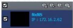
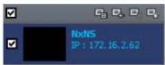
- Select the site/sites to delete from the directory window.
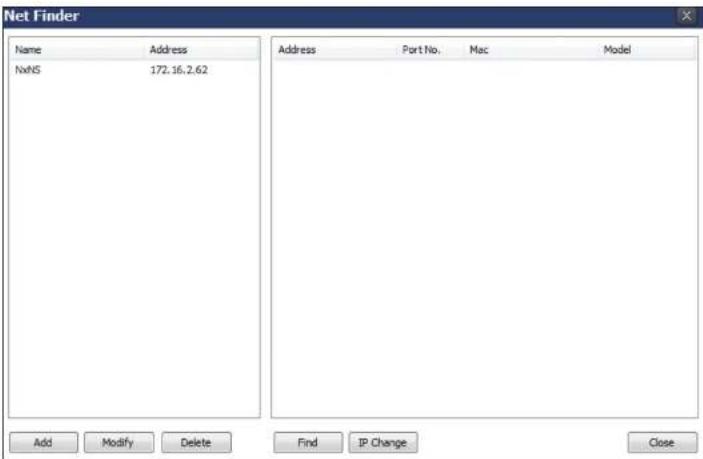
text_image
Net Finder Name Address NxNS 172.16.2.62 Address Port No. Mac Model Add Modify Delete Find IP Change Close- Click MODIFY button. And then the modified information is displayed as below.
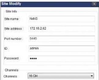
text_image
Site Modify Site Info Site name: NdNS Site address: 172.16.2.62 Port number: 5445 ID: admin Password: **** Channels Channels: 16 CH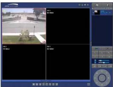
text_image
UN 1 UN 2 UN 3 UN 47-8-2-2. Disconnect
- Select site/sites to disconnect from the directory window.
- Click DISCONNECT button, and then selected site/sites disconnected.
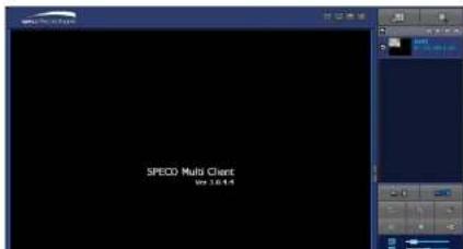
text_image
SPECO Multi Client View 7.0.1.4- Click CAPTURE button. And then a Capture window will be displayed as below.
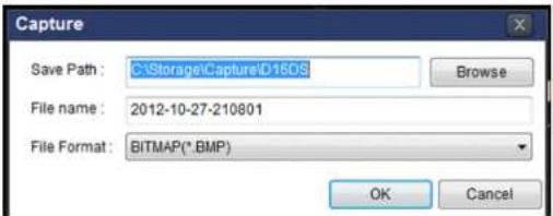
text_image
Capture Save Path: C:\Storage\Capture\D16DS File name: 2012-10-27-210801 File Format: BITMAP(*.BMP) Browse OK Cancel- Set Save Path, File Name, and File Format. And then click OK button.
- Still image is saved as set in Capture window.
7-8-4. Recording Video on Local PC During Live
- Click SETUP button. And then a setup window will be displayed as below.
- Select Record and set the values.

text_image
Setup General Event Event search Record Clack Display About Record Condition Always Event AutoRecord Event Motion Alarm Duration: 6 Sec Channel Site: Site 1 All site All NO CH 1 Channel 1 2 Channel 2 3 Channel 3 4 Channel 4 5 Channel 5 6 Channel 6- Click RECORD ON button. And the color of button is changed.
- Live video data is recorded as set in Record and Disk setup. These video data can be searched and play-backed with Local Playback.
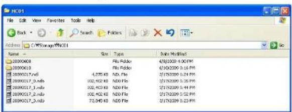
text_image
HC01 File Edit View Favorites Tools Help Back Search Folders Address C:\Storage\HCO1 Name Size Type Bio's Modified 20000608 Filo Folder 6/8/2009 4:00 PM 20000610 Filo Folder 6/10/2009 3:16 PM 2000017.ind 4,275 KB NDO File 3/19/2009 5:24 PM 2000017.inds 102,402 KB NDO File 3/19/2009 5:25 PM 2000017.inds 102,403 KB NDO File 3/19/2009 5:44 PM 2000017.inds 102,402 KB NDO File 3/19/2009 5:52 PM 2000017.inds 73,845 KB NDO File 3/19/2009 5:23 PM7-8-5. Local Playback and Remote Playback
7-8-5-1. Playback of Recorded Video on a Local PC
- Click LOCAL PLAYBACK. And then Playback Window will be displayed over the Live Window.
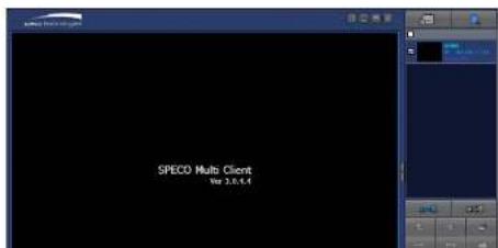
text_image
SPECO Multi Client Vol 3.0.5.4
text_image
Video editing software interface showing a highway scene with multiple video thumbnails and timeline controls- Use the mouse scroll to digitally zoom in and out from a single channel display.
7-8-5-2. Playback of Recorded Video on Remote NSL
- Click REMOTE PLAYBACK. And then Playback Window will be displayed over the Live
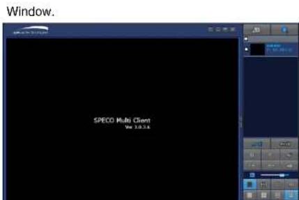
text_image
Window. SPECO Multi Client Rev 3.0.5.6
text_image
Screenshot of a video editing software interface showing a rural road scene with a ruler and control panel at the bottom.7-8-6. AVI Backup during Playback
You can back up the recorded videos in AVI format during playback.
- Double-click the target channel to backup.
- Select the beginning time by using the search calendar and timeline scale bar.

text_image
2011 Apr S M T W T F S 1 2 3 4 5 6 7 8 9 10 11 12 13 14 15 16 17 18 19 20 21 22 23 24 25 26 27 28 29 30 0 2 4 6 8 10 12 14 16 18 20 22 24- Click EZCOPY START button on the timeline scale to select the beginning point of the backup.

text_image
0 10 20 30 40 50 60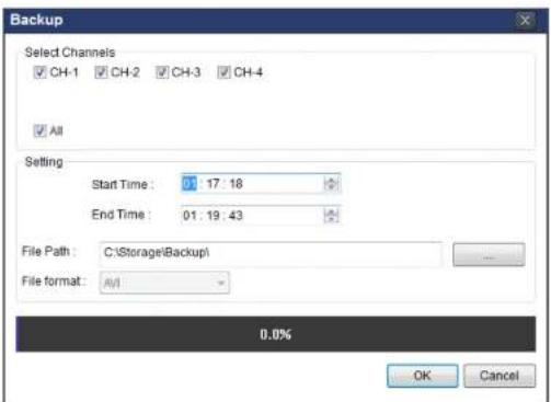
text_image
Backup Select Channels CH-1 CH-2 CH-3 CH-4 All Setting Start Time: 01:17:18 End Time: 01:19:43 File Path: C:\Storage\Backup\ File format: A/I 0.0% OK Cancel- You can also set the beginning time and ending time on this window. After selecting a channel for backup, click the OK button. The backup will begin.
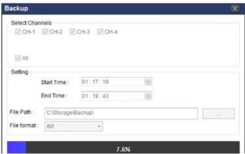
text_image
Backup Select Channels CH-1 CH-2 CH-3 CH-4 All Setting Start Time: 01:17:18 End Time: 01:19:43 File Path: C:\Storage\Backup\ File format: A/I 7.6%8. Network Access Using the Web-Browser Viewer
The NS provides a live remote monitoring feature by web-browser viewer. (NOTE: Web-Browser is only available for Internet Explorer)
- Check the IP address of the NS from SETUP>SYSTEM>DESCRIPTION>IP ADDRESS or
- Input the IP address or Domain name address that you pre-registered.

text_image
Address http://172.16.1.52 Go- Click this bar. Then the dialog box is displayed.

- Click "Install" to download and install the ActiveX control.
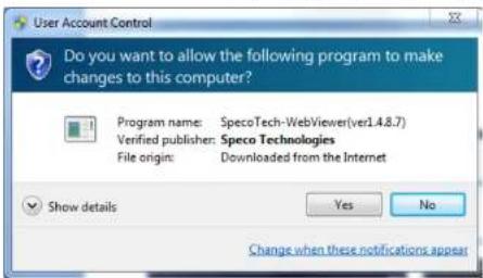
text_image
User Account Control Do you want to allow the following program to make changes to this computer? Program name: SpecoTech-WebViewer(ver1.4.8.7) Verified publisher: Speco Technologies File origin: Downloaded from the Internet Show details Yes No Change when these notifications appear- The Web Browser Viewer will be displayed as below after the ActiveX installation

text_image
Correct Live Next 1 2019-05-31 17:23:50 space technology
text_image
Connect Connect to remote system. IP Address : Port No : 5445 ID : Password : OK Cancel- Site Name: Input a name that properly describes a site.
- IP Address: Input IP address (Public IP address of a router that NS is connected.) or Domain name
• Port Number: Default Port Number is "5445".
• ID: Input ID of NS. Default ID is "admin". -
Password: Input network password of NS. Default Password is "1111".
-
Then the cameras connected to the NS are displayed on the screen.
-
Use mouse scroll to digitally zoom in and out from a single channel display.
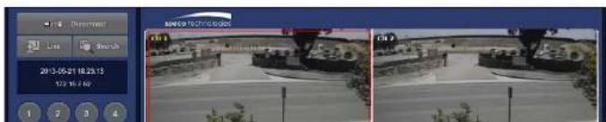
text_image
2013-05-21 18:23:15 172 16:40 SPC9 Technologies 1 2 3 49. Network Access Using the Smart Phone Viewer

Notice
Data Usage applied without Wi-Fi connection. Please check with your Phone Carrier.
9-1. App Viewer for iPhone
- Enter the Apple iTunes Store.

- Search "Speco Player" in the App Store.

Notice
SPECO Player is for the NS, NSL, VS, HS, DS, RS and HD series DVRs. SPECO VIEWER is not compatible with the T Series DVR's (TH, TN or TL) or the PC Series
9-1-1. Live
- Open the installed "Speco Player" App and click button to add a remote device.
- Enter the site name, IP or DDNS address, Network Port number (default 5445), ID(default admin) and Password (default 1111). Then, click "Save" buon.
Edit
Device List
+

- The app will display the selected channel(s). Double tap the channel screen to switch 1 channel display to 4, 8, 10, 16 channels split display depending on the DVR.

text_image
< N16NSF VE 03-10-14 03:47:06 N16SF LIVE 03-10-14 03:47:27 N16SF N16NSF N16NSF N16NSF N16NSF N16NSF N16NSF N16NSF N16NSF N16NSF N16NSF N16NSF N16NSF N16NSF N16NSF N16NSF N16NSF N16NSF N18NSF N18NSF N18NSF N18NSF N18NSF N18NSF N18NSF N18NSF N18NSF N18NSF N18NSF N18NSF N18NSF N18NSF N18NSF N18NSF N18NSF PFS 57 FPS 57- To select the display mode(1, 4, 9, 10 or 16 split display), tap the arrow menus buon
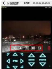
text_image
N16NSF LIVE 03-10-14 03:47:26 LDC 5 FPG 31 1 4 9 10 16 PPTS DOWN FREE9-1-2.PTZ Control
To control the PTZ funcons of the camera, tap the menu buon. Then PTZ menu icons will display. Using the PTZ icon on the screen, control PTZF control.
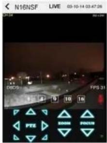
text_image
N16NSF LIVE 03-10-14 03:47:06 DEC 25 FIPS 31 14 0 10 10 PFE DOWN FREE9-1-3. Playback
- Select Mode as 'Playback' 📄 and click 'CONNECT' buon. Then select Date & Time and click PLAY buon.
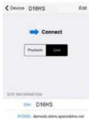
text_image
Device D16HS Edit Connect Playback Size SITE INFORMATION Site D16HS IFONE: demede.dlms.specodlms.net
and click 'CONNECT' buon.
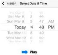
text_image
N18NSF Select Date & Time Sun Mar 9 3 47 AM Today 4 48 PM Tue Mar 11 5 49 Wed Mar 12 6 50 Thu Mar 13 7 37 Play
9-2. App Viewer for Android Phone
- Enter the Android Market.

- Search "Speco Player" in the Android Market and install the "Speco Player" app.

Notice
SPECO Player is for the NS, NSL, DS, RS, WRS and HD series. SPECO VIEWER is not compatible with the T Series NS's (TH, TN or TL) or the PC Series.
9-2-1. Live
- Open the installed "Speco Player" App and select the Live Preview. Then click the menu buon of the phone to add a remote device.
- Select the registered device and select LIVE VIEW and select up to 4 channels or ALL CHANNELS to monitor. Then click START buon.

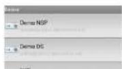


natural_image
Interior view of a room with a large wall clock and equipment (no visible text or symbols)9-2-2. Playback
- Select the registered device and select PLAYBACK and select up to 4 channels or ALL CHANNELS to search. Then click START button. As soon as send the date and me to search, the app will start the playback.
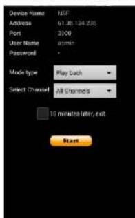
text_image
Device Name: USB Address: 61.38.124.235 Port: 3000 User Name: admin Password: Mode type: Play Back Select Channel: All Channels 10 minutes later, exit Start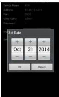
text_image
Set Date Oct 31 2014 OK Cancel
text_image
Set Time 1 50 PM OK Cancel9-2-3.PTZ Control
To control the PTZ funcon of the camera, tap the channel screen, then the channel name will be highlighted in Yellow. Using the PTZ menu icons on the screen, control PTZF.

text_image
H: 20 RGB RGB RGB RGB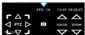
APPENDIX: Network Connection - LAN
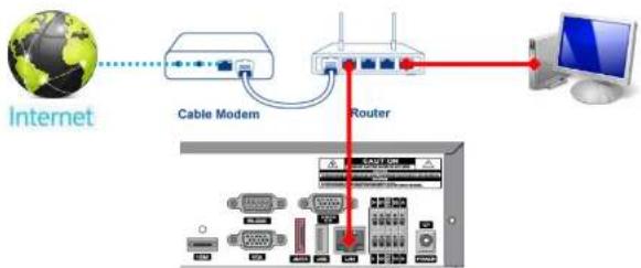
flowchart
graph TD
    A["Internet"] --> B["Cable Modem"]
    B --> C["Router"]
    C --> D["Computer"]
    C --> E["Mobile Device"]
    style A fill:#f9f,stroke:#333
    style D fill:#ccf,stroke:#333
    style E fill:#cfc,stroke:#333
- Install the network client software from the supplied CD.

text_image
SPECO Multi Client Ver 3.1.2.5
text_image
Site Addition Site Info Site name: Site address: Port number: 5445 ID: Password: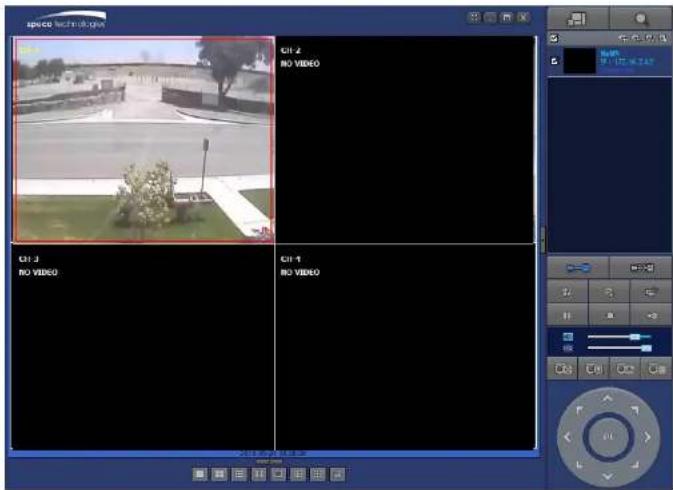
text_image
space technology CJ-1 2 NO VIDEO CJ-3 NO VIDEO CJ-4 NO VIDEOAPPENDIX: Network Connection – Internet and DDNS
Dynamic Domain Name System (DDNS) allows a domain name to be constantly synchronized with a dynamic IP address. A current dynamic IP address is being associated with a static domain name.
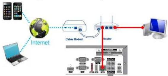
flowchart
graph TD
    A["Mobile Phone"] --> B["Internet"]
    C["Laptop"] --> B
    B --> D["Cable Modem"]
    D --> E["Router"]
    E --> F["Computer"]
    style B fill:#f9f,stroke:#333
    style E fill:#ccf,stroke:#333
- Go to SETUP>NETWORK>DDNS and set the DDNS SERVER to ON.
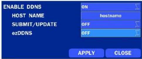
text_image
ENABLE DDNS HOST NAME SUBMIT/UPDATE ezDDNS ON hostname OFF OFF APPLY CLOSEIf you set ezDDNS to ON, the host name is automatically generated and registered.
-
Go to SETUP>NETWORK>DDNS>HOST NAME. Manually enter a domain name using the virtual keyboard and click ENTER button.
-
When DDNS setting is done, click the APPLY button. Otherwise DDNS setting will not be applied.
- When you exit SETUP menu, DDNS NOTIFY window will pop up.

text_image
DDNS NOTIFY : HOST NAME : n8ns_ff1c5 STATUS : SUCCESS OK DDNS NOTIFY : HOST NAME : hostname STATUS : ALREADY REGISTERED OK- DDNS registration status can be checked from SYSTEM INFORMATION or SETUP>SYSTEM>DESCRIPTION>DDNS STATUS
- Check the NETWORK PORT (Default: 5445), WEB PORT (Default: 80), and the IP Address of the NS from SETUP>NETWORK.

text_image
NETWORK NETWORK TYPE IP 172.16.2.41 SUBNET MASK 255.255.0.0 GATEWAY 172.16.1.254 DNS (PRIMARY) 168.126.63.1 DNS (SECONDARY) 168.126.63.2 DDNS # NETWORK PORT 5445 NETWORK AUDIO PORT 5446 WEB PORT 80- Run the network client software.

text_image
SPECO Multi Client Ver 3.1.2.5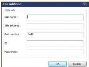
text_image
Site Addition Site Info Site name: Site address: Portnumber: 5445 Password: OK Cancel-
Input Site Name, Site Address (IP address), Port No., and Password on the connect window.
-
Site Name: Input a name that properly describes a site.
• IP Address: Domain name or Public IP address of a router that NS is connected.
• Port Number: Default Port Number is "5445".
• ID: Input ID of NS. Default ID is "admin". -
Password: Input network password of NS. Default Password is "1111".
-
And select the OK button. Then, press _button after checking the left check box.