H6HRL - Security Camera Speco Technologies - Free user manual and instructions
Find the device manual for free H6HRL Speco Technologies in PDF.

User questions about H6HRL Speco Technologies
0 question about this device. Answer the ones you know or ask your own.
Ask a new question about this device
Download the instructions for your Security Camera in PDF format for free! Find your manual H6HRL - Speco Technologies and take your electronic device back in hand. On this page are published all the documents necessary for the use of your device. H6HRL by Speco Technologies.
USER MANUAL H6HRL Speco Technologies
HRL (6/16/24 Channel DVR) User Manual

natural_image
Exterior view of a black electronic device labeled 'specio technology' with control buttons (no readable text beyond branding)H6HRL 6 Channel Hybrid Digital Video Recorder
4 Configurable Hybrid Channels (TVI or IP) plus 2 IP Channels
text_image
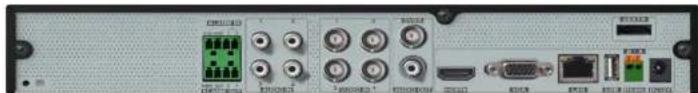
Back panel of a network equipment interface showing ports, connectors, and labels in ChineseH16HRL 16 Channel Hybrid Digital Video Recorder
Notes
- Please read this user manual carefully to ensure that you can use the device correctly and safely.
• The contents of this manual are subject to change without noce. - Do not install this device near any heat sources such as radiators, heat registers, stoves or other devices that produce heat.
- Do not install this device near water. Clean only with a dry cloth.
- Do not block any venlaon openings and ensure proper venlaon around the machine.
- Do not power o the device at normal recording condition.
- This machine is for Indoor use only. Do not expose the machine in rain or moist environment. In case any solid or liquid get inside the machine's case, please turn a the device immediately and get it checked by a qualified technician.
- Do not aempt to repair this device yourself.
Contents
1 Introducon....1
1.1 Welcome 1
1.2 Features.... 1
1.3 Front Panel Descripons 4
1.4 Rear Panel Descripons....4
1.5 Connecons....4
2 Basic Operaon Guide ....5
2.1 Startup & Shutdown 5
2.1.1 Startup....5
2.1.2 Shutdown 5
2.2 Remote Control 5
2.3 Mouse Control 6
2.4 Text-input Instrucon 6
2.5 Common Buon Operaon 7
3 EZ Setup & Main Interface 8
3.1 EZ Setup 8
3.2 Main Interface 12
3.2.1 Main Interface Introducon 12
3.2.2 Setup Panel 14
3.2.3 Main Funcons....15
4 Camera Management 17
Notes& Contents
DVR User Manual
5.3.2 Image Sengs 25
5.3.3 Mask Setngs 25
5.3.4 Water Mark Sengs....25
5.3.5 Image Adjustment 26
6 PTZ 29
6.1 PTZ Control Interface Introducon 29
6.2 Preset Seng 32
6.3 Cruise Setting 33
7 Record& Disk Management 35
7.1 Record Conguraon....35
7.1.1 Mode Conguraon 35
7.1.2 Advanced Conguraon 36
7.2 Encode Parameters Setting 37
7.3 Schedule Seng 38
7.3.1 Add Schedule.... 38
7.3.2 Record Schedule Conguraon 40
7.4 Record Mode 40
7.4.1 Manual Recording 40
7.4.2 Timing Recording....40
7.4.3 Moon Based Recording 41
7.4.4 Sensor Based Recording 41
7.4.5 Analycs Recording 41
7 C Disk 41
Notes& Contents
DVR User Manual
9 Alarm Management....53
9.1 Sensor Alarm 53
9.2 Moon Alarm 54
9.2.1 Moon Conguraon 54
9.2.2 Moon Alarm Handling Conguraon 54
9.3 Smart Event 55
9.3.1 Object Detecon 55
9.3.2 Tampering....56
9.3.3 Tripwire....57
9.3.4 Intrusion Detecon....58
9.4 Excepon Alarm 59
9.4.1 IPC Oline Settings 59
9.4.2 Video Loss Sengs 59
9.4.3 Warning Handling Sengs 60
9.5 Alarm Event Nocaon 60
9.5.1 Alarm-out 60
9.5.2 E-mail....61
9.5.3 Display 61
9.5.4 Buzzer 61
9.5.5 Push Message 62
9.5.6 Alarm Server....62
Notes& Contents
DVR User Manual
11 Device Management....70
11.1 Network Conguraon....70
11.1.1 TCP/IP Conguraon 70
11.1.2 Port Conguraon 70
11.1.3 PPPoE Conguraon 72
11.1.4 DDNS Conguraon....72
11.1.5 E-mail Conguraon 72
11.1.6 UPnP Conguraon 73
11.1.7 802.1X 74
11.1.8 NAT Conguraon 74
11.1.9 View Network Status 74
11.2 Basic Conguraon....75
11.2.1 General Conguraon 75
11.2.2 Date and Time Conguraon....75
11.2.3 Recorder OSD Settings....76
11.3 Factory Default 76
11.4 Device Soware Upgrade 75
11.5 Backup and Restore....77
11.6 Restart Automacally 77
11.7 View Log 78
11.8 View System Informaon 78
12 Remote Surveillance....79
12.1 Mobile Client Currillars 70
1 Introducon
1.1 Welcome
Thank you for purchasing this DVR.
If technical assistance is needed, please contact Speco Technologies Technical Support.
Phone: 1-800-645-5516 opon 3
Email: techsupport@specotech.com
1.2 Features
Basic Funcons
● Supports network device access including IP camera/dome and the Onvif IP cameras
● The DVR supports the H.265 and H.264 IP cameras
● Supports standard ONVIF protocol
● Supports dual stream recording of each camera
● Supports IP cameras to be added quickly or manually
● Supports collective or individual conguraon of the cameras' OSD, video parameters, mask, moon and so on
● Supports a maximum of 8 user permission groups including Administrator, Advanced and Common which are the default permission groups of the system
- Supports a maximum of 16 users to be created, mulple web client login by using one username at the same me and the user's permission control to be enabled or disabled
- Supports mulple web client's login at the same me
Live View
Introducon
DVR User Manual
● Supports any area of the image to be zoomed in to a maximum of 16 mes of the current size
● Supports image and lens adjustment (only available for some cameras)
● Supports quick camera adding in the camera window of the live view interface
Disk Management
● H16HRL/H24HRL supports 2 SATA HDDs
● H16HRL supports 1 SATA HDD
● Supports 1 e-SATA HDD
● Each SATA interface of the DVR supports the HDDs with max 14TB storage capacity
● Supports disk group conguraon and management and each camera can be added into dierent disk groups with dierent storage capacity
● Supports disk informaon and disk working status viewing
● Supports formang disks in batch
Record Conguraon
● Supports main stream and sub stream recording at the same me and collective or individual conguraon of the record stream
● Supports manual and auto record modes
● Supports schedule recording, sensor alarm recording and moon detecon recording, etc
● Supports schedule recording and event recording seng with different record streams
● Supports record schedule seng and recycle recording
● Supports pre recording and delay recording conguraon of the event recording
Record Playback
● Supports me scale operaon in quick playback and the playback date and me can be set randomly by scrolling the mouse; the me interval of the me scale can be zoomed
● Supports record searching by me slice/me/event/tag
● Supports me view and camera view in searching by EZ mode
Introducon
DVR User Manual
Alarm Management
● Supports alarm schedule seng
● Supports enabling or disabling of the moon detecon, external sensor alarm input, intelligence alarm and excepon alarms including IP address conict alarm, disk IO error alarm, disk full alarm, no disk alarm, illegal access alarm, network disconnecon alarm, IPC oine alarm and so on, alarm trigger conguraon supportable
● Supports IPC oine alarm trigger conguraon of PTZ, snapshot, pop-up video, etc.
● Supports event nocaon modes of alarm-out, pop-up video, pop-up message box, buzzer, e-mail and so on
● The captured images can be aached into the e-mail when alarm linkage is triggered
● Supports alarm status view of alarm-in, alarm-out, moon detecon and excepon alarm
● Supports alarm to be triggered and cleared manually
● Supports system auto reboot when excepon happens
Network Funcons
● Supports TCP/IP and PPPoE, DHCP, DNS, DDNS, UPnP, NTP, SMTP protocol and so on
● Supports allow and block list funcon and the allow and block IP address/IP segment address can be set
● Supports multiple browsers including IE8/9/10/11, Firefox, Opera, Chrome (available only for the versions lower than 45) and Safari in MAC system
● Supports remote achievement, conguraon, import and export of the DVR parameters and other system maintenance operaons including remote upgrading and system restart
● Supports remote camera conguraon of the DVR including video parameters, image quality and so on
● Supports remote search, playback and export of the DVR
● Supports manual alarm to be triggered and cleared remotely
● The motorized zoom camera can be adjusted through web client (Supports zoom In/out, but one key focus is not currently supported)
● Supports NAT funcon and QR Code scanning by mobile phone and Tablet
● Supports mobile surveillance by phones or Tablets with IOS or Android OS
Introducon
DVR User Manual
1.3 Front Panel Descripons
The following descripons are for reference only.
| Name | Descripons |
| RTC | When recording, the light is blue |
| Net | When access to network, the light is blue |
| Power | Power indicator, when connoccon, the light is blue |
1.4 Rear Panel Descripons
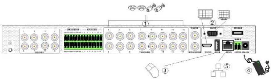
To quickly get started, connect the following to your recorder in the following order, please refer to the following gure (H24HRL shown for reference).
text_image
Diagram of a network device rack with labeled ports and connectors, including drive, port, and cable connections.- Connect analog cameras to the video input ports (BNC) of the recorder.
- Connect a monitor to the recorder via VGA or HDMI cable (not included).
- Connect the included onal mouse into any USB port of the recorder
2 Basic Operaon Guide
2.1 Startup & Shutdown
Please make sure all the connexons are done properly before you power on the unit. Proper startup and shutdown are crucial to extending the life of your device.
2.1.1 Startup
① Connect the output display device to the VGA/HDMI interface of the DVR.
② Connect with the mouse and power. The device will boot and the power LED would turn blue.
⑧ EZ setup window will pop up (you should select the display language the rst me you use the DVR). Refer to 3.1 EZ Setup for details.
2.1.2 Shutdown
You can power o the device by using remote control or mouse.
By remote control:
① Press Power buon. This will take you to a shutdown window. The unit will power o aer a while by clicking the "OK" buon.
② Disconnect the power.
By mouse:
① Click Start→Shutdown to pop up the Shutdown window. Select "Shutdown" in the window. The unit will power o aer a while by clicking the "OK" buon.
② Disconnect the power.
2.2 Remote Control
① It uses two AAA size baeries.
② Open the baerv cover of the remote control.

text_image
REC 1 2 3 4 5 6 7 8 9 ←→ 0 Fn1 Multi Next SEQ Audio SPOY ENTER Menu Exit + IRIS+ Focus P.T.Z + - IRIS- Precat Cruise Wake Light Track Clear Fa2 INFO ■ Break Search ◀◀ ▶ Cut Backup ◀◀ Zoom Pop| Buon | Funcon |
| Switch o - to stop the device | |
| Record Buon | To start recording |
| -/- /0-9 | Input number or choose camera |
| Fn1 Buon | Unavailable temporarily |
| Mul Buon | To choose mul screen display mode |
| Next Buon | To switch the live image |
| SFO | To go to sequence view mode |
| Audio | To enable audio output in live mode |
| Switch | No funcon temporarily |
| Direcon buon | To move cursor in setup or pan/ile PTZ |
| Enter Buon | To conrm the choice or setup |
| Menu Buon | To go to menu |
| Exit Buon | To exit the current interface |
| Focus/IRIS/Zoom/PTZ | To control PTZ camera |
| Preset Buon | To enter into preset seng in PTZ mode |
| Cruise Buon | To go to cruise seng in PTZ mode |
| Track Buon | No track funcon temporarily |
| Wiper Buon | No funcon temporarily |
| Light Buon | No funcon temporarily |
| Clear Buon | No funcon temporarily |
| Fn2 Buon | No funcon temporarily |
| Info Buon | Get informaon about the device |
| To control playback. Play (Pause)/Stop/Previous Frame/Next Frame/Speed Down/Speed Up | |
| Snap Buon | To take snapshots manually |
| Search Buon | To go to search mode |
| Cut Buon | No funcon temporarily |
| Backup Buon | To go to backup mode |
| Zoom Buon | To zoom in the images |
| PIP Buon | Not save |

text_image
1 2 3 4 5 6 DEL 7 8 9 0 . 1 2 3 4 5 6 7 8 9 0 q w e r t y u l e p a s d f g h j k l y z a c v b n m EN/CN @ #?!The system includes two input boxes. Refer to the above pictures. The le box is the number input box and the right box is the input box which provides inputs of numbers, letters and punctuation characters. The introducons of keys on the input boxes are shown below.
| Buon | Meaning | Buon | Meaning |
| Backspace key | Switch key of punctuation character | ||
| Delete Key | Enter key | ||
| Switch key between upper and lower locr | Space key | ||
| Switch key of language | |||
2.5 Common Buon Operaon
| Buon | Meaning |
| Click it to show the menu list. | |
| Click it to change the sequence of the list. | |
| Click it to change the camera displaying mode. | |
| Click it to close the current interface. | |
| Click it to go to the earliest date of camera recording. | |
| Click it to go to the latest date of camera recording. |
3 EZ Setup & Main Interface
3.1 EZ Setup
The disk icons will be shown on the top of the startup interface. You can view the number and status of each disk quickly and conveniently through these icons (no disk; unavailable disk; RW available disk).
You must congregate the wizard if you start the DVR for the rst me (or click "Skip" to cancel the EZ Setup next me).
The rst me you start up your DVR, you shall choose the language and locality as needed. Aer that, you shall congure date and me.
System Time: Set the me and date format of the system
DST: Toggle Daylight Saving Time On or O
Time format: Choose between 24-hour mode and 12-hour mode.
NTP: Specify an NTP server to synchronize the me (oponal).

text_image
EZ Setup Time Zone GMT-12 West of the International Timeline System Time 03/24/2018 03:02:41 PM Date Format Month-Day/Year Time Format 12 Hour DST 17 Synchronous Manual NTP Server New Subtotal Long Video Format Preview NextClick "Next" to connue.
EZ Setup & Main Interface
DVR User Manual
Enable paern lock and click "Edit" to set the paern lock.

Click "Edit Security Queson" to set quesons and answers for password security of admin. If you forget the password, please refer to Q4 in Appendix A FAQ for details.
Click "Next" to connue.
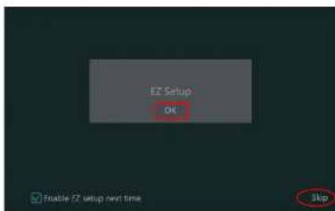
Aer you log In, you will see an EZ setup Interface as shown below.
text_image
EZ Setup OK Flexible EZ setup next time SkipEZ Setup & Main Interface
DVR User Manual
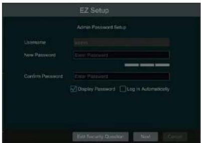
text_image
EZ Setup Admin Password Setup Username: New Password: Confirm Password: Enter Password: Display Password Log In Automatically Edit Security Preview Next CancelClick "Next" to connue or click "Cancel" to exit the wizard.
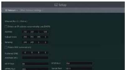
② Network Sengs. Select the network work paern as required. Check "Obtain an IP address automacally" and "Obtain DNS automacally" to get the IP address and DNS automacally (the DHCP funcon of the router in the same LAN should also be enabled), or manually enter them. Enter the HTTP port, RTSP port and Server port (please see 12.1.2 Port Conguraon for details). Click "Next" to connue.
text_image
EZ Setup Ethernet Port 1 (Binary) Address and IP address automaticity (low CMPS) Address: 100 200 300 Subnet mask: 205 255 355 Grammar: 255 400 500 Global XML automaticity Fidelity DNS Automatic DNS FTP Port: 20 FTP Port: 411 USB Port: 168 Server Port: 0.01EZ Setup & Main Interface
DVR User Manual

text_image
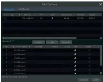
EZ Setup Other Network Settings URL Network Type: 100 200 300 400 500 600 700 800 900 1000 1100 1200 1300 1400 1500 1600 1700 1800 1900 2000 2100 2200 2300 2400 2500 2600 2700 2800 2900 3000 3100 3200 3300 3400 3500 3600 3700 3800 3900 4000 4100 4200 4300 4400 4500 4600 4700 4800 4900 5000 5100 5200 5300 5400 5500 5600 5700 5800 5900 6000 6100 6200 6300 6400 6500 6600 6700 6800 6900 7000 7100 7200 7300 7400 7500 7600 7700 7800 7900 8000 8100 8200 8300 8400 8500 8600 8700 8800 8900 9000 9100 9200 9300 9400 9500 9600 9700 9800 9900 100④ Add Camera. To add cameras from the LAN, make sure all cameras are set to DHCP. Click "Refresh" to refresh the list of online IP cameras which are in the same local network with DVR and then click ✕ to add the searched camera. Click "Add All" to add all the cameras in the list. Click ✗ to delete the added camera. Click "Delete All" to delete all the added cameras.

text_image
EZ Setup IE Design 1 - 0.000000000000000000000000000000000000000000000000000000000000000000000000000000000000000000000000 File Edit View Insert Tools Help Options 1 M16.12.13 2 M16.12.13 3 M16.12.13 4 M16.12.13 5 M16.12.13 6 M16.12.13 7 M16.12.13 8 M16.12.13 9 M16.12.13 10 M16.12.13 11 M16.12.13 12 M16.12.13 13 M16.12.13 14 M16.12.13 15 M16.12.13 16 M16.12.13 17 M16.12.13 18 M16.12.13 19 M16.12.13 20 M16.12.13 21 M16.12.13 22 M16.12.13 23 M16.12.13 24 M16.12.13 25 M16.12.13 26 M16.12.13 27 M16.12.13 28 M16.12.13 29 M16.12.13 30 M16.12.13 31 M16.12.13 32 M16.12.13 33 M16.12.13 34 M16.12.13 35 M16.12.13 36 M16.12.13 37 M16.12.13 38 M16.12.13 39 M16.12.13 40 M16.12.13 41 M16.12.13 42 M16.12.13 43 M16.12.13 44 M16.12.13 45 M16.12.13 46 M16.12.13 47 M16.12.13 48 M16.12.13 49 M16.12.13 50 M16.12.13 51 M16.12.13 52 M16.12.13 53 M16.12.13 54 M16.12.13 55 M16.12.13 56 M16.12.13 57 M16.12.13 58 M16.12.13 59 M16.12.13 60 M16.12.13 61 M16.12.13 62 M16.12.13 63 M16.12.13 64 M16.12.13 65 M16.12.13 66 M16.12.13 67 M16.12.13 68 M16.12.13 69 M16.12.13 70 M 88Mg/88Mg/88Mg/88Mg/88Mg/88Mg/88Mg/88Mg/88Mg/88Mg/88Mg/88Mg/88Mg/88Mg/88Mg/88Mg/88Mg/88Mg/88Mg/88Mg/88Mg 88Mg/88Mg/88Mg/88Mg/88Mg/88Mg/88Mg/88Mg/88Mg/88Mg/88Mg/88Mg/88Mg/88Mg/88Mg/88Mg/88Mg/ 88Mg/ 88Mg/ 88Mg/ 88Mg/ 88Mg/ 88Mg/ 88Mg/ 88Mg/ 88Mg/ 88Mg/ 88Mg/ 88Mg/ 88Mg/ 88Mg/ 88Mg/ 88Mg/ 88M g 88Mg/ 88Mg/ 88Mg/ 88Mg/ 88Mg/ 88Mg/ 88Mg/ 88Mg/ 88Mg/ 88Mg/ 88Mg/ 88Mg/ 88Mg/ 8EZ Setup & Main Interface
DVR User Manual
the camera. You can click "Test" to test the effectiveness of the input informaon. Click "OK" to save the sengs. You can change the IP camera name only when the added camera is online. Click "Next" to connue.
⑤ Disk Sengs. You can view the disk number, disk capacity of the DVR and serial number, R&W status of the disk. Click "Formang" to format the disk. Click "Next" to connue.
⑥ Record Sengs. Two record modes are available: auto and manual.
Auto: Select one auto mode in the interface as shown below and then click "Next" buon to save the settings. Click "Advanced" to self-dene record mode. See 7.1.1 Mode Conguraon for details.

text_image
E2 Setup File Version 1 Edit Settings Help Settings E2 Wizard 1 Color Color Options Solid Color Solid Yellow Solid Black Solid Red Solid Green Solid Black Solid Red Solid Green Solid Black Solid Red Solid Green Solid Black Solid Red Solid Green Solid Black Solid Red Solid Green Solid Black Solid Red Solid Green Solid Black Solid Red Solid Green Solid Black Solid Red Solid Green Solid Black Solid Red Solid Green Solid Black Solid Red Solid Green Solid Black Solid Red Solid Green Solid Black Solid Red Solid GreenManual: Set the "Sensor Record", "Moon Record" and "Schedule Record" of each camera. Click "OK" to save. See 7.1.1 Mode Conguraon for details.

text_image
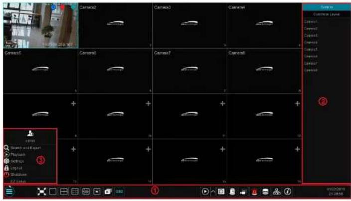
Camera2 Camera3 Camera4 Camera5 Camera6 Camera7 Camera8 Camera9 Camera10 Camera11 Camera12 Camera13 Camera14 Camera15 Camera16 Camera17 Camera18 Camera19 Camera20 Camera21 Camera22 Camera23 Camera24 Camera25 Camera26 Camera27 Camera28 Camera29 Camera30 Camera31 Camera32 Camera33 Camera34 Camera35 Camera36 Camera37 Camera38 Camera39 Camera40 Camera41 Camera42 Camera43 Camera44 Camera45 Camera46 Camera47 Camera48 Camera49 Camera50 Camera51 Camera52 Camera53 Camera54 Camera55 Camera56 Camera57 Camera58 Camera59 Camera60 Camera61 Camera62 Camera63 Camera64 Camera65 Camera66 Camera67 Camera68 Camera69 Camera70 Camera71 Camera72 Camera73 Camera74 Camera75 Camera76 Camera77 Camera78 Camera79 Camera80 Camera81 Camera82 Camera83 Camera84 Camera85 Camera86 Camera87 Camera88 Camera89 Camera90 Camera91 Camera92 Camera93 Camera94 Camera95 Camera96 Camera97 Camera98 Camera99 Camera100The buons in area ① are introduced in the table below.
| Buon | Meaning |
| Start buon. Click it to pop up area 3. | |
| Full screen buon. Click it to show full screen; click it again to exit the full screen. | |
| Screen mode buon. | |
| Sequence buon (see 5.2.2 Quick Sequence View and 5.2.4 Scheme View in Sequence for details). | |
| Click it to enable OSD; click again to disable OSD. | |
| Clickto set the default playback me before strong instant playback (8.1 Instant) |
EZ Setup & Main Interface
DVR User Manual
one camera in the list to preview the camera image in the selected window.
Click "Customize Layout" to view all the display modes in the display mode list (refer to 5.2.1 Display Mode for detail conguraon of the display mode). Double click one display mode in the list to switch to the display mode for previewing.
Introducon of area ③:
| Icon / Buon | Meaning |
| It shows the current login user. | |
| Click to go to record search and export interface, see 8.4 Record Search.Playback & Export for details. | |
| Click to go to playback interface (click on the tool bar at the boom of the live view interface to set the default playback me), see 8.2 Playback Interface.Introducefor details. | |
| Click to pop up the setup panel, see 3.2.2 Setup Panel for details. | |
| Click to log out the system. | |
| Click and then select "Logout", "Reboot" or "Shutdown" in the popup window. | |
| Click to go to the EZ setup. |
3.2.2 Setup Panel
Click Start→Sengs to bring up the setup panel as shown below.

text_image
06/25/2019 1:38:41 06/25/2019 1:38:41 Camera Customize LevelEZ Setup & Main Interface
DVR User Manual
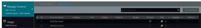
Here we take Camera module as an example. The Camera module provides convenient links such as "Add Camera", "Edit Camera", "Image Sengs", "Moon", "Intelligence Analys" and "PTZ". Click Camera to go to the camera management interface as shown below.
text_image
Manage Camera Add Camera Camera Engine | Add Camera Image G80 Settings 1 2 3 4 5 6 7 8 9 10 11 12 13 14 15 16 17 18 19 20 21 22 23 24 25 26 27 28 29 30 31 32 33 34 35 36 37 38 39 40 41 42 43 44 45 46 47 48 49 50 51 52 53 54 55 56 57 58 59 60 61 62 63 64 65 66 67 68 69 70 71 72 73 74 75 76 77 78 79 80 81 82 83 84 85 86 87 88 89 90 91 92 93 94 95 96 97 98 99 100There are some funcon items on the le side of the camera management interface. Click each Item to go to corresponding interface or window. For instance, click "Add Camera" to pop up the window as shown below.

text_image
Add Camera Name: Add Manual File Edit View Insert Tools Help 1 172.18.26.205 30 8:49:00 SPEED COOPT Source: A/1 Select Adjust Cancel Apply No If Options Name Options Properties Copy Add 1 jxjy.com/1 2 jxjy.com/2 3 jxjy.com/3 4 jxjy.com/4 5 jxjy.com/5 6 jxjy.com/6 7 jxjy.com/7 8 jxjy.com/8 9 jxjy.com/9 10 jxjy.com/10 11 jxjy.com/11 12 jxjy.com/12 13 jxjy.com/13 14 jxjy.com/14 15 jxjy.com/15 16 jxjy.com/16 17 jxjy.com/17 18 jxjy.com/18 19 jxjy.com/19 20 jxjy.com/20 21 jxjy.com/21 22 jxjy.com/22 23 jxjy.com/23 24 jxjy.com/24 25 jxjy.com/25 26 jxjy.com/26 27 jxjy.com/27 28 jxjy.com/28 29 jxjy.com/29 30 jxjy.com/30 31 jxjy.com/31 32 jxjy.com/32 33 jxjy.com/33 34 jxjy.com/34 35 jxjy.com/35 36 jxjy.com/36 37 jxjy.com/37 38 jxjy.com/38 39 jxjy.com/39 40 jxjy.com/40 41 jxjy.com/41 42 jxjy.com/42 43 jxjy.com/43 44 jxjy.com/44 45 jxjy.com/45 46 jxjy.com/46 47 jxjy.com/47 48 jxjy.com/48 49 jxjy.com/49 50 jxjy.com/50 51 jxjy.com/51 52 jxjy.com/52 53 jxjy.com/53 54 jxjy.com/54 55 jxjy.com/55 56 jxjy.com/56 57 jxjy.com/57 58 jxjy.com/58 59 jxjy.com/59 60 jxjy.com/60 61 jxjy.com/61 62 jxjy.com/62 63 jxjy.com/63 64 jxjy.com/64 65 jxjy.com/65 66 jxjy.com/66 67 jxjy.com/67 68 jxjy.com/68 69 jxjy.com/69 70 jxjy.com/70 71 jxjy.com/71 72 jxjy.com/72 73 jxjy.com/73 74 jxjy.com/74 75 jxjy.com/75 76 jxjy.com/76 77 jxjy.com/77 78 jxjy.com/78 79 jxjy.com/79 80 jxjy.com/80 81 jxjy.com/81 82 jxjy.com/82 83 jxjy.com/83 84 jxjy.com/84 85 jxjy.com/85 86 jxjy.com/86 87 jxjy.com/87 88 jxjy.com/88 89 jxjy.com/89 90 jxjy.com/90 91 jxjy.com/91 92 jxjy.com/92 93 jxjy.com/93 94 jxjy.com/94 95 jxjy.com/95 96 jxjy.com/96 97 jxjy.com/97 98 jxjy.com/98 99 jxjy.com/99 100 jxjy.com 100Click the main menus on the top of the camera management interface to go to corresponding interfaces. Refer to the picture below. For instance, you can go to the system setup interface by clicking "System" tag.
EZ Setup & Main Interface
DVR User Manual
Alarm
The module covers the funcons such as Sensor and Moon Alarm Handling and Alarm Out Sengs. Please see Chapter 9 Alarm Management for details.
Disk
The module covers the funcons such as Disk Management, Storage Mode and Disk Information and so on. Please see Chapter 7 Record & Disk Management for details.
Network
The module covers the funcons such as TCP/IP, DDNS, Port, E-mail and Network Status and so on. Please see 11.1 Network Conguraon for details.
Account and Authority
The module covers the funcons such as Account Management (see 10.1 Account Management for details) and Permission Management (see 10.3 Permission Management for details) and so on.
System
The module covers the funcons such as Basic Conguraon (see 11.2 Basic Conguraon for details), Device Informaon (see 11.8 View System Informaon for details), Log Informaon (see 11.7 View Log for details) and Conguraon File Import&Export (see 11.5 Backup and Restore for details) and so on.
4 Camera Management
4.1 Camera Signal
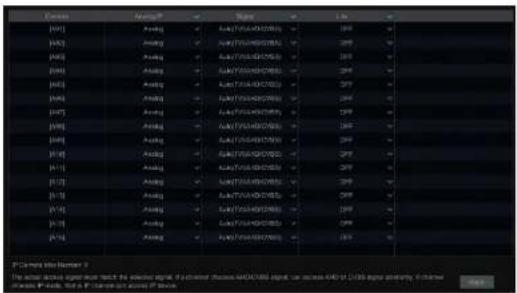
Click Start→Sengs→Camera→Manage Camera→Camera Signal to go to the interface as shown below.
Some models may support analog signal switching to IP signal, which means decreasing (or increasing) the number of analog channels will accordingly increase (or decrease) the number of IP channels.
The DVR device supports hybrid access of TVI, and CVBS high denion cameras. If the TVI high denion camera is accessed to the DVR, you should select TVI/CVBS in the following interface to show the camera image normally; if you select AHD/CVBS, then there will be no image or the image has no color. The default selecon of the camera signal is Auto. If you select Auto, the image of the camera will be shown normally regardless of the camera type.
text_image
C101 A101 A102 A103 A104 A105 A106 A107 A108 A109 A110 A111 A112 A113 A114 A115 A116 A117 A118 A119 A120 A121 A122 A123 A124 A125 A126 A127 A128 A129 A130 A131 A132 A133 A134 A135 A136 A137 A138 A139 A140 A141 A142 A143 A144 A145 A146 A147 A148 A149 A150 A151 A152 A153 A154 A155 A156 A157 A158 A159 A160 A161 A162 A163 A164 A165 A166 A167 A168 A169 A170 A171 A172 A173 A174 A175 A176 A177 A178 A179 A180 A181 A182 A183 A184 A185 A186 A187 A188 A189 A190 A191 A192 A193 A194 A195 A196 A197 A198 A199 A200Note: You can enable "Lite" in the interface if the DVR supports "Lite" recording. It will lower the recording resolution and increase the recording frame rate. Please enable or disable the Lite as needed.
A.2 Add/Edit Camera
Live View Introducon
DVR User Manual
text_image
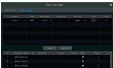
Add Camera Select: Add Normally No. 100 Address: Font: Edit: Subscript size: Project: Name: 1 07/2 16:28:29 30 8.5.9.9 SPECD U2EPX Source: 0/1 Delete Add Save All No. 100 F:\AC\Control F:\AC\Control F:\AC\Control F:\AC\Control F:\AC\Control F:\AC\Control F:\AC\Control Source: Business 32 / 12/06 Advanced Cancel> Quickly Add
Check the cameras and then click "Add" to add cameras. Click to edit the camera's IP address, username and password and so on. Click "Default Password" to set the default username and password of each camera.
text_image
Add Camera Modify Box: Any Options Address: Fast Password: Password Project: Time Balance: 100% Name: Add Camera Name: Active Protocol: Status OK Cancel 1 [p] Control 2 [p] Control 3 [p] ControlLive View Introducon
DVR User Manual
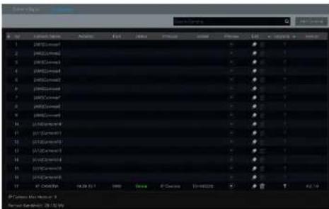
header line and then click "Modify IPC Password" to pop up a window (check the IPCs in the window, set the new password and then click "OK" buon; only the online IPCs' passwords can be modified and a batch of IPCs' passwords can be modified at the same me). Click to upgrade
an online IPC (or click in the "Upgrade" header line and then click "IPC Batch Upgrade" to upgrade a batch of IPCs), select the device which stores the upgrade le in the "Device Name" item of the popup window and the upgrade le in the list(you should select the upgrade IPC model in the window if a batch of IPCs' passwords need to be modified) and then click "Upgrade" button to start upgrading(the IPC will restart automatically aer the upgrade is completed successfully).
text_image
1 2 3 4 5 6 7 8 9 10 11 12 13 14 15 16 17 18 19 20 21 22 23 24 25 26 27 28 29 30 31 32 33 34 35 36 37 38 39 40 41 42 43 44 45 46 47 48 49 50 51 52 53 54 55 56 57 58 59 60 61 62 63 64 65 66 67 68 69 70 71 72 73 74 75 76 77 78 79 80 81 82 83 84 85 86 87 88 89 90 91 92 93 94 95 96 97 98 99 100Live View Introducon
DVR User Manual
5 Live View Introducon
5.1 Live View Interface Introducon
Refer to the interface as shown below, drag one camera in the preview window to another window for camera window exchanging.
The record symbols with dlerent colors in the live view window refer to dlerent record types when recording: green stands for manual record, red stands for sensor based record, yellow stands for moon based record, blue stands for schedule record and cyan stands for intelligence record.

text_image
Camera1 Camera2 Camera3 Camera4 Camera5 Camera6 Camera7 Camera8 Camera9 Camera10 Camera11 Camera12 Camera13 Camera14 Camera15 Camera16 Camera17 Camera18 Camera19 Camera20 Camera21 Camera22 Camera23 Camera24 Camera25 Camera26 Camera27 Camera28 Camera29 Camera30 Camera31 Camera32 Camera33 Camera34 Camera35 Camera36 Camera37 Camera38 Camera39 Camera40 Camera41 Camera42 Camera43 Camera44 Camera45 Camera46 Camera47 Camera48 Camera49 Camera50 Camera51 Camera52 Camera53 Camera54 Camera55 Camera56 Camera57 Camera58 Camera59 Camera60 Camera61 Camera62 Camera63 Camera64 Camera65 Camera66 Camera67 Camera68 Camera69 Camera70 Camera71 Camera72 Camera73 Camera74 Camera75 Camera76 Camera77 Camera78 Camera79 Camera80 Camera81 Camera82 Camera83 Camera84 Camera85 Camera86 Camera87 Camera88 Camera89 Camera90 Camera91 Camera92 Camera93 Camera94 Camera95 Camera96 Camera97 Camera98 Camera99 Camera100Click the preview window to show the tool bar as shown in area ①; right click the preview window to show the menu list. The tool bar and menu list are introduced in the table below.
Live View Introducon
DVR User Manual
image. Click the camera selecon box to select other cameras for amplicaon. Click "Back" to return to the live view interface.
natural_image
Highway traffic scene with multiple lanes and cars, no visible text or symbols5.2 View Mode
5.2.1 Display Mode
Set dierent screen modes and cameras' display sequences as needed and then save the display modes classed by surveillance areas, priories and so on. Refer to the picture below. Double click one display mode in the display mode list to view the live images in this mode.

text_image
Street photo with visible store signboards and interior hallwayLive View Introducon
DVR User Manual
③ Click under the display mode list and then enter the display mode name in the popup window, click the "OK" buon to save the current display mode.
Method Two:
① Click Start→Sengs→System→Basic→Output Settings to go to the interface and then set the screen mode.
② Double click the camera or camera group in the list to add them to the selected window.
Click to save the current display mode (refer to 5.2.4 Scheme View In Sequence for detail conguraons). The display mode will be saved and displayed in the display mode list in the live view interface.
Edit Display Mode
Click "Customize Layout" tab in the live view interface and then select one display mode in the list. Click to edit the display mode name; click to delete the display mode.
5.2.2 Quick Sequence View
You can start quick sequence view if the scheme has not been created. If the scheme has been created, please refer to 5.2.4 Scheme View in Sequence for details.
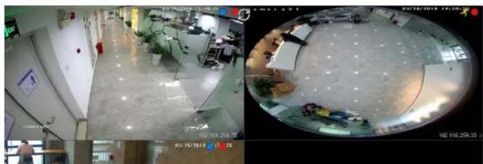
natural_image
Two-panel surveillance camera view showing interior scenes: one with floor plan and equipment, the other with circular overlay of a room with equipment (no visible text or symbols)Live View Introducon
DVR User Manual
5.2.3 Scheme View In Sequence
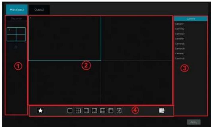
Click Start→Sengs→System→Basic→Output Settings to go to the interface as shown below.
Area ① displays all the sequence schemes; area ② shows the detailed informaon of the scheme; area ③ displays all the cameras and groups; area ④ is the tool bar (clear buon); favorite buon, click it to pop up a window, enter the display mode name in the window and then click "OK" to save the current display mode; other buons are screen mode buons).
text_image
Main Output Cubu2 Sequence ① ② ③ Camera Camera1 Camera2 Camera3 Camera4 Camera5 Camera6 Camera7 Camera8 ★ □ □ □ □ □ ④ ApplyAdd Scheme
Click + In area ① to create a new scheme. Click ✗ on the top right corner of the scheme to delete it.
Live View Introducon
DVR User Manual
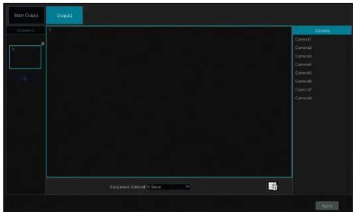
Click + on the le to create a new scheme. Each scheme can only add one analog camera. Select a scheme on the le and then double click or drag a camera on the right to the scheme window in the middle of the interface. Aer nishing the sengs of all the schemes, select the sequence interval and click "Apply" to start playing the schemes in sequence in output 2.
text_image
Main Output1 Output2 Camera Camera1 Camera2 Camera3 Camera4 Camera5 Camera6 Camera7 Camera8 Sequence Interval 0 Secs Apply...5.3 Image Conguraon
5.3.1 OSD Sengs
Click Start→Sengs→Camera→Image→OSD Sengs to go to the Interface as shown below. Select the camera, enter the camera name (or double click the camera name in the camera list to change the camera name), enable or disable the name and me OSDs (if enabled, drag the red name and me OSDs directly in the image view area to change the OSDs' display posion) and select the date, me format and color. Click "Apply" to
Live View Introducon
DVR User Manual
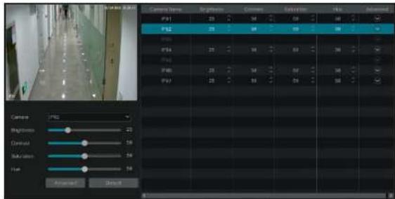
5.3.2 Image Sengs
Click Start→Settings→Camera→Image→Image Settings to go to the following interface. Select the camera and then set the brightness, contrast, saturation and hue of the camera. Click "Advanced" button or in the camera list on the right side of the interface to pop up "Image Adjust" interface and then set the relevant setting items. Please refer to 5.4.5 Image Adjustment for detailed introductions of these items.
You can click "Default" to restore the image sengs to the default factory sengs.
text_image
Camera Name: FP1 FP2 FP3 FP4 FP5 FP6 FP7 Camera Brightness: Contrast: Noise tone: Wave: Approxed 1 Default Select Time 00:00:00 00:00:00 00:00:00 00:00:00 00:00:00 00:00:00 00:00:00 00:00:00 00:00:00 00:00:00 00:00:00 00:00:005.3.3 Mask Sengs
Some areas of the image can be masked for privacy. Up to four mask areas can be set for each camera. Click Start→Setings→Camera→Image→Mask Sengs to go to the interface as shown below. Select the camera and enable the mask. Click "Draw" buon and then drag the mouse on the image area to set the mask area; click "Delete" buon to delete the mask areas; click "Apply" to save the sengs.

text_image
Camera Name Mask Color Camera1 ON Black Camera2 OFF Black Camera3 OFF BlackLive View Introducon
DVR User Manual

text_image
Camera Name Water Mark Information Camera1 ON XXXXX Camera2 OFF Camera3 OFF Camera4 OFF Camera Camera1 Water Mark ON Information XXXXX Apply5.3.5 Image Adjustment
Go to the live view interface and then click buon on the tool bar under the camera window to go to the image adjustment interface.

text_image
Screenshot of a highway photo editing interface showing video editing controls and channel settingsLive View Introducon
DVR User Manual
| Parameter | Meaning |
| Sharpen | It relates to the resolution level of the image plane and the sharpness level of the image edge. |
| Wide Dynamic | The wide dynamic range (WDR) funcon helps the camera provide clear images even unde back light circumstances. When there are both very bright and very dark areas simultaneously in the aid of view, WDR balances the brightness level of the whole image and provide clear images with details. |
| Denoise | Adopt the noise reduction technology to decrease the noise and make the image more thorough. Increasing the value will make the noise reduction effect beer but it will reduce the image resolution. |
| White Balance | White balance is the white rendition function of the camera to adjust the color temperature according to the environment automatically. |
| BLC | HLC: lowers the brightness of the entire image by suppressing the brightness of the image's bright area and reducing the size of the halo area.BLC: if enabled, the auto exposure will octave according to the scene so that the object of the image in the darked area will be seen clearly. |
| Image Mirror | Reverse the current video image right and lc. |
| Image Flip | Turn the current video image upside down. |
Lens Control
Select the camera and then click "Lens Control" to go to lens control tab. Click or to adjust the zoom and focus parameters of the camera's lens. Click "Save" to save the sengs.

text_image
Camera Camera1 Image Adjust: Auto Control +Zoom + Focus Mode: Manual Mode +Focus +Line Key Focus Switch the Back Mode to cover the right side of the road. Copyright mode switch autofocus.| Buon/Parameter | Meaning |
| Day/night mode switch autofocus | If checked, the lens will focus automatically when the camera is switching day/night mode. |
| Time Interval | It is the me interval when camera lens is auto-focusing. The interval can be set in the drop-down list. |
Note: if the lens of the camera connected to the DVR is xed, the lens control funcon is unavailable.
6 PTZ
6.1 PTZ Control Interface Introducon
You can control the IP dome or PTZ which connects to the IP camera for PTZ control.
Click on the tool bar at the boom of the live view window to go to the PTZ control interface as shown below. You can select another IP dome or PTZ which connects to the IP camera on the top right of the interface for PTZ control.
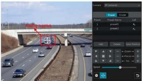
text_image
Analog Joystick Camera IP Camera1 Preset Cruise Preset Preset Name Call 1 preset1 A 2 preset2 Add Delete Save Position Zoom- Focus- Ins SpeedIntroducons of the buons on the boom right of the Interface:

farther you drag the analog joysck from the middle of the image, the faster the dome or PTZ rotates. The dome or PTZ will stop rotang when you stop dragging the analog joysck.
3D Control
Click the camera image on any area and then the image will be centered on the clicked point.
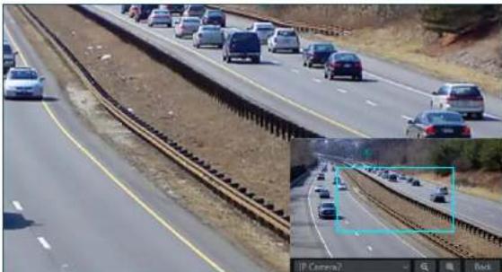
Refer to the picture as shown below. Drag the mouse from A to B to get a green rectangle and the rectangle area will be zoomed in.

natural_image
Highway scene with multiple vehicles and a covered bridge under clear sky (no visible text or symbols)
text_image
Camera Preset Cruise Preset Preset Name Call 1 preset1 2 preset2 Add Delete Save Position Zoom Focus Iris SpeedRefer to the picture as shown below. Drag the mouse from C to D to get a green rectangle and the rectangle area will be zoomed out.


Press and hold the le buon of the mouse on any area of the camera image to zoom in the image; press and hold the right buon to zoom out the Image.
Move the cursor of the mouse to the camera image and then slide the scroll wheel of the mouse forward to zoom in the image, slide the scroll wheel of the mouse backward to zoom out the image.
> OSD Seng
Go to PTZ protocol setng Interface and then set the protocol before you bring up the OSD. Click "OSD Menu" to go to camera OSD setng interface. Click To start OSD seng. The meanings of the buons are shown in the table below.
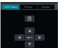
| Buon | Meaning |
| Click it to call main menu or enter the sub menu or conrm the sengs. | |
| Click it to call main menu or enter the sub menu or conrm the sengs. | |
| Click it to change the menu mode or decrease the menu value. | |
| Click it to change the menu mode or increase the menu value. | |
| Click it to go to the previous menu. | |
| Click it to go to the next menu. |
Preset Seng
You can also go to preset seng interface for preset seng, see 6.2 Preset Seng for details.
Cruise Seng
Click "Cruise" to go to cruise operaon tab and then click "Add" buon to pop up a window as shown below le. You can add 8 cruises for each dome at most.
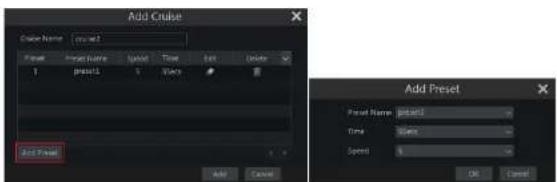
text_image
Add Cruise Name: new Time: 100% Impact: 1 Impact: 5 Trace: Add Preset Add Preset Preset Name: 0.0003 Time: 0.0002 Speed: 0 OK Cancel① Enter the cruise name in the "Add Cruise" window and then click "Add preset" to pop up the "Add Preset" window (Before adding preset to the cruise, please add preset of the dome rst).
② In the "Add Preset" window, select the preset name, preset me and preset speed and then click "OK" button.
In the "Add Cruise" window, you can click to reselect the preset, then change the preset me and speed. Click to delete the preset. Click "Add" buon to save the cruise.
Click ▶ to start the cruise and click □ to stop the cruise in the cruise list of the cruise operaon tab; click "Delete" buon to delete the selected cruise.
You can also go to cruise seng interface for cruise seng, see 6.3 Cruise Seng for details.
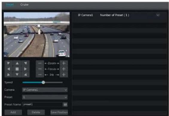
6.2 Preset Seng
Click Start→Sengs→Camera→PTZ→Preset to go to the Interface as shown below.
text_image
Insert Cruise IP Camera1 Number of Preset (1) Zoom Focus Ira Speed Camera IP Camera1 Preset: Preset Name preset1 Add Delete Save Position> Add preset
Select camera and then click "Add" buon to add preset; or click in the camera list on the right side of the interface to display the preset information of the dome and then click + to add preset. The operations of the "Add Preset" window are similar to that of the PTZ control interface; please see 6.1 PTZ Control Interface Introducon for details.
Edit preset
Select camera and preset. You can enter the new name of the preset and then click to save the new preset name. Adjust the rotang speed, posion, zoom, focus and iris of the preset and then click "Save Posion" to save the preset.
Delete Preset
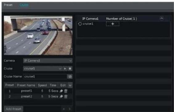
text_image
IP Camera1 Number of Cruise(1) cruise1 Camera IP Camera1 Cruise cruise1 Cruise Name: cruise1 Add Preset Preset Preset Name Speed Time Edit 1 preset1 5 5 Secs 2 preset2 5 5 Secs Add PresetAdd Cruise
Click In the camera list on the right side of the interface to display the cruise information of the dome and then click to add cruise. The operaons of the "Add Cruise" window is similar to that of the PTZ control interface; please see 6.1 PTZ Control Interface introducan for details.
Edit Cruise
Select the camera and cruise in the "Cruise" interface. Enter the new cruise name and then click to save the cruise name. Click "Add Preset" to add preset to the cruise. Click to edit the preset. Click to delete the preset from the cruise. Click one preset in the preset list and then click to move down the preset and click to move up the preset. Click to start the cruise and click to stop it.
Delete Cruise
7 Record& Disk Management
7.1 Record Conguraon
7.1.1 Mode Conguraon
Please format the HDDs before recording (refer to 7.5 Disk Management for details). Click Start→Sengs→Record→Mode Sengs to go to the mode sengs interface. You can set the record time under the "Manual Record Settings" and then click "Apply" to save the sengs. There are two record modes: auto mode and manual mode.
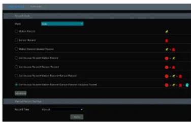
text_image
Material Selection Material: □ Material Resource □ Material Resource □ Material Resource Resource □ Limit volume: Material Resource □ Limit volume: Material Resource □ Limit volume: Material Resource Material: Material Resource Material: Material Resource Material: Material Resource Material: Material Resource Material: Material Resource Material: Material Resource Material: Material Resource Material: Material Resource Material: Material Resource Material: Material Resource Material: Material Resource Material: Material Resource Material: Material Resource Material: Material Resource Material: Material Resource Material: Material Resource Material: Material Resource Material: Material Resource Material: Material Resource Material: Material Resource Industrial Resource Industrial Resource Industrial Resource Industrial Resource Industrial Resource Industrial Resource Industrial Resource Industrial Resource Industrial ResourceAuto Mode
Moon Record: Moon alarm record will be enabled when moon alarm happens.
Sensor Record: Sensor alarm record will be enabled when sensor alarm happens.
Moon Record+Sensor Record: Moon/sensor alarm record will be enabled when moon/sensor alarm happens.
Connuous Record+Moon Record: Normal record is enabled all the me; moon alarm record will be started when moon alarm happens.
Connuous Record+Sensor Record: Normal record is enabled all the me; sensor alarm record will be started when sensor alarm happens.
Connuous Record+MoonRecord+Sensor Record: Normal record is enabled all the me; moon/sensor alarm record will be enabled when

text_image
Custom Record Mode Motion Record Sensor Record Continuous Record Analytics Record Add CancelSelect one auto mode to pop up the corresponding window. Set the encode, GOP, resoluon, FPS, bitrate type, quality, max bitrate and audio of each camera and then click "OK" to save the sengs. Please adjust the parameters according to the actual condition.
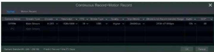
text_image
Continuous Record+Motion Record Name: Motion Record Camera Name: Stream Type: Cascade: Pre-Tender: FTS: Blade Type: Quality: Max Noise: Smooth Line Recommendation Design: Audio: GCP GPT500: Main Stream H: 205 150Hz 184Hz 38 VMI Higher 36490bps 2018-47180bps On: 88 IPC: Main Stream Raman Sandwidth: 24ft / 25ft Ms: Product Record Time: 75 Days OK CancelVideo Encode: the available opons will be H.265 and H.264 if the connected IP camera supports H.265, or the opon will be H.264 only.
GOP: group of pictures.
Resoluon: the higher the resoluon is, the clearer the image is.
FPS: the higher the frame rate is, the more uency the video is. However, more storage room will be taken up.
Bitrate Type: CBR and VBR are oponal. CBR means that no maer how much change is seen in the video scene, the compression bitrate will be
least constant 0/10 measures that the compressive blocks will be adjusted using excess voltages. For animals, forces that do not have a charge
Record & Disk Management
DVR User Manual

text_image
C:\Users\Newer\Proctics Current Data Current Data Current Data Current Data Current Data Current Data Current Data Current Data Current Data Current Data Current Data Current Data Current Data Current Data Current Data Current Data Current Data Current Data Current Data Current Data Current Data Current Data Current Data Current Data Current Data Current Data Current Data Current Data Current Data Current Data Current Data Current Data Current Data Current DataPre-alarm Record Time: set the me to record before the actual recording begins.
Post-alarm Record Time: set the me to record aer the actual recording is nished.
Expiraon Time: set the expiraon me for recorded video. If the set date is overdue, the recorded data will be deleted automatically.
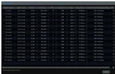
7.2 Encode Parameters Seng
Click Start→Settings→Record→Encode Parameters to go to the interface as shown below. Set the encode, resolution, FPS, GOP, bitrate type, quality, max bitrate and audio of main stream for each camera in "Event Recording Sengs" and "Schedule Recording Sengs" interfaces. Click "Apply" to save the sengs. You can set the record stream of each camera one by one or batch set them for all cameras.
| Company Name | Ticker Name | Symbol | Price | Country | Rating | Price Target | Country | Year End Price | % of Total Assets Invested in Fiscal Acq. (%) |
| Carmara | Mly Cnase | +2.25 | 104,800 | US | Buy | BUY | Agree | 300,000 | -39.64 |
| Carmara | Mly Cnase | +2.25 | 70,400 | US | Buy | BUY | Agree | 300,000 | -38.44 |
| Carmara | Mly Cnase | +2.25 | 50,400 | US | Buy | BUY | Agree | 300,000 | -38.44 |
| Carmara | Mly Cnase | +2.25 | 50,400 | US | Buy | BUY | Agree | 300,000 | -38.44 |
| Carmara | Mly Cnase | +2.25 | 504,800 | US | Buy | BUY | Agree | 300,000 | -38.44 |
| Carmara | Mly Cnase | +2.25 | 504,800 | US | Buy | BUY | Agree | 300,000 | -38.44 |
| Carmara | Mly Cnase | +2.25 | 504,600 | US | Buy | BUY | Agree | 300,000 | -38.44 |
Record & Disk Management
DVR User Manual
text_image
C:\Users\Outs C:\Users\Outs C:\Users\Outs C:\Users\Outs C:\Users\Outs C:\Users\Outs C:\Users\Outs C:\Users\Outs C:\Users\Outs C:\Users\Outs C:\Users\Outs C:\Users\Outs C:\Users\Outs C:\Users\Outs C:\Users\Outs C:100 C:100 C:100 C:100 C:100 C:100 C:100 C:100 C:100 C:100 C:100 C:100 C:100 C:100 C:100 C:100 C:100 C:250 C:250 C:250 C:250 C:250 C:250 C:250 C:250 C:250 C:250 C:250 C:250 C:250 C:250 C:250 C:250 C:250 C: C: C: C: C: C: C: C: C: C: C: C: C: C: C: C: C: C: C: C: C: C: C: C: C: C: C: C: C: C: C: C: C: C: C: C: C: C: C: C: C: C: C: C: C: C: C: C: C: C: C:7.3 Schedule Seng
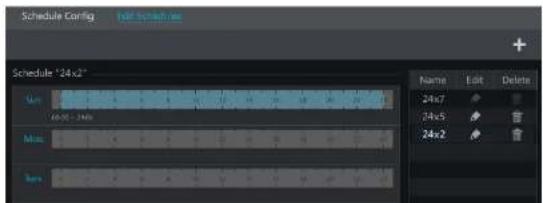
7.3.1 Add Schedule
Click Start→Sengs→Record→Record Schedule→Edit Schedules to go to the interface as shown below. "24×7", "24×5" and "24×2" are the default schedules; you cannot edit or delete "24×7" while "24×5" and "24×2" can be edited and deleted. Click the schedule name to display the detailed schedule information on the le side of the Interface. The seven rows stand for the seven days in a week and each row stands for 24 hours in a day. Blue stands for the selected me and gray stands for unselected me.
text_image
Schedule Config Schedule "24x2" Sum 60.0x - 24% Max 24x7 24x5 24x2 Name Edit Delete 24x7 24x5 24x2Record & Disk Management
DVR User Manual

text_image
Add Schedule Subscale Name: C:\Users\Subscale Name Add Add Add Add Add Add Add Add Add Add Add Add Add Add Add Add Add Add Add Add Add Add Add Add Add Add Add Add Add Add Add Add Add Add Add Add Add Add Add Add Add Add Add Add Add Add Add Add Add Add A## C##Set the schedule name and schedule me and then click "Add" to save the schedule. You can set day schedule or week schedule. Add buon; delete buon.
Set Day Schedule
Click and then drag the cursor on the me scale to set record me; click and then drag the cursor on the me scale to delete the selected area.
You can manually set the record start me and end me. Click 📄 and then click "Manual" on each day to pop up a window as shown below. Set the start and end me in the window and then click "OK" to save the sengs.

text_image
Added time manually Short Time 19.48 End Time 20.68Record & Disk Management
DVR User Manual
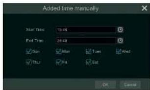
Set Week Schedule
Click 📄 or 📋 and then click "Manual" beside 📋 to set the week schedule. Refer to the picture below. Set the start and end me, check the days in the window and then click "OK" to save the sengs.
text_image
Added time manually Start Time 19:48 End Time 29:48 Run Man Times West Run Fat Set OK CancelClick "All" to set all week recording; click "Reverse" to swap the selected and unselected me in a week; click "Clear All" to clear all the selected area in a week.
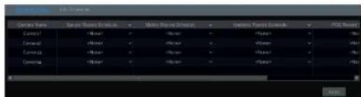
7.3.2 Record Schedule Conguraon
Click Start→Sengs→Record→Record Schedule→Schedule Conguraon to go to the interface as shown below. Set the schedule of sensor record, moon record, med record and intelligence record. Click "None" in the drop-down menu to clear the schedule. Click "Apply" to save the sengs.
text_image
Current Name Current Subtitle Current Subtitle Current Subtitle Current Subtitle Current Subtitle Current Subtitle Current Subtitle Current Subtitle Current Subtitle Current Subtitle Current Subtitle Current Subtitle Current Subtitle Current Subtitle Current Subtitle Current Subtitle Current Subtitle Current Subtitle Current Subtitle Current Subtitle Current Subtitle Current Subtitle Current Subtitle Current Subtitle Current Subtitle Current Sub标题 Current Subtitle Current Subtitle Current Subtitle Current Subtitle Current Subtitle Current Subtitle Current Subtitle Current Subtitle Current Subtitle Current Subtitle Current Subtitle Current Subtitle Current Subtitle Current Subtitle Current Subtitle Current Subtitle Current Subtitle Current Subtitle Current Subtitle Current Subtitle Current Subtitle Current Subtitle Current Subtitle Current Subtitle Current Sub titleSet the ming record schedule of each camera. See 7.3 Schedule Seng for details.
7.4.3 Moon Based Recording
Moon Based Recording: the system will start moon based recording when the moon object appears in the setup schedule. The setup steps are as follows:
① Set the moon based recording schedule of each camera. See 7.3 Schedule Setngfor details.
② Enable the moon and set the moon area of each camera. See 9.2.1 Moon Conguraon for details.
The camera will start moon based recording once you nish the above sengs.
7.4.4 Sensor Based Recording
① Set the sensor based recording schedule of each camera. See 7.3 Schedule Sengfor details.
② Set the NO/NC type of the sensor, enable the sensor alarm and then check and conjure the "Record". See 9.1 Sensor Alarm for details.
7.4.5 Analycs Recording
① Set the analytics recording schedule of each IP camera. See 7.3 Schedule Seng for details.
② Enable the intelligence alarm detecon (object detecon, excepon, tripwire or intrusion) and draw alert surface or warning area of each IP camera. See Event for details.
The camera will start analytics recording once you wish the above sengs. This funcon is only available for some IPCs.
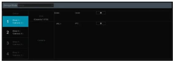
7.5 Disk
Click Start→Setngs→Disk→Disk Management to go to disk management interface. You can view the DVR's disk number and disk status and so on in the interface. Click "Formang" buon to format the HDD.
text_image
Storage Model Group 1 Image (1) Cancet (1) 2 Image (1) Cancet (1) 3 Image (1) Cancet (1) 4 Image (1) Cancet (1) DAR (DAR) (Capacity: 1.000) Camera Camera DAR DAR (DAR) (Capacity: 1.000) Camera DAR DAR (Capacity: 1.000) Camera DAR DAR (Capacity: 1.000)There are four disk groups. By using disk group, you can correspond the camera to disk (the record data of the camera in the group will be stored into the disks in the same group). The DVR with e-SATA interface supports e-SATA recording.
The added disks and cameras will be added into group one automatically. The disks and cameras in the groups can be deleted except group one (select a disk group and then click on the top right corner of the added disk or camera to delete it from the group). The deleted disks and cameras will be moved into group one automatically.
Each group can add the disks and cameras from other groups. Each disk and camera can only be added into one group. Select a disk group and then click + in the disk or camera row to pop up a window. Check the disks or cameras in the window and then click "Add".
7.5.3 View Disk and S.M.A.R.T. Informaon
Click Start→Settings→Disk→View Disk Informaon to view the HDD Informaon; click "S.M.A.R.T. Informaon" to view the working status of the HDD. Refer to the picture below.

text_image
File: Edit Edit Event No: WD/WD/QLP2-RX679L Edit Event #: WDG WD/HPURX-84385Y9 Temperature: 318 Playback& Backup
8.1 Instant Playback
Click ▶ on the tool bar at the boom of the preview camera window to play back the recorded video (click ▶ on the tool bar at the boom of the live view interface to set the default playback me). Refer to the picture below. Drag the playback progress bar to change the playback me. You can also click the right-click menu "Instant Playback" in the camera window and then set the Instant playback me to play back the record.

natural_image
Interior view of a modern building with large windows and a person standing near the entrance (no visible text or symbols)8.2 Playback Interface Introducon
Click 📄 on the tool bar at the boom of the live view interface or click Start→Playback to go to the playback interface as shown below (click on the tool bar at the boom of the live view interface to set the default playback me).

natural_image
Interior hallway with glass doors and wall-mounted screens (no visible text or symbols)the playback window to pop up the "Add Camera" window. Check the cameras in the window and then click "Add" to add playback camera. The system supports a maximum of 16 synchronous playback cameras.
The buons on the tool bar (area ①) at the boom of the playback interface are introduced in the table below.
| Buon | Meaning |
| Start buon. Click it to pop up area 2. | |
| Full screen buon. Click it to show full screen; click it again to exit the full screen. | |
| Screen mode buon. | |
| OSD ON buon. Click it to enable OSD; click it again to disable OSD. | |
| Stop buon. | |
| Rewind buon. Click it to play video backward. | |
| Play buon. Click it to play video forward. | |
| Pause buon. | |
| Deceleran buon. Click it to decrease the playing speed. | |
| Acceleran buon. Click it to increase the playing speed. | |
| Previous frame buon. It works only when the forward playing is paused in single screen mode. | |
| Next frame buon. It works only when the forward playing is paused in single screen mode. | |
| Click step backward 30s and click to forward 30s. | |
| Click it to show the water mark on the image; click inside the water mark. | |
| Event list/tag buon. Click it to view the event record of manual/schedule/sensor/moon and the tag informaon. | |
| Backup buon. Drag the mouse on the me scale to select the me periods and cameras, and then click the buon to back up the record. | |
| Backup status buon. Click it to view the backup status. | |
| Click it to Go to the live view interface; see Chapter 5 Live View Introduction for details. |
Click on the playback window to show the tool bar as shown in area ③; right click on the window to show the menu list. The tool bar and menu list are introduced in the table below.
| Buon | Menu List | Meaning |
| - | Move tool. Click it to move the tool bar anywhere. | |
| Enable Audio | Click it to enable audio. You can listen to the camera audio by enabling audio. | |
| Snapshot | Click it to snap. | |
| Zoom In | Click it to go to the zoom in interface. The zoom in interface is similar to that of the camera window in the live view interface.Click. Use the record playing: click to play the record. When the record is paused in forward playing mode, you can click to view the previous frame and click to view the next frame. | |
| Add Tag | Click it to add tag. You can play back the record by searching the added tag. Click it and then enter the tag name in the popup window. Click "Add" to add tag. | |
| Switch Camera | Click it to switch the playback camera. Click it and then check the camera in the popup window. Click "OK" to change the camera. | |
| Close Camera | Click it to close the playback camera. |
Introducon of area ④:
You can check the record type as required for record playback; rst you should click on the tool bar at the boom of the interface to clear all the playback camera, then check the record type ( manual record; sensor based record; moon based record; schedule record; analytics record; and nally click the playback window to add camera for playback (the record me scale will show the record data of
Alarm Management
DVR User Manual
8.3 Smart Playback
● Smart Playback Sengs
Click 📄 to go to the following interface. Set the value of "Speed of non-interest video" (Please skip this one if you click "Skip non-interest video"), "Speed of interest video" and "Intrusion percentage".
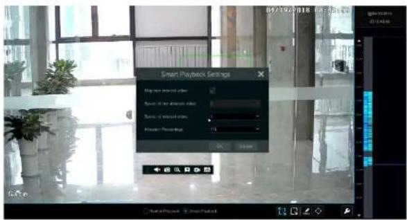
text_image
Smart Playback Settings Play new installed video Apply all new installed video Scene of installed video Inspector: Previewer OK Cancel● Smart Playback by Drawing Rectangle

natural_image
Interior view of a modern office or library with large windows and a person in pink attire standing near the window (no visible text or symbols)Alarm Management
DVR User Manual

text_image
Street photo with visible store signboards and a person walking in a modern indoor space● Smart Playback by Drawing Quadrilateral
Click and draw a quadrangle in the desired area. Then the system will automatically search the record les of this area. The cyan blocks indicate that there are intelligent recording les. Move the cursor to such block and click to play the record.

text_image
Street photo with visible store signboards and a green bounding box overlay on a building interiorAlarm Management
DVR User Manual
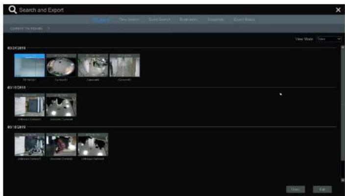
text_image
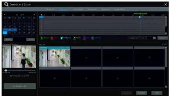
Search and Export Current Search View Book Time Search Smart Search Subspecies Kingshik Exact Status 03/24/2019 The Search Carboard Carboard Carboard 03/18/2019 [ ] [ ] [ ] [ ] [ ] 03/18/2019 [ ] [ ] [ ] [ ] [ ]② Select one camera in the interface and then click "Open" button.
⑧ Click the image box to play the record in the small playback box on the le side of the interface (the box which has image inside indicates that the record data exist).
① Refer to the picture below. Drag the color blocks on the me scale to select the record data and then click "Export" buon to pop up the "Record Backup" window as shown below. Select the device name, backup format and path and then click "Export" buon to start the backup.
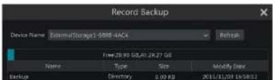
text_image
Record Backup Device Name: ExmmatStorage1-5880-4ACs Name: 28.96 GB, A1.29.27 GB Type: Size: Modify Date: backup: Directory: 0.00 kg 2011/10/01 (access)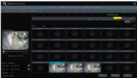
text_image
Search and Export Volume: 100% Volume: 100% Volume: 100% Volume: 100% Volume: 100% Volume: 100% Volume: 100% Volume: 100% Volume: 100% Volume: 100% Volume: 100% Volume: 100% Volume: 100% Volume: 100% Volume: 100% Volume: Volume: Volume: Volume: Volume: Volume: Volume: Volume: Volume: Volume: Volume: Volume: Volume: Volume: Volume: Volume: Volume: Volume: Volume: Volume: Volume: Volume: Volume: Volume: Volume: Volume: Volume: Volume: Volume: Volume: Volume: Volume: Volume: Volume: Volume: Volume: Volume: Volume: Volume: Volume: Volume: Volume: Volume: Volume: Volume: Volume: Volume: Volume: Volume: Volume: Volume:Time Slice Search:
Method One: Click "Year", "Month" or "Day" buon under the record me scale to select the me slice mode. In "Day" mode, click on the le/right side of the me scale to view the record of the last/next day; click "Minute" in the "Picture" open under the me scale to select "Minute" mode (In "Minute" mode, click the me scale to change the me of the 60 display windows) and click "Hour" to select "Hour" mode.
Method Two: Click > beside "Camera Thumbnail" on the le top corner of the interface to select the me slice mode.
Method Three: Right-click the mouse on any area of the me-sliced interface to go back to the upper interface.
8.4.2 Time Search
① Click Start→Search and Export→Time Search to go to the "Time Search" tab as shown below.
② Click + on the boom of the interface to add playback camera. A maximum of 16 cameras can be added for playback. Click "Modify" on the top right corner of the camera window to change the camera and click "Clear" to remove the camera.
⑧ Click the camera window to play the record in the small playback box on the le side of the Interface. You can set the date on the top le of the interface, check the event type as required and click the me scale or click under the me scale to set the me. The camera window will
① Click Start→Search and Export→Event Search to go to "Event Search" tab as shown below.

text_image
Search and Export File Edit View Insert Tools Help Tools Help Tools Help Tools Help Tools Help Tools Help Tools Help Tools Help Tools Help Tools Help Tools Help Tools Help Tools Help Tools Help Tools Help Tools Help Tools Help Tools Help Tools Help Tools Help Tools Help Tools Help Tools Help Tools Help Tools Help Tools Help Tools Help Tools Help Tools Help Tools Help Tools Help Tools Help Tools Help Tools Help Tools Help Tools Help Tools Help Tools Help Tools Help Tools Help Tools Help Tools Help Tools Help Tools Help Tools Help Tools Help Tools Help Tools Help Tools Help Tools Help Tools help tools help tools help tools help tools help tools help tools help tools help tools help tools help tools help tools help tools help tools help tools help tools help tools help tools help tools help tools help tools help tools help tools help tools help tools help tools help tools help tools help tools help tools help tools help tools help tools help tools help tools help tools help tools help tools help tools help tools help tools help tools help tools help tools help tools help tools help tools help tools help tools help tools help tools help teams help teams help teams help teams help teams help teams help teams help teams help teams help teams help teams help teams help teams help teams help teams help teams help teams help teams help teams help teams help teams help teams help teams help teams help teams help teams help teams help teams help teams help teams help teams help teams help teams help teams help teams help teams help teams help teams help teams help teams help teams help teams help teams help teams help teams help teams help teams help teams help teams help teams help groups help groups help groups help groups help groups help groups help groups help groups help groups help groups help groups help groups help groups help groups help groups help groups help groups help groups help groups help groups help groups help groups help groups help groups help groups help groups help groups help groups help groups help groups help groups help groups help groups help groups help groups help groups help groups help groups help groups help groups help groups help groups help groups help groups help groups help groups help groups help groups help groups help groups help teams help teams help teams help teams help teams help teams help teams help teams help teams help teams help teams help teams help teams help teams help teams help teams help teams helps to switch or switch to switch to switch to switch to switch to switch to switch to switch to switch to switch to switch to switch to switch to switch to switch to switch to switch to switch to switch to switch to switch to switch to switch to switch to switch to switch to switch to switch to switch to switch to switch to switch to switch to switch to switch to switch to switch to switch to switch to switch to switch to switch to switch to switch to switch to switch to switch to switch to switch to switch to switch for all users. For all users, the number of users is calculated by using the sum of the number of users for each user. The total number of users is calculated by using the sum of the number of users for each user. The total number of users is calculated by using the sum of the number of users for each user. The total number of users is calculated by using the sum of the number of users for each user. The total number of users is calculated by using the sum of the number of users for each user. The total number of users is calculated by using the sum of the number of users for each user. The maximum value is 10000000000000000000000000000000000000000000000000000000000000000000000000000000000000000000000000000Alarm Management
DVR User Manual
8.4.4 Bookmark Search
Only if you add the tags can you play the record by tag search. Click Start→Playback to go to the playback interface and then click 📄 on the boom of the camera window to add bookmarks when you want to mark the playback me point of the selected camera.
Click Start→Search and Export→Bookmarks to go to "Bookmarks" tab.
text_image
Search and Export File Edit View Insert Search Window Help Help Help Help Help Help Help Help Help Help Help Help Help Help Help Help Help Help Help Help Help Help Help Help Help Help Help Help Help Help Help Help Help Help Help Help Help Help Help Help Help Help Help Help Help Help Help Help Help Help Help Help Help Help Help Help Help Help Help Help Help Help Help Help Help Help Help Help Help Help Help Help Help Help Help Help Help Help Help Help Help Help Help Help Help Help Help Help Help Help Help Help Help Help Help Help Help Help Help Help help help help help help help help help help help help help help help help help help help help help help help help help help help help help help help help help help help help help help help help help help help help help help help help help help help help help help help help help help help help help help help help help help help help help help help help help help help help help help help help help help help help help help help help help help help help help help help help help help help help help helps Name: C#e##, C#e##, C#e##, C#e##, C#e##, C#e##, C#e##, C#e##, C#e##, C#e##, C#e##, C#e##, C#e##, C#e##, C#e##, C#e##, C#e##, C#e##, C#e##, C#e##, C#e##Click the interface to play the record. Click to else the tag name. Click to delete the tag.
8.4.5 Snapshots
Click Start→Search and Export→Snapshots to go to "Snapshots" tab. The system will display all the captured images automatically in the list.

text_image
Search and Export File Edit View Insert Search Tools Remove Search Name Document Name Document Name Document Name Document Name Document Name Document Name Document Name Document Name Document Name Document Name Document Name Document Name Document Name Document Name Document Name Document Name Document Name Document Name Document Name Document Name Document Name Document Name Document Name Document Name Document Name Document Name Document Name Document Name Document Name Document Name Document Name Document Name Document Name Document Name Document Name Document Name Document Name Document Name Document Name Document Name Document Name Document Name Document Name Document Name Document Name Document Name Document Name Document Name Document Name Document Name Document Names Document Names Document Names Document Names Document Names Document Names Document Names Document Names Document Names Document Names Document Names Document Names Document Names Document Names Document Names Document Names Document Names Document Names Document Names Document Names Document Names Document Names Document Names Document Names Document Names Document Names Document Names Document Names Document Names Document Names Document Names Document Names Document Names Document Names Document Names Document Names Document Names Document Names Document Names Document Names Document Names Document Names Document Names Document Names Document Names Document Names Document Names Document Names Document Names Document Names DocumentNames Document Names Document Names Document Names Document Names Document Names Document Names Document Names Document Names Document Names Document Names Document Names Document Names Document Names Document Names Document Names Document Names Document Names Document Names Document Names Document Names Document Names Document Names Document Names Document Names Document Names Document Names Document Names Document Names Document Names Document Names Document Names Document Names Document Names Document Names Document Names Document Names Document Names Document Names Document Names Document Names Document Names Document Names Document Names Document Names Document Names Document Names Document Names Document Names Document Names Document NAMES Document Names Document Names Document Names Document Names Document Names Document Names Document Names Document Names Document Names Document Names Document Names Document Names Document Names Document Names Document Names Document Names Document Names Document Names Document Names Document Names Document Names Document Names Document Names Document Names DocumentNames DocumentNames DocumentNames DocumentNames DocumentNames DocumentNames DocumentNames DocumentNames DocumentNames DocumentNames DocumentNames DocumentNames DocumentNames DocumentNames DocumentNames DocumentNames DocumentNames DocumentNames DocumentNames DocumentNames DocumentNames DocumentNames DocumentNames DocumentNames DocumentNames DocumentNames DocumentNames DocumentNames DocumentNames DocumentNames DocumentNames DocumentNames DocumentNames DocumentNames DocumentNames DocumentNames DocumentNames DocumentNames DocumentNames DocumentNames DocumentNames DocumentNames DocumentNames DocumentNamesDocumentNo. 1. 2. 3. 4. 5. 6. 7. 8. 9. 10. 11. 12. 13. 14. 15. 16. 17. 18. 19. 20. 21. 22. 23. 24. 25. 26. 27. 28. 29. 30. 31. 32. 33. 34. 35. 36. 37. 38. 39. 40. 41. 42. 43. 44. 45. 46. 47. 48. 49. 50. 51. 52. 53. 54. 55. 56. 57. 58. 59. 60. 61. 62. 63. 64. 65. 66. 67. 68. 69. 70. 71. 72. 73. 74. 75. 76. 77. 78. 79. 80. 81. 82. 83. 84. 85. 86. 87. 88. 89. 90. 91. 92. 93. 94. 95. 96. 97. 98. 99. 100.Click 📄 to delete the image. Click 📄 to pop up the "Export" window. Select the device name and save path in the window and then click "Save" buon.
Click to pop up the "View Image" window. Click to export the Image. Click to view the previous Image; click to view the next image; click delete the image; click to play all the images.
Alarm Management
DVR User Manual
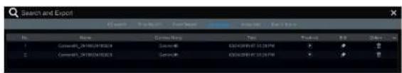
8.4.6 View Export Status
Click Start→Search and Export→Export Status or click 📄 on the tool bar at the boom of the playback interface to view the export status.
9 Alarm Management
9.1 Sensor Alarm
To complete the entire sensor alarm settings, you should enable the sensor alarm of each camera and then set up the alarm handling of each camera.
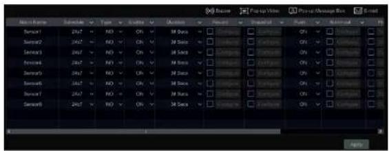
① Click Start→Sengs→Alarm→Sensor Alarm to go to the following interface.
text_image
Scene Scene1 Scene2 Scene3 Scene4 Scene5 Scene6 Scene7 Scene8 Scene9 Scene10② Select schedule and the alarm type (NO or NC) according to trigger type of the sensor.
③ Enable the sensor alarm of each camera.
① Check the "Duraon", "Record", "Snapshot", "Push", "Alarm-out" and "Preset" and enable or disable the "Buzzer", "Pop-up Video", "Pop-up Message Box" and "E-mail" as required.
⑤ Click "Apply" to save the sengs.
The conguraon steps of the above menoned alarm linkages are as follows.
Duraon: it refers to the interval me between the adjacent moon detecons. For instance, if the duraon me is set to 10 seconds, once the system detects a moon, it will go to alarm and would not detect any other moon (specic to camera) in 10 seconds. If there is another moon detected during this period, it will be considered as connuous movement: otherwise it will be considered as a single moon.
Alarm Management
DVR User Manual
Pop-up Video: Aer camera seng, the system will pop up the corresponding video automatically when the sensor alarm is triggered. To set the duraon me of the video, please see 9.5.3 Display for details.
Pop-up Message Box: if enabled, the system will pop up the corresponding alarm message box automatically when the sensor alarm is triggered. To set the duration of the message box, please see 9.5.3 Display for details.
E-mail: if enabled, the system will send an e-mail when the sensor alarm is triggered. Before you enable the email, please conjure the recipient's e-mail address rst (see 11.1.5 E-mail Conguraon for details).
9.2 Moon Alarm
Moon Alarm: when the moon object appears in the specied area, it will trigger the alarm. You should enable the moon of each camera rst and then set the alarm handling of the camera to complete the whole conguraon of the moon alarm.
9.2.1 Moon Conguraon
① Click Start→Sengs→Camera→Moon to go to the following Interface.

text_image
Camera Name M10 Sensitivity Duration IP Camera1 ON 0 20 Step IP Camera2 ON 0 20 Steps IP Camera3 ON 0 20 Steps IP Camera4 ON 0 20 Steps ... Control Current Speed Control IP Camera5 - - - - - - - - - - - - - - - - - - - - - - - - - - - - - - - - - - - - - - - - - - - - - - - - - - - - - - - - - - - - - - - - - - - - - - - - - - - - - - - - - - - - - - - - + - + + + + + + + + + + + + + + + + + + + + + + + + + + + + + + + + + + + + + + + + + + + + + + + + + + + + + + + + + + + + + + + + + + + + + + + + + + + + + + + + + + + + + + + + + + + + + + + + + + + + + - + - + - + - + - + - + - + - + - + - + - + - + - + - + - + - + - + - + - + - + - + - + - + - + - + - + - + - + - + - + - + - + - + - + - + - + - + - + - + - + - + - + - + - + - + - + - + - + - + - + -② Select the camera, enable the moon and set the sensitivity and duration of the camera.
text_image
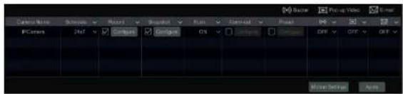
Cable Name Scales Position Spread Run Control Play Photo Video Photo PCovers Ref Gambus Gigiligo On Off Off Off Media Settings Audio② Enable or disable "Record", "Snapshot", "Push", "Alarm-out", "Preset", "Buzzer", "Pop-up Video" and "E-mail". The alarm handling sengs of moon alarm the same as the sensor alarm (see 9.1 Sensor Alarm for details).
③ Click "Apply" to save the settings. You can click "Moon Sengs" to go to the moon conguraon interface.
9.3 Smart Event
9.3.1 Object Detecon
Object Detecon Conguraon:
① Click Start→Sengs→Camera→Intelligent Analys→Object Detecon to go to the following interface.
② Select the camera, enable the object detector and set the detect type. There are two detect types: Abandoned object and missing object.
Abandoned object: Alarms will be triggered if there are arcs le in the pre-dened detecon area.
Missing object: Alarms will be triggered if there are arcs missing in the detector area drawn by the users.
⑧ Select the alarm area. A maximum of 4 alarm areas can be set.
④ Draw the alarm area of the object detector. Refer to the interface as shown above. Check "Draw Area" and then click around the area where you want to set as the alarm area in the image (the alarm area should be a closed area). Uncheck the "Draw Area" if you nish the drawing. Click the "Clear" to delete the alarm area.
⑤ Click "Apply" to save the sengs.
© Click "Processing Mode" to go to the alarm handling conguraon Interface of object detecon.
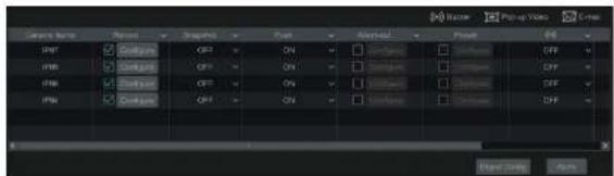
text_image
Image export Source: JPEG Output: JPEG Input: JPEG Output: JPEG Output: JPEG Output: JPEG Output: JPEG Output: JPEG Output: JPEG Output: JPEG Output: JPEG Output: JPEG Output: JPEG Output: JPEG Output: JPEG Output: JPEG Output: JPEG Output: JPEG Output: JPEG Output: JPEG Output: JPEG Output: JPEG Output: JPEG Output: JPEG Output: JPEG Output: JPEG Output: JPEG Output: JPEG 输出类型: Ctrl+1 Ctrl+2 Ctrl+3 Ctrl+4 Ctrl+5 Ctrl+6 Ctrl+7 Ctrl+8 Ctrl+9 Ctrl+10 Ctrl+11 Ctrl+12 Ctrl+13 Ctrl+14 Ctrl+15 Ctrl+16 Ctrl+17 Ctrl+18 Ctrl+19 Ctrl+20 Ctrl+21 Ctrl+22 Ctrl+23 Ctrl+24 Ctrl+25 Ctrl+26 Ctrl+27 Ctrl+28 Ctrl+29 Ctrl+30 Ctrl+31 Ctrl+32 Ctrl+33 Ctrl+34 Ctrl+35 Ctrl+36 Ctrl+37 Ctrl+38 Ctrl+39 Ctrl+40 Ctrl+41 Ctrl+42 Ctrl+43 Ctrl+44 Ctrl+45 Ctrl+46 Ctrl+47 Ctrl+48 Ctrl+49 Ctrl+50 Ctrl+51 Ctrl+52 Ctrl+53 Ctrl+54 Ctrl+55 Ctrl+56 Ctrl+57 Ctrl+58 Ctrl+59 Ctrl+60 Ctrl+61 Ctrl+62 Ctrl+63 Ctrl+64 Ctrl+65 Ctrl+66 Ctrl+67 Ctrl+68 Ctrl+69 Ctrl+70 Ctrl+71 Ctrl+72 Ctrl+73 Ctrl+74 Ctrl+75 Ctrl+76 Ctrl+77 Ctrl+78 Ctrl+79 Ctrl+80 Ctrl+81 Ctrl+82 Ctrl+83 Ctrl+84 Ctrl+85 Ctrl+86 Ctrl+87 Ctrl+88 Ctrl+89 Ctrl+90 Ctrl+91 Ctrl+92 Ctrl+93 Ctrl+94 Ctrl+95 Ctrl+96 Ctrl+97 Ctrl+98 Ctrl+99 Ctrl+100② Enable or disable "Snapshot", "Push", "Alarm-out", "Preset", "Buzzer", "Pop-up Video" and "E-mail". The alarm handling seng of object detecon alarm is similar to that of the sensor alarm (see 9.1 Sensor Alarm for details).
⑧ Click "Apply" to save the sengs. You can click "Object Cong" to go to the object detecon conguraon Interface.
9.3.2 Tampering
Tampering Conguraon:
① Click Start→Sengs→Camera→Intelligent Analys→Tampering to go to the following interface.

text_image
Stream Change Video Blurer Audio Color Dot Severable Channel Name Channel01 ChannelA ChannelB OFF OFF OFF OFF OFF OFF 1 1 1 1 1 1 1 1 1 1 1 1 1 1 1 1 1 1 1 1 1 1 1 1 1 1 1 1 1 1 1 1 1 1 1 1 1 1 1 1 1 1 1 1 1 1 1 1 1 1 2 2 2 2 2 2 2 2 2 2 2 2 2 2 2 2 2 2 2 2 2 2 2 2 2 2 2 2 2 2 2 2 2 2 2 2 2 2 2 2 2 2 2 2 2 2 2 2 2 2 3② Select the camera and enable the relevant detector as needed.
Scene Change: Alarms will be triggered if the scene of the monitor video has changed.

text_image
Camera lens Camera(0) Camera(1) Camera(2) Camera(3) Camera(4) Camera(5) Output Output Output Output Output Output Output Output Output Output Output Output Output Output Output Output Output Output Output Output Output Output Output Output Output Output Output Output Output Output Output Output Output Output Output Output Output Output Output Output Output Output Output Output Output Output Output Output Output Output Output② Enable or disable "Snapshot", "Push", "Alarm-out", "Preset", "Buzzer", "Pop-up Video" and "E-mail". The alarm handling seng of excepon detecon alarm is similar to that of the sensor alarm (see 9.1 Sensor Alarm for details).
(3) Click "Apply" to save the sengs. You can click "Excepon Cong" to go to the excepon detecon conguraon interface.
9.3.3 Tripwire
Line Crossing Conguraon:
Alarms will be triggered if someone or something crosses the pre-dened alarm line.
① Click Start→Sengs→Camera→Intelligent Analycs→Tripwire to go to the following interface.

text_image
Timeline Duration Line Duration Control Time IPMA CHF 20 Bits AV-03 IPWL CHF 5 Bits 1 APWT CHF 20 Bits IPMS CHF 20 Bits Dose Map Filter Processing Mode Apply② 1.1.1

text_image
Camera Camera1 Camera2 Camera3 Camera4 Camera5 Camera6 Camera7 Camera8 Camera9 Camera10 Camera11 Camera12 Camera13 Camera14 Camera15 Camera16 PC CAMERA Recognition □ Camera 1 □ Camera 2 □ Camera 3 □ Camera 4 □ Camera 5 □ Camera 6 □ Camera 7 □ Camera 8 □ Camera 9 □ Camera 10 □ Camera 11 □ Camera 12 □ Camera 13 □ Camera 14 □ Camera 15 □ Camera 16 □ Camera 17 □ Camera 18 □ Camera 19 □ Camera 20 □ Camera 21 □ Camera 22 □ Camera 23 □ Camera 24 □ Camera 25 □ Camera 26 □ Camera 27 □ Camera 28 □ Camera 29 □ Camera 30 □ Camera 31 □ Camera 32 □ Camera 33 □ Camera 34 □ Camera 35 □ Camera 36 □ Camera 37 □ Camera 38 □ Camera 39 □ Camera 40 □ Camera 41 □ Camera 42 □ Camera 43 □ Camera 44 □ Camera 45 □ Camera 46 □ Camera 47 □ Camera 48 □ Camera 49 □ Camera 50 □ Camera 51 □ Camera 52 □ Camera 53 □ Camera 54 □ Camera 55 □ Camera 56 □ Camera 57 □ Camera 58 □ Camera 59 □ Camera 60 □ Camera 61 □ Camera 62 □ Camera 63 □ Camera 64 □ Camera 65 □ Camera 66 □ Camera 67 □ Camera 68 □ Camera 69 □ Camera 70 □ Camera 71 □ Camera 72 □ Camera 73 □ Camera 74 □ Camera 75 □ Camera 76 □ Camera 77 □ Camera 78 □ Camera 79 □ Camera 80 □ Camera 81 □ Camera 82 □ Camera 83 □ Camera 84 □ Camera 85 □ Camera 86 □ Camera 87 □ Camera 88 □ Camera 89 □ Camera 90 □ Camera 91 □ Camera 92 □ Camera 93 □ Camera 94 □ Camera 95 □ Camera 96 □ Camera 97 □ Camera 98 □ Camera 99 □ Camera Drawing Ctrl+N Apply② Enable or disable "Snapshot", "Push", "Alarm-out", "Preset", "Buzzer", "Pop-up Video" and "E-mail". The alarm handling seng of line crossing alarm is similar to that of the sensor alarm (see 9.1 Sensor Alarm for details).
③ Click "Apply" to save the sengs. You can click "Crossing Cong" to go to the line crossing conguraon interface.
9.3.4 Intrusion Detecon
Intrusion Conguraon:
Alarms will be triggered if someone or something intrudes into the pre-dened area.
① Click Start→Sengs→Camera→Intelligent Analys→Intrusion Detecon to go to the following interface.

Alarm Management
DVR User Manual
⑥ Click "Processing Mode" to go to the alarm handling conguraon Interface of intrusion detecon.
Intrusion Detecon Alarm Handling Conguraon:
① Click Start→Sengs→Alarm→Intelligence Alarm→Intrusion to go to the following interface.

text_image
Camera Camers1 Camers2 Camers3 Camers4 Camers5 Camers6 Camers7 Camers8 Camers9 Camers10 Camers11 Camers12 Camers13 Camers14 Camers15 Camers16 Camers17 Camers18 IP CAMERA Output Output Mode Control Control Control Control Control Control Control Control Control Control Control Control Control Control Control Control Control Control Control Control Control Control Control Control Control Control Control Control Control Control Control Control Control Control Control Control Control Control Control Control Control Control Control Control Control Control Control Control Control Control System1② Enable or disable "Snapshot", "Push", "Alarm-out", "Preset", "Buzzer", "Pop-up Video" and "E-mail". The alarm handling setng of intrusion detecon alarm is similar to that of the sensor alarm (see 9.1 Sensor Alarm for details).
⑧ Click "Apply" to save the settings. You can click "Intrusion Cong" to go to the Intrusion detecon conguraon Interface.
9.4 Excepon Alarm
9.4.1 IPC Oine Sengs
©
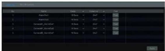
text_image
File Name Cancel Sequence Type 1 OpenOut 0 Series 24x7 Total 2 OpenShift 0 Series 34x7 Total 3 S generalOut 0 Series 24x7 Total 4 S generalOut 0 Series 24x7 Total 5 S generalOut 0 Series 34x7 Total Apply② Set the delay me and the schedule of each alarm-out. You can click "Edit Schedules" to edit the schedules (see 7.3.1 Add Schedule for details).
③ Click "Apply" to save the settings. You can click "Test" to test the alarm output.
9.5.2 E-mail
Click Start→Sengs→Alarm→Event Nocaon→E-mail to go to the e-mail conguraon Interface. Set the e-mail address of the recipients. See 11.1.5 E-mail Conguraon for details.
9.5.3 Display
Click Start→Sengs→Alarm→Event Nocao→Display to go to the display conguraon interface. Set the duraon me of the pop-up video and the pop-up message box. Click "Apply" to save the sengs.

text_image
Pre-up Video Duration 1# Socs Output Main Output Pre-up Message Box ✓ Next step levelAlarm Management
DVR User Manual
9.5.5 Push Message
Click Start→Setngs→Alarm→Event Nocaoon→Push Message to go to the Interface as shown below. Check "Enable" and then click "Apply" buon to save the sengs. If Push Server is online, it will push messages to the mobile clients.
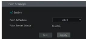
9.5.6 Alarm Server
Go to Alarm→Alarm Server interface as shown below.
Enable the alarm server and enter server address and port of the alarm server. Then select protocol. If "Send Heartbeat" is enabled, set the interval mes. Aer that, test the effectiveness of the alarm server. Having tested successfully, please click "Apply". When an alarm occurs, the device will transfer the alarm event to the alarm server. If an alarm server is not needed, there is no need to congregate this secon.
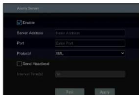
text_image
Aeros Server Enable Server Address: East Address Port: East Port Protocol: XML Send /Forward Internal Time(s): 10 Test Apply9.6 Manual Alarm
Alarm Management
DVR User Manual
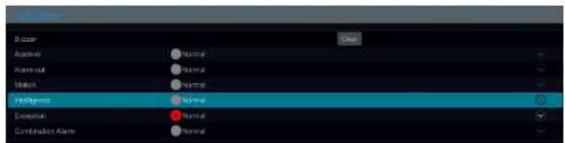
text_image
Alarm Alarm-out Main Failure Exceptional Combined Alert NoneClick "Clear" buon to stop the buzzer when the buzzer alarm happens. Click 📋 to view the detail informaon as shown below.

text_image
Action Action Application Main Main group Computer Device Name Name Time Date: 19:36.2014 (19:15) Date: No. 2018 Trigger Active Trigger Cluster: ONIf the excepon informaon is more than one page, you can enter the number in the box and then click jump to the specied page. Click
< / > to view the excepon alarm informaon in the previous/next page. Click
play the alarm record.
10 Account & Permission Management
10.1 Account Management
Click Start→Sengs→Account and Authority→Account→Edit User to go to the Interface as shown below.

text_image
Local Camera Management Local Camera Management Local System Settings Local System Settings Local System Settings Local System Settings Local System Settings Local System Settings Local System Settings Local System Settings Local System Settings Local System Settings Local System Settings Local System Settings Local System Settings Local System Settings Local System Settings Local System Settings Local System Settings Local System Settings Local System Settings Local System Settings Local System Settings Local System Settings Local System Settings Local System Settings Local System Settings Local System Guidelines Local System Guidelines Local System Guidelines Local System Guidelines Local System Guidelines Local System Guidelines Local System Guidelines Local System Guidelines Local System Guidelines Local System Guidelines Local System Guidelines Local System Guidelines Local System Guidelines Local System Guidelines Local System Guidelines Local System Guidelines Local System Guidelines Local System Guidelines Local System Guidelines Local System Guidelines Local System Guidelines Local System Guidelines Local System Guidelines Local System Guidelines Local System Guidelines Local System实施细则 Local System Guidelines Local System Guidelines Local System Guidelines Local System Guidelines Local System Guidelines Local System Guidelines Local System Guidelines Local System Guidelines Local System Guidelines Local System Guidelines Local System Guidelines Local System Guidelines Local System Guidelines Local System Guidelines Local System Guidelines Local System Guidelines Local System Guidelines Local System Guidelines Local System Guidelines Local System Guidelines Local System Guidelines Local System Guidelines Local System Guidelines Local System Guidelines Local System guidelinesArea ① displays the user permissions. Area ② displays the user list. Click the user in the list to display its user permissions in area ①.
There are three default permission groups ("Administrator", "Advanced" and "Common") available when adding accounts. You can manually add new permission group (see 10.3.1 Add Permission Group for details).
Only admin and the users that have the "Account and Authority" permission can manage the system's accounts. Group "Administrator" owns all the permissions displayed in area ① except "Account and Authority" and its permissions cannot be changed while the permissions of "Advanced" and "Common" can be changed.
Account & Permission Management
DVR User Manual
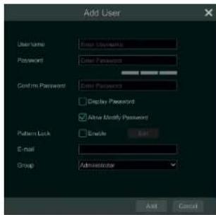
text_image
Add User User Name: Enter Passwords Password: Enter Password Confirm Password: Enter Password Display Password: Allow Modify Password! Pattern Lock: Enable E-mail: Group: Administrator Add Cancel② Set the username, password and group. User can also set the paern lock here. The e-mail address is oponal. Click "Add" to add the user.
10.1.2 Edit User
Click Start→Settings→Account and Authority→Account→Edit User and then click in the user list or double click the user to edit the user informaon. Click to select the user {the user admin cannot be deleted}.

text_image
Username admin Group Administrator Modify Password Modify Pattern Lock Edit User Edit Security Question 1 Administrator Edit User Recovery PasswordEdit Security Queson
Account & Permission Management
DVR User Manual

text_image
Modify Pattern Lock Current Password Pattern Lock Enable OK CancelEnter current password and then check "Enable" to input paem lock.
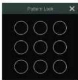
Recover Password
Click "Recover Password" to reset the password.
Edit User
Click "Edit User" to pop up the window as shown below. The admin is enabled, its permission control is closed and permission group cannot be changed by default. You can enable or disable other users (if disabled, the user will be invalid), open or close their permission control (if closed, the user will get all the permissions which admin has) and set their permission groups. Click "OK" to save the settings.

Account & Permission Management
DVR User Manual
10.3 Permission Management
10.3.1 Add Permission Group
Click Start→Sengs→Account and Authority→Account→Edit Permission Group to go to the interface as shown below.

text_image
Group Active/Active Parameters ✓ Local Command Management ✓ Remote Current Management ✓ Remote Login ✓ Risk Management ✓ Audio Tools ✓ Home Management ✓ Network Management ✓ Schedule Management ✓ Front Select Generator Management ✓ Local System Settings ✓ Remote System Settings Local Remote Groups Position Language Output Fit Type Administrative Advanced Current Current1 Current2 Current3 Current4 Current5 Current6 Current7 Current8 Current9 Current10 Current11 Current12 Current13 Current14 Current15 Current16 Current17 Current18 Current19 Current20 Current21 Current22 Current23 Current24 Current25 Current26 Current27 Current28 Current29 Current30 Current31 Current32 Current33 Current34 Current35 Current36 Current37 Current38 Current39 Current40 Current41 Current42 Current43 Current44 Current45 Current46 Current47 Current48 Current49 Current50 Current51 Current52 Current53 Current54 Current55 Current56 Current57 Current58 Current59 Current60 Current61 Current62 Current63 Current64 Current65 Current66 Current67 Current68 Current69 Current70 Current71 Current72 Current73 Current74 Current75 Current76 Current77 Current78 Current79 Current80Click + to add permission group. Set the group name, check the permissions as needed and then set the "Local" and "Remote" permissions. Click "Add" to save the sengs.
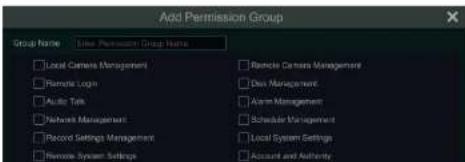
text_image
Add Permission Group Group Name: Use Permission Group Name Local Camera Management Remote Logs Audio Talk Network Management Record Settings Management Remote System Settings Remote Camera Management Data Management Alarm Management Scheduler Management Local System Settings Account and AuthorityAccount & Permission Management
DVR User Manual
10.4 Block and Allow List
① Click Start→Sengs→Account and Authority→Security to go to the following interface.
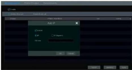
text_image
Add SP System IF If Degree Add None OK Cancel② Check "Enable" and then choose "Enable Allow List" or "Enable Block List" (the PC client of which the IP address is in the allow list can access DVR remotely while the PC client in the block list cannot).
③ Add IP/IP segment/MAC. Click "Add IP" or "Add MAC" buon and then check "Enable" in the popup window (only if you check it can the IP/IP segment/MAC you add be eeve). Enter the IP/IP segment/MAC and then click "OK" buon. In the above interface, click edit IP/IP segment/MAC, click to delete it. Click "Apply" to save the sengs.
10.5 Preview On Logout
Click Start→Sengs→Account and Authority→Security→Preview on Logout to go to the following interface.
Set a camera and then enable or disable the preview permission on logout as required. If a camera's preview permission on logout is "ON", you can view the live image of the camera when the system is logged out, or the live image of the camera cannot be seen when logged out.

Account & Permission Management
DVR User Manual

text_image
Password security Level: Weak Expiration Time: Never Expire External network access restrictions (administrators use the default password to preview only the field when it is logged in from the external network) ActiveIn this interface, you can set the level and expiraon me of the password.
10.7 View Online User
Click Start→Settings→Account and Authority→User Status to view the online user informaon (you can view the online user name, login type, IP address and login me; click 📄 to pop up a window showing the preview occupied channel number and playback occupied channel number).
11 Device Management
11.1 Network Conguraon
11.1.1 TCP/IP Conguraon
Click Start→Settings→Network→TCP/IP to go to the following Interface. Check "Obtain an IPv4 address automacally", "Obtain an IPv6 address automacally" and "Obtain DNS automacally" to get the network addresses automacally, or manually enter the network addresses. You can modify the MTU value according to the network condion (MTU, Maximum Transmission Unit, can be modified according to network condion for higher network transmission efficiency). Click "Apply" to save the sengs.
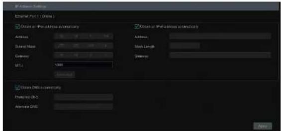
text_image
IP Address Provider Internet Provider ( Online ) Options at IP address information Address Name Gateway NET Access Options at IP address information Address Name Length Gates Options Options DNS community Preferred OK Agriptics DNS Options11.1.2 Port Conguraon
Click Start→Sengs→Network→Port to go to the interface as shown below. Enter the HTTP port, HTTPS port, server port and RTSP port of the DVR, enable "Anonymous" as needed and then click "Apply" buon to save the sengs.


text_image
Function/Pass to https □ Include Certificate Installation Certificate Installation Create a certificate Signet certificate absolutely remarkable installed directly Create a certificate required Create a certificate Create* You can create a private cercate here. Click the "Create" buon to create a private cercate. Enter the country (only two leers available), domain (DVR's IP address/domain), validity date, password, province/state, region and so on. Then click "OK" to save the sengs.
* If there is a signed cercate, click "Browse" to select it and then click "Install" to install It.
* Click "Create a cercate request" to enter the following interface.

text_image
Enable Installation type Have signed certificate, install directly Create a private certificate Create a certificate request Create a certificate request Create Download DeleteClick "Create" to create the cercate request. Then download the cercate request and submit it to the trusted cercate authority for signature. Aer receiving the signed cercate, import the cercate to the device.
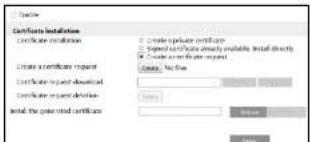
text_image
Certificate Installation Certificate installation Create certificate request Certificate request download Certificate request delete Install the selected certificate Create private certificate Select certificate directly available, install directly Create or certificate request Create, No file Save CancelDevice Management
DVR User Manual
11.1.3 PPPoE Conguraon
Click Start→Setngs→Network→PPPoE to go to the Interface as shown below. Check "Enable" In "PPPoE Setngs" and then enter the username and password obtained from the dealer. Click "Apply" to save the sengs.
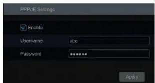
text_image
PPPoE Settings Enable Username abc Password ******** Apply11.1.4 DDNS Conguraon
The DDNS is used to control the dynamic IP address through domain name. Speco Technologies provides free DDNS service with US-based servers. You can access the DVR easily if the DDNS is enabled and congured. Click Start→Sengs→Network→DDNS to go to the interface as shown below. The default DDNS type will be "specoddns.net". The default domain name will be shown. You can use this for your domain name or enter your own. If invalid or taken, please select another domain name. Click on test to check if ok. If so, you may now go to [your domain name].specoddns.net with Internet Explorer and access your recorder remotely.
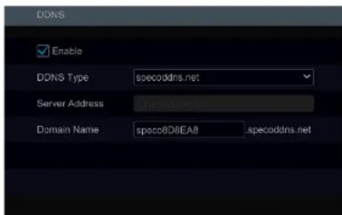
text_image
DDNS Enable DDNS Type specoddns.net Server Address E:\specoddns.net Domain Name spoco8D8EA8 .specoddns.netDevice Management
DVR User Manual
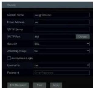
text_image
Sender Sender Name: xxx@163.com Email Address: xxx SMTP Server SMTP Port: 415 Security: SSL Attaching Image: No. Anonymous Login Username: xxx Password: Enter Password Edit Browser: Text ApplyClick "Edit Recipient" to go to the following interface.
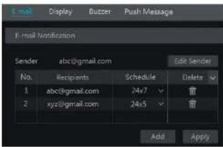
text_image
E-mail Notification Sender abc@gmail.com Edit Sender No. Recipients Schedule Delete 1 abc@gmail.com 24x7 2 xyz@gmail.com 24x5 Add ApplyClick "Add" and then enter the recipient's e-mail address and select the schedule (if a schedule is selected, the system will send the alarm email and the recipient will receive it only in the selected schedule me) in the popup window. Click "Add" in the window to add the recipient. You can also change the recipient's receiving schedule by clicking √ in the "Schedule" column. Click 📄 to delete the recipient in the list. Click "Apply"
Device Management
DVR User Manual

text_image
UPnP Enable Map Type Manual Port Type External Port External IP Address Port UPnP Status Edit HTTP Port 80 183.17.254.19 Valid UPnP HTTPS Port 443 183.17.254.19 Valid UPnP Server Port 6036 183.17.254.19 Valid UPnP RTSP Port 554 183.17.254.19 Valid UPnP Refresh Apply11.1.7 802.1X
If it is enabled, the DVR data can be protected. When the DVR is connected to the network protected by the IEEE 802.1X, user authencaon is needed.
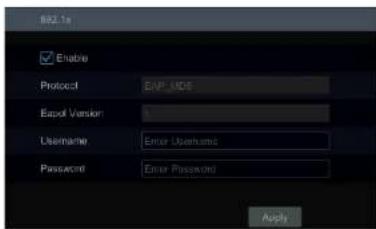
text_image
EAP.1a Enable Protocol EAP.MDS Rapid Version Username Enter Userhand Password Enter Password ApplyTo use this funcon, the DVR shall be connected to a switch supporting 802.1x protocol. The switch can be considered as an authencaon system to identify the device in a local network. If the DVR connected to the network interface of the switch has passed the authencaon of the switch, it can be accessed via the local network.
Protocol type and EAPOL version: Please use the default sengs.
Device Management
DVR User Manual
11.2 Basic Conguraon
11.2.1 General Conguraon
Click Start→Settings→System→Basic→General Settings to go to the following interface. Set the device name, device No., language, video format and main output. Enable or disable wizard, "Log In Automacally", "Log Out Automacally" (If checked, you can set the wait me), "App Live Self-Adapon" and "Sequence Automacally" (if checked, you can set the wait me). Click "Apply" to save the sengs.

text_image
General Settings Device Name Device Name Device No 1 Language English Video Format NTSC Main Output 1928x1888 Enable EZ Setup Log In Automatically Log Out Automatically Wait Time 1 Minute Spot App Live Self-adaption Sequence Automatically Wait Time 10 Minutes ApplyDevice Name: The name of the device. It may display on the client end or CMS that help user to recognize the device remotely.
Device Management
DVR User Manual
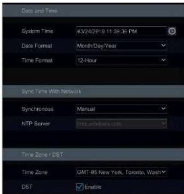
text_image
Date and Time System Time 03/24/2819 11:39:36 PM Date Format Month/Day/Year Time Format 12-Hour Sync Time With Network Synchronous Manual NTP Server time windows.com Time Zone / DST Time Zone GMT-B5 New York, Toronto, Wash DST Enable11.2.3 Recorder OSD Sengs
Click Start→Sengs→System→Basic→Recorder OSD sengs to go to the following interface. Name, icon and address OSD can be enabled here.
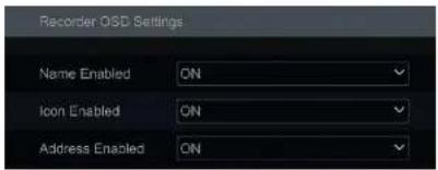
text_image
Recorder OSD Settings Name Enabled ON Icon Enabled ON Address Enabled ONDevice Management
DVR User Manual
to the path where the upgrade soware exists. Select the upgrade soware and then click "Upgrade". The system may automatically restart during upgrading. Please wait for a while and do not power o the DVR during upgrading.
Note: The file system of the USB mobile device which is used for upgrading, backing up and restoring should be PAT32 format.
- Flash Upgrade
The upgrade steps are as follows:
① Copy the ash upgrade les into the USB storage device.
② Insert the USB storage device into the USB Interface of the DVR.
③ Restart the DVR. Then the system will automacally upgrade.
11.5 Backup and Restore
You can back up the conguraon le of the DVR by exporng the le to other storage devices; you can recover the conguraon to other DVRs which are of the same model with the DVR by imporng the conguraon le to other DVRs for me saving.
Insert the USB storage device into the USB interface of the DVR and then click Start→Sengs→System→Maintenance→Backup and Restore to go to the interface.
- Backup
Select the USB device in "Device Name" opon; go to the path where you want to store the conguraon backup le and then click "Backup" buon; nally click "OK" buon in the popup window.
- Recover
Select the USB device in "Device Name" opon; nd the conguraon backup le and then click "Recover" buon; nally click "OK" buon in the popup window.
Device Management
DVR User Manual
11.7 View Log
Click Start→Sengs→System→Maintenance→View Log to go to the log view interface. Select the log main type, click set start me and end me and then click "Search" buon. The searched log les will be displayed in the list.
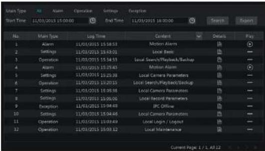
text_image
Main Type Start Time 11/03/2015 15:00:00 All Alarm Operation Settings Exception End Time 11/03/2015 16:00:00 Search Export No Main Type Log Time Content Details Play 1 Alarm 11/03/2015 15:58:53 Motion Alarm (%) 2 Settings 11/03/2015 15:43:01 Local Basic (%) 3 Operation 11/03/2015 15:34:51 Local Search/Playback/Backup (%) 4 Alarm 11/03/2015 15:25:43 Motion Alarm (%) 5 Settings 11/03/2015 15:25:38 Local Camera Parameters (%) 6 Operation 11/03/2015 15:20:15 Local Search/Playback/Backup (%) 7 Settings 11/03/2015 15:05:38 Local Camera Parameters (%) 8 Settings 11/03/2015 15:05:00 Local Record Parameters (%) 9 Exception 11/03/2015 15:04:48 IPC Online (%) 10 Settings 11/03/2015 15:04:46 Local Camera Parameters (%) 11 Operation 11/03/2015 15:03:49 Local Login / Logout (%) 12 Operation 11/03/2015 15:03:12 Local Maintenance (%) Current Page 1 / L A# 12Choose the log le in the list and then click "Export" buon to export the log le. Click on the "Content" tle bar to pop up a menu list. Check contents in the menu list and then the log list will show the checked log contents only. Click to play the video log.
11.8 View System Informaon
Click Start→Setngs→System→Informaon and then click the corresponding menu to view the "Basic", "Camera Status", "Alarm Status", "Record Status", "Network Status" and "Disk" information of the system.
12 Remote Surveillance
12.1 Mobile Client Surveillance
① Enable NAT in the DVR. Refer to 11.1.8 NAT Conguraon for details.
② Scan the QR Code through the Speco Blue App available for IOS and Android to easily and securely view your cameras.
⑧ Run the mobile client, go to the "Add Device" Interface and then click □ to scan the QR Code of the DVR (Go to Start→Settings→System→Informaon→Basic to view the QR Code of the DVR).
④ Aer scanning the QR Code successfully, enter the login password to log in mobile client.

text_image
Add Device Preview OR Code Scanning Add OR code scanning version to scan12.2 Web LAN Access
① Click Start→Sengs→Network→TCP/IP to go to the "TCP/IP" interface. Set the IP address, subnet mask, gateway, preferred DNS and alternate DNS of the DVR.
② Open the web browser on your computer, enter the IP address of the DVR in the address bar and then press enter to go to the login interface as shown below. You can change the display language on the top right corner of the login interface. Enter the username and password of the DVR in the interface and then click "Login" to go to the live view interface.
12.3 Web WAN Access
① Set the network of the DVR. Please refer to 11.1.1 TCP/IP Conguraon for details.
② Click Start→Sengs→Network→NAT to go to the interface for NAT congraraon and check "Enable". Click "Apply" to save the sengs and make note of the QR code number under the QR code. Via Internet Explorer, go to connect.specotech.cloud, input the QR code number, your username and password to login.

text_image
speco technologies Giving You More.> PPPoE Access
① Click Start→Settings→Network→PPPoE to go to the "PPPoE" interface. Check "Enable" in the "PPPoE sengs" and then enter the username and password you get from your ISP. Click "Apply" to save the sengs.
② Click Start→Sengs→Network→Network Status to view the IP address of the DVR.
③ Open the web browser on your computer, enter the IP address of the DVR like hp://210.21.229.138 in the address bar and then press enter to go to the login interface. Enter the username and password of the DVR in the interface and then click "Login" to go to the live view interface.
Router Access
① Click Start→Sengs→Network→TCP/IP to go to the "TCP/IP" interface. Set the IP address, subnet mask, gateway, preferred DNS and alternate DNS of the DVR.
② Set the HTTP port (it is suggested to modify the HTTP port because the default HTTP port 80 might be taken up) and enable UPnP funcon in both the DVR and the router. If the UPnP funcon is not available in the router, you need to forward the LAN IP address, HTTP port and server port of the DVR to the router. Port mapping settings may be dierent in different routers, so please refer to the user manual of the router for details.
Remote Surveillance
DVR User Manual
admin: the current login username.
Logout: click it to log out and return to the login interface.
Modify Password: click it to change the password of the current login user. Enter the current password and then set a new password in the popup window. Click "OK" buon to save the new password.
Local Sengs: click it to change the local sengs. Set the snapshot number and click "Browse" to set the snapshot path and record path as shown below. Click "Apply" buon to save the sengs.

text_image
Snapshots number Save snapshots to: C:\UserslyPictures Browse Save result files to: C:\UserslyVideos Remove Apply12.4.1 Remote Preview
Click "Live View" in the remote interface to go to the live view interface. The live view interface consists of the four areas marked in the following picture,

text_image
ESPECO Technologies Live Time Playback Export Settings C:\Users\AD/102\Control\Control\Control\Control\Control\Control\Control\Control\Control\Control\Control\Control\Control\Control\Control\Control\Control\Control\Control\Control\Control\Control\Control\Control\Control\Control\Control\Control\Control\Control\Control\Control\Control\Control\Control\Control\Control\Control\Control\Control\Control\Control\Control\Control\Control\Control\Control\Control\Control\Control\control C:\Users\AD/102 Control Control Control Control Control Control Control Control Control Control Control Control Control Control Control Control Control Control Control Control Control Control Control Control Control Control Control Control Control Control Control Control Control Control Control Control Control Control Control Control Control Control Control Control Control Control Control Control Control Control C:\Users\AD/102\control C:\Users\AD/102\controlRemote Surveillance
DVR User Manual
3 in Camera (3/4) on the le panel stands for the number of online cameras; the right number 4 stands for the number of all the added cameras. Enter the camera name in the search box and then click to search the camera. Click to refresh the camera list.
• View Scheme
Click Customize Layout to view the scheme (or planning). All schemes can be shown in the ie panel. Double click the scheme name to invoke it quickly
Tool Bar Introducon
| Buon | Meaning | |
| Screen mode buon. | ||
| Click it to disable OSD. Clickto enable OSD. | ||
| Click it to show full screen. Right click on the full screen to exit full screen. | ||
| All Main Stream | All Sub Stream | Click "All Main Stream" or "All Sub Stream" to set the stream of all the cameras. |
| Manual alarm buon. Click it to pop up a window and then trigger and clear the alarm-out in the window manually. | ||
| Click it to preview all cameras. | ||
| Click it to close all the preview cameras. | ||
| Click it to start recording for all cameras to computer. Clickstop recording. | ||
| Click it to start manual record for all cameras to the DVR. Clickstop manual record for all cameras. | ||
| Click it to enable talk with the DVR. | ||
Right Panel Introducon
Click < on the right panel to show the panel and click > to hide the panel. Click PTZ at the boom of the panel to go to "PTZ" panel. Click 📄 to go to "Lens Control". Click Operation to go to "Operaoon" panel.
Remote Surveillance
DVR User Manual

text_image
Operation FTZ Zoom Control Operation Zoom Control FTZOperaon panel introducon:
| Buon | Meaning |
| Click it to take snapshots. | |
| Click it to start recording to computer; click it again to stop recording. | |
| Click it to zoom in the image of the camera and then drag the mouse on the camera image to view the hidden area. | |
| Click it to zoom out the image of the camera. | |
| The 3D zoom in funcon is designed for P.T.Z. Click it and then drag the image to zoom in or zoom out the image; click the image on different areas to view the image of the | |
| Click [√No zodirin/out camera image. | |
| Click [√to increase/decrease the focal length. | |
| Click [√to increase/decrease the iris of the dome. | |
| Click it to view the preset list and then click the buon in the list to call the preset. | |
| Click it to view the cruise list and then click the corresponding buons in the list to start or stop the cruise. |
12.4.2 Remote Playback
Click "Playback" in the remote interface to go to the playback interface.
① Check the record event types and cameras on the le panel. Set the record date on the calendar beside the me scale.
② Click 🔍 to search the record data and then click 🔍 or directly click the me scale to play the record.
The operaon of the playback me scale is similar to that of the me scale in the main program of the DVR. Please refer to 8.2 Playback Interface ____. Introducon for details.
Introducon of playback control buons:
| Buon | Meaning |
| Stop buon. | |
| Rewind buon. Click it to play video backward. | |
| Play buon. Click it to play video forward. | |
| Pause buon. | |
| Deceleration buon. Click it to decrease the playing speed. |
Remote Surveillance
DVR User Manual
Event Search
Check the record type on the le side of the interface and then click to set the start me and end me; check the cameras and then click on the right side to search the record (the searched record data will be displayed in the list); check the record data in the list and then click "Export" buon to export the record.
Time Search
Click to set the start me and end me on the le side of the interface; check the cameras and then click on the right side to backup the record.
Snapshots
The system will display all the captured images automatically in the list. Click to delete the image. Click to pop up the "Export" window. Click to pop up the "View Image" window. Click to export the image.
View Export Status
Click "Export Status" to view the export status. Click "Pause" to stop the export; click "Resume" to connue the export; click "Delete" to delete the task.
12.4.4 Intelligent Analysis
Click "Intelligent Analysis" in the remote interface to congure smart search, stascs, target database, face aendance and face check in. All of these sengs are similar to that of the DVR. See the conguraons of the DVR for details.
12.4.5 Remote Conguraon
Click "Funcon Panel" in the remote interface and then congregate the camera, record, alarm, disk, network, account and authority and system of the DVR remotely. All of these sengs are the same as the sengs of the DVR. See the conguraons of the DVR for details.
Appendix A FAQ
Q1. Why can't find the HDD?
a. Please check the power and SATA data cables of the HDD to make sure they are well connected.
b. For some DVRs with the 1U or small 1U case, the power of the adapter may be not enough for operating them. Please use the power adaptor supplied along with the DVR.
c. Please make sure the HDDs are compatible with the DVR. See Appendix C Compatible Device List for details.
d. The HDD could have gone bad.
Q2. Why are there no images output in some or all of the camera windows?
a. Please make sure the resolutions of the cameras are supported by the DVR.
b. Please make sure the network cables of the IP camera and DVR are both connected properly and the network parameters are set correctly.
c. Please make sure the analog camera is connected properly.
d. Please make sure the network and the switch both work normally.
Q3. The screen has no output aer boong the DVR normally.
a. Please make sure the screen, HDMI or VGA cables are good and well connected.
b. Please make sure the screen supports the resoluon of 1280*1024, 1920*1080 or 3840*2160 (4K*2K). The DVR cannot self-adapt to the screen of which the resoluon is lower than 1280*1024, and then the screen will remind you that the screen resoluon is not supported by the DVR or just have no display. Please change a screen at 1280*1024, 1920*1080 or 3840*2160 resoluon before boong the DVR.
Q4. Forget your passwords?
a. The password for admin can be reset through "Edit Security Question" funcon.
Click "Edit Security Queson" buon in the login window and then enter the corresponding answer of the selected queson in the popup window, the password for admin will be reset. If you forget the answer of the queson, this way will be invalid, please contact your dealer for help.
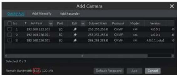
text_image
Add Camera Quality Add Add Manually Add Recorder No Address Port Edit Subnet Mask Protocol Model Version 1 192.168.122.103 80 255.255.255.0 ONMF xxx 4.0.0.1 0 2 192.168.226.201 80 255.255.255.0 ONMF xxx 4.0.0.1 0 3 192.168.226.201 80 255.255.255.0 ONMF xxx 4.0.0.1 beta1 0 Selected: 0 / 3 Remain Bandwidth: 100 / 120 Mb Default Password Add CancelQ6. The system cannot record, why?
a. Make sure the HDD was formed prior to use.
b. The record schedule has not been set in manual record mode. Please refer to 7.3.2 Record Schedule Conguraon for details.
c. Maybe HDD is full and thus the DVR is not able to record. Check HDD informaon from Disk Management and if required, please enable the recycle funcon (please see 7.1.2 Advanced Conguraon for details).
d. There is no disk but cameras in the disk group, so please add at least one disk to the group. Refer to 7.5.1 Storage Mode Conguraon for details.
e. The HDD could have gone bad. Please contact tech support.
Q7. Fail to access the DVR remotely through IE.
a. Please make sure the IE version is IE8 or above.
b. Please check whether the PC has enabled the rewall or installed the anvirus soware. Please try to access the DVR again aer you disable the rewall and stop the anvirus soware.
c. Allow & block list may have been set in Account and Authority seng. The PC of which the IP address is in the block list or out of the allow list cannot access the DVR remotely.
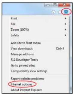
text_image
Print File Zoom (100%) Safety Add site to Start menu View downloads Ctrl+J Manage add-ons F12 Developer Tools Go to pinned sites Compatibility View settings Report website problems Internet options About Internet Explorer② Select Security→Custom Level. Refer to Fig 10-1.
③ Enable all the sub opons under "AcveX controls and plug-ins". Refer to Fig 10-2.
① Then click "OK" to nish setup.
b. Other plug-ins or an-virus may block AcveX. Please disable or do the required sengs.
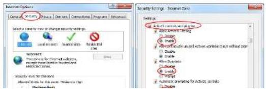
text_image
Internet Options General Options Private (Domains) Consultative Programs (Enhanced) Select a zone to view or change security settings Local settings / Resources Security Settings - Internet Zone Settings 4.0.4.1.1.2.3.4.5.6.7.8.9.10.11.12.13.14.15.16.17.18.19.20.21.22.23.24.25.26.27.28.29.30.31.32.33.34.35.36.37.38.39.40.41.42.43.44.45.46.47.48.49.50.51.52.53.54.55.56.57.58.59.60.61.62.63.64.65.66.67.68.69.70.71.72.73.74.75.76.77.78.79.80.81.82.83.84.85.86.87.88.89.90.91.92.93.94.95.96.97.98.99. Interoper This service is for Internet availability, except those listed in location and restricted areas. Security Level for the zone Allowed sites for the zone to be taken in the Networks section Allowing access to the zone to the Networks section Allowing access to the zone to the Networks section Allowing access to the zone to the Networks section Allowing access to the zone to the Networks section Allowing access to the zone to the Networks section Allowing access to the zone to the Networks section Allowing access to the zone to the Networks section Allowing access to the zone to the Networks section Allowing Access to the zone to the Networks section Allowing Access to the zone to the Networks section Allowing Access to the zone to the Networks section Allowing Access to the zone to the Networks section Allowing Access to the zone to the Networks section Allowing Access to the zone to the Networks section Allowing Access to the zone to the Networks section Allowing Access to the zone to the Networks sectionsSelect camera in the resource tree on the le side of the interface to play the camera record. Click enable audio. Refer to Fig 11-2.

n the tool bar under the camera image to
Note: The record will not have audio output if you disable the audio when recording by DVR. Please see 7.1.1 Mode Configuration and 7.2 Encode Parameters Setting for details.
- If you select the AVI format when backing up recorded video by DVR, the recorded video can be played by the video player which supports this format.
b. Recorded video backed up through web. The recorded video can only be backed up with AVI format through web. The recorded video can be backed up to PC and played by the video player which supports this format.

text_image
RPAS Play List + - RPAS Open Folder CPU 65% RATM 40% 2016/7/30 3:00:00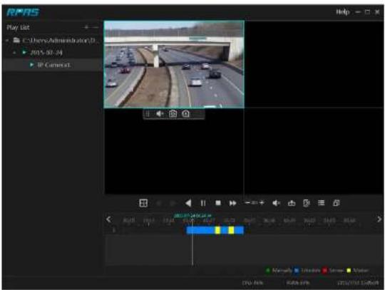
text_image
RPAS Play List C:\CherryAdministration\D 2015-07-34 IP Cametat 2015-07-34 2015-07-34 2015-07-34 2015-07-34 2015-07-34 2015-07-34 2015-07-34 2015-07-34 2015-07-34 2015-07-34Fig 11-2
Appendix B Calculate Recording Capacity
The recording capacity is mainly up to the record resoluon, record stream and bitrate. Dierent image quality parameters decide dierent disk capacity occupa on in equal mes. The bigger the record resoluon, record stream and record bitrate is, the more disk capacity is taken up in equal mes. The calculaon format of recording capacity is shown as below.
Recording Capacity(MB) = Bitrate(Kbps) ÷ 1024 ÷ 8 × 3600 × Recording hours per day × Record Storage Days × channel numbers
3600 means record for an hour(1TB=1024GB, 1GB=1024MB, 1MB=1024KB, 1Byte=8bit).
| Record Bitrate (Kbps) | Used Space (MB/H) | Used Space (MB/D) |
| 10240 | 4500 | 108000 |
| 8192 | 3600 | 86400 |
| 6144 | 2700 | 64800 |
| 4096 | 1800 | 43200 |
| 3072 | 1350 | 32400 |
| 2048 | 900 | 21600 |
| 1024 | 450 | 10800 |
| 768 | 337.5 | 8100 |
| 512 | 225 | 5400 |
| 384 | 168.75 | 4050 |
| 256 | 112.5 | 2700 |
The table below shows the recording capacity requirements for record storage in 30 days.
| Record Bitrate [Kbps] | Recording Capacity (TB) | |||||
| 1CH | 4CH | 8CH | 16CH | 32CH | 64CH | |
| 10240 | 3.09 | 12.36 | 24.72 | 49.44 | 98.88 | 197.76 |
Appendix C Specicaons
| Model | H6HRL | H16HRL | H24HRL | |
| System | Compression | Standard H.265 | ||
| OS | Embedded Linux | |||
| Video | Analog Input | BNC x4 | BNC x8 | BNC x16 |
| IPC Input | 2CH (up to 6CH)* | 8CH (up to 16CH)* | 8CH* | |
| Network Access & Transfer Bandwidth | 16/40Mbps | 32/96Mbps | 64/192Mbps | |
| Network Access Format | 8MP/5MP/4MP/3MP/1080P/960P/720P@25/30fps | |||
| Output | HDMI×1: 4K×2K/1920x1080/1280×1024.VGA×1: 1920x1080/1280×1024/1024×768BNC×1: CVBS (used as the main or spot output) | |||
| Audio | Input | RCA×4 | RCA×8 | RCA×8 |
| 2-way Audio | Take up channel one audio input | |||
| Local Output | RCA×1 | |||
| Record | Record Stream | Dual stream recording | ||
| Resoluon | 4K/5MP/4MP/1080P/720P/WD1 | |||
| Frame Rate | 4K@6fps/7fpsSMP@12fps (PAL/NTSC)4MP@12fps/15fps (PAL/NTSC)1080P/720P/WD1@25fps/30fps (PAL/NTSC) | |||
| Bit Rate | 32~8Mbps | |||
| Mode | Manual, schedule, moon, sensor, intelligence | |||
| IP Input | Resoluon | 8MP/5MP/4MP/3MP/1080P/960P/720P@25fps/30fps | ||
| Playback | Simultaneous Playback | Max 4 CH | Max 8 CH | Max 16 CH |
| Search Mode | EZ search, museum search, me search, event search, bookmark search, snapshot search | |||
| Smart Search | Highlighted color to display camera records in a certain period of me, dierent colors refer to dierent record events | |||
Specicaons
DVR User Manual
| Network | Yes | |||
| Interface | USB | USB2.0×2 | ||
| Remote Controller | Yes | |||
| Others | Power Supply | DC12V/2A | DC12V/4A | DC12V/4A |
| Power Consumpon | ≤10W (without HDD) | ≤15W (without HDD) | ≤30W (without HDD) | |
| Dimensions(W×D×H) | 11.8" x 9.8" x 1.8"(300mm×248mm×45mm) | 15" x 10.6" x 1.8"(380mm×268mm×45mm) | 15" x 10.6" x 1.8"(380mm×268mm×45mm) | |
| Working Environment | -4~122F (-10~50°C), 10%~90% (humidity) | |||
Note:
* 6HRL can convert all analog channels into IP input, so its total IP input is 6ch;16HRL can convert all analog channels into IP input, so its total IP input is 16ch; H24HRL can convert the last B analog channels into IP input, so its total IP input is 16ch.
Android is a trademark of Google LLC.
Model: H6HRL/H16HRL/H24HRL
Federal Communicaons Commission (FCC) Statements
This device complies with Part 1S of the FCC Rules. Operaon is subject to the following two conditions: (1) This device may not cause harmful interference, and (2) This device must accept any interference received, including interference that may cause undesired operaon.
FCC Responsible Party:
Speco Technologies
200 New Highway
Amityville, NY 11701
www.specotech.com