OPTZ36XI - Security Camera Speco Technologies - Free user manual and instructions
Find the device manual for free OPTZ36XI Speco Technologies in PDF.

User questions about OPTZ36XI Speco Technologies
0 question about this device. Answer the ones you know or ask your own.
Ask a new question about this device
Download the instructions for your Security Camera in PDF format for free! Find your manual OPTZ36XI - Speco Technologies and take your electronic device back in hand. On this page are published all the documents necessary for the use of your device. OPTZ36XI by Speco Technologies.
USER MANUAL OPTZ36XI Speco Technologies
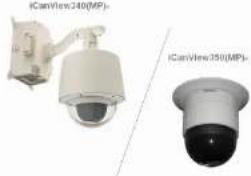
ONSIP OPTZ36XO ONSIP OPTZ36XI

natural_image
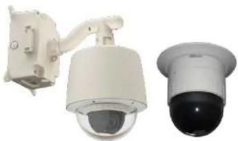
Two white speco technologies security cameras on a metal diamond-patterned surface (no visible text or symbols on the cameras themselves)Revision History
| Date | Rev No. | Description |
| 2011-11-01 | 1.0 | First manual revision creation. |
Warning & Cautions
If you fail to read this information and handle the product incorrectly, faulty or malfunction as well as death or serious injury may occur.
This Unit should be installed by trained personnel.
Immediately stop using when the product emits smoke or abnormal heat.
Never install the product in area exposed to oil or gas.
Never install the product on a ceiling that cannot hold its weight.
Never touch the power cord with wet hands.
Clean only with dry cloth.
text_image
CAUTION RISK OF ELECTRIC SHOCK DO NOT OPEN ! CAUTION: TO REDUCE THE RISK OF ELECTRIC SHOCK. DO NOT REMOVE COVER (OR BACK). NO USER SERVICEABLE PARTS INSIDE. REFER SERVICING TO QUALIFIED SERVICE PERSONNEL
text_image
This symbol is intended to alert the user to the presence of un-insulated 'dangerous voltage' within the product's enclosure that can cause electric shock. This symbol is intended to alert the user to the presence of important operating and maintenance (servicing) instructions in the literature accompanying the appliance.Indications:

Warning: Death or Serious Injury will occur without following Warning.
Caution : Operational Problem(Faulty & Malfunction) will occur without complying with Caution
Reference : Technical Information for Users
Table of Contents
Table of Contents....5
- Introduction....7
1.1. Overview of ONSIP OPTZ36XO/I 7
1.2. Specification....8
1.2.1. Basic Specification 8
1.2.2. Detailed Specification of Camera Module & PTZ
1.2.3. Basic Specification
1.2.4. Detailed Specification of Camera Module
1.3. Application of ONSIP OPTZ36XO/I 9
- Production Description.... 10
2.1. Package Contents ...... 10
2.1.1. ONSIP OPTZ36XO....10
2.1.2. ONSIP OPTZ36XI 10
2.2. Preview 11
2.3. Physical Description 12
- Installation 28
4.1. Required System Specification 28
4.2. Quick Installation Guide 29
- Trouble Shooting 35
5.1. No Video on Viewer....35
5.2. Windows vista and Windows 7 User for Record & Capture Problem ..... 36
5.3 Technical Inquiry.... 39
- Appendix 40
6.1.FAN & Heater 40
6.2. DIP Switch Setting 42
1. Introduction
1.1. Overview of ONSI P OPTZ36XO/I
ONSIP OPTZ36XO/I, as a state-of-the-art 1Channel Speed Dome Network Camera based on integrated Embedded Software technologies such as H.264 & MJPEG, G.726 & PCM Video & Audio Compression, Embedded Web Server, Embedded Streaming Server, various Network Protocols, transmits synchronized video and audio data in real time through IP Network as well as supports bi-directional audio communication by allowing transmission of audio from Client PC to ONSIP OPTZ36XO/I.
ONSIP OPTZ36XO/I, with completed Integration with analog CCTV camera, Digital and network technology, is applicable for various sectors such as Security, Remote Monitoring, Remote Education, Simple Video Conference as well as Internet Broadcasting System etc.
1.2. Specification
1.2.1. Basic Specification
| Class | Description | ||
| Video | Compression | H.264 / MJPEG | |
| Resolution | **Refer to the datasheet | ||
| Audio(Bi-directional) | Up Stream | 32 Kbps G.726 | |
| Down Stream | 64 Kbps PCM | ||
| Network | Interface | RJ-45, 10/100 Mbps | |
| Access Network | Static, DHCP, PPP/PPPoE | ||
| Protocol | IPv4/6, TCP, UDP, IGMP, ICMP, ICMPv6 etc. | ||
| I/O | Sensor | 4 | NC, NO Selectable |
| Relay Output | 2 | Alarm or Remote ON/OFF Control (30V, 1A) | |
| RS-232C | Factory Default | ||
| Mic/Line In | Selectable on Admin Page | ||
| Line Out | 1 V p-p Audio Output for Amp embedded Speaker | ||
| CVBS Output | Supported | ||
| Power | PoE | Supported | |
| AC In | 12VDC Adaptor (higher than 2 Amp) | ||
| Housing | Water-Proof | IP66 | |
| Heater | Refer to Installation Configuration | ||
| Installation Type | Bracket | Wall, Ceiling, Ceiling Embedded Type | |
1.3. Application of ONSIP OPTZ36XO/I
- Security Surveillance (Building, Stores, Manufacturing Device, Parking Lot, Bank, Public Office & Military etc)
- Remote Monitoring (Hospital, Kindergarten, Traffic Status, Public Area)
- Video Conference, Remote Lecture, Internet Broadcasting
- Climate & Environment Surveillance
2. Production Description
2.1. Package Contents
Open the package and check if the followings are included;
2.1.1. ONSIP OPTZ36 XO
| Contents | Description | Remark |
| Bracket & Housing | Outdoor Housing, Wall Mount Bracket | |
| Accessories | Screw (M4x15 4EA), Safety Cable | |
| Manual | Housing Installation Manual | |
| IP Camera | Camera body | |
| Tools & Accessories | Wrench, Safety Cable, Cable Tie, Terminal Block(2Pin, 3Pin, 5Pin, 6Pin: 1EA), Screw(∅ 3x6 2EA,∅ 4x16 5EA) | |
| CD | Software & Product User Manual | |
| Quick Reference | Quick Installation Guide |
2.2 Preview
| ONSIP OPTZ36XO/I | IP-Installer | CMS Software(Speco-NVR) |
 |  |  |
| Speed Dome Network Camera | IP Assignment Program | PC based Client formonitoring/storing Video/Audiotransmitted form Product(Max. 64CH supported) |
2.3. Physical Description
2.3.1. External View
natural_image
Two security cameras shown from different angles (no text or symbols visible)Fig 2-1. External View of ONSIP OPTZ36XO/I
2.3.2. Bottom View & Connection Diagram
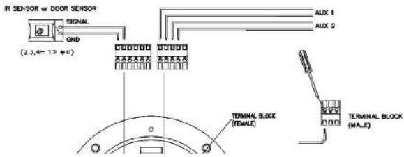
text_image
IR SENSOR or DOOR SENSOR SIGNAL GND (2,3,4=12*0) AUX 1 AUX 2 TERMINAL BLOCK (FEMALE) TERMINAL BLOCK (MALE)ONSIP OPTZ O/I Users' Guide
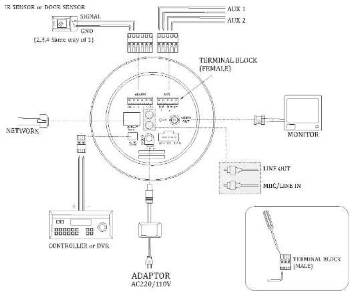
text_image
IR SENSOR or DOOR SENSOR SIGNAL GND (2,3,4 Same way of 1) AUX 1 AUX 2 NETWORK TERMINAL BLOCK (FEMALE) MONITOR LINE OUT MIIC/LINE IN CONTROLLER or PVR ADAPTOR AC220/110V TERMINAL BLOCK (MALE)Fig 2-2-2. Terminal Block, LAN & Power Connector
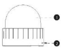
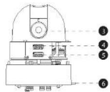
2.3.3. External & Internal View

1.Bubble
2. Lock Screw
3.DIP Switch 1
4.DIP Switch 2
5. Camera Lens
6. Lock Holder
7.Aux
8. Alarm
9.Power LED
10.LAN (100 Base-T)
11.Video Out
12.Power(AC24V)
13.RS485
14.MIC/Line IN
15.Line Out
Fig 2-3-1. Connector Part
text_image
Technical diagram of a mechanical device with numbered annotations pointing to internal components.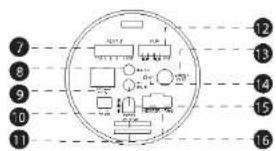
text_image
Diagram of a circular device with numbered components and internal layout, likely for electronics or system labeling.- Bubble
- Lock Screw
- Camera
- Dip Switch1
- Dip Switch2
- Lock Holder
-
Alarm
-
LAN (100 Base-T)
- RS-485 (D+, D-)
- Power Input (DC12V)
- Aux
- Video out (Analog CVBS)
- Power LED
- Mic / Line In
10.5
text_image
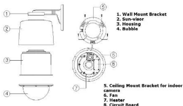
1. Wall Mount Bracket 2. Sun-visor 3. Housing 4. Bubble 5. Ceiling Mount Bracket for indoor camera 6. Fan 7. Heater 8. Circuit BoardFig 2-4. Outdoor Housing
2.4. Functional Description
- AC Power
Connect 24 Volt AC adaptor to this terminal for supplying power to the network camera.
- DC Power
Connect 12 Volt DC adaptor to this terminal for supplying power to the network camera.
- Status LED (Dual Color - Red/Green): It will be lit in green or red depending on the status.
① Green: Green color indicates that the camera is in normal operation mode. Continuous green indicates that data transmission is possible. Blinking green means that someone is connected to ONSIP OPTZ36XO/I.
② Red: Continuous or blinking red indicates that hardware is in abnormal condition.

Red/Green LED will be lit with red momentarily and it will be lit with green after a while when power is applied into ONSIP OPTZ36XO/I.
LINK/LAN LED (Orange): It will be lit with orange color when network cabling is all right. Blinking orange color indicates that normal data transmission is under way. Off state indicates that there is trouble in network connection.
• HEATER/FAN
Used for connecting power cable of heater and fan. Power cable of heater and fan is in the bracket.
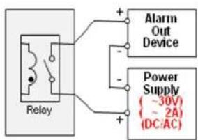
• Alarm In/Out (ALARM/AUX)
Used for connecting alarm sensor, alarm annunciation device to ONSIP OPTZ36XO/I.
| Class | Description |
text_image
Relay + - Alarm Out Device Power Supply (-30V) (~2A) (DC/AC)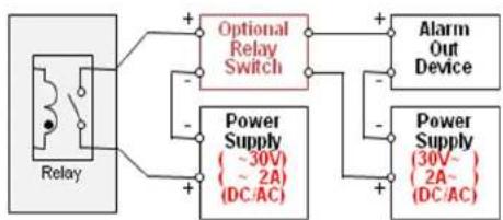
flowchart
graph LR
    A["Relay"] --> B["Optional Relay Switch"]
    A --> C["Power Supply (30V ~ 2A) (DC/AC)"]
    B --> D["Alarm Out Device"]
    C --> E["Power Supply (30V ~ 2A) (DC/AC)"]
    D --> F["+"]
    E --> G["+"]
    F --> H["+"]
    G --> I["-"]
    H --> J["-"]
    I --> K["+"]
    J --> L["-"]
Fig 2-5. Relay Connection Diagram (Left: lower than 30V, 2A, Right: Higher than 30V 2A)
- Alarm
Connect external alarm sensor. Examples of sensing devices are infrared sensor, motion sensor, heat/smoke sensor, magnetic sensor, etc. Connect the two wires of the sensors to "SNS In". The sensor type (NC/NO) can be set in admin page. 10mA can be flown into sensor device. Multiple sensor devices can be connected in parallel.

text_image
Photo Coupler +12V GND Sensor1+ Sensor1- Sensor1- NO/NCType Sensor Device + - Open CollectorType Sensor Device -3. Bracket Installation
3.1. ONSIP OPTZ36XO
3.1.1. Basic Components & Mounting Accessories

text_image
Diagram of a spray gun with labeled parts 1 and 2
text_image
5 1 2 3 4 6 8 7 5. Ceiling camera- Wall Mount Bracket
- Sun-viso
- Housing
- Bubble


- Ceiling Mount Bracket for indoor
camera
- Fan
- Heater
- Circuit Board
3.1.2. Preparation
- Configure the DIP Switch by referring Appendix.
DIP Switches : Make sure to set the switch positions as illustrated below.
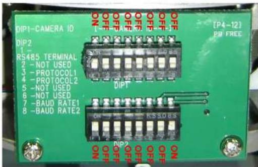
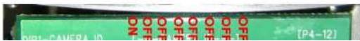
text_image
DIP1-CAMERA ID DIP2 RS485 TERMINAL 2 - NOT USED 3 - PROTOCOL1 4 - PROTOCOL2 5 - NOT USED 6 - NOT USED 7 - BAUD RATE1 8 - BAUD RATE2 [ P4-12 ] PP FREE OFF OFF OFF OFF OFF OFF OFF OFF OFF OFF OFF OFF DIPT OFF OFF OFF OFF KSS08S ON ON
- When using system controller for the control of the dome, always set the RS-485 communication channel to be: 2400 bps, 8 bit, 1 stop bit, no parity.
- Place the Dome Cover and screw.
Placing Dome Cover
3.1.3. Installation using Walling Mount Type
The wall should be strong enough to hold 4 times of the weight of the camera (5.3 KG). This means that the wall should withstand weight of 21.2 KGs in the minimum.
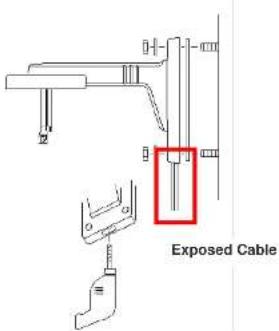
- Pass the combined cable through the inside Cable Gland.

text_image
CABLE GLAND COMBINED CABLE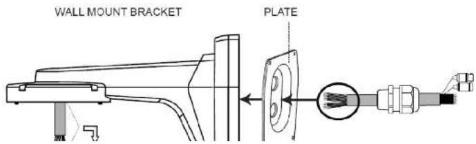
text_image
WALL MOUNT BRACKET PLATE
text_image
Technical diagram showing a mechanical assembly with labeled components and a highlighted section in red.Hidden Cable
text_image
Exposed Cable- Connect Sun-Visor with Wall Mounting Bracket. (1)
- After connecting Product and Cable, install the product by inserting Product into internal fixing hole of housing and turning in clockwise. (2)
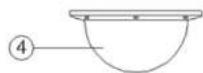
- Assemble the Bubble. (3)
1

2
3

3.2 ONSIP OPTZ36XI
3.2.1. Preparation
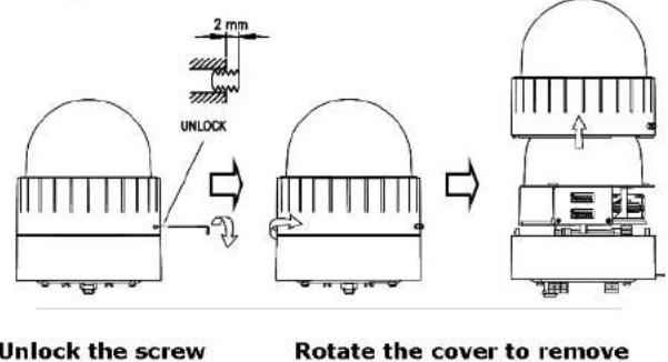
- Open the Dome Cover by unscrewing with wrench.
Opening Dome Cover
text_image
2 mm UNLOCK Unlock the screw Rotate the cover to remove- Configure the DIP Switch by referring Appendix.
DIP Switches : Make sure to set the switch positions as illustrated below.
- Place the Dome Cover and screw.
Placing Dome Cover

text_image
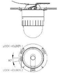
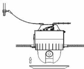
Place the cover & rotate to tighten Lock the screw Screw head should be even with the surface when locked. LOCK3.2.2. Installation using Ceiling Mount Type

Ceiling board should be strong enough to hold the weight of approx.. 2Kg.
5 Attach the CAMERA to the CEILING MOUNT. TO attach the CAMERA to the CEILING MOUNT, insert the CAMERA MOUNT HOLES
Into the BRACKET MOUNT HOLES and twist the camera by 10° toward locked position.
text_image
LOCK HOLDER NC LOCK HOLDER-2
text_image
6 Place M3 screw to fix the CAMERA. SW (M3.0)
text_image
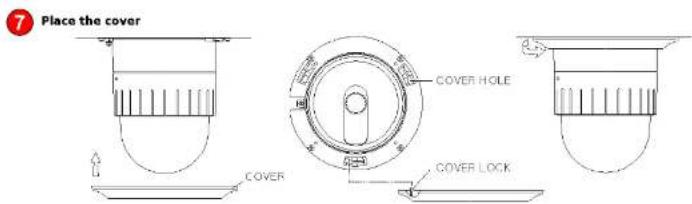
Place the cover COVER HOLE COVER COVER LOCK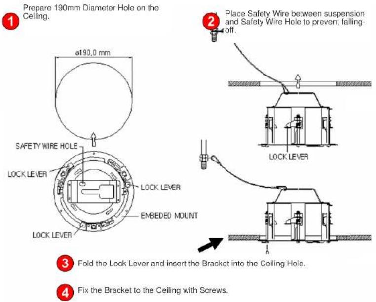

text_image
5 Insert the CAMERA into the MOUNT.
text_image
6 APPLY screw to fix the CAMERA. - SCREW (M3.0)7 Place the COVER to finish the installation
natural_image
Technical line drawing of a mechanical device with no visible text or symbols4. Installation
4.1. Required System Specification
Required Specification of PC for Camera Configuration & Control.
| Class | Recommendation | Remark |
| CPU | Pentium-4 3Ghz | |
| RAM | 1GB | |
| Graphic Card | Higher than ATI Chip-Set based 64M | 1600x1200(UXGA) |
| LAN Card | Higher than 100Mbps | |
| OS | Windows XP | |
| Web Browser | Higher than Internet Explorer 6.0 |
** Operating Systems supported: Windows 2000 Professional, Windows XP / Vista / 7
4.2. Quick Installation Guide
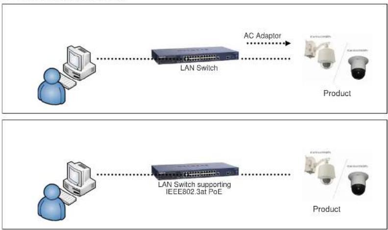
flowchart
graph LR
    A["Person"] --> B["LAN Switch"]
    B --> C["AC Adaptor"]
    D["Person"] --> E["LAN Switch supporting IEEE802.3at PoE"]
    E --> F["Product"]
Fig 4-1. LAN Cable Connection Diagram
1. Connect PC and ONSIP OPTZ36XO/I to Network Device (HUB)
I. Prepare a PC which needs to be connected to Network.
ONSIP OPTZ O/I Users' Guide

text_image
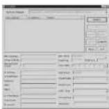
Admin Page Button IP installerFigure 4-2. Speco-NVR
Follow the sequence below for setting the IP parameter
i) Run IP installer
ii) Click ① in IP installer window.> Double click on ② > Fill in ④ > make a selection in ⑤ > Fill the parameters in ⑥
iii) Click on ⑨ to apply the settings.
ONSIP OPTZ O/I Users' Guide

text_image
IP Installer MAC Address IP Address Name No Refresh Set Admin Pass Reload Default Adapter About Exit MAC Address System Name Management Server UPnP Disable UPn Static ADSL(PPPqE) Auto(DHCP) WLAN SSID Auth. Type EncryptType WLAN Key Network Adapter WDewwwMPP_14580157E-SF24-MAC 1-B382-PE0573-EFAB Net Mode Static Web Port RTSP Port Clone MAC IP Address Subnet Mask Gateway DNS1 DNS2 Service Name User Name Password
Click on the field in ③ for sorting and rearranging the list.
Select network mode that best suits from the drop down list in ⑤. You can choose either
3. Remote Connection to IP Camera
I. Connection via Web Viewer
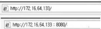
Web View is the simplest method to connect to product via internet explorer. Once you insert "http://IP_address:HTTP_port_number" into Internet Explorer, you can access to the relevant product.

For the use of Web Viewer, Active-X module should be installed.
If internet access is available, you can download it by accessing Camera or if you install Speco-NVR. Active-X module will be installed together.
Connection to Admin Page
Basic Control Buttons
text_image
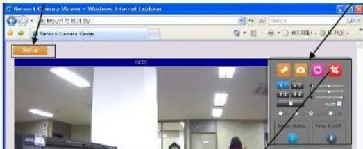
Network Camera Viewer - Windows Internet Explorer Set Up OES1) Connection through Speco-NVR
Click the camera assignment button for setting camera address. Input the description, address, Ch#, User ID, Password and port and then click the save button. After assignment procedure, you must click the SAVE button. You can see the live video when you click the live view button as below. When you exit Speco-NVR, you have to input the ID/PW, admin/1234. Details for the Speco-NVR can be found in [Speco-NVR User's Guide].

text_image
Camera Assignment Live view Exit Program ID Password Exit Program Default ID/PW: admin/12344. Initial Configuration by connecting Admin Mode
All Parameters of ONSIP OPTZ36XO/I are initially set as factory default. So you must change them with appropriate value to your network configuration by accessing via Admin Tool. Admin Tool Access Method is as below.
Http://[IP Address]:[HTTP Port No.]/ admin.htm
Admin Tool Access ID / Password: root / admin. As it is Default Value, please change them. For the detailed Configuration, please refer to [Configuration_Guide].
5. Trouble Shooting
5.1. No Video on Viewer
→ Network Connection Status Check(Ping Test)
You can check the Network Connection Status by doing Ping Test.
- Start > Run > cmd > Ping IP Address (EX>ping 172.16.42.51).
- If you get the response such as "Reply from\~", Network Configuration & Connection Status is good.
Please re-try to access or refer to other trouble shooting category. (1)
- If you get the response such as "Request timed out", Network Configuration & Connection Status is in problem. Please check the Network Cable and Configuration. (②)

text_image
C:\WINDOWS\Wsystem32\cmd.exe Microsoft Windows XP [Version 5.1.2600] (C) Copyright 1985-2081 Microsoft Corp. C:\Documents and Settings\Superman>ping 172.16.42.51 Pinging 172.16.42.51 with 32 bytes of data: Reply from 172.16.42.51: bytes=32 time(1ms TTL=64 C:\Documents and Settings\Superman>ping 172.16.42.51 Pinging 172.16.42.51 with 32 bytes of data: Request timed out.5.2. Windows vista and Windows 7 User for Record & Capture Problem
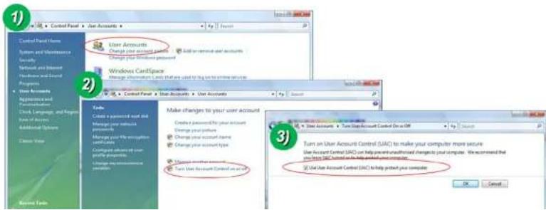
For the use of Video Recording & Capture function on Speco-NVR and Web Viewer, Windows Vista and Windows 7 Users are required to configure "User Account Configuration" and "Program Execution Entitlement Configuration". If not configure, Recorded File won't be generated or Captured Image on Web Viewer won't be saved.
Windows Vista Configuration
1. User Account Configuration
1) Select "User Account" on Control Panel
2) Select "Turn User Account Control on or off"
3) Uncheck "Use User Account Control to help protect your computer".
text_image
Control Panel Items System and Maintenance Security Network and Support Hardware and Services Programs User Accounts Application and Settings Clock, Language, and Settings Form of Accounts Additional Systems Show Data User Accounts Change your account point Change your Windows password Windows Certificate Change information set that are used for help to access services Control Panel User Accounts User Accounts Tools Create a password key and Manage your network Manage your file encryption Manage your user profile programs Manage your security settings Make changes to your user account Create a password for your account Change your status Change your account name Change your account type Manage your account name Turn User Account Control as an active Turn an User Account Control (UAC) to make your computer more secure User Account Control (UAC) can help prevent unaddressed changes to your computer. We recommend that you have UAC based on help protect your computer. Use User Account Control (UAC) to help protect your computer.ONSIP OPTZ O/I Users' Guide
text_image
Open Troubleshoot compatibility Open file location Run as administrator Pin to Taskbar Pin to Start Menu Restore previous versions Send to Cut Copy Create shortcut Delete Rename Properties
text_image
NVR Properties Security Details Previous Versions General Shortcut Compatibility If you have problems with this program and it worked correctly on an earlier version of Windows, select the compatibility mode that matches that earlier version. Help me choose the settings Compatibility mode Run this program in compatibility mode for: Windows XP (Service Pack 3) Settings Run in 256 colors Run in 640 x 480 screen resolution Disable visual themes Disable desktop composition Disable display scaling on high DPI settings Privilege Level Run this program as an administrator Change settings for all users OK Cancel ApplyWindows 7 Configuration
1. User Account Configuration
1) Select "User Account" on Control Panel
2) Select "Change User Account Control Setting"
3) Set the Alarm Level at the lowest "Never Notify"

ONSIP OPTZ O/I Users' Guide
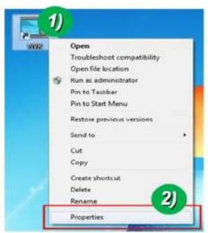
2. Program Execution Entitlement Configuration
1) Select "NVR" icon on the wallpaper
2) Select "Properties" menu popped up by clicking right button on Mouse
3) Select Check Box of "Run this program as an administrator" from the compatibility Tap.
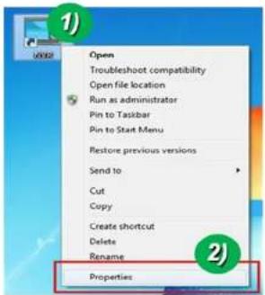
text_image
Open Troubleshoot compatibility Open file location Run as administrator Pin to Taskbar Pin to Start Menu Restore previous versions Send to Cut Copy Create shortcut Delete Rename Properties
text_image
MVE Properties Security Details Previous Versions General Shortcut Compatibility If you have problems with this program and it worked correctly on an earlier version of Windows, select the compatibility mode that matches that earlier version. Help me choose the settings Compatibility mode: □ Run this program in compatibility mode for: Windows XP (Service Pack 3) Settings □ Run in 256 colors □ Run in 640 x 480 screen resolution □ Disable visual themes □ Disable desktop composition □ Disable display scaling on high DPI settings Privilege Level ✓ Run this program as an administrator Change settings for all users OK Cancel Apply5.3 Technical Inquiry
Please contact to your supplier if you still have problem even taking all trouble shootings.
For the quickest solution, please prepare all information below;
- Product Model Name
- Serial No. & Mac Address
- Date of Purchase
- Summary of Problem
- Error Message

6. Appendix
6.1. FAN & Heater
FAN & Heater is inside Housing of Outdoor Speed Dome.
At ONSIP OPTZ36XO/I, FAN & Heater will operate.
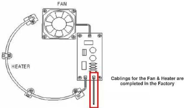
text_image
FAN HEATER Cabling for the Fan & Heater are completed in the FactoryAt ONSIP OPTZ36XO/I, FAN & Heater will operate by connecting power cable of FAN & Heater to
ONSIP OPTZ O/I Users' Guide
| Weight | 3.4kg (including Camera : 5.3kg) |
6.2. DIP Switch Setting
A. ID Configuration
* Factory Default: Camera ID = 1

(1-ON, 0-OFF)
| DIP SW | ID VALUE | DIP SW | ID VALUE | DIP SW | ID VALUE |
| 10000000 | 1 | 00010100 | 40 | 11110010 | 79 |
| 01000000 | 2 | 10010100 | 41 | 00001010 | 80 |
| 11000000 | 3 | 01010100 | 42 | 10001010 | 81 |
| 00100000 | 4 | 11010100 | 43 | 01001010 | 82 |
| 10100000 | 5 | 00110100 | 44 | 11001010 | 83 |
| 01100000 | 6 | 10110100 | 45 | 00101010 | 84 |
| 11100000 | 7 | 01110100 | 46 | 10101010 | 85 |
| 00010000 | 8 | 11110100 | 47 | 01101010 | 86 |
| 01101000 | 22 | 10111100 | 61 | 00100110 | 100 |
| 11101000 | 23 | 01111100 | 62 | 10100110 | 101 |
| 00011000 | 24 | 11111100 | 63 | 01100110 | 102 |
| 10011000 | 25 | 00000010 | 64 | 11100110 | 103 |
| 01011000 | 26 | 10000010 | 65 | 00010110 | 104 |
| 11011000 | 27 | 01000010 | 66 | 10010110 | 105 |
| 00111000 | 28 | 11000010 | 67 | 01010110 | 106 |
| 10111000 | 29 | 00100010 | 68 | 11010110 | 107 |
| 01111000 | 30 | 10100010 | 69 | 00110110 | 108 |
| 11111000 | 31 | 01100010 | 70 | 10110110 | 109 |
| 00000100 | 32 | 11100010 | 71 | 01110110 | 110 |
| 10000100 | 33 | 00010010 | 72 | 11110110 | 111 |
| 01000100 | 34 | 10010010 | 73 | 00001110 | 112 |
| 11000100 | 35 | 01010010 | 74 | 10001110 | 113 |
| 00100100 | 36 | 11010010 | 75 | 01001110 | 114 |
| 10100100 | 37 | 00110010 | 76 | 11001110 | 115 |
| 01100100 | 38 | 10110010 | 77 | 00101110 | 116 |
| 11100100 | 39 | 01110010 | 78 | 10101110 | 117 |
| 01101110 | 118 | 00100101 | 164 | 01001011 | 210 |
| 11101110 | 119 | 10100101 | 165 | 11001011 | 211 |
| 00011110 | 120 | 01100101 | 166 | 00101011 | 212 |
| 10011110 | 121 | 11100101 | 167 | 10101011 | 213 |
| 11100001 | 135 | 10101101 | 181 | 11000111 | 227 |
| 00010001 | 136 | 01101101 | 182 | 00100111 | 228 |
| 10010001 | 137 | 11101101 | 183 | 10100111 | 229 |
| 01010001 | 138 | 00011101 | 184 | 01100111 | 230 |
| 11010001 | 139 | 10011101 | 185 | 11100111 | 231 |
| 00110001 | 140 | 01011101 | 186 | 00010111 | 232 |
| 10110001 | 141 | 11011101 | 187 | 10010111 | 233 |
| 01110001 | 142 | 00111101 | 188 | 01010111 | 234 |
| 11110001 | 143 | 10111101 | 189 | 11010111 | 235 |
| 00001001 | 144 | 01111101 | 190 | 00110111 | 236 |
| 10001001 | 145 | 11111101 | 191 | 10110111 | 237 |
| 01001001 | 146 | 00000011 | 192 | 01110111 | 238 |
| 11001001 | 147 | 10000011 | 193 | 11110111 | 239 |
| 00101001 | 148 | 01000011 | 194 | 00001111 | 240 |
| 10101001 | 149 | 11000011 | 195 | 10001111 | 241 |
| 01101001 | 150 | 00100011 | 196 | 01001111 | 242 |
| 11101001 | 151 | 10100011 | 197 | 11001111 | 243 |
| 00011001 | 152 | 01100011 | 198 | 00101111 | 244 |
| 10011001 | 153 | 11100011 | 199 | 10101111 | 245 |
| 01011001 | 154 | 00010011 | 200 | 01101111 | 246 |
| 11011001 | 155 | 10010011 | 201 | 11101111 | 247 |
| 00111001 | 156 | 01010011 | 202 | 00011111 | 248 |
B. PROTOCOL
Set by 3^rd , 4^th Switch of DIP Switch 2.
Factory Default: Pelco-D & Pelco-P (Auto)
| DIP SW2 - 3 ^rd 4 ^th | |
| OFF / OFF | Pelco-D or Pelco-P |
| ON / ON | Maxpro protocol |
C. BAUD RATE SETTING
Set by 7^th , 8^th Switch of DIP Switch 2.
Changeable Speed: 4800bps, 9600bps
Factory Default: 2400bps.
| DIP SW2-7th | DIP SW2-8th | BAUD RATE |
| OFF | OFF | Not Used |
| OFF | ON | 2400bps |
| ON | OFF | 4800bps |
| ON | ON | 9600bps |
* 5 ^th , 6 ^th Switch of DIP Switch 2 is not used.