DVR82HD - Security Camera Speco Technologies - Free user manual and instructions
Find the device manual for free DVR82HD Speco Technologies in PDF.

| Product Type | 8-Channel HD DVR |
| Brand | Speco Technologies |
| Model | DVR82HD |
| Video Input | 8 BNC channels |
| Recording Resolution | Up to 1080p (HD) |
| Compression | H.265+/H.265/H.264 |
| Display Resolution | 1920x1080p |
| Hard Drive Capacity | Up to 10TB (1 SATA bay) |
| Audio | 1 channel input, 1 channel output (RCA) |
| Network | 10/100 Mbps Ethernet, RJ-45 |
| Remote Viewing | Via web browser or mobile app (iOS/Android) |
| Power Supply | 12V DC, 2A adapter |
| Power Consumption | ≤ 10W (without HDD) |
| Dimensions (WxHxD) | 12.2 x 1.7 x 10.2 inches (310 x 43 x 260 mm) |
| Weight | 4.4 lbs (2.0 kg) |
| Operating Temperature | 14°F to 122°F (-10°C to 50°C) |
| Certification | FCC, CE, RoHS |
| Main Features | Motion detection, scheduled recording, playback, backup via USB, remote access |
| Cleaning | Wipe exterior with dry soft cloth; disconnect power before cleaning |
| Safety | Use only supplied power adapter; avoid moisture; ensure proper ventilation |
| Spare Parts / Repairability | Replaceable hard drive; power adapter available from Speco |
Frequently Asked Questions - DVR82HD Speco Technologies
User questions about DVR82HD Speco Technologies
0 question about this device. Answer the ones you know or ask your own.
Ask a new question about this device
Download the instructions for your Security Camera in PDF format for free! Find your manual DVR82HD - Speco Technologies and take your electronic device back in hand. On this page are published all the documents necessary for the use of your device. DVR82HD by Speco Technologies.
USER MANUAL DVR82HD Speco Technologies
Explanation of Graphical Symbols

This symbol indicates the presence of important operang and maintenance (servicing) instrucons in the literature accompanying the product.

This symbol indicates the presence of "dangerous voltage" within the product's enclosure that may be of sucient magnitude to constute a risk of electric shock, property damage, personal injury, or death.
These precautions must be followed for safety reasons.

Warning
- Do not use if the unit emits smoke.
- Do not disassemble the unit.
- Do not place any heavy or sharp objects on the unit.
- Do not place on uneven surface.
- Do not expose to shock or vibration.
- Do not move the unit when the unit is powered on.
- Do not block, and allow dust to accumulate in the air vents.
- Do not restrict airflow of the unit; doing so can damage the unit.
- Installation and servicing should be performed only by qualified and experienced personnel.
- Turn off the power of the DVR when connecting Cameras, Audio or Sensor Cables.
- The manufacture is not responsible for any damage caused by improper use of the product or failure to follow instructions for the product.
- The manufacture is not responsible for any problems caused by or resulting from the user physically opening the DVR for examination or attempting to repair the unit.
Product Components
Please make sure the following components are included as specified below.
| DVR Unit |  | ||
| Client Software CD |  | ||
| Remote Control |  | ||
| Battery1.5V (AAA x 2EA) | [GAW0] | ||
| User's Guide |  | ||
| HDD SATA Cable (4 EA) |  | ||
| HDD Mounting Brackets (2 EA) | 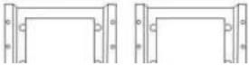 | ||
Hard Drive Installation
- Remove the screws and the top cover as specified below.
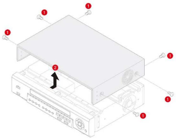
text_image
Diagram of an internal computer drive with numbered components and a black arrow indicating a component or assembly.-
Fix the supplied HDD mounting bracket to the hard disk using the supplied mounting bracket screws.
-
Insert the HDD bracket to the hole and fix the screw.
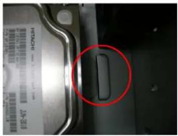
natural_image
Close-up of a mechanical component with a red circle highlighting a specific part (no visible text or symbols)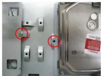
natural_image
Close-up of a metallic mechanical component with two red-circled holes, no visible text or symbols- Connect the supplied SATA cable and power cable to the hard disk.
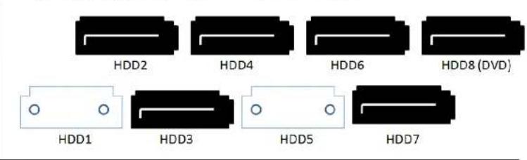
NOTE) HDD2 SATA port is the main HDD port. When installing more than 2 HDDs, connect HDD SATA cables in sequential order from HDD2.
Storage Estimation
Recording Condition
- Channel and Frame: 10 Channels (Full-HD@15fps or HD@30fps and D1@30/25fps)
- Recording by: Continuous
- Audio Recording: 10 Channel Audio On
| HDD | LEVEL 5(H) | LEVEL 4 | LEVEL 3 | LEVEL 2 | LEVEL 1(L) | |||||
| day(s) | hour(s) | day(s) | hour(s) | day(s) | hour(s) | day(s) | hour(s) | day(s) | hour(s) | |
| 250GB | 0 | 15 | 0 | 19 | 1 | 2 | 1 | 7 | 1 | 14 |
| 320GB | 0 | 20 | 1 | 1 | 1 | 10 | 1 | 16 | 2 | 2 |
| 500GB | 1 | 9 | 1 | 17 | 2 | 6 | 2 | 17 | 3 | 8 |
| 1TB | 2 | 19 | 3 | 12 | 4 | 15 | 5 | 12 | 6 | 20 |
| 1.5TB | 4 | 6 | 5 | 7 | 7 | 0 | 8 | 8 | 10 | 8 |
| 2TB | 5 | 16 | 7 | 2 | 9 | 9 | 11 | 4 | 13 | 20 |
Specifications
| Model | DVR82HD | ||
| Video | Input | Channel Input Level | 2 CH HDcctv 720p / 1080p8 CH Composite |
| Video Loss Check | YES | ||
| Output | Main Monitor Output | 1 HDMI (Max. 1920x1080p60 and Various Resolution) | |
| Sub Monitor Output | 1 VGA (Max. 1920x1080p60 and Various Resolution) | ||
| CVBS and Spot | 1 CVBS , 4 SPOT OUT | ||
| Audio | Input and Output | 10 CH Input & 1 CH Output | |
| Audio Codec | G.711 | ||
| Alarm | Sensor Input | 10 TTL, NC/NO Selectable | |
| Alarm Out | 4 Relay Out by Sensor, Motion and Video Loss | ||
| Record | Compression | H.264 (Main Profile) | |
| Multi Operation | Quadplex (Playback, Recording, Backup, Network) | ||
| Resolution | HDcctv: 1920*1080, 1920*540, 1280*720, 640*360Composite: 704x480, 704x240, 352x240 | ||
| Recording Quality Grade | 4 Levels | ||
| Recording Mode | Continuous, Schedule, Motion, Sensor, Manual | ||
| Motion Detection | Setup by Grid | ||
| Pre Recording | 15 Seconds to 20 Minutes | ||
| Post Recording | 10 Seconds to 60 Seconds | ||
| Playback | Multi Decoding | 1, 4, 8, 10 | |
| Playback Speed | Single Channel FF/FR | x0.25, x0.5, x2, x4, x8, x16, x32 | |
| Multi Channel FF/FR | x0.25, x0.5, x2, x4, x8, x16, x32 | ||
| Network Interface | 10/100/1000 Base TX Ethernet (RJ45 1EA) | |
| Dual Network Streaming | 2 CH HDcctv: H.264 640*360@120fps / 1280*720@120fps8 CH Composite: CIF@240fps / D1@240fps | |
| Network Access | Web viewer (1:1) | Live, Search, Backup, PTZF |
| 3G Mobile Viewer (1:1) | Live | |
| Multi sites Monitoring Software(1:N) | Live, Search, Backup, PTZF | |
| Features | DLS (Day Light Saving) | YES |
| Internal Beep | By Alarm, Motion, Video Loss, HDD Error | |
| Multi Language | Yes | |
| Software Upgrade | By USB Flash Drive, Network Remote Upgrade | |
| NTP (Network Time Protocol) | YES | |
| Digital Zoom | YES | |
| Remote Setup | YES | |
| General | Operation Condition | 0~40C, Humidity 20~80% |
| Power | AC 100~127V/200~240V, 5~60Hz, 280W | |
| Net Weight (Gross Weight) | 6KGS (9.5KGS) / 13.2LBS (20.9LBS) | |
| Unit Dimension (W x D x H) | 417mm x 432mm x 99mm / 16.4" x 17" x 3.9" |
Please note that specifications and unit exterior design are subject to change without notification.
Table of Contents
- Main Features 13
- Booting the System and Initial Setting 14
2-1. Booting the DVR and Basic Time Setting....14
2-2. Setting Daylight Saving Time....15
2-3. Setting NTP (Network Time Protocol) 16 - Name, Function and Connection 19
3-1. Front Panel....19
3-2. Rear Panel 20
3-3. Remote Control 21 - Setting up the DVR....22
4-1. Setup – Main Live Screen....22
4-2. Setup - DISPLAY 23
4-3. Setup - RECORD 25
4-3-1. Recording Schedules 27
4-4. Setup - DEVICE....28
4-4-1. ALARM-OUT 29
4-4-2. Controller & PTZ Setup 30
4-4-3. Spot Out....31
4-4-4. Motion Zone Setup 32
4-5. Setup - STORAGE....33
4-6. Setup - SYSTEM 35
4-7. Setup – SECURITY 38
4-8. Setup - NETWORK....40
4-8-1. Network Types .... 41
5-3-6. Archive Search....52
5-3-7. Log Search....52
5-4. Play Mode 53
6. PTZ Control 54
7. Back Up....55
7-1. Still Image Backup onto USB Flash Drive 55
7-2. Video Backup onto USB Flash Drive ....55
7-3. Transferring Still Images or Video from the ARCHIVE List 56
7-4. Playback of Backup Video....57
8. Network Access Using of SpecoTech Multi Client 59
8-1. Overview 59
8-2. PC Requirements 59
8-3. Installation of the Program....60
8-4. Live Window....61
8-4-1.Main User Interface 61
8-4-2. Control Buttons 61
8-5. Search and Playback Window 63
8-5-1.Main User Interface 63
8-5-2. Main Control Panel....63
8-6. Setup of SpecoTech Multi Client 66
8-6-1. General 66
8-6-2. Event......67
8-6-3. Record 68
8-6-4. Display 69
8-6-5. About....69
8-7. Remote Setup 70
10-1. 3G App Viewer for iPhone 89
10-2. 3G App Viewer for Android Phone 91
APPENDIX: Network Connection - LAN 93
APPENDIX: Network Connection – Internet and DDNS 95
APPENDIX: E-SATA CONNECTION 99
1. Main Features
■ HDcctv Compatible
■ 2 channel HDcctv and 8 channel analog full D1
■ Easy Record, Copy and Setup
■ Recording Rate: 120fps @ 720p HDcctv resolution
■ H.264 high quality compression saves HDD space
■ Simultaneous live view/playback while continuing to record/network transfer or backup
■ Remote monitoring/recording/playback/configuration and control via internet
■ 4 Channel Audio Recording
NOTE: Under federal law, The Fourth Amendment to the U.S. Constitution, Title III of the Omnibus Crime Control and Safe Streets Act of 1968, as amended by the Electronic Communications Privacy Act of 1986 (18 U.S.C. § 2510, et seq.), and the Foreign Intelligence Surveillance Act of 1978 (50 U.S.C. 1801, et seq.) permit government agents, acting with the consent of a party to a communication, to engage in warrantless interceptions of telephone communications, as well as oral and electronic communications.
■ Automatic camera detection (Plug & Play)
■ Covert camera operation provides enhanced security and administrator control
■ Dynamically programmable recording priority, motion detection, alarms and scheduling
■ Simple and Easy Graphic User Interface
■ Simple Scheduler
■ Simple Schedule
■ HDMI Output / VGA Output
2. Booting the System and Initial Setting
2-1. Booting the DVR and Basic Time Setting
- During the first start up, the following logo and message will be displayed.

text_image
speco technologies®
text_image
Initializing system It may take a few seconds of minutes to check system 0% Initializing...- After the system initializing is completed, select the language and set date and time as specified below.
2-2. Setting Daylight Saving Time
To enable Daylight Saving feature/NTP synchronization, take the following steps.
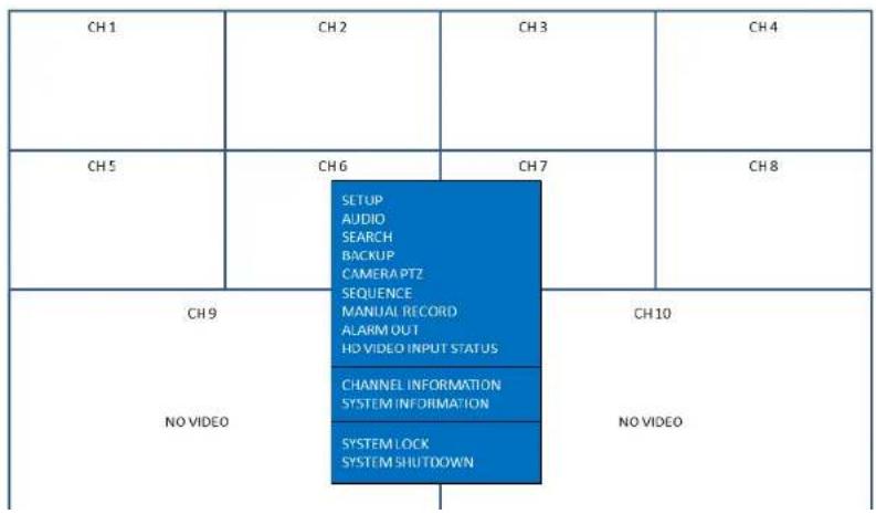
- Enter the SETUP mode. The default Password is "1111".
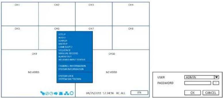
text_image
CH1 CH2 CH3 CH4 CH5 CH6 CH7 CH8 CH9 NO VIDEO SETUP ADDRESS SEARCH BACKUP COME RAPTY SEQUENCE MANUAL RECORD ALARM CUT NO VIDEO INPUT STATUS CHANNEL INFORMATION SYSTEM INFORMATION SYSTEM LOCK SYSTEM SHUTDOWN NO VIDEO 04/25/2011 1:2:34:56 RC ALL 0% USER ADMIN PASSWORD OK CANCEL- Go to SETUP>SYSTEM>SET DATE & TIME
text_image
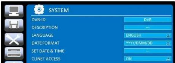
SYSTEM DVR-ID DVR DESCRIPTION -- LANGUAGE ENGLISH DATE FORMAT YYYY/DMM/DD SET DATE & TIME -- CLINET ACCESS ON2-3. Setting NTP (Network Time Protocol)
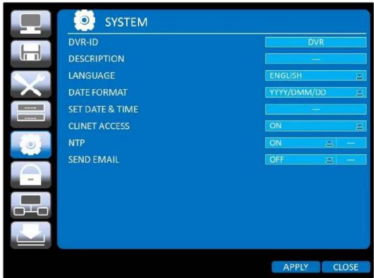
- When the DVR is connected with internet and the DVR need to be synchronized with NTP (Network Time Protocol), set SETUP>SYSTEM>NTP ON.
text_image
SYSTEM DVR-ID DESCRIPTION LANGUAGE DATE FORMAT SET DATE & TIME CLINET ACCESS NTP SEND EMAIL DVR ENGLISH YYYY/DMM/DD ON ON OFF APPLY CLOSE- Select proper TIME ZONE time.
| AR | Arkansas | GMT-6 | GMT-5 |
| CA | California | GMT-8 | GMT-7 |
| CO | Colorado | GMT-7 | GMT-6 |
| CT | Connecticut | GMT-5 | GMT-4 |
| DC | District of Columbia | GMT-5 | GMT-4 |
| DE | Delaware | GMT-5 | GMT-4 |
| FL | Florida | GMT-5 | GMT-4 |
| FL | Florida (W) | GMT-6 | GMT-5 |
| GA | Georgia | GMT-5 | GMT-4 |
| HI | Hawaii | GMT-10 | NA |
| ID | Idaho (N) | GMT-8 | GMT-7 |
| ID | Idaho (S) | GMT-7 | GMT-6 |
| IL | Illinois | GMT-6 | GMT-5 |
| IN | Indiana | GMT-5 | GMT-4 |
| IN | Indiana (SW / NW) | GMT-6 | GMT-5 |
| IA | Iowa | GMT-6 | GMT-5 |
| KS | Kansas | GMT-6 | GMT-5 |
| KS | Kansas (W) | GMT-7 | GMT-6 |
| KY | Kentucky (E) | GMT-5 | GMT-4 |
| KY | Kentucky (W) | GMT-6 | GMT-5 |
| LA | Louisiana | GMT-6 | GMT-5 |
| ME | Maine | GMT-5 | GMT-4 |
| MD | Maryland | GMT-5 | GMT-4 |
| MA | Massachusetts | GMT-5 | GMT-4 |
| MI | Michigan | GMT-5 | GMT-4 |
| OH | Ohio | GMT-5 | GMT-4 |
| OK | Oklahoma | GMT-6 | GMT-5 |
| OR | Oregon | GMT-8 | GMT-7 |
| OR | Oregon (E) | GMT-7 | GMT-6 |
| PA | Pennsylvania | GMT-5 | GMT-4 |
| RI | Rhode Island | GMT-5 | GMT-4 |
| SC | South Carolina | GMT-5 | GMT-4 |
| SD | South Dakota (E) | GMT-6 | GMT-5 |
| SD | South Dakota (W) | GMT-7 | GMT-6 |
| TN | Tennessee (E) | GMT-5 | GMT-4 |
| TN | Tennessee (W) | GMT-6 | GMT-5 |
| TX | Texas | GMT-6 | GMT-5 |
| TX | Texas (W) | GMT-7 | GMT-6 |
| UT | Utah | GMT-7 | GMT-6 |
| VT | Vermont | GMT-5 | GMT-4 |
| VA | Virginia | GMT-5 | GMT-4 |
| WA | Washington | GMT-8 | GMT-7 |
| WV | West Virginia | GMT-5 | GMT-4 |
| WI | Wisconsin | GMT-6 | GMT-5 |
| WY | Wyoming | GMT-7 | GMT-6 |

NOTE: If you want the unit to automatically synchronize the local time, the Time Zone must be properly set according to your local time zone.
3. Name, Function and Connection
3-1. Front Panel
The following information will help you to operate the front panel controls.
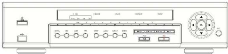
Figure 3.1.1. Front Panel
Table 3.1.1. Indication Lamps
| Name | Description |
| CH1~10 | Indicating that the channel is being recorded. |
| HDD | Indicating that the system is accessing the hard disk. |
| RECORD | Indicating that the system is recording video data. |
| ALARM | Indicating that when sensor(s) is/are triggered or motion is detected. |
| NETWORK | Indicating that when Network client connects through the network. |
| BACKUP | Indicating that USB or DVD-RW storage device is stored images or video. |
Table 3.1.2. Front Panel Buttons
| Name | Description |
| POWER | POWER ON/OFF |
| NUMBER | Channel keys. For channel 10, press the 0 key. For channel 11, press the +10 and 1 |
| SEARCH | Press to go to SEARCH menu in live display mode. |
| [0000] | Press to move left or to change the values in Setup mode.It is also used as the number 4 when entering password. |
 | Press to move up the menu in Setup mode.It is also used as the number 1 when entering password. |
| [778] | Press to move right or to change the values in Setup mode.It is also used as the number 2 when entering password. |
 | Press to move down the menu in Setup mode.It is also used as the number 3 when entering password. |
| [TW75] | Press to select desired menu item or to store the setup value. |
| ESC | Press for temporary storage of the changed value or to return to the previous menu screen. |
| USB Port | To archive still-image or video into a USB memory or upgrade firmware with USB memory stick, connect a USB memory to the USB terminal on the front panel. |
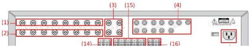
3-2. Rear Panel
text_image
(1) (2) (3) (15) (4) (14) (16)| 6 | VGA | Connector for VGA monitor. |
| 7 | HDMI OUT | Main Video Output |
| 8 | USB Port | Connector for Mouse or Backup |
| 9 | RS-232 | POS Interface (TBD). |
| 10 | ETHERNET | RJ-45 connector for network function |
| 11 | E-SATA | 2 e-SATA ports to archive still-image or video into a External Storage HDD . RAID Units to be available in the future |
| 12 | TERMINATE | RS-485 termination switch for 1^st and 2^nd . |
| 13 | POWER SOCKET | Connect for AC110V~250V |
| 14 | RS-485 | 1^st and 2^nd ports for RS-485. |
| 15 | SENSOR IN | 10 connectors for sensor device connection. |
| 16 | ALARM OUT | 4 connectors for alarm device connection. Provides simple On/Off switching by using relay. 0.5A/125V, 1A/30V |
3-3. Remote Control
 | RECORD | Manual recording |
| DISPLAY | Display of Full, Quad,9 or 16 split screen | |
| F/REW | Jump 60 seconds backward | |
| PLAY/PAUSE | Play/Pause | |
| F/ADV | Jump 60 seconds forward | |
| REW | Rewind | |
| BACKUP | Backup still or video data | |
| FF | Fast Forward | |
| ALARM | Disable alarm operation |
4. Setting up the DVR
The following sections detail the initial setup of the DVR.

Menu screen will close if user input is not received in 5 minutes.
4-1. Setup – Main Live Screen
To enter the setup menu, click on the mouse right button and select setup from the submenu or press the setup button on the front panel or the remote control.
flowchart
graph TD
    A["CH 1"] --> B["SETUP"]
    A --> C["AUDIO"]
    A --> D["SEARCH"]
    A --> E["BACKUP"]
    A --> F["CAMERA PTZ"]
    A --> G["SEQUENCE"]
    A --> H["MANUAL RECORD"]
    A --> I["ALARM OUT"]
    A --> J["NO VIDEO INPUT STATUS"]
    K["CH 9"] --> L["CHANNEL INFORMATION"]
    K --> M["SYSTEM INFORMATION"]
    K --> N["SYSTEM LOCK"]
    K --> O["SYSTEM SHUTDOWN"]
    P["NO VIDEO"] --> Q["CH 10"]
    R["CH 5"] --> S["CH6"]
    T["CH 7"] --> U["CH 8"]
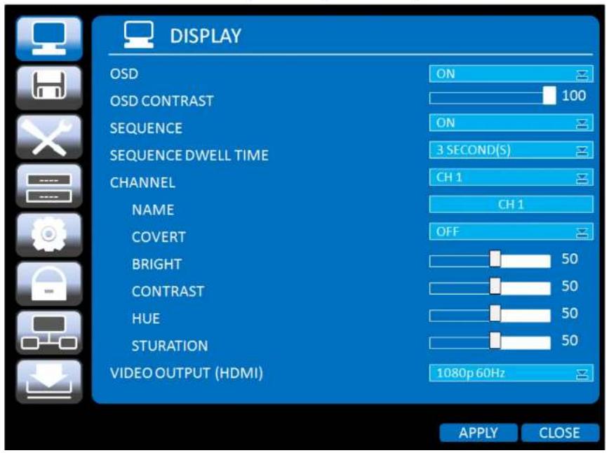
4-2. Setup - DISPLAY
In the SETUP menu, select the DISPLAY tab. Then, the DISPLAY menu is displayed as pictured below. Navigate through the menu items using the mouse or the control button on the remote control and change the value of the menu item. To return to the previous setup menu screen, press the ESC button.
text_image
DISPLAY OSD ON OSD CONTRAST 100 SEQUENCE ON SEQUENCE DWELL TIME 3 SECOND(S) CHANNEL CH 1 NAME CH 1 COVERT OFF BRIGHT 50 CONTRAST 50 HUE 50 STURATION 50 VIDEO OUTPUT (HDMI) 1080p 60Hz APPLY CLOSE| COVERT | Enable/disable display of the video channel in live display mode. |
| BRIGHTNESS | Change the brightness value of the specified channel.(0-100)It is for analog channels (1~8ch) only and is not for HDcctv channels (9,10ch). |
| CONTRAST | Change the contrast value of the specified channel. (0-100)It is for analog channels (1~8ch) only and is not for HDcctv channels (9,10ch). |
| HUE | Change the hue value of the specified channel. (0-100)It is for analog channels (1~8ch) only and is not for HDcctv channels (9,10ch). |
| SATURATION | Change the saturation value of the specified channel. (0-100)It is for analog channels (1~8ch) only and is not for HDcctv channels (9,10ch). |
| VIDEO OUTPUT(HDMI/VGA) | Select a video output type for HDMI- 720p 50Hz- 720p 60Hz- 1080i 50Hz- 1080i 60Hz- 1080p 50Hz- 1080p 60HzDefault value is 720p 60Hz. If the monitor doesn't support some output type, it would be returned to the previous value. |
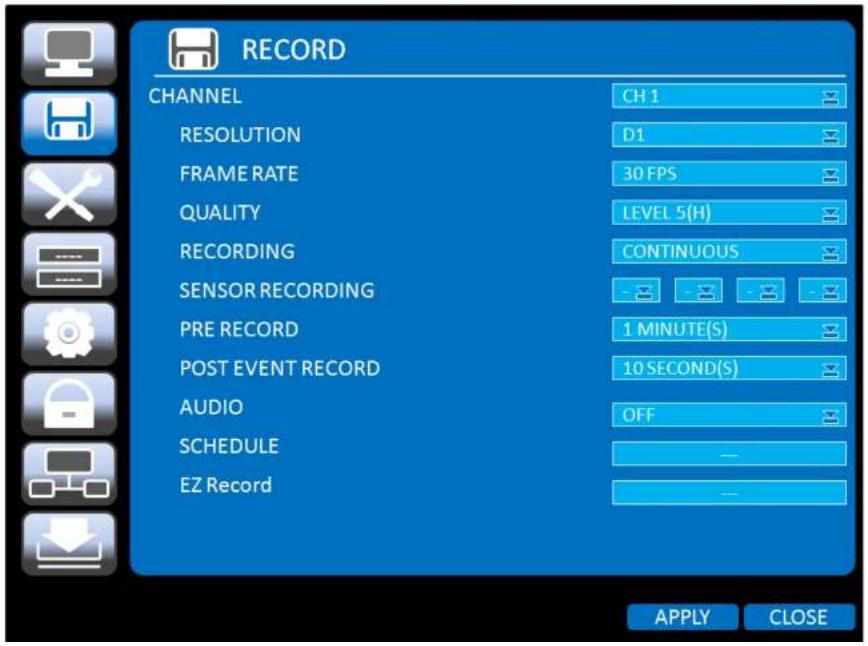
4-3. Setup - RECORD
In the SETUP menu, select the RECORD tab. Then, the RECORD menu is displayed as pictured below. Navigate through the menu items using the mouse or the control button on the remote control and change the value of the menu item.
text_image
RECORD CHANNEL CH 1 RESOLUTION D1 FRAME RATE 30 FPS QUALITY LEVEL 5(H) RECORDING CONTINUOUS SENSOR RECORDING - - - - - PRE RECORD 1 MINUTE(S) POST EVENT RECORD 10 SECOND(S) AUDIO OFF SCHEDULE - EZ Record - APPLY CLOSE| QUALITY | Select the recording quality for the specified channel. Options are:Level 1 (Low), Level 2, Level 3, Level 4, and Level 5 (High) |
| RECORDING | Assign the recording mode for each channel. Options are: Continuous, Motion, Sensor, Schedule or Disable. |
| SENSOR RECORDING | Enable setting up to 4 sensors for the specified channel using the mouse or th control button of the remote control. |
| PRE RECORD | Enable/disable pre-event recording. Pre-event recording time is 15 seconds to 20 minutes (Selectable) |
| POST EVENT RECORD | Set the post event recording time duration for the specified channel.(10~60 seconds) |
| AUDIO | Enable/disable audio recording for the specified channel. |
| SCHEDULE | Set the recording schedule. |
| EZRECORD | Set the recording by EZRecord feature.The EZRECORD has high priority than other setting values on RECORD.User can change the setting value such as resolution, frame rate, quality and recording type. By the setting value, the DAYS TO RECORD will change accordingly. |
| RESOLUTION | D1 | 1280 x 720 |
| FRAME RATE | 30 FPS | 30 FPS |
| QUALITY | LEVEL 5(H) | LEVEL 5(H) |
| RECORDING | CONTINUOUS | |
| DAYS TO RECORD | 3 DAYS(S) 23 HOUR(S) | |
| APPLY | CLOSE | |
4-3-1. Recording Schedules
To setup a recording schedule, select SCHEDULE in the RECORD menu. Navigate through the items using the mouse or the control button.
Select CHANNEL > select NONE, CONTINUOUS or MOTION > HIGHLIGHT AREA
To copy a schedule to a different channel, select the channel from the COPY SCHEDULE menu.

text_image
CHANNEL 1 NONE CONTINUE MOTION SENSOR CLEAR 0 1 2 3 4 5 6 7 8 9 10 11 12 13 14 15 16 17 18 19 20 21 22 23 SUN MON TUE WED THU FRI SAT COPY SCHEDULE CH 1 CH 2 CH 3 CH 4 ALL CH 5 CH 6 CH 7 CH 8 CH 9 CH 10 CH 11 CH 12 CH 13 CH 14 CH 15 CH 16 COPY OK CANCELFigure 4.3.2. Schedule recording setup screen
NONE: Disable recording
CONTINUE: CONTINUOUS recording (Highlahted in Green)
4-4. Setup - DEVICE
In the SETUP menu, select the DEVICE tab. Then, the device menu is displayed as pictured below. Navigate through the menu items using the mouse or the control button on the remote control and change the value of the menu item.

text_image
DEVICE ALARM-OUT CONTROLLER & PTZ SPOT-OUT CHANNEL CH 1 MOTION ZONE FULL ZONE MOTION SENSITIVITY 9 KEY TONE OFF REMOTE CONTROLLER ID 0 SENSOR 1 TYPE OFF APPLY CLOSE| 2. Press the same number as ID set in DVR on the remote control.3. An icon will be displayed on the Live Screen that corresponds to the remote control ID number.0The options are from 0 to 99 | |
| SENSOR | Select sensor from 1 to 10. |
| TYPE | Set the type of sensor for the specified channel. Options are:OFF, NORMAL OPEN, and NORMAL CLOSE. |
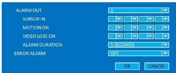
4-4-1. ALARM-OUT
text_image
ALARM OUT 1 SENSOR IN ... MOTION ON ... VIDEO LOSS ON ... ALARM DURATION 5 SECONDS ERROR ALARM OFF OK CANCELFigure 4.4.2. ALARM-OUT Setup Screen
Table 4.4.2. Menu Item in ALARM-OUT Setup Screen
| Item | Description |
| ALARM OUT | Select an Alarm out number. |
| SENSOR IN | Enable Alarm Out by Sensor from 1 to 10 Inputs. |
| MOTION ON | Enable Alarm Out by Camera Motion from 1 to 10 cameras. |
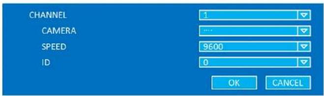
4-4-2. Controller & PTZ Setup
text_image
CHANNEL CAMERA SPEED ID 1 9600 0 OK CANCELFigure 4.4.3. Controller & PTZ Control Setup Screen
Table 4.4.3. Menu Item in Controller & PTZ Control Setup Screen
| Item | Description |
| CHANNEL | Select Channel number that the PTZ is connected to |
| CAMERA | Select the protocol type of the PTZ camera that is connected. |
| SPEED | Select the Baud Rate from 19200, 14400, 9600, 4800, 2400 |
| ID | Select the ID of the PTZ camera |
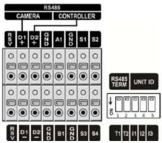
text_image
RS485 CAMERA CONTROLLER RSV D1 D2 GND A1 GND S1 S2 RSV D1 D2 GND B1 GND S3 S4 RS485 TERM UNIT ID T1 T2 T3 T4 T5 S1 S2 S3 S44-4-3. Spot Out

text_image
SPOT OUT SPOT TYPE SPOT ON EVENT SPOT EVENT DWELL TIME SEQUENCE SPOT CHANNEL SPOT 1 QUAD OFF 3 SECOND(S) OFF 1 2 3 4 5 6 7 8 9 10 OK CANCELFigure 4.4.4. SPOT-OUT Setup Screen
Table 4.4.4. Menu Item in SPOT-OUT Setup Screen
| Item | Description |
| SPOT OUT | Spot Out 1: from 1 channel to 4 channelSpot Out 2: from 5 channel to 8 channelSpot Out 3: for 9 channelSpot Out 4: for 10 channel |
| SPOT TYPE | Select Full screen or Quad screen mode. |
| SPOT ON EVENT | Enable/Disable display of the channel when an event is active |
4-4-4. Motion Zone Setup
Select MOTION ZONE using the mouse or the control button on the remote control and select either PARTIAL ZONE or FULL ZONE using the mouse control. The default value is FULL ZONE.
If FULL ZONE is selected, the motion zone grid screen is not displayed. Only set the level of sensitivity for MOTION SENSITIVITY.
FULL ZONE: The motion sensor is active on the whole screen.
PARTIAL ZONE: The motion sensor is active in the set detection frame.
Select the motion detection position using the mouse or the control button on the remote control. Then left click on the mouse or left click and drag the mouse pointer to select or deselect the area. Highlighted area indicates the partial motion detection zone. Press the ESC button or right click on the mouse to return to the previous menu.

natural_image
Interior view of a modern office or lab space with wooden flooring and glass partitions, no visible text or symbols.Figure 4.4.4. Motion Zone Grid Screen
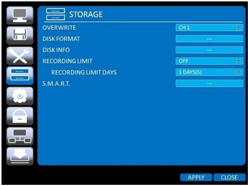
4-5. Setup - STORAGE
In the SETUP menu, select the STORAGE tab. Then, the STORAGE menu is displayed as pictured below. Navigate through the menu items using the mouse or the control button on the remote control and change the value of the menu item.
text_image
STORAGE OVERWRITE CH 1 DISK FORMAT --- DISK INFO --- RECORDING LIMIT OFF RECORDING LIMIT DAYS 1 DAYS(S) S.M.A.R.T. --- APPLY CLOSEWarning
Will you format HDD?
If yes, all the data will be erased from HDD.
If the data is to be kept, select NO.
YES
NO
DISK INFO
Hard drive information.
Displays the following information;
- HDD Size
- HDD Start Time and HDD Last Time
- Model name
- Temperature
- Power on time
- HDD Health status
RECORDING
Enable/disable recording limit.
LIMIT
RECORDING
Set the recording limit days. (1-90 days)
LIMIT DAYS
If the RECORDING LIMIT DAYS is set to 1, the data will be overwritten after 24 hours.
S.M.A.R.T
Set the alarm and beep by setting the HDD temperature limit.
TEMPERTURE LIMIT
ALARM
45 C (113 F)
ON
4-6. Setup - SYSTEM
In the SETUP menu, select the SYSTEM tab. Then, the SYSTEM menu is displayed as pictured below.
Navigate through the menu items using the mouse or the control button on the remote control and change the value of the menu item.

text_image
SYSTEM DVR-ID DESCRIPTION LANGUAGE DATE FORMAT SET DATE & TIME CLINET ACCESS NTP SEND EMAIL DVR ENGLISH YYYY/DMM/DD ON ON OFF APPLY CLOSE
text_image
SOFTWARE VERSION VER. 1.2.3 (20110425) STORAGE SIZE 921 GB IP ADDRESS 192.168.1.80 MAC ADDRESS 5C.F2.07.04.AA.AA DDNS STATUS 192.168.1.80 (READY) OK| LANGUAGE | Select the display language using the mouse or the control button on the remote control.Once a language is selected, the display language changes. |
| DATE | Select the date display format using the mouse or the control button on the remot |
| FORMAT | control. Options are: YYYY/MM/DD, MM/DD/YYYY, DD/MM/YYYY, YYYY-MM-DD, MM-DD-YYYY, DD-MM-YYYY |
| SET | Select the display date and time using the mouse or the control button on the remote |
| DATE&TIME | control and press OK button to set the present date and time. |

text_image
DAYLIGHT SAVING OFF SET DATE & TIME 2011 / 3 / 8 16 / 0 / 0 OK CANCELSelect DAYLIGHT SAVING using the mouse and the control button on the remote control and select the appropriate daylight saving time zone.
If choosing EU or OTHERS, set the applicable conditions.
The options are:
OFF: Daylight saving is turned off
NTP is an abbreviation for Network Time Protocol, which is for synchronizing the time of the computer systems over variable-latency data networks.
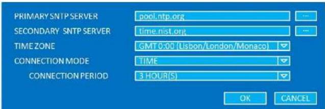
text_image
PRIMARY SNTP SERVER pool.ntp.org SECONDARY SNTP SERVER time.nist.org TIME ZONE GMT 0:00 (Lisbon/London/Monaco) CONNECTION MODE TIME CONNECTION PERIOD 3 HOUR(S) OK CANCELPRIMARY SNTP SERVER: Input the address of the primary NTP time server.
SECONDARY SNTP SERVER: Input the address of the secondary NTP time server.
TIME ZONE: Greenwich Mean Time (GMT) is a term originally referring to mean solar time at the Royal Observatory, Greenwich, London. Because NTP synchronizes with Greenwich Mean Time (GMT) regardless of geography, users must set their own time difference.
CONNECTON MODE: Select NTP time server connection mode.
CONNECTION PERIOD: 1\~24 Hours
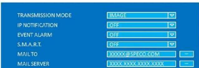
text_image
TRANSMISSION MODE IP NOTIFICATION EVENT ALARM S.M.A.R.T. MAIL TO MAIL SERVER IMAGE OFF OFF XXXXX@SPECO.COM XXXX.XXXX.XXXX.XXXX4-7. Setup – SECURITY
In the SETUP menu, select the SECURITY tab. Then, the SECURITY menu is displayed as pictured below. Navigate through the menu items using the mouse or the control button on the remote control and change the value of the menu item.

text_image
SECURITY USER AUTHENTICATION USER PASSWORD AUTHORITY OF PLAYBACK APPLY CLOSE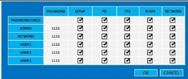
ADMIN, NETOWRK, USER1, USER2, USER3:
Selected Checkbox: The user can access to the function.
Blank Checkbox: The user can not access to the function.
| USER | Options are ADMIN, NETWORK, USER1, USER2 and USER3. |
| PASSWORD | Select USER PASSWORD using the mouse or the control button on the remo control and press SEL button. Select user type and enter the current password. And, enter a new password, enter the same password again to confirm and select OK.Then the message "PASSWORD CHANGED" is displayed.The factory default password is 1111.It is highly recommended to assign a new password to protect the system. |
| AUTHORITY OF PLAYBACK | Select the Checkbox The DVR will ask for a password when the admin/user access to playback mode. |
4-8. Setup - NETWORK
Select the NETWORK tab. Then, the network menu is displayed as pictured below. Navigate through the menu items using the mouse or the control button on the remote control and change the value of the menu.
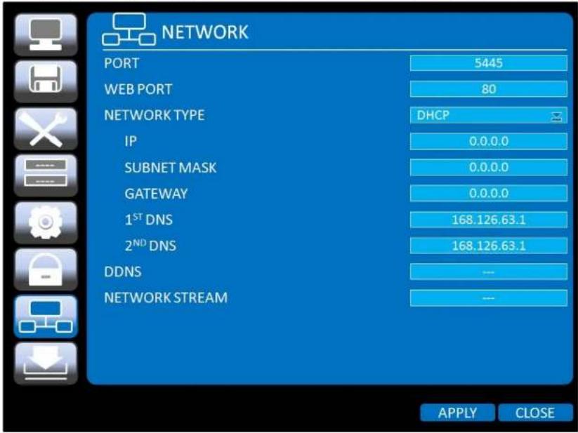
text_image
NETWORK PORT 5445 WEB PORT 80 NETWORK TYPE DHCP IP 0.0.0.0 SUBNET MASK 0.0.0.0 GATEWAY 0.0.0.0 1STDNS 168.126.63.1 2NDDNS 168.126.63.1 DDNS -- NETWORK STREAM -- APPLY CLOSEFigure 4.8.1. NETWORK Setup Screen
4-8-1. Network Types
4-8-1-1. DHCP
An IP address is automatically assigned by the DHCP server, which automatically assigns the IP address and other parameters to new devices.
ADSL and other network types that use a variable IP address method uses this process to acquire an IP address.
4-8-1-2. STATIC
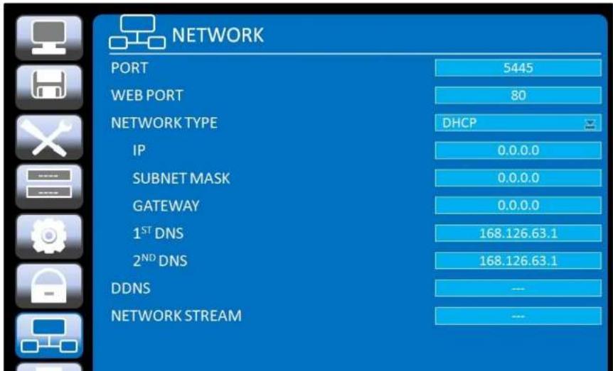
text_image
NETWORK PORT 5445 WEB PORT 80 NETWORK TYPE DHCP IP 0.0.0.0 SUBNET MASK 0.0.0.0 GATEWAY 0.0.0.0 1ST DNS 168.126.63.1 2ND DNS 168.126.63.1 DDNS --- NETWORK STREAM ---4-8-2. DDNS
Dynamic Domain Name System (DDNS) allows a DNS name to be constantly synchronized with a dynamic IP address. It allows those using a dynamic IP address to be associated with a static domain name.
Once the setting is completed, the DDNS address will be:
http://hostname.ddns.specoddns.net
For example, if you enter the host name as "SPECOHD", then the address will be:
http://specohd.ddns.specoddns.net
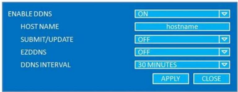
Select NETWORK>DDNS. The menu displays as below.
text_image
ENABLE DDNS ON HOST NAME hostname SUBMIT/UPDATE OFF EZDDNS OFF DDNS INTERVAL 30 MINUTES APPLY CLOSEFigure 4.8.2. Network Setup Screen – DDNS
Table 4.8.2. DDNS
| Item | Description |
FNARI F DDNS
Enable/disable the Dynamic Domain Name Service
4-8-3. Network Port and Web Port
Connecting DVR/DVRs through an IP sharing device, each DVR must be assigned a unique TCP port number for access from outside the LAN. This port number is displayed on NETWORK>NETWORK PORT Setup MENU.

NOTE
If you access the DVR only within the same LAN, the TCP port number does not need to be changed.
Network access beyond a router
To access DVR beyond a router (firewall), you must open the proper TCP ports for live/playback streaming, for commands, for remote backup, and for audio streaming. If these ports are not opened properly, you can not access the DVR beyond a router.

For live/playback streaming, for commands, for remote backup: Open the port number on NETWORK>NETWORK PORT menu. The default port number is 5445.
For bi-directional audio: Open the port number (NETWORK PORT number + 1). If the NETWORK PORT is 5445, open 5446 TCP port.
For web-viewer downloading and remote firmware upgrading: Open the port number on NETWORK>WEB PORT menu. The default port number is 80.
4-8-4. Network Stream
User can set the RESOLUTION, FRAME RATE, and the QUALITY for the network stream.
| ALL | 1 | 2 | 3 | 4 | 5 | 6 | 7 | 8 | |
| RESOLUTION | CIF | CIF | CIF | CIF | CIF | CIF | CIF | CIF | CIF |
| FRAME RATE | 30 | 30 | 30 | 30 | 30 | 30 | 30 | 30 | 30 |
| QUALITY | LELVEL S (H) | LELVEL S (H) | LELVEL S (H) | LELVEL S (H) | LELVEL S (H) | LELVEL S (H) | LELVEL S (H) | LELVEL S (H) | LELVEL S (H) |
4-9. Setup - CONFIG
In the SETUP menu, select the CONFIG tab. Then, the configuration menu is displayed as pictured below. Navigate through the menu items using the mouse or the control button on the remote control and change the value of the menu item.

text_image
CONFIG SAVE SETUP TO A USB LOAD SETUP FROM A USB LOAD DEFAULT LOAD FACTORY DEFAULT --- --- --- --- --- --- APPLY CLOSE | |
| LOADDEFAULT | Press the button to reset the system to the default settings. |
 | |
| The following settings such as Language, DVR ID, Security User Authentication, Security User P/W, Date format, DLS settings, Network settings, HDD overwrite, Limit recording, HDD serial number, and HDB ERROR time will not be included. | |
| LOADFACTORYDEFAULT | Press the button to reset the system to the factory default settings. |
 |
5. Live, Search and Playback
5-1. Live
5-1-1. Main Live Screen and Icon
In the Live screen, video inputs from the cameras are displayed as they are configured in the Display Setup screen. Various On-Screen Display (OSD) symbols, which indicate the status of the DVR, are described in Table 5.1.1.
| CH 2 | CH 3 | CH 4 | |
| CH 5 | CH 6 | CH 7 | CH 8 |
| CH 9 NO VIDEO | SETUP AUDIO SEARCH BACKUP CAMERA PTZ SEQUENCE MANUAL RECORD ALARM OUT HD VIDEO INPUT STATUS CHANNEL INFORMATION SYSTEM INFORMATION SYSTEM LOCK SYSTEM SHUTDOWN | CH 10 NO VIDEO | |

2009/04/14 17:23:40
Event indicator. When there is an event (motion recording, video loss, HDD fail, S.M.A.R.T), this icon will be highlighted bright.
Indicates that a network client is connected to the DVR.
Indicates that sequencing mode is enabled.
RC: ALL
Remote control ID display. If a remote ID is not set, the message "ALL displayed.

15%
Displays the amount of recording on the hard disk from 0-99%.

Indicates that HDD is recycled.

Continuous recording in progress.

Manual recording in progress. To set the Manual recording mode, press the Record button on the front panel.

Motion alarm recording in progress.

Sensor recording in progress.
5-1-2. Quick Operation Window
Table 5.1.2. Quick Operation Window
| Icon | Description |
| SETUP | Setup button. Click this button to go to a setup menu. |
| AUDIO | Audio button. Click this button to set an audio reception type; Audio Mute, 1 channel or 4 channels. To set just 1 channel, select a specific channel on the live screen at first. |
| SEARCH | Search button. Click this button to enter the search menu. |
| BACKUP | Backup button. Click this button to do a back-up. |
| CAMERA PTZ | Camera PTZ button. Opens the PTZ control menu. |
| SEQUENCE | Sequence button. Click this button to use a sequence function. |
| MANUAL RECORD | Manual Record button. Click this button to enable manual recording. |
| ALARM OUT | Alarm-out function On/Off button. Select this button to disable the alarm. |
| HD VIDEO INPUT STATUS | Press the button to view the HDcctv camera input information. |
| Channel 1Total Time 00:01:23Elapsed Time 00:02:23Error Count 0Active Pixels 1280Total Pixels 1650Active Lines 720Total Lines 750Frame Rate 60RESET EXIT | |
| CHANNEL INFORMATION | Press the button to view the record setting of channel. |
5-2. Digital Zoom in Live and Playback Screen
DVR4HD supports Digital Zoom feature during live and playback mode.
- Double click the target channel.

text_image
Comparison of retail store interior photos and product displays, showing front and back views with labeled sections like Q3, Q4, and a red arrow indicating transformation.- Click the left button of the mouse and drag to make rectangular shape.

natural_image
Interior view of a modern exhibition hall with display cases and a close-up of an ancient artifact (no visible text or symbols)5-3. SEARCH Screen
To enter the search screen menu. select SEARCH menu on the screen using the mouse or press SEARCH
5-3-1. TIME-LINE Search
The TIME-LINE search window is used to find the stored video by using the time line bar.

text_image
APR. 2011 SUN MON TUE WED THU FRI SAT 3 4 5 6 7 8 9 10 11 12 12 13 14 16 17 18 19 20 21 22 23 24 25 26 27 28 29 30 <
CLOSE
Figure 5.3.2. Calendar Screen

text_image
04/25/2011 0:00 CH 1 CH 2 CH 3 CH 4 CH 5 CH 6 CH 7 CH 8 15 18 21 245-3-2. Event Search
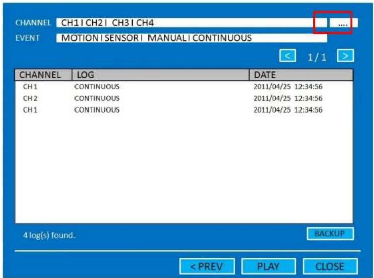
The Event Search window is used to find stored video.
text_image
CHANNEL CH1 | CH2 | CH3 | CH4 .... EVENT MOTION | SENSOR | MANUAL | CONTINUOUS CHANNEL LOG DATE CH1 CONTINUOUS 2011/04/25 12:34:56 CH2 CONTINUOUS 2011/04/25 12:34:56 CH1 CONTINUOUS 2011/04/25 12:34:56 4 log(s) found. BACKUP < PREV PLAY CLOSEFigure 5.3.4. Event Search Screen
When the Event menu is selected, the user can see a calendar which has recorded data. Select a specific date and the event log will be displayed. Press the PLAY button to playback the data or the SAVE button to save the data after selecting the specific data. User can find a data of the specific channel and event using a button in the above red box. Press the PREV to return to the SEARCH window.
5-3-6. Archive Search
The ARCHIVE Search window is used to find previously stored video or images.

text_image
LOG CH1 VIDEO (1mIN) LIVE JPEG PLAY JPEG DATE 2011/04/25 12:34:56 2011/04/25 12:34:56 2011/04/25 12:34:56 3 log(s) found. < PREV DISPLAY CLOSEFigure 5.3.5. Archive Search Screen
When the Archive menu is selected, the user can see a calendar which has recording data. Select a specific date and then the archived data will be displayed. Press the Display button to view the still image or the first frame of the selected video, then the user can save the selected data.
5-3-7. Log Search
You can access the LOG list search screen by selecting LOG on the SEARCH window.

5-4. Play Mode
During playback of a recorded event, the mode changes from SEARCH to PLAY. While in PLAY mode, you may return to the SEARCH screen by pressing the X button on the status bar or the ESC button of a remote control.

natural_image
Interior view of a museum gallery with display cases and glass cases, no visible text or signageFigure 5.4.1. Play Mode Screen
The following status bar hides automatically and appears again when putting a mouse pointer to the bar.
Table 5.4.1. Button Functions in PLAY Mode
Button
Description
6. PTZ Control
To control the PTZ functions of the camera, select PTZ menu on the screen using the mouse. Select the item you wish to control the PTZ camera and control them using the mouse or the control button on the remote control.
Table 6.1. Button Functions in PTZ Control
| Item | Description |
| INITIALIZE | Initialize the PTZ settings of the selected camera. |
| PAN / TILT | Select PAN/TILT using the mouse or the control button and press SEL button on the remote control.Adjust the tilt (UP/DOWN) / pan (LEFT/RIGHT) position using the mouse or the control button on the remote control. |
| ZOOM / FOCUS | Select ZOOM/FOCUS using the mouse or the control button and press SEL button on the remote control.Adjust the zoom (Mouse Wheel Down or Up/Down button of the remote control)/focus (Mouse Wheel Up or Left/Right button of the remote control) position. |
| OSD | Select the OSD to enter the menu. Control keys are Right, Left, UP, Down, Select, Far (REW KEY), and Near (F KEY). Press the ESC button to return to the main menu. Press the PTZ button to escape from the OSD menu. |
| AUTOSCAN | Press the right key on the control button to start auto scanPress the left key on the control button to stop auto scan. |
| PRESET | Select the PRESET and press the left key on the control button. Then number input window will appear. Set the |
7. Back Up
7-1. Still Image Backup onto USB Flash Drive
Still images can be captured and archived onto a USB flash drive or an external hard drive in live mode or while playing back recorded video. In the live mode, press the BACKUP button to launch the archive function or select BACK UP menu on the screen using the mouse.
- Select a specific channel which wants to backup on live screen.
- When you press BACKUP button, the archiving screen will display as Figure 6.1.1.
- Once you press Backup button, the system will capture a still image.

text_image
Please select the media type USB STICK 0% < PRE/ START CLOSEFigure7.1.1. Still Image Archiving and Backup Screen
NOTICE For a backup using a USB Flash Drive, the file format of the USB flash drive must be FAT32.
7-2. Video Backup onto USB Flash Drive
Video can be captured and archived onto the USB flash drive or a hard drive while playing back the recorded video.
In playback mode, press the BACKUP button to launch the backup function.
- When you press BACKUP button, the DVR will ask whether to archive a Still Image or a Video Clip.
- If the user selects VIDEO CLIP, the DVR will ask for the media type. Select USB Stick to back up less than or how. Select USB HDD (Use Backup) to back up from 1 hour to 24 hours.

text_image
CHANNEL ✓ ALL ✓ CH 1 ✓ CH 2 ✓ CH 3 ✓ CH 4 ✓ CH 5 ✓ CH 6 ✓ CH 7 ✓ CH 8 ✓ CH 9 ✓ CH 10 DURATION 1 MINUTE 2011/03/18 11:12:34 - 2011/03/08 11:12:56 < PRE/ BACKUP CLOSEFigure 7.2.1. Video Archiving and Backup Screen
7-3. Transferring Still Images or Video from the ARCHIVE List
The stored data in the hard drive can be found in the ARCHIVE list in the SEARCH window.
User can back up still images or video into the storage device from the ARCHIVE list.
- Select the date to begin searching and navigate through the days using the mouse or the control button or the remote control.
- Once you have selected the date, press the NEXT button to open the list of stored data.
- Use the mouse or the control button on the remote control to scroll through the archive list.
- Select a list of stored events in the archive list.
- Once the desired event has been selected, press the DISPLAY button to view the still image or the first frame of the selected video.
- Press the BACKUP button to launch the archiving function in playback mode.
- Press the CLOSE button to return to the SEARCH window.

text_image
Backup CH 1 VIDEO (1min) 2011/04/26 12:34:56 1 / 1 MEDIA USB BACKUP CLOSEFigure 7.3.1. Archive Search Screen
7-4. Playback of Backup Video
H.264 format video can be played back using the player that the DVR copies on USB flash drive with video. Digital Zoon Feature: Use the mouse scroll to use digital zoom in and out feature.
HD Player

text_image
HD Player CHANNEL 1 00:f2:07:04:00:bb 2011.04.27 / 01:42:44 (DLS) CH01Figure 7.4.1. Playback Screen of HD Player
8. Network Access Using of SpecoTech Multi Client
8-1. Overview
The SpecoTech Multi Client is a multiple site monitoring client software with; video, audio, and alarm signals from the DVRs over networks. The SpecoTech Multi Client does not limit the number of DVR units to register.
The program displays up to 16 DVRs and supports dual monitors.
On the program, user may control PTZF cameras on the DVRs. By attaching a microphone and speaker system to devices on site, the user may make bi-directional audio communication over the network.
8-2. PC Requirements
Minimum PC Requirements
| CPU | Intel Core 2 Duo |
| 1.8Ghz | |
| Memory | 1GB DDR2 |
| VGA | 256MB |
| Resoluon | 1280x720 |
| Disk Space | 1GB |
| OS | Windows 2000, XP Professional, XP Home, Vista, 7 (NOTE: Not all versions of Vista and 7 are supported) |
| Network | 10/100Base T |
| Others | Direct X 8.1 or Higher |
Recommended PC Requirements
| CPU | Intel Core 2 Duo |
| 3Ghz or higher. |
8-3. Installation of the Program
- Insert the provided CD in the CD drive and double-click "SpecoTech Multi Client (XXXX).exe"

SpecoTech_HD
CCTV_Multi_CI
ient 3.0.3.6 11
0414
- Select a destination folder and click "Next".

text_image
InstallShield Wizard Choose Destination Location Select folder where Setup will install files. Setup will install SpecoTech Multi Client in the following folder. To install to this folder, click Next. To install to a different folder, click Browse and select another folder. Destination Folder C:\...\Speco Technologies\SpecoTech Multi Client Browse... < Back Next > Cancel- Select the program folder and click "Next".
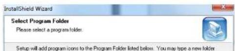
text_image
InstallShield Wizard Select Program Folder Please select a program folder. Setup will add program icons to the Program Folder listed below. You may type a new folder8-4. Live Window
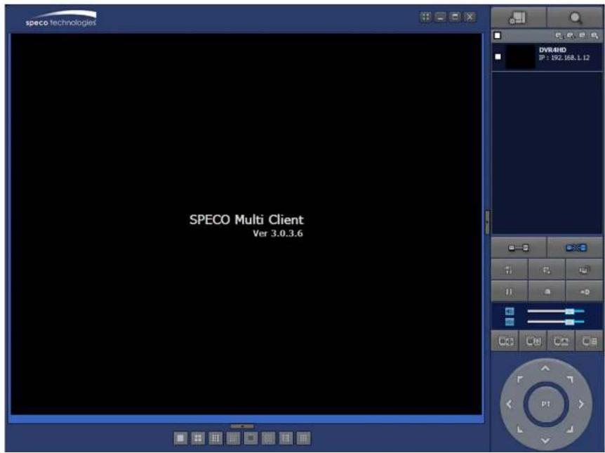
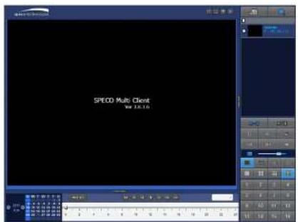
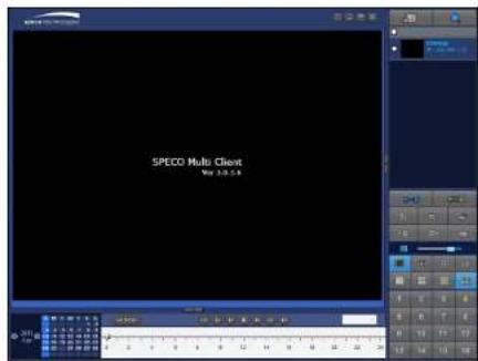
When installation is completed, double click the "SpecoTech Multi Client" icon on your desktop to start the program.
8-4-1. Main User Interface
text_image
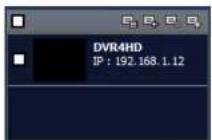
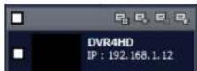
speco technologies SPECO Multi Client Ver 3.0.3.6 DVR:4HD SP : 192.168.1.12 PT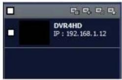 SITE MANAGEMENT SITE MANAGEMENT | THUMBNAIL REFRESH: Click this icon to refresh and renew thumbnail image of the connected sites.SITE ADDITION: Click this icon to open 'Site Addition' window.SITE DELETE: Click this icon to delete site from the index window, after disconnect a site.NET FINDER: Select the site from the index window and click this icon to modify the information of specific site. | |
 | CONNECT | Click this icon to connect the selected site/sites. |
 | DISCONNECT | Click this icon to disconnect the selected site/sites. |
 | SETUP | Click this icon to setup configuration of UMS MULTI CLIENT. |
 | CAPTURE | Click this icon to capture a still image. |
 | EVENT LIST | Opens list of events logged by the UMS Multi Client. |
 | PAUSE | Click this icon to play/pause live video. |
 | ALARM ON | Click this icon to turn on/off alarm outputs. |
8-5. Search and Playback Window
8-5-1. Main User Interface
You can access to search window by clicking the search icon (Local Playback / Remote Playback) on the upper left of the Live Window.

text_image
SPECO Multi Client Ver 3.0.3.6 | THUMBNAIL REFRESH: Click this icon to refresh and renew thumbnail image of the connected sites.SITE ADDITION: Click this icon to open 'Site Addition' window.SITE DELETE: Click this icon to delete site from the index window, after disconnect a site.NET FINDER: Select the site from the index window and click this icon to modify the information of specific site. | |
 | CONNECT | Click this icon to connect the selected site/sites. |
 | DISCONNECT | Click this icon to disconnect the selected site/sites. |
 | SETUP | Click this icon to setup configuration of SpecoTech Multi Client |
 | CAPTURE | Click this icon to capture a still image. |
 | EVENT LIST | Opens list of events logged by the UMS Multi Client. |
 | MARK IN | Click this icon to set the beginning time for backup of the recorded video in AVI format. |
 | MARK OUT | Click this icon to set the ending time for backup of the recorded video in AVI format. |
[EMPTY]
 | To display the recorded data of selected channel or all channels on a time line scale. |
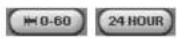 | To change a timeline scale from 24 hours to 60 minutes.The timeline shows recorded data in color on the bar. You can adjust the timeline scale and move it to the time you wish to playback. Then click the play icon to display the recorded video. |
 | Playback buttons. |
 | Digital Zoom Window in Live and Playback. (Only available in Single Channel Viewing) |
8-6. Setup of SpecoTech Multi Client
Click the setup icon

window is displayed as below.
to setup the configuration of UMS Multi Client software. The SETUP
8-6-1. General
Security Option: Set a password for security options. Select security options and set a password.
Then when you access any of selected functions, you need to enter the password.
You can also set the save path for capturing and backup
Save Path: Specify the location to save captured still image for Capture and Backup data.
Miscellaneous
Automatic Reconnection: If enabled, the software will automatically try to reconnect to the last successful IP address. But, when CLIENT ACCESS is OFF on the DVR, the software will not try to reconnect even if it is enabled.
Always On Top: If enabled, the software display will be continuously on the top of other windows.
Time Format: Change the way the Client software displays the time.

text_image
Setup General Event Event search Record Disk Display About Security Option Startup Shutdown Setup Local Playback Remote Playback Password... Save Path Capture : C:\Storage\Capture\ Backup : C:\Storage\Backup\8-6-2. Event
Event log can be archived and searched.
Event Log: Specify the location to save event logs and select event to archive.
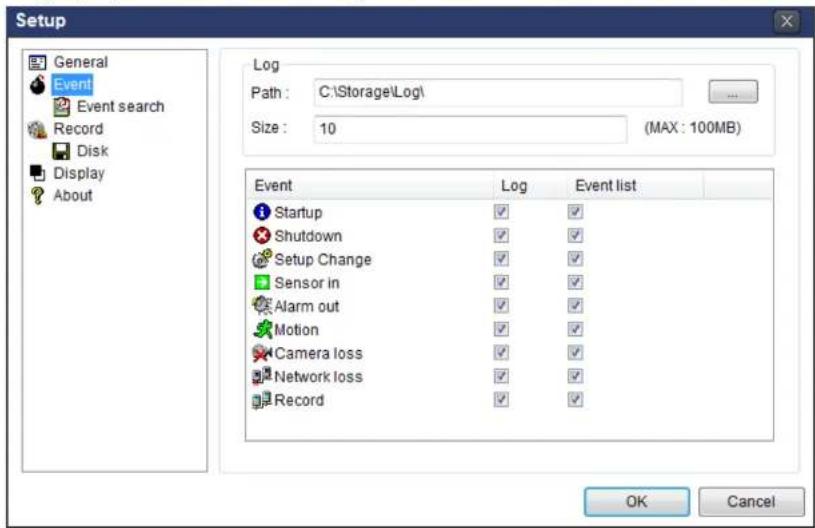
text_image
Setup General Event Event search Record Disk Display About Log Path: C:\Storage\Log\ Size: 10 (MAX: 100MB) Event Log Event list Startup ✓ ✓ Shutdown ✓ ✓ Setup Change ✓ ✓ Sensor in ✓ ✓ Alarm out ✓ ✓ Motion ✓ ✓ Camera loss ✓ ✓ Network loss ✓ ✓ Record ✓ ✓ OK CancelEvent Search: Event log can be searched from selected time.

text_image
Setup General From: First 2011-04-26 12:00:00 AM8-6-3. Record
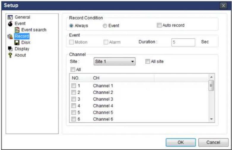
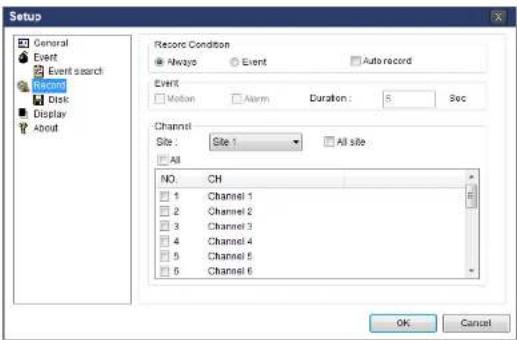
Record Setup: You can set the recording conditions as the following; Always, Event, or Auto record. And you can also select target DVR/DVRs and channel/channels. When you set the recording condition to event, you can set event for motion or alarm with duration.
text_image
Setup General Event Event search Record Disk Display About Record Condition Always Event Auto record Event Motion Alarm Duration: 5 Sec Channel Site : Site 1 All site All NO. CH 1 Channel 1 2 Channel 2 3 Channel 3 4 Channel 4 5 Channel 5 6 Channel 6 OK CancelRecord Local Storage Setup: You can select the local disk to record and the amount of disk space you want to allow the program to use for recording. You can also select the option to overwrite data or stop recording when the maximum amount of disk space is full.

text_image
Setup8-6-4. Display
You can select the OSD (On Screen Display) to be displayed.
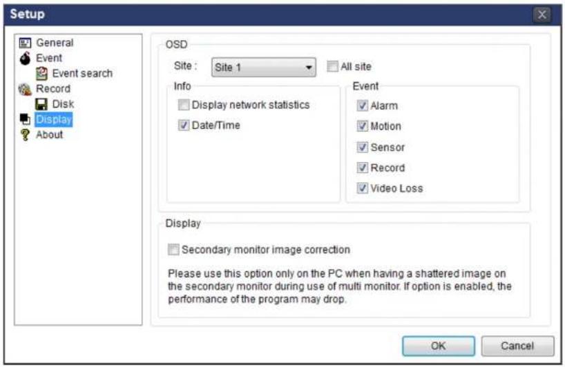
text_image
Setup General Event Event search Record Disk Display About OSD Site : Site 1 All site Info Display network statistics Date/Time Event ✓ Alarm ✓ Motion ✓ Sensor ✓ Record ✓ Video Loss Display Secondary monitor image correction Please use this option only on the PC when having a shattered image on the secondary monitor during use of multi monitor. If option is enabled, the performance of the program may drop. OK Cancel8-6-5. About
English, French and Spanish is selectable.

text_image
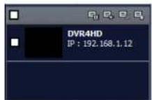
Setup General P 100%8-7. Remote Setup
The menu settings for the DVR unit can be set over network.
Put the cursor of the mouse on the channel which is connected to the site and right click on the mouse to open the submenu. Then the following window is displayed as below. Select the REMOTE SETUP.

text_image
speco technologies 2017-04-07 20:08 SPECO Multi Client Ver 3.0.3.6 SPECO Multi Client Ver 3.0.3.6 SPECO Multi Client Ver 3.0.3.6 SPECO Multi Client Ver 3.0.3.6 SPECO Multi Client Ver 3.0.3.6 SPECO Multi Client Ver 3.0.3.6 SPECO Multi Client Ver 3.0.3.6 SPEKO Multi Client Ver 3.0.3.6 SPECO Multi Client Ver 3.0.3.6 SPECO Multi Client Ver 3.0.3.6 SPECO Multi Client Ver 3.0.3.6 SPECO Multi Client Ver 3.0.3.6 SPECO Multi Client Ver 3.0.3.6 SPECO Multi Client Var 3.0.3.6 SPECO Multi Client Var 3.0.3.6 SPECO Multi Client Var 3.0.3.6 SPECO Multi Client Var 3.0.3.6 SPECO Multi Client Var 3.0.3.6 SPECO Multi Client Var 3.0.3.6 SPECO Multi Client Var 3.1.18-7-1. Display
Select the DISPLAY tab to set the DISPLAY conditions.

text_image
Remote setup WEB SETUP (ver 1.13) DISPLAY RECORD DEVICE STORAGE SYSTEM NETWORK UPGRADE OSD ON OFF OSD CONTRAST 100 SEQUENCE ON OFF SEQUENCE-DWELL TIME 3 SECOND(S) CHANNEL CH1 NAME CH1 COVERT OFF RELOAD APPLYThese settings apply to all channels.
OSD: Sets whether to display or not date and time as well as channel number on the screen.
OSD Contrast: Adjust the character contrast on the screen.
Sequence: Setting for automatically switching the displayed video.
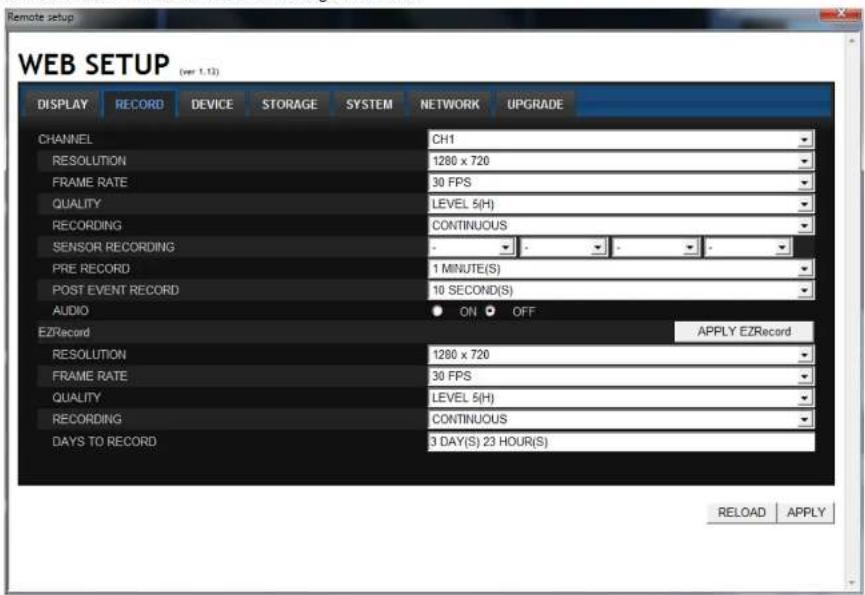
8-7-2. Record
Select RECORD tab to set the recording conditions.
text_image
Remote setup WEB SETUP (ver 1.13) DISPLAY RECORD DEVICE STORAGE SYSTEM NETWORK UPGRADE CHANNEL CH1 RESOLUTION 1280 x 720 FRAME RATE 30 FPS QUALITY LEVEL 5(H) RECORDING CONTINUOUS SENSOR RECORDING - PRE RECORD 1 MINUTE(S) POST EVENT RECORD 10 SECOND(S) AUDIO ON OFF EZRecord APPLY EZRecord RESOLUTION 1280 x 720 FRAME RATE 30 FPS QUALITY LEVEL 5(H) RECORDING CONTINUOUS DAYS TO RECORD 3 DAY(S) 23 HOUR(S) RELOAD APPLYThese settings apply to the specified channel only.
Channel Designation
Resolution: Sets the resolution for the recordings. The set value applies to an individual channel.
Frame Rate: Sets the recording rate.
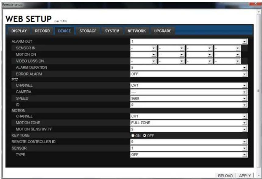
8-7-3. Device
Select Device to set the motion zone, sensor input/alarm output conditions, PTZ control and spot setting conditions.
text_image
Remote setup WEB SETUP (ver 1.13) DISPLAY RECORD DEVICE STORAGE SYSTEM NETWORK UPGRADE ALARM-OUT SENSOR IN MOTION ON VIDEO LOSS ON ALARM DURATION ERROR ALARM PTZ CHANNEL CH1 CAMERA —— SPEED 9600 ID 0 MOTION CHANNEL CH1 MOTION ZONE FULL ZONE MOTION SENSITIVITY 9 KEY TONE ON OFF REMOTE CONTROLLER ID 0 SENSOR 1 TYPE OFF RELOAD APPLYAlarm Output: Sets the alarm output conditions.
Alarm out No.: Specifies the alarm output terminal number (1\~4)
Sensor In: Outputs an alarm signal when the specified sensor terminal receives an input.
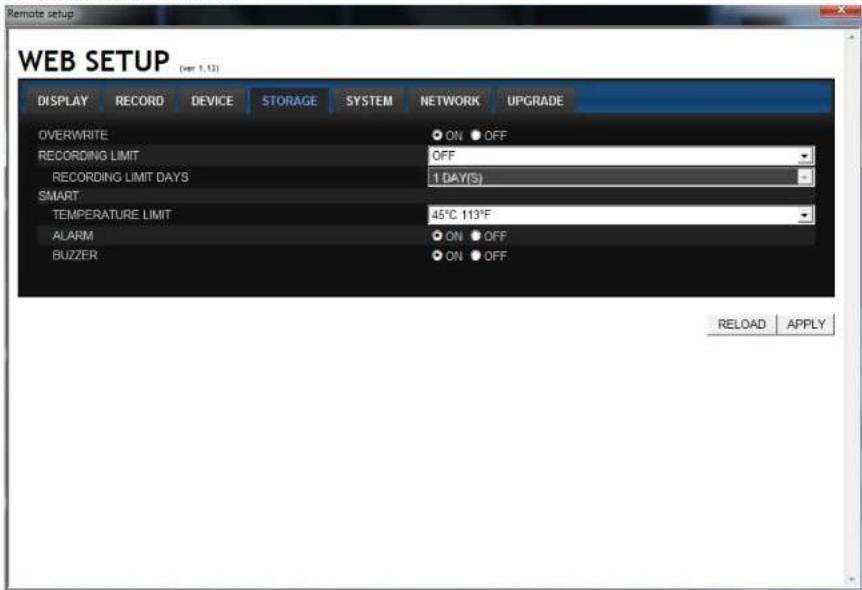
8-7-4. Storage
Select Storage to configure continued recording settings by overwriting the hard disk and the storage period for the recording data.
text_image
Remote setup WEB SETUP (per 1.12) DISPLAY RECORD DEVICE STORAGE SYSTEM NETWORK UPGRADE OVERWRITE ON OFF RECORDING LIMIT OFF RECORDING LIMIT DAYS 1 DAY(S) SMART TEMPERATURE LIMIT 45°C 113°F ALARM ON OFF BUZZER ON OFF RELOAD APPLYOverwrite: To continue recording by overwriting when the hard disk becomes full, check the checkbox.
Record Limit: Sets whether to limit or not the recording data storage period.
Record Limit Davs: Sets a recording data storage period.
8-7-5. System
Select System to set system and time settings.
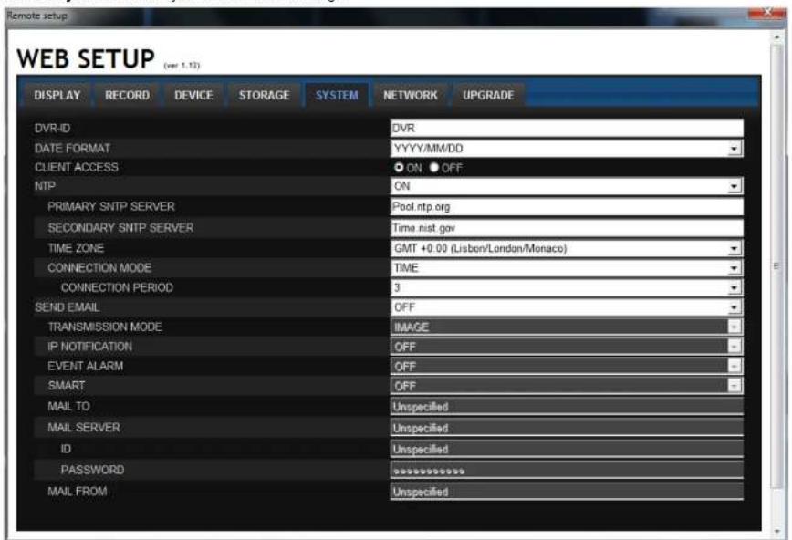
text_image
Remote setup WEB SETUP (ver 1.13) DISPLAY RECORD DEVICE STORAGE SYSTEM NETWORK UPGRADE DVR-ID DVR DATE FORMAT YYYY/MM/DD CLIENT ACCESS ON OFF NTP ON PRIMARY SNTP SERVER Pool.ntp.org SECONDARY SNTP SERVER Time.nist.gov TIME ZONE GMT +0.00 (Lisbon/London/Monaco) CONNECTION MODE TIME CONNECTION PERIOD 3 SEND EMAIL OFF TRANSMISSION MODE IMAGE IP NOTIFICATION OFF EVENT ALARM OFF SMART OFF MAIL TO Unspecified MAIL SERVER Unspecified ID Unspecified PASSWORD ********** MAIL FROM UnspecifiedDVR ID: Sets individual designation to DVRs.
Date Format: Select the date display format
YYYY/MM/DD, MM/DD/YYYY, DD/MM/YYYY, YYYY-MM-DD,MM-DD-YYYY, DD-MM-YYYY
NTP: Sets whether to synchronize the time using NTP server or not.
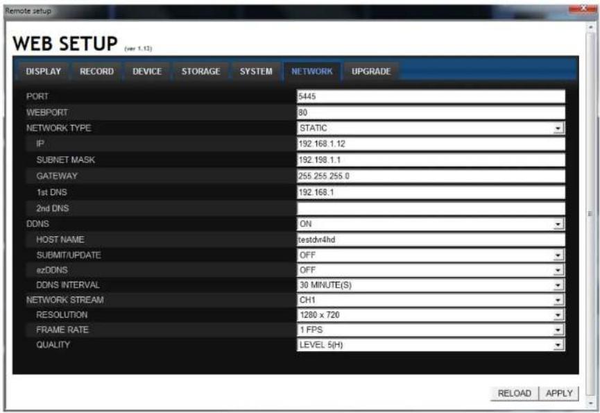
8-7-6. Network
text_image
Remote setup WEB SETUP (see 1.12) DISPLAY RECORD DEVICE STORAGE SYSTEM NETWORK UPGRADE PORT 5445 WEBPORT 80 NETWORK TYPE STATIC IP 192.168.1.12 SUBNET MASK 192.198.1.1 GATEWAY 255.255.255.0 1st DNS 192.168.1 2nd DNS DDNS ON HOST NAMEaledvr4hd SUBMIT/UPDATE OFF ezDDNS OFF DDNS INTERVAL 30 MINUTE(S) NETWORK STREAM CH1 RESOLUTION 1280 x 720 FRAME RATE 1 FPS QUALITY LEVEL 5(H) RELOAD APPLYPort: When connecting multiple DVRs to the network, set a unique port number to each DVR.
Web Port: Set a web server port number.
Network Type
STATIC: The address setting mode is manual. Input IP, Gateway, Subnet Mask, and DNS server IP.
DHCP: The address setting mode is automatic. Addresses and other information do not need to be set.
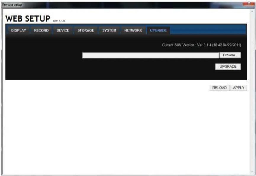
8-7-7. Remote Upgrade
text_image
Remote setup WEB SETUP (ver 1.13) DISPLAY RECORD DEVICE STORAGE SYSTEM NETWORK UPGRADE Current S/W Version : Ver 3.1.4 (18:42 04/22/2011) Browse... UPGRADE RELOAD APPLYBrowse: Select BROWSE to locate the firmware file.
Upgrade: Select UPGRADE to upgrade the firmware of the DVR.
8-8. Operation
8-8-1. Addition, Delete, and Modify of DVR Sites
8-8-1-1. Addition of Sites
- Click SITE ADDITION button. And then the following window will be displayed as below.

text_image
Site Addition Site Info Site Name: DVR4HD Site Address: 192.168.1.12 Port Number: 5445 ID: admin Password: ***** OK Cancel- Site Name: Input a name that properly describes a site.
c IP Address: Input IP address (Public IP address of a router that DVR is connected.) or Domain name - Port Number. Default Port Number is "5445".
c ID: Input ID of DVR. Default ID is "admin". -
Password: Input network password of DVR. Default Password is "1111".
-
Click OK button. And then the registered site is added on the directory window.
8-8-1-3. Modify of Sites
- Select the site/sites to modify from the directory window.
- Click NET FINDER button. And then the following window will be displayed as below.

text_image
Net Finder Name Address H: 264 DVR 102.168.1.16 Address Base Port Mac Model Add Modify Delete Find IP Change Close- Click MODIFY button. And then the modified information is applied.

8-8-2. Connect and Disconnect
8-8-2-1. Connect
- Select site/sites to connect from the directory window.
- Click CONNECT button, and then site/sites displays/display as connected.

text_image
Screenshot of a surveillance camera interface with four identical frames showing outdoor scenes and Chinese UI elements.8-8-2-2. Disconnect
- Select site/sites to disconnect from the directory window.
8-8-3. Still-image Capture during Live
- Double-click a channel to capture from the display screen. (Otherwise all channels will be captured.).
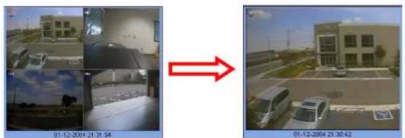
text_image
01-12-2004 21:31:54 01-12-2004 21:30:42
- Click CAPTURE button. And then a Capture window will be displayed as below.
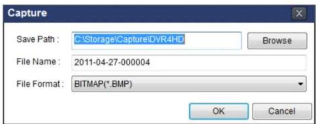
text_image
Capture Save Path : C:\Storage\Capture\DVR4HD File Name : 2011-04-27-000004 File Format : BITMAP(*.BMP) Browse OK Cancel- Set Save path, File Name, and File Format. And then click OK button.
- Still image is saved as set in Capture window.
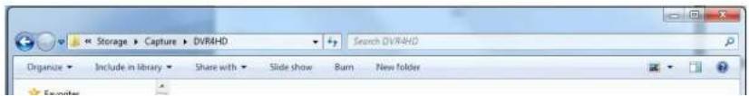
text_image
Storage Capture DVR4HD Search DVR4HD Organize Include in library Share with Slide show Burn New folder8-8-4. Recording Video on Local PC during Live
- Click SETUP button. And then a setup window will be displayed as below.
- Select Record and set the values.
text_image
Setup General Event Event search Record Disk Display About Record Condition Always Event Auto record Event Motion Alarm Duration: 5 Sec Channel Site: Site 1 All site All NO: CH 1 Channel 1 2 Channel 2 3 Channel 3 4 Channel 4 5 Channel 5 6 Channel 6 OK Cancel- Select Disk and set the values.

text_image
Setup General Event Event search Record Case Display About Disk Space: C:\ 4 SD Disk Info Total space: 465 GB Free space: 308 GB Disk full Replace oldest files Stop recording8-8-5. Local Playback and Remote Playback
8-8-5-1. Playback of recorded video on local PC
- Click LOCAL PLAYBACK. And then Playback Window will be displayed over the Live
Window.
text_image
SPEED Multi Client Win: 35.10-
Select site/sites to connect from the directory window.
-
Click CONNECT button. And then Green bar displays on Search calendar and timeline scale
window.

text_image
2011 April M T W T E S 3 4 5 6 7 8 9 10 11 12 13 14 15 16 16 17 18 19 20 21 22 23 24 25 26 27 28 29 30 0 2 4 6 8 10 12 14 16 18 20 22 24- Move the marker on the timeline scale to where there is video data and press the PLAY button.

8-8-5-2. Playback of Recorded Video on Remote DVR
- Click REMOTE PLAYBACK. And then Playback Window will be displayed over the Live
Window.
text_image
SPECO Multi Client Vol 3.0.5.8-
Select the site to connect from the directory window.
-
Click CONNECT. And then Green bar displays on Search calendar and timeline scale window.

text_image
2011 Apr S M T W T F S 1 2 9 4 5 6 7 8 9 15 11 12 13 14 15 16 17 18 19 20 21 22 23 24 25 26 27 28 29 30 0 2 4 6 8 10 12 14 16 18 20 22 24- Move the marker on the timeline scale to where there is video data and press the PLAY button.

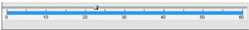
8-8-6. AVI Backup during Playback
You can back up the recorded videos in AVI format during playback.
- Double-click the target channel to backup.
- Select the beginning time by using the search calendar and timeline scale bar.

text_image
S M T W T F S 9 4 5 6 7 8 9 10 11 12 13 14 15 16 17 18 19 20 21 22 23 24 25 26 27 28 29 30 0 2 4 6 8 10 12 14 16 18 20 22 24- Click MARK IN button on the timeline scale to select the beginning point of the backup.
text_image
0 10 20 30 40 50 60- Click MARK OUT button on the timeline scale to select the ending point of the backup. Then, the selected starting point and the ending point on the timeline scale bar will be marked in green.
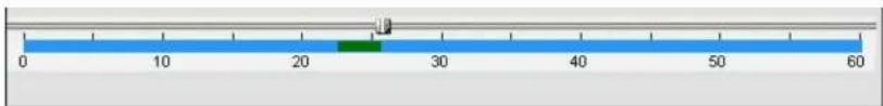
text_image
0 10 20 30 40 50 60- Click BACKUP. And then the BACKUP window will be displayed as below.
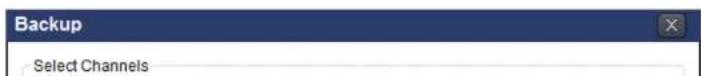
text_image
Backup Select Channels- You can also set the beginning time and ending time on this window. After selecting a channel for backup, click the OK button. The backup will begin.

text_image
Backup Select Channels CH-1 CH-2 CH-3 CH-4 All Setting Start Time: 01:17:18 End Time: 01:19:43 File Path: C:\Storage\Backup\ File format: AVI 7.6% OK Cancel- AVI video data is recorded as set in AVI Backup window. AVI format video can be played back by Window Media Player™ or other media player that is compatible with AVI format video.
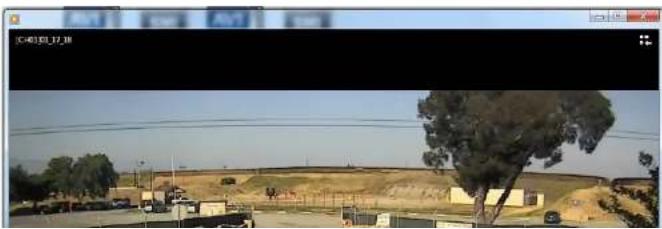
natural_image
Exterior view of a rural landscape with trees, buildings, and a hill under clear sky (no signage or text)9. Network access using the Web-browser Viewer
The DVR provides a live remote monitoring feature by web-browser viewer. (NOTE: Web-Browser is only available for Internet Explorer)
- Check the IP address of the DVR from SETUP>SYSTEM>DESCRIPTION>IP ADDRESS or
- Input the IP address or Domain name address that you pre-registered.

text_image
Address http://172.16.1.52 Go- Click this bar. Then the dialog box is displayed.

- Click "Install" to download and install the ActiveX control.

text_image
User Account Control Do you want to allow the following program to make changes to this computer? Program name: SpecoTech-WebViewer(ver1.4.8.7) Verified publisher: Speco Technologies File origin: Downloaded from the Internet Show details Yes No Change when these notifications appear- The Web Browser Viewer will be displayed as below after the ActiveX installation
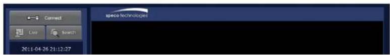
text_image
Connect Live Search 2011-04-26 21:12:27 speco technologies- Click the CONNECT button on the Left upper corner of web-viewer. Then "Connect" dialog is displayed.
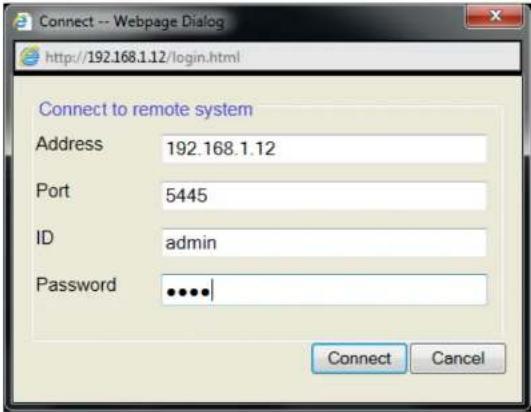
text_image
Connect -- Webpage Dialog http://192.168.1.12/login.html Connect to remote system Address 192.168.1.12 Port 5445 ID admin Password •••••| Connect Cancel- Site Name: Input a name that properly describes a site.
- IP Address: Input IP address (Public IP address of a router that DVR is connected.) or Domain name
• Port Number. Default Port Number is "5445".
• ID: Input ID of DVR. Default ID is "admin". -
Password: Input network password of DVR. Default Password is "1111".
-
Then the cameras connected to the DVR are displayed on the screen.
-
Use mouse scroll to digitally zoom in and out from a single channel display.

10. Network access using the Smart Phone Viewer
10-1. 3G App Viewer for iPhone
- Enter the Apple App Store.

- Search "Speco Viewer" in the App Store.

text_image
iTunes Store Terms and Conditions...
text_image
Info Spegoo Viewer Components Specialties, Inc. No Ratings Space Viewer will ensure the safety of your home and office at anywhere and anytime. Spegoo Viewer DVR list: DV/RHD It is very useful to following customers. - Art-the-art monitoring for a private office located where a lot of people float around - Buildings with easy access of outsiders and cashers - Factory and warehouse monitoring of subdoors entrance - Office and public places - Couples with frequent business trip, leaving old parents and children at home - Homes that use personal safeNotice
SPECO VIEWER is for the DVR4RS, DVR4HD, and DVR82HD. SPECO VIEWER is not compatible with the T Series DVR's (TH, TN or TL) or the PC Series DVR's.
- Install the "Speco Viewer" app.
-
Open the installed "Speco Viewer" App
-
Input the "Site Information" and select Save to save the "Site Information"

text_image
Cancel My Site Site Information Site: My Site IP-0163: Port: 5445 Id: admin Password:- Select the saved site from "My Site List"
- Select a channel (s) to view.

text_image
AT&T 10 10:34 AM Space Viewer Speco Demo Eat Select channels (Max: 4 channels) : 2 3 4 5 6 7 8 9 10 11 12 13 14 15 16 Auto reconnect : ON Connect : Site Information Site: Speco Demo
text_image
ATAT 33 10:35 AM 89% Speco Viewer Speco Demo Edit Select channels (Max. 4 channels) : ✓ ✓ ✓ ✓ 5 6 7 8 9 10 11 12 13 14 15 16 Auto reconnect : ON Connect : Site Information Site: Speco Demo- After selecting a channel, the app will display the channel (s).
10-2. 3G App Viewer for Android Phone
- Enter the Android Market.

- Search "Speco Viewer" in the Android Market and install the "Speco Viewer" app.

My review Let others know what you think of this application.

Description speco viewer will ensure the safety of your house and office at apartment and offices.
Note 1 and Office at Anyofore and Agent
- Open the installed "Speco Viewer" App

text_image
AT&T 3G 10:33 AM 90% speco viewer for iPhone- Input the "Site Information" and select CONFIRM to save the "Site Information"
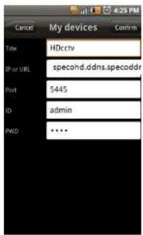
text_image
Cancel My devices Confirm Title HDccty IP or URL specohd.ddns.specoddr Port $445 ID admin PWD ••••- Select the saved site from "My Device" for network connection.
- The app will display the live streaming video.
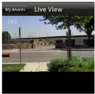
text_image
My devices Live View CH.1APPENDIX: Network Connection - LAN

text_image
IP Router or HUB- Install the network client software from the supplied CD.
- Check the IP address from SETUP>SYSTEM>DESCRIPTION of DVR.
| SOFTWARE VERSION | VER. 1.2.3 (20110425) |
| STORAGE SIZE | 921 GB |
| IP ADDRESS | 192.168.1.80 |
| MAC ADDRESS | 5C.F2.07.04.AA.AA |
| DDNS STATUS | READY (SPECOHD) |
- Run network client software

text_image
space technology 文件(F) D:\2018\1.12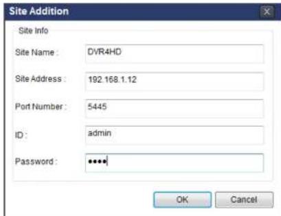
text_image
Site Addition Site Info Site Name: DVR4HD Site Address: 192.168.1.12 Port Number: 5445 ID: admin Password: ****. OK Cancel-
Input Site Name, Site Address (IP address), Port Number, and Password on the connect window.
-
Site Name: Input a name that properly describes a site.
- IP Address: Input IP address (Public IP address of a router that DVR is connected.) or Domain name
• Port Number. Default Port Number is "5445".
• ID: Input ID of DVR. Default ID is "admin". -
Password: Input network password of DVR. Default Password is "1111".
-
Select a site by checking the box, and Press button to connect to the site.
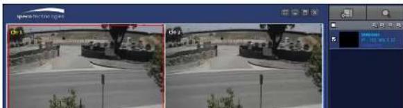
natural_image
Two identical outdoor surveillance cameras showing a road scene with vehicles and buildings, no visible text or symbols.APPENDIX: Network Connection – Internet and DDNS
Dynamic Domain Name System (DDNS) allows a domain name to be constantly synchronized with a dynamic IP address. A current dynamic IP address is being associated with a static domain name.

flowchart
graph LR
    A["Network Device"] -->|Red Line| B["IP Router or HUB"]
    B --> C["ADSL"]
    C --> D["Internet"]
    D --> E["Laptop"]
- Go to SETUP>NETWORK>DDNS and set the DDNS SERVER to ON.
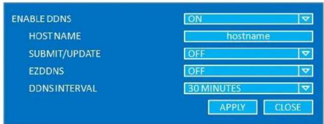
text_image
ENABLE DDNS ON HOST NAME hostname SUBMIT/UPDATE OFF EZDDNS OFF DDNS INTERVAL 30 MINUTES APPLY CLOSE- When manual host name input is done, Go to SETUP>NETWORK>DDNS>SUBMIT/UPDATE and select ON to submit the settings on the SPECO DDNS.
Once the setting is completed, the DDNS address will be: http://hostname.ddns.specoddns.net For example, if you enter the host name as "SPECOHD", then the address will be: http://specohd.ddns.specoddns.net
- When DDNS setting is done, click APPLY button. Otherwise DDNS setting will not be applied.
- When you exit SETUP menu, DDNS Status window will pop up.

text_image
DDNS NOTIFY HOST NAME: SPECOHD STATUS: CUCCEED OK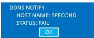
- DDNS registration status can be checked from SYSTEM INFORMATION or SETUP>SYSTEM>DESCRIPTION.
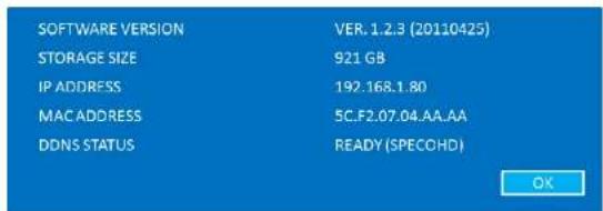
text_image
SOFTWARE VERSION STORAGE SIZE IP ADDRESS MAC ADDRESS DDNS STATUS VER.1.2.3 (20110425) 921 GB 192.168.1.80 5C.F2.07.04.AA.AA READY (SPECOHD) OK-
Check the network PORT (Default: 5445), WEB PORT (Default: 80), and the private IP Address of the DVR from SETUP>NETWORK and SETUP>SYSTEM>DESCRIPTION.
-
And port forward the network PORT (Default: 5445) and WEB PORT (Default: 80) of the private IP Address of the DVR from the network router.

Please refer to the user manual and guide for the detailed steps for port forwarding for spec router model.
- Run network client software.

text_image
SPECO Multi Client Ver 3.0-3.6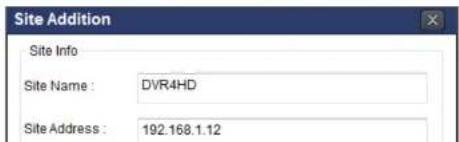
text_image
Site Addition Site Info Site Name : DVR4HD Site Address : 192.168.1.12And select the OK button. Then, press

button after checking the left check box.

text_image
speed monitoring 01-3 02-2 03-3 04-4APPENDIX: E-SATA CONNECTION

Please read the following instructions before using the E-SATA port. Failure to do so may cause serious damage to the recorded video. SPECO is not responsible for data loss caused by improper usage.
- Use ONLY a new HDD or a HDD that is pre-formatted on a PC.
- Turn off the DVR before plugging the E-SATA HDD.
- DO NOT disconnect the E-SATA port while the DVR power is on.
- The purpose of the E-SATA port is to extend recording capacity.
- Once connected, DO NOT remove or disconnect the E-SATA port from the DVR.
- The E-SATA port does not support the hot swappable function.