ZIPT84B2 - Security Camera Speco Technologies - Free user manual and instructions
Find the device manual for free ZIPT84B2 Speco Technologies in PDF.

User questions about ZIPT84B2 Speco Technologies
0 question about this device. Answer the ones you know or ask your own.
Ask a new question about this device
Download the instructions for your Security Camera in PDF format for free! Find your manual ZIPT84B2 - Speco Technologies and take your electronic device back in hand. On this page are published all the documents necessary for the use of your device. ZIPT84B2 by Speco Technologies.
USER MANUAL ZIPT84B2 Speco Technologies
Model: D4VX, D8VX, D16VX
4, 8 & 16 Channel HD TVI Digital Video Recorder
natural_image
Front view of a gray electronic device panel with ports and buttons (no visible text or symbols)Cautions

CAUTION: TO REDUCE THE RISK OF ELECTRIC SHOCK, DO NOT REMOVE COVER (OR BACK). NO USER SERVICEABLE PARTS INSIDE. REFER SERVICING TO QUALIFIED SERVICE PERSONNEL.
Explanation of Graphic Symbols

This symbol indicates the presence of important operating and maintenance (servicing) instructions in the literature accompanying the product.

This symbol indicates the presence of "dangerous voltage" within the product's enclosure that may be of sufficient magnitude to constitute a risk of electric shock, property damage, personal injury, or death.
These Precautions must be followed for Safety Reasons

Warning
- Do not use if the unit emits smoke.
- Do not disassemble the unit.
- Do not place any heavy or sharp objects on the unit.
- Do not place on uneven surface.
- Do not expose to shock or vibration.
- Do not move the unit when the unit is powered on.
- Do not block, and allow dust to accumulate in the air vents.
- Do not restrict airflow of the unit; doing so can damage the unit.
- Only qualified and experienced personnel should perform installation and servicing.
- Turn off the power of the DVR when connecting Cameras, Audio or Sensor Cables.
- The manufacturer is not responsible for any damage caused by improper use of the product or failure to follow instructions for the product.
- The manufacturer is not responsible for any problems caused by or resulting from the user physically opening the DVR for examination or attempting to repair the unit.
Product Components
Please make sure the following components are included as specified below.
| DVR Unit |  |
| Remote Control | 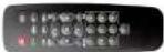 |
| Battery1.5V (AAA x 2EA) |  |
| Quick Start Guide & Quick User Guide |  |
| Mouse |  |
| Software & Manual CD |  |
| Adaptor (DC12V 3A) & Power cable (110V) |  |
Specifications
| MODEL NAME D4VX D8VX D16VX | |||||
| Video Input Number of Channels 4 8 16 | |||||
| Camera Types 960H, HD-TVI 1/2/3/4MP | |||||
| Output Main Monitor VGA and HDMI(Max. 1920x1080)VGA and HDMI(Max. 3840x2160) | |||||
| Sub Monitor CVBS or SPOT (Selectable) | |||||
| Audio Input Local Input 4 | |||||
| Output Local Output1 | |||||
| Audio CodecG.711 | |||||
| Alarm | Sensor In | 4 4 or 8(with Sensor Box)4 or 16(with Sensor Box) | |||
| Alarm Output | 1 | ||||
| Serial RS-232C | None | ||||
| RS-4851 | |||||
| Live | Frame rate with 4M Camera | 15fps/Ch | 15fps/Ch | 15fps/Ch | |
| Frame rate with 3M Camera | 18fps/Ch 18fps/Ch18fps/Ch | ||||
| Frame rate with 2M Camera | 30fps/Ch 30fps/Ch30fps/Ch | ||||
| Recording | Compression | H.264 | |||
| Local Resolution & Frame Rate | 2688x1520(4M) | 10fps/Ch 10fps/Ch12fps/Ch | |||
| 2304x1296(3M) | 13fps/Ch 13fps/Ch15fps/Ch | ||||
| 1920x1080(2M) | 15fps/Ch 15fps/Ch15fps/Ch | ||||
| Recording Quality Grade | 5 Levels | ||||
| Recording Mode | Smart / Continuous / Motion / Sensor / Schedule /Manual | ||||
| Dynamic DNS Yes (Free Speco DDNS) | |||||
| Dual Streaming Yes | |||||
| Features Camera Control OSD and PTZF Control via UTC | |||||
| Network Access | 3G/4G Mobile Viewer Speco Player (iPad / iPhone / Android)) | ||||
| PC Web Viewer Windows (IE, Chrome, Firefox, Safari) | |||||
| PC Client SecureGuard CMS and SpecoTech Multi-Client Viewer | |||||
| Remote Setup and Upgrade Yes | |||||
| Power | Power Supply Voltage | 12V 3A | |||
| Temperature | Operation | 41°F ~ 104°F (5°C ~ 40°C) | |||
| Storage | 14°F ~ 122°F (-10°C ~ 50°C) | ||||
| Humidity | Operation | 20% ~ 80% (Non-condensing) | |||
| Weight | Unit Weight (Gross weight) | Approximately 4.35 lbs | |||
| Dimension | Unit Dimension (W x H x D) | 11.8"(W) x 2.0"(H) x 9.9"(D) | |||
Please note that specifications and unit exterior design are subject to change without notification.
Table of Contents
- Main Features.... 10
- Initial Boot up Process....11
2-1. Initial Boot up and Basic Time Setup.... 11
2-2. Setting Daylight Saving Time 11
2-3. Setting NTP (Network Time Protocol)....13
2-4.EZ Setup....16
- Name, Function and Connection .... 18
3-1. Front Panel 18
3-2. Connectors .... 18
3-3. Remote Control....19
- Setting up the DVR....21
4-1. Setup – Main Live Screen....21
4-2. Setup – System Mode 21
4-2-1. How to use 'Cloud' 26
4-3. Setup – Record Mode 27
4-3-1. Recording Schedules....29
4-4. Setup - Device Mode....29
4-4-1. Digital Deterrent....31
4-4-2. Keyboard Controller & PTZ Setup 32
4-5. Setup – Display Mode 36
4-6. Setup – Network Mode....37
4-6-1. Network Types....38
4-6-2. DDNS 39
4-6-3. Network Port and Web Port....39
5-3-6. Go To Last Time....57
5-3-7. Go To Specific Time....57
5-3-8. Archive List .... 58
5-3-9. Log List....58
5-4. Play Mode....58
- Export and Back Up.... 60
6-1. Still Image Backup onto USB Flash Drive....60
6-2. Video Backup onto USB Flash Drive during playback 61
6-3. EZCopy: Video Backup onto USB Flash Drive during playback....62
6-4. Transferring Still Images or Video from the ARCHIVE List....63
6-5. Playback of Backup Video....64
6-5-1. AVI Format....64
6-5-2. NSF Format....64
- Network Access Using the Multi-Sites Network Viewer....65
7-1. Overview....65
7-2. PC Requirements....65
7-3. Installation of the Program 66
7-4. Live Window....67
7-4-1.Main User Interface....67
7-4-2. Control Buttons....68
7-5. Search and Playback Window....69
7-5-1.Main User Interface....69
7-5-2. Main Control Panel 70
7-5-3. SMART SEARCH 72
7-6-1. General....74
7-6-2. Event 75
7-8-2. Connect and Disconnect....88
7-8-3. Still-image Capture During Live....89
7-8-4. Recording Video on Local PC During Live 90
7-8-5. Local Playback and Remote Playback....91
7-8-6. AVI Backup during Playback 93
-
Network Access Using the Web-Browser Viewer 95
-
Network Access Using the Smart Phone Viewer....97
9-1. App Viewer for iPhone....97
9-1-1. Live 97
9-1-2.PTZ Control 99
9-1-3. Playback....99
9-2. App Viewer for Android Phone....100
9-2-1. Live 100
9-2-2. Playback....101
9-2-3.PTZ Control 102
APPENDIX: Network Connection - LAN 103
APPENDIX: Network Connection – Internet and DDNS....105
1. Main Features
■ Easy Record, Copy and Setup
■ Easy Search by Thumbnail Preview
■ Easy Copy
■ Digital Deterrent function
■ H.264 high quality compression saves HDD space
■ Simultaneous live view/playback while continuing to record/network transfer or backup
■ Remote monitoring/recording/playback/configuration and control via internet
■ 4 Channel Audio Recording
■ Switch between low and high quality stream during simultaneous Continuous + Motion or Continuous + Sensor recording modes for storage optimization
NOTE: Under federal law, The Fourth Amendment to the U.S. Constitution, Title III of the Omnibus Crime Control and Safe Streets Act of 1968, as amended by the Electronic Communications Privacy Act of 1986 (18 U.S.C. § 2510, et seq.), and the Foreign Intelligence Surveillance Act of 1978 (50 U.S.C. 1801, et seq.) permit government agents, acting with the consent of a party to a communication, to engage in warrantless interceptions of telephone communications, as well as oral and electronic communications.
■ Automatic camera detection (Plug & Play)
■ Covert camera operation provides enhanced security and administrator control
■ Dynamically programmable recording priority, motion detection, alarms and scheduling
■ Simple and Easy Graphic User Interface
■ HDMI Output
■ Password to secure access
■ Network software supports 10/100/1000Mbps
■ USB 2.0 port for video clip exporting and easy firmware upgrade via USB Flash Drive
2. Initial Boot up Process
2-1. Initial Boot up and Basic Time Setup
- During the first boot up, the following logo and message will be displayed.

text_image
speco technologies- After the logo, select the language as specified below.

text_image
Choose Language english Close Change Your Password For Cyber Security ! New select Confirm select Password Match ok1) User has to set a password before using.
Can not use '1111' when the initial boot up password set.
But user can set '1111' as a password through [Setup > User Management > Password Setup]
2) DVR will not proceed when user put the password '1111'.
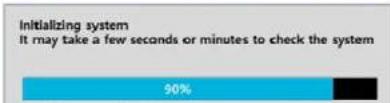
bar
Initializing system It may take a few seconds or minutes to check the system | Category | Value (%) | |---|---| | Initializing system | 90 | | It may take a few seconds or minutes to check the system | (not labeled) |
text_image
Search Setup Display Super EZ Copy Gazio Manual Record Instan: Flushack Advanced Menu EZ Server Xpert Mio Gazio P2 Gazio Main Mechater Sequence Discrete Mouse Out Ankayest Digital Inventory Side instruction System Information System Help System Link System Shockset TechnologiesSearch
Setup
Display
Aspect Ratio
Snapshot
Super EZ Copy
Enable Manual Record
Instant Playback
Advanced Menu
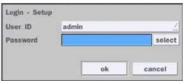
text_image
Login - Setup User ID admin Password select ok cancel- Go to Setup > System > Date & Time Setup
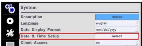
text_image
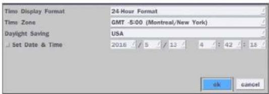
System Description select Language english / Date Display Format mm/dd/yyyy / Date & Time Setup select Client Access on /- Select 'ok" from the Daylight Saving dropdown menu.
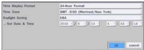
text_image
Time Display Format 24-Hour Format Time Zone GMT -5:00 (Montreal/New York) Daylight Saving USA Set Date & Time 2016 / 5 / 13 / 4 / 42 / 18 ok cancel2-3. Setting NTP (Network Time Protocol)
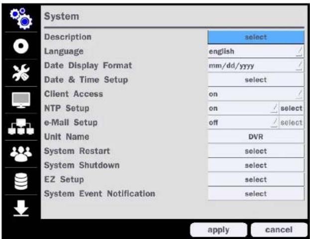
- Setup > System > NTP Setup > On > Select

text_image
System Description select Language english Date Display Format mm/dd/yyyy Date & Time Setup select Client Access on NTP Setup on select e-Mail Setup off select Unit Name DVR System Restart select System Shutdown select EZ Setup select System Event Notification select apply cancelTable 2.3.1. GMT Time Zone
| State | Standard Time Daylight-Saving | Time | |
| AL Alabama GMT-6 GMT-5 | |||
| AK Alaska GMT-9 GMT-8 | |||
| AK Alaska (Aleutian Islands) GMT-10 | NA | ||
| AZ Arizona GMT-7 | NA | ||
| AZ Arizona (Navajo) | GMT-7 GMT-6 | ||
| AR | Arkansas | GMT-6 GMT-5 | |
| CA | California | GMT-8 GMT-7 | |
| CO | Colorado | GMT-7 GMT-6 | |
| CT | Connecticut | GMT-5 GMT-4 | |
| DC | District of Columbia | GMT-5 GMT-4 | |
| DE | Delaware | GMT-5 GMT-4 | |
| FL Florida | GMT-5 | GMT-4 | |
| FL | Florida (W) | GMT-6 GMT-5 | |
| GA | Georgia | GMT-5 GMT-4 | |
| HI | Hawaii | GMT-10 | NA |
| ID | Idaho (N) | GMT-8 GMT-7 | |
| ID | Idaho (S) | GMT-7 GMT-6 | |
| IL | Illinois GMT-6 | GMT-5 | |
| IN Indiana | GMT-5 | GMT-4 | |
| IN | Indiana (SW / NW) | GMT-6 | GMT-5 |
| IA | Iowa | GMT-6 GMT-5 | |
| KS | Kansas | GMT-6 GMT-5 | |
| KS | Kansas (W) | GMT-7 GMT-6 | |
| NH New Hampshire GMT-5 GMT-4 | |||
| NJ New Jersey GMT-5 GMT-4 | |||
| NM New Mexico GMT-7 GMT-6 | |||
| NY New York GMT-5 GMT-4 | |||
| NC North Carolina GMT-5 GMT-4 | |||
| ND North Dakota GMT-6 GMT-5 | |||
| ND | North Dakota (W) | GMT-7 GMT-6 | |
| OH Ohio | GMT-5 | GMT-4 | |
| OK | Oklahoma | GMT-6 GMT-5 | |
| OR Oregon | GMT-8 | GMT-7 | |
| OR Oregon (E) | GMT-7 | GMT-6 | |
| PA Pennsylvania GMT-5 GMT-4 | |||
| RI | Rhode Island GMT-5 | GMT-4 | |
| SC | South Carolina | GMT-5 GMT-4 | |
| SD | South Dakota (E) | GMT-6 GMT-5 | |
| SD | South Dakota (W) GMT-7 | GMT-6 | |
| TN Tennessee (E) | GMT-5 | GMT-4 | |
| TN | Tennessee (W) | GMT-6 GMT-5 | |
| TX | Texas | GMT-6 GMT-5 | |
| TX | Texas (W) | GMT-7 GMT-6 | |
| UT | Utah | GMT-7 GMT-6 | |
| VX | Vermont | GMT-5 GMT-4 | |
| VA | Virginia | GMT-5 GMT-4 | |
| WA | Washington | GMT-8 | GMT-7 |
| WV | West Virginia GMT-5 | GMT-4 | |
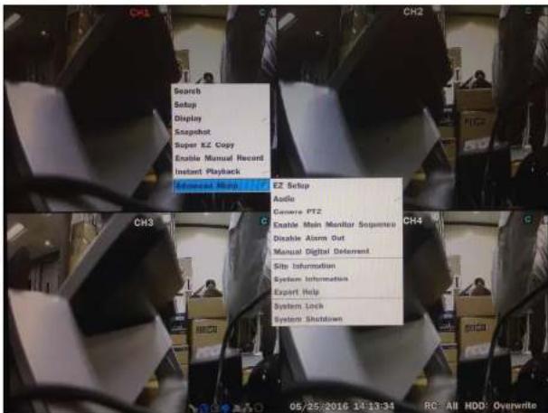
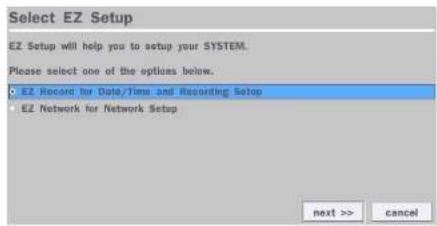
2-4. EZ Setup
VX Easy Setup(Click the right button on mouse > Advanced Menu > EZ Setup)
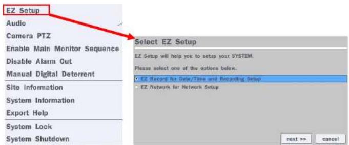
text_image
EZ Setup Audio Camera PTZ Enable Main Monitor Sequence Disable Alarm Out Manual Digital Detorrent Site Information System Information Export Help System Lock System Shutdown Select EZ Setup EZ Setup will help you to setup your SYSTEM. Please select one of the options below. EZ Record for Data/Time and Recording Setup EZ Network for Network Setup next >> cancelFigure 2.4. EZ Setup Screen
2.4.1. Setup Date/Time and Recording configuration
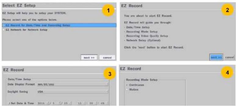
text_image
Select EZ Setup EZ Setup will help you to setup your SYSTEM. Please select one of the options below. • EZ Record for Item/Time and Recording Setup • EZ Network for Network Setup next >> cancel EZ Record You are about to start EZ Record. EZ Record will guide you through: • Date/Time Setup • Recording Mode Setup • Recording Window Quality Setup • Network Setup (Optional) Click the 'next' button to start EZ Record. next >> cancel EZ Record Date/Time Setup Date Display Format mm/dd/yyyy Daylight Saving USA Set Date & Time 2016 / 5 / 25 13 58 45 EZ Record Recording Mode Setup • Continuous • Motion2.4.2. EZ Network (Using an internet connection)
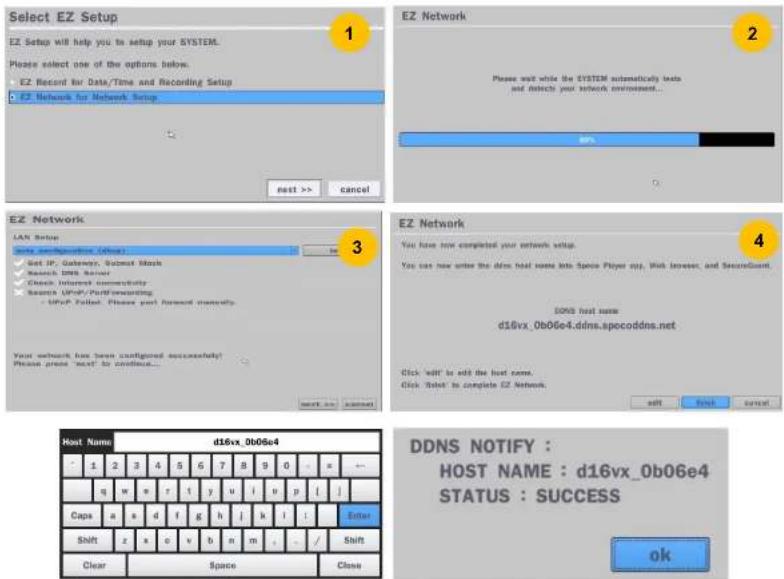
Figure 2.4.2. EZ Network Setup Procedure
① DVR automatically checking the network and configuration by scanning in few seconds.
② DVR will show the DDNS host name when configuration is finished automatically.
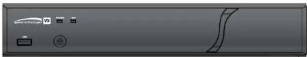
3. Name, Function and Connection
3-1. Front Panel

text_image
Device Technology POWER USB Power USBFigure 3.1.1. Front panel
Table 3.1.1. Front LED and Port of DxxVX
| Name Description |
| POWER LED light is on when power is applied to the system. |
| HDD LED light is on when the system is recording video data. |
| USB Port This USB port for archiving footage into a USB device. (USB 2.0 connector) |
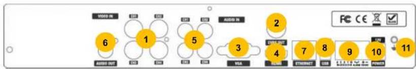
3-2. Connectors
flowchart
graph TD
    A["6 AUDIO OUT"] --> B["1"]
    B --> C["5"]
    C --> D["3"]
    D --> E["2"]
    E --> F["4"]
    F --> G["7"]
    G --> H["8"]
    H --> I["9"]
    I --> J["10"]
    J --> K["11"]
    style A fill:#fff,stroke:#000
    style K fill:#fff,stroke:#000
    style B fill:#fff,stroke:#000
    style C fill:#fff,stroke:#000
    style D fill:#fff,stroke:#000
    style E fill:#fff,stroke:#000
    style F fill:#fff,stroke:#000
    style G fill:#fff,stroke:#000
    style H fill:#fff,stroke:#000
    style I fill:#fff,stroke:#000
    style J fill:#fff,stroke:#000
    style K fill:#fff,stroke:#000
D4VX

① VIDEO IN: Video input port.
② VIDEO OUT: CVBS – Composite Video Output / SPOT – Spot Monitor
③ VGA: VGA (Video Graphics Array) output port. Connects to the PC VGA monitor.
④ HD VIDEO OUT: HDMI Video Output, Connections to the HDMI monitor (D4VX & D8VX: Max.1920x1080, D16VX: Max.3840x2160).
⑤ AUDIO IN: Four connectors for audio input.
⑥ AUDIO OUT: One connector for audio output.
⑦ ETHERNET: Network terminal
⑧ USB: USB terminal
⑨ SENSOR IN, ALARM OUT, RS-485: External sensor terminal, External alarm out terminal & RS-485 for PTZ Camera control
⑩ POWER: DC12V input
⑪ Ground: Use for ground port
3-3. Remote Control

text_image
1 2 3 4 5 6 7 8 9 10 11 12 13 14 SET BACKUP SET SET SET SET SET SET SET SET SET SET SET SET SET SET SET SET SET SET- During Playback – To exit playback mode
- System lock – To lock a system when pressing ESC button for 5 seconds.
- System unlock – To unlock a system when pressing ESC button for 5 seconds.
⑩ SETUP: To open the SETUP menu.
⑪ Direction buttons: To move menu items or select a channel.
⑫ SEQ: To start auto sequencing the screen in full screen mode. (Toggle)
⑬ BACKUP: To start a backup operations in live or playback mode
⑭ 0\~9: To select channel (1,2,3,...) or to enter a DVR ID number or use as number key.
4. Setting up the DVR
The following sections detail the initial setup of the DVR.

Menu screen will close if user input is not received in 5 minutes.
4-1. Setup - Main Live Screen
To enter the setup menu, right click on the mouse and select setup from the submenu or press the setup button on the remote control.
text_image
Search Setup Display Snapshot Super EZ Copy Enable Manual Record Instant Playback E2 Setup Audio Generic PT2 Enable Main Monitor Sequence Disable Alarm Out Manual Digital Delement Site Information System Information Export Help System Lock System ShutdownFigure 4.1.1. Live Screen and Quick Operation Window
text_image
System Description select Language english Date Display Format mm/dd/yyyy Date & Time Setup select Client Access on NTP Setup on select e-Mall Setup off select Unit Name DVR System Restart select System Shutdown select EZ Setup select System Event Notification select apply cancelFigure 4.2.1. System Setup Screen
Table 4.2.1. Menu Items in System Setup Screen
Item Description
| Description | Press "select" to view the system information. (Software Version, Storage Size, IP Address, MAC Address and DDNS Status) |
| Model Name | D16VX |
| Software Version | Ver 5.3.1N_20161209 |
| Storage Size | 3645 GB |
text_image
Time Display Format 24 Hour Format Time Zone GMT -5:00 (Montreal/New York) Daylight Saving USA Set Date & Time 2016 / 5 / 13 / 4 : 42 : 18 ok cancelSelect Daylight Saving using the mouse or the remote control and select the appropriate daylight saving time zone. The options are:
OFF: Daylight saving is turned off.
USA: Applies the USA daylight saving time.
EU: Applies the EU daylight saving time.
- Select the GMT AREA using the mouse or the remote control.
- Set the time difference with the standard time.
OTHERS: If the time zone is neither USA nor EU, set the date and time of the daylight saving period.
- Select BEGIN or END using the remote control and press the "ok" button.

Caution
- Do not set the start time to 23:00 for DLS.
- DLS cannot be applied if the date of BEGIN and END is the same.
Client Access Enable/Disable remote access through the network.
NTP
Setup
NTP (Network Time Protocol) which synchronizes the time of the computer systems over variable-latency data networks.
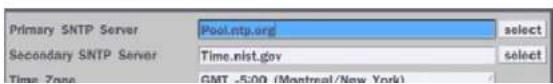
text_image
Primary SNTP Server Pool.ntp.org select Secondary SNTP Server Time.nist.gov select Time Zone GMT -5:00 (Montreal/New York)Connection Mode.

DVR sends e-Mail Notification when the NTP server time is faster than the system time with bellow message.
"NTP server time is faster than the system time."
In this case, NTP server time is ignored to protect the user data.
User must set the time manually.
System Time: Mon Oct 10 13:46:49 2011
Server Time: Mon Oct 10 13:33:12 2011
DVR ID: DVR
IP ADDRESS: 172.16.2.46"
e-Mail Setup
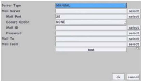
text_image
Server Type MAIL Server mail Port Secure Option mail ID Password mail To mail From MANUAL select 25 NONE select select select select select test ok cancelServer Type: MANUAL, GMAIL, HOTMAIL, AOL or YAHOO
Mail Server: Enter the appropriate mail server information.
Mail Port: Assign Mail Port number.
text_image
Select EZ Setup EZ Setup will help you to setup your SYSTEM. Please select one of the options below. • EZ Record for Date/Time and Recording Setup • EZ Network for Network Setup next >> cancelSystem Event Notification
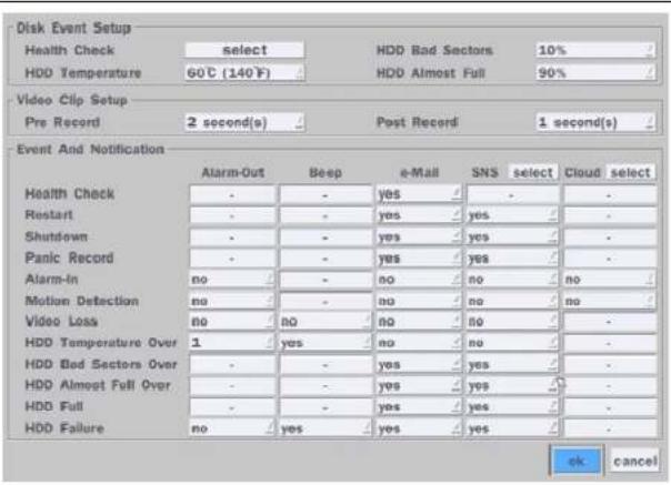
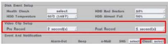
text_image
Disk Event Setup Health Check select HDD Bad Sectors 10% HDD Temperature 60°C (140°F) HDD Almost Full 90% Video Clip Setup Pre Record 2 second(s) Post Record 1 second(s) Event And Notification Alarm-Out Beep e-Mail SNS select Cloud select Health Check - - yes - - - Restart - - yes - yes - - Shutdown - - yes - yes - - Panic Record - - yes - yes - - Alarm-In no - - no - no - no - Motion Detection no - - no - no - no - Video Loss no - no - no - - HDD Temperature Over 1 yes - no - no - - HDD Bad Sectors Over - - yes - yes - - HDD Almost Full Over - - yes - yes - - HDD Full - - yes - yes - - HDD Failure no yes yes yes - - ok cancelHealth Check
(Allows the user to set e-Mail Status periodically): Daily or Weekly or Monthly

HDD Bad Sectors Over – Enable Email Notification when the HDD has bad Sectors.
HDD Almost Full Over – Enable Email Notification when the HDD is almost full
HDD Full – Enable Email Notification when the HDD is full
HDD Failure – Enable Email, Beep and Alarm output Notification when the HDD fails.
4-2-1. How to use 'Cloud'
- Notice : User have to have a 'Google Drive' Account
- Save video clip on the Google Drive and playback though Mobile device.
1) How to set (Setup - System - System Event Notification - Cloud)
1-1) Click Icon
1-2) Enter Google Drive Account
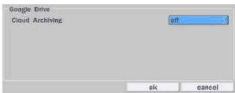
text_image
Google Drive Cloud Archiving off ok cancel1-3) Video clip will be save at Google Drive when 'Alarm-In' and 'Motion' triggered.
1-4) Set Video clip duration
text_image
Disk Event Setup Health Check select HDD Bad Sessure 10% HDD Temperature 60°C (140°F) HDD Almost Full 90% Video Clip Setup Pre Record 2 second(s) Post Record 1 second(s) Event And Notification Alarm-Out Deep e-Mail SMS select Cloud select4-3. Setup - Record Mode
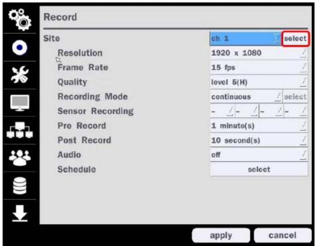
In the Setup menu, select the Record tab. Then, the Record menu is displayed as pictured below. Navigate through the menu items or change the settings using the mouse or the remote control.
text_image
Record Site ch 1 select Resolution 1920 x 1080 / Frame Rate 15 fps / Quality level 5(H) / Recording Mode continuous / select Sensor Recording - / - Pre Record 1 minute(s) / Post Record 10 second(s) / Audio off / Schedule select apply cancelFigure 4.3.1. Record Setup Screen
Table 4.3.1. Menu Items in Record Setup Screen
Menu Item Description
Site
Select a channel for applying the following settings using a mouse or a remote control. Select the "select" button beside of channel button to change the values of
| Resolution | Select 1920x1080, 1920x540, 1280x720 and 640x360 using a mouse or a remote control. |
| Frame Rate | Set the frame rate for the specified channel. The sum of the frame rate values per channel cannot exceed the maximum frame rates for a specific recording resolution. |
| Quality | Select the recording quality for the selected channel. Options are:Level 1 (Low), Level 2, Level 3, Level 4, and Level 5 (High) |
| Recording Mode | Assign the recording mode for the selected channel. Options are: Continuous, Motion, Sensor, Schedule, Disable and Smart Recording (c + m : continuous & motion, c + s : continuous & sensor)When Motion Recording is selected, Continuous + Motion recording option can be used.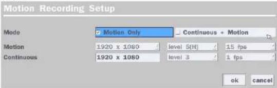 |
| Sensor Recording | Select the sensor setting for the selected channel. |
| Pre Record | Enable/disable pre-event recording. Pre-event recording time is up to 20 minutes. |
| Post Record | Set the post event recording time duration for the specified channel.(10~60 seconds) |
| Audio Enable/disable audio recording for the specified channel. | |
| Schedule Set the recording schedule. | |
4-3-1. Recording Schedules
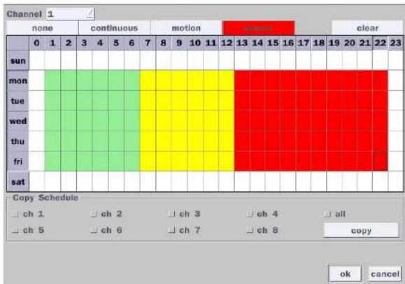
To setup a recording schedule, select Schedule in the Record menu. Navigate through the menu items or change the settings using the mouse or the remote control. Select the Channel; select one of the recording settings: None, Continuous or Motion, then highlight the area for the selected setting. To copy a schedule to a different channel, select the channel from the Copy Schedule menu, then click the Copy button.
heatmap
| Day | none | continuous | motion | clear | |---|---|---|---|---| | sun | 0 | 1 | 2 | 3 | | mon | 0 | 0 | 0 | 0 | | tue | 0 | 0 | 0 | 0 | | wed | 0 | 0 | 0 | 0 | | thu | 0 | 0 | 0 | 0 | | fri | 0 | 0 | 0 | 0 | | sat | 0 | 0 | 0 | 0 | Copy Schedule □ ch 1 □ ch 2 □ ch 3 □ ch 4 □ all □ ch 5 □ ch 6 □ ch 7 □ ch 8 copy ok cancelFigure 4.3.2. Schedule Recording Setup Screen
- none: Disable recording
• continuous: Continuous recording (Highlighted in Green)
• motion: Motion recording (Highlighted in Yellow) - sensor: Sensor recording (Highlighted in Red)
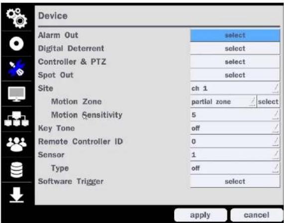
text_image
Device Alarm Out select Digital Deterrent select Controller & PTZ select Spot Out select Site ch 1 Motion Zone partial zone select Motion Sensitivity 5 / Key Tone off / Remote Controller ID 0 / Sensor 1 / Type off / Software Trigger select apply cancelFigure 4.4.1. Device Setup Screen
Table 4.4.1. Menu Items in Device Setup Screen
| Item Description | |
| Alarm Out/ Alarm Duration | Set the sensor, motion, and video loss for triggering alarm relayHDD Error and Video Loss can trigger beeping |
| Alarm-Out 1 Alarm Duration infinite Type normal open | |
Remote Controller ID Set the remote control ID.
- Select ID.
- Input the remote control ID number. (0 is all)
- An icon will indicate on the Live Screen if the remote control ID is synchronized. The options are from 0 to 99
Sensor Select the type of each sensor.
Option is Off, Normal Open or Normal Close.
Software Triger Remote trigger channels. User can set the channels that want to make a sensor recording through remotely with Software record mode.
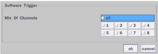
text_image
Software Trigger Mix Of Channels all 1 2 3 4 5 6 7 8 ok cancel4-4-1. Digital Deterrent
Trigger audio message via motion detection or sensor.
text_image
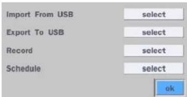
Import From USB select Export To USB select Record select Schedule select ok
text_image
Channel ch 1 From 5 16 2016 0 58 22 To 05/16/2016 00:58:32 Duration 10 second(s) File Name sound_1 start closeSchedule Schedule the sound file considering the expected situation.
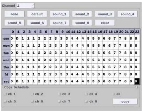
text_image
Channel 1 none default sound_1 sound_2 sound_3 sound_4 sound_5 sound_6 sound_7 sound_8 clear 0 1 2 3 4 5 6 7 8 9 10 11 12 13 14 15 16 17 18 19 20 21 22 23 sun D D 1 1 1 2 2 2 3 3 3 4 4 4 5 5 6 6 6 7 7 8 8 8 mon D D 1 1 1 2 2 2 3 3 3 4 4 4 5 5 6 6 6 7 7 8 8 8 tue D D 1 1 1 2 2 2 3 3 3 4 4 4 5 5 6 6 6 7 7 8 8 8 wed D D 1 1 1 2 2 2 3 3 3 4 4 4 5 5 6 6 6 7 7 8 8 8 thu D D 1 1 1 2 2 2 3 3 3 4 4 4 5 5 6 6 6 7 7 8 8 8 fri D D 1 1 1 2 2 2 3 3 3 4 4 4 5 5 6 6 6 7 7 8 8 sat D D 1 1 1 2 2 2 3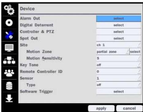
text_image
Device Alarm Out select Digital Deterrent select Controller & PTZ select Spot Out select Site ch 1 Motion Zone partial zone / select Motion Sensitivity 5 Key Tone off Remote Controller ID 0 Sensor 1 Type off Software Trigger select apply cancelFigure 4.4.4. Device Mode Setup Screen
② Open the PTZ sub menu by selecting the submenu button.
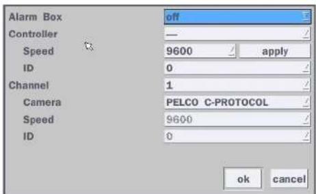
text_image
Alarm Box Controller Speed id Channel Camera Speed id off — 9600 apply 0 1 PELCO C-PROTOCOL 9600 0 ok cancel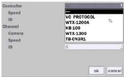
text_image
Controller Speed ID Channel Camera Speed ID VC PROTOCOL WTX-1200A KB-100 WTX-1300 TB-CN3R1 OK CancelFigure 4.4.6. Controller Selection Screen
◆Notice : DxxVX series can use UTC feature.
: UTC(Up The Coax) allows for control of the camera's OSD menu via the coax cable.
User does not need extra connection via RS-485 to control the camera's OSD menu
- How to set (Setup > Device > PTZ & Controller > PELCO C-PROTOCOL)
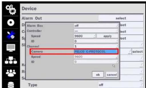
text_image
Device Alarm Out select Alarm Box off Controller — Speed 9600 apply ID 0 Channel 1 Camera PELCO C-PROTOCOL Speed 9600 ID 0 OK Cancel Type offTable 4.4.3. Menu Item in Spot-Out Setup Screen
| Item Description | |
| Spot Out Only 1 Spot Out is available to use. | |
| Spot Type Spot 1 supports only Full type. (1 channel only) | |
| Spot On Event Enable/disable channel change if an event occurs on a channel. | |
| Spot Event Set the dwell time for the display of the event activated channel. | |
| Dwell Time (3-10 sec) | |
| Sequence Enable/disable sequential display of spot channel in full screen. | |
| Sequence Dwell Set the dwell time for the spot channel display.(3-10 sec) | |
| Time | |
| Spot Channel Select a channel for spot monitoring using the mouse or the remote control and press “ok” button. |
4-4-4. Motion Zone Setup
Select Motion Zone using the mouse or the remote control and select either Partial Zone or Full Zone using the mouse control. The default value is Full Zone.
If Full Zone is selected, the motion zone grid screen is not displayed. Only set the level of sensitivity for Motion Sensitivity.
Full Zone: The motion sensor is active on the whole screen.
Partial Zone: The motion sensor is active in the set detection frame.
Select the motion detection position using the mouse or the remote control. Then left click on the mouse or left click and drag the mouse pointer to select or deselect the area. Highlighted area indicates the partial motion detection zone. Press the "ESC" button or right click on the mouse to return to the previous menu.
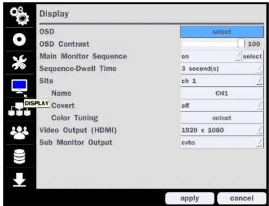
4-5. Setup - Display Mode
In the Setup menu, select the Display tab. Then, the Display menu is displayed as pictured below. Navigate through the menu items or change the settings using the mouse or the remote control. To return to the previous setup menu screen, press the "ESC" button on front panel or select the other menu tab with mouse.
text_image
Display OSD select OSD Contrast 100 Main Monitor Sequence on select Sequence-Dwell Time 3 second(s) Site ch 1 Name CH1 DISPLAY Covert off Color Tuning select Video Output (HDMI) 1920 x 1080 Sub Monitor Output cvbs apply cancelFigure 4.5.1. Display Setup Screen
Table 4.5.1. Menu Items in Display Setup Screen
Item Description
OSD
Enable/Disable displaying Channel Name/ Video Loss/ Status Bar & Icon/ Camera Type and Record Mode
| Name Set the channel name. Press the mouse button and set the channel name on the virtual keyboard. Press "Enter" key when finished its naming. The name can be made up to 36 characters. | |
| Covert Enable/disable display of the specified video channel in live display. | |
| Color Tuning Control the Brightness, Contrast, Hue and Saturation. | |
| Video Output (HDMI) | Select video output resolution(D8VX: Max. 1920 X 1080, D16VX: Max. 3840 X 2160) |
| Sub Monitor Output | Select Sub Monitor Video out through BNC port.CVBS or Spot |
4-6. Setup - Network Mode
Select the Network tab. Then, the network menu is displayed as pictured below. Navigate through the menu items or change the settings using the mouse or the remote control.
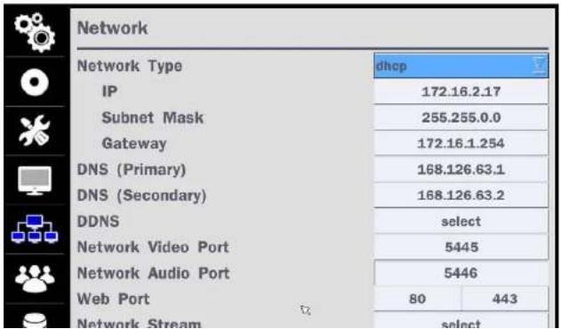
text_image
Network Network Type IP Subnet Mask Gateway DNS (Primary) DNS (Secondary) DDNS Network Video Port Network Audio Port Web Port Network Stream dhcp 172.16.2.17 255.255.0.0 172.16.1.254 168.126.63.1 168.126.63.2 select 5445 5446 80 443 selectDNS (Secondary) Enter Secondary DNS address that is assigned for the DVR
| DDNS | Dynamic Domain Name System (DDNS) allows a DNS name to be constantly synchronized with a dynamic IP address. In other words, it allows using a dynamic IP address to be associated with a static domain name so others can connect to it by the static name. Enable/disable using domain name address through DDNS server. |
Network Video Port Enter the port number, (Default: 5445)
Network Audio Port Display the network audio port (Network Port + 1).
Web Port Enter the port number for connection using web. (Default: 80)
Network Stream Set the value for network streaming.
Wireless LAN 1. Connect USB WIFI Dongle to USB connector on DVR.
-
Load the application on your smart phone or PC and enter the WIFI IP Address.
-
Find the WIFI SSID and enter the password. (Image is below.)
-
Then, the remote viewing and configuration can be used.

text_image
IP Address 192.168.50.1 SSID MY_SSID Key (8~15 Characters) 12345678 apply close* There is a distance limitation for the Wireless LAN.
Push Event Set Phone ID and check Notification function to receive an event message from DVR.

• DNS (Secondary): The secondary address of Domain Name Server

NOTE
Unless DNS is properly set, the DDNS and the e-mail features will not work.
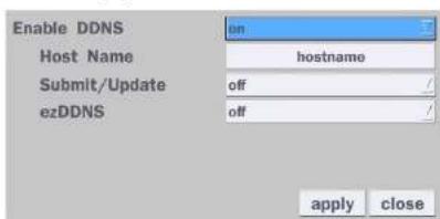
4-6-2. DDNS
DDNS (Dynamic Domain Name System) allows a DNS name to be constantly synchronized with a dynamic
IP address. It allows using a dynamic IP address to be associated with a static domain name.
Once the setting is completed, the DDNS address will be:
http://hostname.ddns.specoddns.net
For example, if you enter the host name as "D8VX", then the address will be:
http://d8VX.ddns.specoddns.net
Select Network > DDNS. The menu displays as below.
text_image
Enable DDNS Host Name Submit/Update ezDDNS on hostname off off apply closeFigure 4.6.2. Network Setup Screen - DDNS
Table 4.6.2. DDNS
| Item Description | |
| Enable DDNS | Enable/disable the Dynamic Domain Name Service. |
| Host Name | This item allows the user to setup a domain name manually. |
for commands, for remote backup, and for audio streaming. If these ports are not opened properly, you can't access the DVR beyond a router.

For live/playback streaming, for commands, for remote backup: Open the port number on Network > Network Video Port menu. The default port number is 5445.
For bi-directional audio: Open the port number on Network Audio Port. The default port number is [Network Video Port number + 1].
For web-viewer downloading and remote firmware upgrading: Open the port number on Network > Web Port menu. The default port number is 80.
4-6-4. Network Stream
User can set the Resolution, Frame Rate, and the Quality for the network stream.
- D4VX: Up to 60 fps @ 640x360, 320x 240 and 320x180 for 4 channels.
- D8VX: Up to 120 fps @ 640x360, 320x 240 and 320x180 for 8 channels.
- D16VX: Up to 240 fps @ 640x360, 320x240 and 320x180 for 16 channels.
| Net Resolution | Frame Rate | Net Quality | |
| All | 640x360 | 15 fps | level 5(H) |
| 1 | 640x360 | 15 fps | level 5(H) |
| 2 | 640x360 | level 5(H) | |
| 3 | 640x360 | level 5(H) | |
| 4 | 640x360 | level 5(H) | |
| 5 | 640x360 | level 5(H) | |
| 6 | 640x360 | level 5(H) |
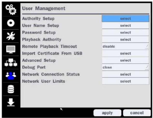
4-7. Setup - User Management Mode
In the Setup menu, select the User Management tab. Then, the User Management menu is displayed as pictured below. Navigate through the menu items or change the settings using the mouse or the remote control.
text_image
User Management Authority Setup select User Name Setup select Password Setup select Playback Authority select Remote Playback Timeout disable ✓ Import Certificate From USB select Advanced Setup select Debug Port close ✓ Network Connection Status select Network User Limits select apply cancelFigure 4.7.1. User Management Setup Screen
Table 4.7.1. Menu Items in User Management Setup Screen
Item Description
Authority
Only the Admin will have access to the menu
| Password | Setup | PB | PTZ | Rec Off | Network | |
| Password Check | # | # | # | # | # | |
| ADMIN | # | # | # | # | # | |
| USER1 | 1111 | # | # | # | # | # |
| USER2 | 1111 | # | # | # | # | # |
| USER3 | 1111 | # | # | # | # | # |
| USER4 | 1111 | # | # | # | # | # |
| USER5 | 1111 | # | # | # | # | # |
| USER6 | 1111 | # | # | # | # | # |
| USER7 | 1111 | # | # | # | # | # |
| USER8 | 1111 | # | # | # | # | # |
| USER9 | 1111 | # | # | # | # | # |
ADMIN, USER1, USER2, USER3, USER4, USER5, USER6, USER7, USER8, USER9:
Selected Checkbox: The user can access the function.
Blank Checkbox: The user can not access the function.
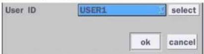
User Name Setup
Change the name of USER1, USER2, USER3, USER4, USER5, USER6, USER7, USER8, and USER9. Click "select" and change the user name on the virtual keyboard.
text_image
User ID USER1 select ok cancelPassword Setup
Options are ADMIN, USER1, USER2, USER3, USER4, USER5, USER6, USER7, USER8, and USER9:
Select User Password using the mouse or the remote control. Select "User ID" and enter the current password. And enter a new password and enter the same password again to confirm and select "ok". Then the message "Password Changed" is displayed
| Remote | Disconnect the remote playback after the specific time (Disable, 5min, 10min, 15min, 30min, 60min. |
| Playback | |
| Timeout | |
| Import | Upload https certificale through USB |
| Certificate From USB |
| Advanced | Send IP address and ports information to the control center |
| Setup | |
| Debug Port | Open or Close the ports for remote checking |
| Network | Shows the current network connection status (User, IP Address, Date/Time). |
| Connection | And do disconnect the user's network connection to click 'disconnect' button. |
Status
| Live Connections | |||
| User | IP Address | Date / Time | Action |
| ADMIN | 172.16.3.105 | 02/10/2016 22:45:05 | disconnect |
| USER1 | 172.16.3.105 | 02/10/2016 22:45:15 | disconnect |
| USER2 | 172.16.3.105 | 02/10/2016 22:45:29 | disconnect |
| USER3 | 172.16.3.105 | 02/10/2016 22:45:40 | disconnect |
| ADMIN | 172.16.3.105 | 02/10/2016 22:40:35 | disconnect |
| USER1 | 172.16.3.105 | 02/10/2016 22:46:00 | disconnect |
| USER2 | 172.16.3.105 | 02/10/2016 22:46:08 | disconnect |
| USER3 | 172.16.3.105 | 02/10/2016 22:46:22 | disconnect |
| ADMIN | 172.16.3.105 | 02/10/2016 22:41:23 | disconnect |
| USER1 | 172.16.3.105 | 02/10/2016 22:46:33 | disconnect |
| USER2 | 172.16.3.105 | 02/10/2016 22:46:40 | disconnect |
| USER3 | 172.16.3.105 | 02/10/2016 22:46:49 | disconnect |
| close | |||
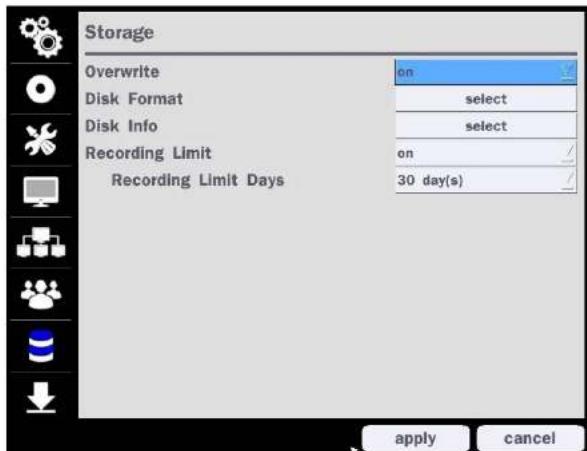
4-8. Setup - Storage Mode
In the Setup menu, select the Storage tab. Then, the Storage menu is displayed as pictured below. Navigate through the menu items or change the settings using the mouse or the remote control.
text_image
Storage Overwrite on Disk Format select Disk Info select Recording Limit on Recording Limit Days 30 day(s) apply cancelFigure 4.8.1. Storage Setup Screen
Table 4.8.1. Menu Items in Storage Setup Screen
Item Description
| Overwrite | When enabled, the DVR will continue recording and overwrite the oldest existing recorded data once the hard drive is full. When disabled, recording will stop once the hard drive is full |
Disk Info Hard drive information.
Displays the following information:
| Model Name | Temperature | Health(Good/Normal/Bad) | |
| HDD 1 | WDC WD20PURX-64P6ZY0 | 39 °C (102 °F) | Good |
| HDD 2 |
Recording Limit
Enable recording limit: The amount of data recorded in HDD will be limited to the most recent number of days as set by "Recording Limit Days".
Disable recording limit: When Overwrite is on, DVR will continue to record when HDD is full and overwrite older data. When Overwrite is off, DVR will stop recording when the HDD is full.
Recording Limit Days
Set the recording limit days. (1- 90 days) If the Recording Limit Days are set to 1, the data will be overwritten after 24 hours.
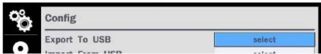
4-9. Setup - Config Mode
In the Setup menu, select the Config tab. Then, the configuration menu is displayed as pictured below. Navigate through the menu items or change the settings using the mouse or the remote control.
text_image
Config Export To USB select Import From USBTable 4.9.1. Configuration Setup
| Item Description | |
| Export To USB | User can save the current configuration (Setting values) of the DVR to the USB flash drive. Plug in the USB flash on the front panel and press the button to start the saving process. |
| Import From USB | User can upload the configuration of the DVR to another DVR using the USB Flash drive. Plug in the USB flash drive on the front panel and press the button to start the loading process. |
| Load Default | Press the button to reset the system to the default settings.The following settings such asLanguage, DVR ID, Security User Authentication, Security User P/W, Date Format, DLS settings, Network settings, HDD overwrite, Limit recording, HDD serial number, and HDD ERROR timewill not be included. |
| Load Factory Default | Press the button to reset the system to the factory default settings. |
| Software Upgrade | Upgrade software to the latest version.After connecting USB flash drive to USB port on the DVR, click SEARCH.It will automatically find the upgrade file. |
4-9-1. Software Upgrade
- In the USB flash drive root directory, create a new folder named "upgrade"
- Create sub-folder for each model under "upgrade" folder and copy each software file to their folder.
- "d4VX" for D4VX: "main_D4VX_speco_.*.*_201****"
- "d8VX" for D8VX: "main_D8VX_speco_.*.*_201****"
If selecting "Restart Now" when the USB flash drive is plugged, the following message will pop up with beep sound.
WARNING!
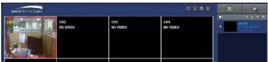
5. Live, Search and Playback
5-1. Live View
In the Live screen, video inputs from the cameras are displayed as they are configured in the Display Setup screen. When the mouse is right clicked, and the quick operation window will be displayed as below.

text_image
Search Setup Display Snapshot Super EZ Copy Enable Manual Record Instant Playback Advanced Menu EZ Setup Audio Mute Camera CTZ Enable Main Monitor Sequence Disable Alarm Out Manual Digital Deterrent Site Information System Information Export Help System Lock System Shutdown 172.16.2.16 05/13/2016 04:08:16 RC: All HDD: OverwriteFigure 5.1.1. Live Screen and Quick Operation Window
On the bottom of the screen, various On-Screen Display (OSD) symbols, which indicate the status of the DVR. are described in Table 5.1.1.
Table 5.1.1. Status Indicator Icons in Live Viewing Screen
| Icon Description | |
| Indicates the DVR is locked. Note) to unlock, right click on the live view screen and select on Unlock. | |
| Audio mute. Audio channel output can be selected from the quick operation menu | |
| Indicates that alarm is set. | |
| Indicates that alarm output is activated. | |
| Event indicator. When there is an event (motion recording, video loss, HDD fail, S.M.A.R.T), this icon will be highlighted. | |
| Indicates that a network client is connected to the DVR. | |
| Indicates that sequencing mode is enabled. | |
| 2009/04/14 17:23:40 | Displays the current date and time. |
| RC: ALL Remote control ID display. If a remote ID is not set, the message "ALL" is displayed. | |
| When Overwrite is not enabled, this displays the percent of the hard dis usage from 0-99%. When Overwrite is enabled, the Bar will indicate with Overwrite | |
| Continuous recording in progress. | |
| Manual recording in progress. To set the Manual recording mode, press the | |
| Super EZ Copy Direct Backup of the selected channel to USB flash drive without going through the search mode. | |
| Enable Manual Record | Manual Record button. Click this button to enable manual recording. Also known as Panic Record. |
Advanced Menu
| EZ Setup Select this option to start EZ Setup Wizard | |
| Audio | Select this option to set an audio channel to output; (Channel 1 through 4, Audio Mute). |
| Camera PTZ Select this option and the PTZ user interface will appear. | |
| Enabel Main Monitor Sequence | Select this option to enable/disable sequence function. |
| Disable Alarm Out | Click this button to enable/disable Alarm outputs |
| Manual Digital Deterrent | Window where users can manually trigger the digital deterrent audio "Right now it just says "use". |
| Manual Digital Deterrent Select Digital Deterrent Source Source Name Default ok close | |
| Site Information | Press the button to view the record setting of a selected channel. |
| System Information | Press the button to view the system information. |
| Model Name D16VX Software Version Ver 5.3.1N_20161209 Storage Size 3645 GB | |
5-1-1. PTZ Control
Table 5.1.3. Menu Items in PTZ Control Window
| Image Item Description | ||
| INITIALIZE Initialize the PTZ settings of the selected camera | ||
| PAN/TILT | Select PAN/TILT using the ▲▼◀ and ▶button, then press SEL. Adjust the tilt (UP/DOWN)/pan (LEFT/RIGHT) position using the ▲▼◀and ▶buttons. | |
| ZOOM/FOCUS | Select ZOM/FOCUS using the▲▼◀ and ▶buttons, then press SEL. Adjust the zoom (UP/DOWN)/ focus (LEFT/RIGHT)position using the ▲▼◀ and ▶ buttons. | |
| OSD | Select OSD to enter the menu. Control keys are Right, Left, UP, Down, Select, Far (REW KEY), and Near (FF KEY). Press the ESC button to return to the previous menu. Press the PTZ button to close the OSD menu. | |
| AUTOSCAN | Press the right key(▶) to start auto scan. Press the left key (◀) to stop auto scan. | |
| PRESET | Select PRESET, then press the left key(◀). A number input window will appear. Set the number (3digits) using the number key, then press the SEL to confirm the preset number for the current | |
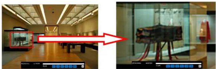
5-2. Digital Zoom in Live and Playback Screen
VX series supports Digital Zoom feature during live and playback mode.
- Double click the target channel.

text_image
CH 2 CH5 CH 6- Click the left button of the mouse and drag to make rectangular shape.
natural_image
Two-panel image showing a museum interior with a red arrow pointing to a display case containing an artifact; no visible text or symbols.5-3. Search Screen
To enter the search screen menu, select Search menu on the screen using the mouse or press Search icon on live screen.
5-3-1. EZSearch
The EZSearch window is used to find stored video with ease using the thumb nail playback screen.
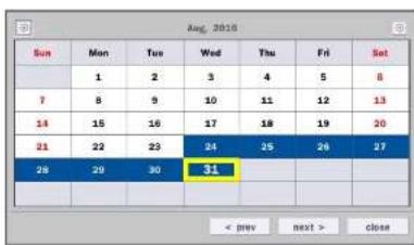
text_image
Sun Mon Tue Wed Thu Fri Sat 1 2 3 4 5 6 7 8 9 10 11 12 13 14 15 16 17 18 19 20 21 22 23 24 25 26 27 28 29 30 31 < next > closeFigure 5.3.2. Calendar Screen
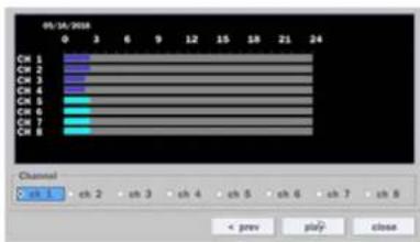
text_image
05/16/2018 0 3 6 9 12 15 18 21 24 CK 1 CK 2 CK 3 CK 4 CK 5 CK 6 CK 7 CK 8 Channel 0 sh 1 sh 2 sh 3 sh 4 sh 5 sh 6 sh 7 sh 8 < prev play> closeFigure 5.3.3. Channel Selection Screen
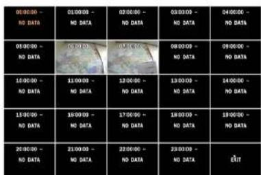
text_image
08:00:00 - NO DATA 08:30:00 - NO DATA 15:00:00 - NO DATA 15:30:00 - NO DATA 20:00:00 - NO DATA 08:00:00 - NO DATA 08:30:00 - NO DATA 15:00:00 - NO DATA 15:30:00 - NO DATA 20:00:00 - NO DATA 08:30:00 - NO DATA 15:30:00 - NO DATA 21:00:00 - NO DATA 15:30:00 - NO DATA 21:30:00 - NO DATA 21:30:00 - NO DATA EXITStep1. 24 Hourly Thumbnail Screen
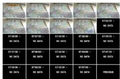
text_image
07:30-07 07:31-07 07:32-07 07:33-07 07:34-07 07:35-07 07:36-07 07:37-07 07:38-07 07:39-07 07:40-07 07:41-07 07:42-07 07:43-07 07:44-07 07:45-07 07:46-07 07:47-07 PREVIOUSStep2. Every 2 minutes and 30 seconds

text_image
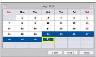
CH2 NO DATA5-3-2. Smart Search
Smart Search is search the selected area quickly. User can search need to know area.
text_image
Sun 1 2 3 4 5 6 7 8 9 10 11 12 13 14 15 16 17 18 19 20 21 22 23 24 25 26 27 28 29 30 31 < prev next > closeFigure 5.3.4. Calendar Screen

text_image
06/16/2008 Channel ch 1 ch 2 ch 3 ch 4 ch 5 ch 6 ch 7 ch 8 prev play closeFigure 5.3.5. Channel Selection Screen
text_image
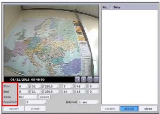
08/31/2016 09:48:00 Start 8 31 2016 9 48 0 End 8 31 2016 14 16 0 Zone full select Sensitivity 5 Interval 1 sec report e-mail No. Date restart search close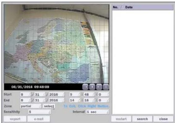
text_image
08/31/2016 09:48:00 Start 8 / 31 / 2016 9 / 48 / 0 End 8 / 31 / 2016 14 / 16 / 0 Zone partial select To Exit, Close Right Outline. Sensitivity 5 Interval 1 sec export e-mail No. Date restart search close4) Click "select" button after selection as 'Partial' then user can drag the area.
5) Click right mouse button when the area selection was finished.
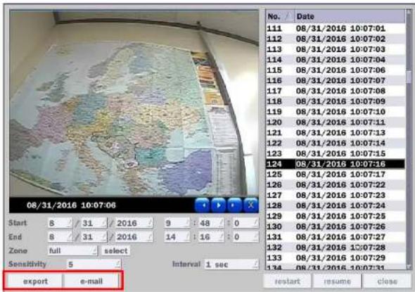
6) Select 'search' then show the detected motion lists at the right blank.

text_image
Wall-mounted world map with country labels and a small inset image showing regional data and text.| No. | Date |
| 111 | 08/31/2016 10:07:01 |
| 112 | 08/31/2016 10:07:02 |
| 113 | 08/31/2016 10:07:03 |
| 114 | 08/31/2016 10:07:04 |
| 115 | 08/31/2016 10:07:06 |
| 116 | 08/31/2016 10:07:07 |
| 117 | 08/31/2016 10:07:08 |
| 118 | 08/31/2016 10:07:09 |
| 119 | 08/31/2016 10:07:10 |
| 120 | 08/31/2016 10:07:11 |
| 121 | 08/31/2016 10:07:13 |
text_image
08/31/2016 10:07:06 Start 8 / 31 / 2016 9 : 48 : 0 / End 8 / 31 / 2016 14 : 16 : 0 / Zone full select Sensitivity 5 Interval 1 sec export e-mail No. Date 111 08/31/2016 10:07:01 112 08/31/2016 10:07:02 113 08/31/2016 10:07:03 114 08/31/2016 10:07:04 115 08/31/2016 10:07:06 116 08/31/2016 10:07:07 117 08/31/2016 10:07:08 118 08/31/2016 10:07:09 119 08/31/2016 10:07:10 120 08/31/2016 10:07:11 121 08/31/2016 10:07:13 122 08/31/2016 10:07:14 123 08/31/2016 10:07:15 124 08/31/2016 10:07:16 125 08/31/2016 10:07:17 126 08/31/2016 10:07:22 127 08/31/2016 10:07:23 128 08/31/2016 10:07:24 129 08/31/2016 10:07:25 130 08/31/2016 10:07:26 131 08/31/2016 10:07:27 132 08/31/2016 12:07:28 133 08/31/2016 10:07:29 134 08/31/2016 10:07:31 restart resume close8) 'export' and 'e-mail' icon will be activate for backup or mail notice
5-3-3. Time Line Search
The Calendar Search window is used to find the stored video by using the time line bar.

text_image
Sun 1 2 3 4 5 6 7 8 9 10 11 12 13 14 15 16 17 18 19 20 21 22 23 24 25 26 27 28 29 30 31
text_image
08/31/2018 00:00:00 24 CH 1 CH 2 CH 3 CH 4 Channel sh ch 1 sh 2 sh 3 sh 4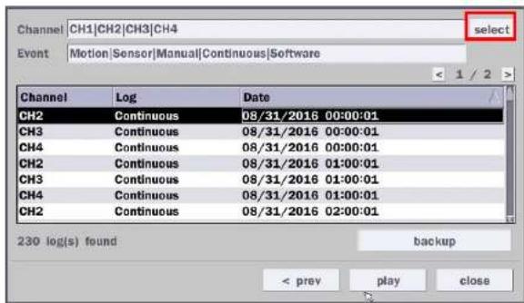
text_image
Channel |CH1|CH2|CH3|CH4 Event |Motion|Sensor|Manual|Continuous|Software select < 1 / 2 > Channel Log Data CH2 Continuous 08/31/2016 00:00:01 CH3 Continuous 08/31/2016 00:00:01 CH4 Continuous 08/31/2016 00:00:01 CH2 Continuous 08/31/2016 01:00:01 CH3 Continuous 08/31/2016 01:00:01 CH4 Continuous 08/31/2016 01:00:01 CH2 Continuous 08/31/2016 02:00:01 230 log(s) found backup < prev play closeFigure 5.3.9. Event Search Screen
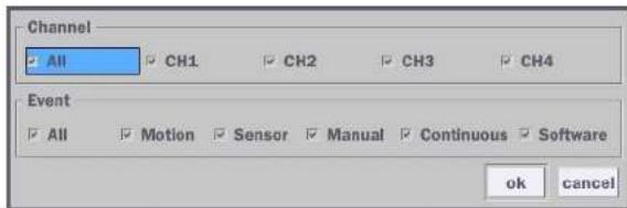
When the Event menu is selected, a calendar is displayed that highlights dates with recorded event data. Select a specific date and the event log will be displayed. After selecting the event, Press the "play" button to playback the recorded data or press the "backup" button to export the data. User can find a data of the specific channel and event using a button in the above red box as following Figure 5.3.9. Press the "prev" to return to the Search window.
text_image
Channel All CH1 CH2 CH3 CH4 Event All Motion Sensor Manual Continuous Software ok cancel5-3-8. Archive List
The ARCHIVE Search window is used to find previously stored video or images.
text_image
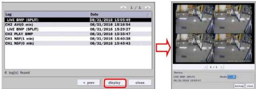
Log Date LIVE BMP (SPLIT) 08/31/2016 15:05:49 CH2 AVI(0 min) 08/31/2016 15:16:54 LIVE BMP (SPLIT) 08/31/2016 15:29:27 CH2 PLAY BMP 08/31/2016 15:35:47 CH1 NSF(1 min) 08/31/2016 15:40:38 CH1 NSF(0 min) 08/31/2016 15:45:43 6 log(s) found < prev display close Backup LIVE BMP (SPLIT) Media Loss 08/31/2016 15:05:47 backup closeFigure 5.3.11. Archive Search Screen
When the Archive menu is selected, the user can see a calendar, which has archive data. Select a specific date and then the archived data will be displayed. Press the Display button to view the still image or the first frame of the selected video, then the user can export the selected data.
5-3-9. Log List
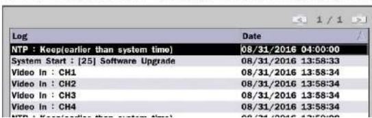
You can access the LOG list search screen by selecting LOG on the SEARCH window.
text_image
Log Date NTP : Keep(earlier than system time) 08/31/2016 04:00:00 System Start : [25] Software Upgrade 08/31/2016 13:58:33 Video In : CH1 08/31/2016 13:58:34 Video In : CH2 08/31/2016 13:58:34 Video In : CH3 08/31/2016 13:58:34 Video In : CH4 08/31/2016 13:58:34 NTP : Keep(earlier than system time) 08/31/2016 13:58:00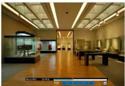
natural_image
Interior view of a museum gallery with wooden flooring, display cases, and ceiling lighting (no visible text or signage)Figure 5.4.1. Play Mode Screen
The following status bar hides automatically and appears again if a mouse pointer is positioned to the bottom of the screen.
Table 5.4.1. Button Functions in PLAY Mode
| Button Description | |
| 1x, 2x, 4x, 8x,16x, 32x for D4VX1x, 2x, 4x, 8x,16x for D8VX1x, 2x, 4x, 8x for D16VXSingle Channel backward playback speed 1x, 2x, 4x, 8x, 16x, 32x, 64x | |
| Jump/Step backward. The playback position moves 60 seconds backward. | |
| Press to play or pause recorded video. | |
| Jump/Step forward. Playback position moves 60 seconds forward. | |
6. Export and Back Up
6-1. Still Image Backup onto USB Flash Drive
Still images can be captured and archived onto a USB flash drive or an USB external hard drive in live mode or while playing back recorded video.
- Select a specific channel, which wants to backup on live screen.
- When you press "Snapshot" button on Quick operation window, the media selection window screen will display.
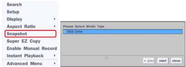
text_image
Search Setup Display Aspect Ratio Snapshot Super EZ Copy Enable Manual Record Instant Playback Advanced Menu Please Select Media Type USB Drive < prev start close- Once you press "start" button, the system will capture a still image and archive onto a USB flash drive.

NOTICE
USB Flash Drive must be in FAT32 file format.
6-2. Video Backup onto USB Flash Drive during playback
Video can be captured and archived onto the USB flash drive or a hard drive while playing back the
recorded video. In playback mode, press the
"Export" button to launch the backup function.
-
When you press "Export" button on the selected channel or all channels, the DVR will ask whether to archive a Still Image, NSF, AVI or EXE and select the proper media type.
-
Select USB Drive (Flash Drive) to back up less than an hour. Select USB HDD (Large Backup) to back up from 1 hour to 24 hours. (Only for NSF type)
-
Once you select the channel and duration, the system will start to archive the data to the USB drive.
-
The following shows the image to complete the backup. Select lose to return to the previous screen.
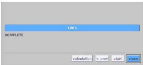
text_image
100% COMPLETE calculation < prev start close6-3. EZCopy: Video Backup onto USB Flash Drive during playback
Using EZCopy feature, Video can be easily archived onto the USB flash drive or a hard drive.
In playback mode, press the "Copy" button to launch the backup function.
- Press "EZCopy" button on the selected channel or all channels.

text_image
1/4 EZ- Then, EZCopy START time will display.

text_image
2014/03/04 03:33- EZCopy window will display. The DVR will ask whether to archive a NSF, AVI or EXE.
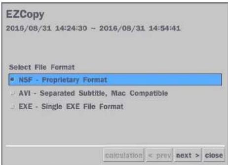
text_image
EZCopy 2016/08/31 14:24:30 - 2016/08/31 14:54:41 Select File Format • NSF - Proprietary Format □ AVI - Separated Subtitle, Mac Compatible □ EXE - Single EXE File Format calculation < prev next > close- After backup format is selected, also select media type and channel(s) to archive the data to the media.
6-4. Transferring Still Images or Video from the ARCHIVE List
The stored data in the hard drive can be found in the ARCHIVE list in the SEARCH window.
User can back up still images or video into the storage device from the ARCHIVE list.
- Select the date to begin searching and navigate through the days using the mouse or the remote control.
- Once you have selected the date, press the NEXT button to open the list of stored data.
- Use the mouse or the remote control to scroll through the archive list.
- Select a list of stored events in the archive list.
- Once the desired event has been selected, press the DISPLAY button to view the still image or the first frame of the selected video.
6-5. Playback of Backup Video
6-5-1. AVI Format
AVI format: AVI format video can be played back by Window Media Player™ or other media player that is compatible with AVI format video.
- Please install the Decoder Filter that the DVR copies "DvrPlayer" folder on USB flash drive with the video. Decoder Filter is exported to the "/DvrPlayer" folder of the USB drive.
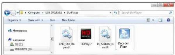
text_image
Computer + USB DRIVE (E:) - DnVPlayer Organize Share with Run New Folder HomeGroup Computer OS (C:) USB DRIVE (E:) CNC_Ctrl_Play y.dll HDPlayer R:\26\docw mull Deconer Filter- Otherwise, the video and time stamp over video can't be properly played back and wont be displayed on Window Media Player™.

natural_image
Interior view of a museum or exhibition hall with wooden flooring, display cases, and ceiling lighting (no visible text or signage)
Timestamp On AVI. The subtitle is embedded to the video clip file.
subtitle is embedded to the AVI file. To display a subtitle, user should install a special filter called "Decoder Filter".
6-5-2. NSF Format
7. Network Access Using the Multi-Sites Network Viewer
7-1. Overview
The SpecoTech Multi Client is a multiple site monitoring client software with; video, audio, and alarm signals from the DVRs over the network. The SpecoTech Multi Client does not limit the number of DVR units to register.
The program displays up to 16 DVRs and supports dual monitors.
On the program, user may control PTZ cameras on the DVRs. By attaching a microphone and speaker system to devices on site, the user may make bi-directional audio communication over the network.
7-2. PC Requirements
Minimum PC Requirements
| CPU Intel Core | 3 |
| 1.8Ghz | |
| Memory 2GB DDR2 | |
| VGA 512MB | |
| Resolution | 1280x720 |
| Disk Space | 1GB |
| OS | Windows 2000, XP Professional, XP Home, Vista, 7 (NOTE: Not all versions of Vista and 7 are supported) |
| Network 10/100Base T | |
| Others | Direct X 9.0c or Higher |
Recommended PC Requirements
| CPU Intel Core i5 |
| 2Ghz or higher. |
7-3. Installation of the Program
- Insert the provided CD in the CD drive and double-click "SpecoTech Multi Client (XXXX).exe"
- Select a destination folder and click "Next".
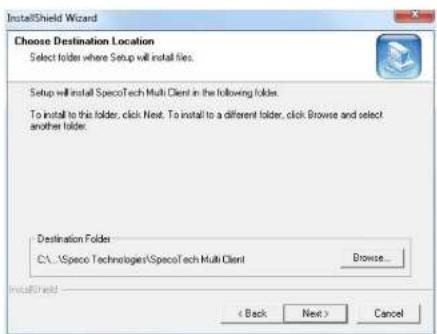
text_image
InstallShield Wizard Choose Destination Location Select folders where Setup will install files. Setup will install SpecoTech Multi Client in the following folders. To install to this folder, click Next. To install to a different folder, click Browse and select another folder. Destination Folders C:\...\Speco Technologies\SpecoTech Multi Client Browse... < Back Next > Cancel- Select the program folder and click "Next".
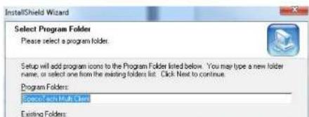
text_image
InstallShield Wizard Select Program Folder Please select a program folder. Setup will add program icons to the Program Folder listed below. You may type a new folder name, or select one from the existing folders list. Click Next to continue. Program Folders: Green with Math Card Existing Folders:7-4. Live Window
When installation is completed, double click the "SpecoTech Multi Client" icon on your desktop to start the program.
7-4-1. Main User Interface
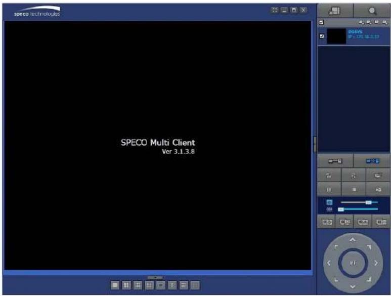
text_image
SPECO Multi Client Ver 3.1.3.87-4-2. Control Buttons
| Button Description | ||
 | LOCAL PLAYBACK | Click this icon to run a playback window to search and play videos that are recorded in the local PC. |
 | REMOTE PLAYBACK | Click this icon to run a playback window to search and play videos that are recorded in the remote DVR. |
 SITE MANAGEMENT SITE MANAGEMENT | THUMBNAIL REFRESH: Click this icon to refresh and renew thumbnail image of the connected sites.SITE ADDITION: Click this icon to open 'Site Addition' window.SITE DELETE: Click this icon to delete site from the index window, after disconnect a site.NET FINDER: Select the site from the index window and click this icon to modify the information of specific site. | |
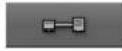 | CONNECT | Click this icon to connect the selected site/sites. |
| [AACS] | DISCONNECT | Click this icon to disconnect the selected site/sites. |
 | SETUP | Click this icon to setup configuration of SpecoTech Multi Client. |
 | CAPTURE | Click this icon to capture a still image. |
 | EVENT LIST | Opens list of events logged by the SpecoTech Multi Client. |
 | PAUSE | Click this icon to play/pause live video. |
7-5. Search and Playback Window
7-5-1. Main User Interface
You can access to search window by clicking the search icon (Local Playback / Remote Playback) on the upper right of the Live Window.
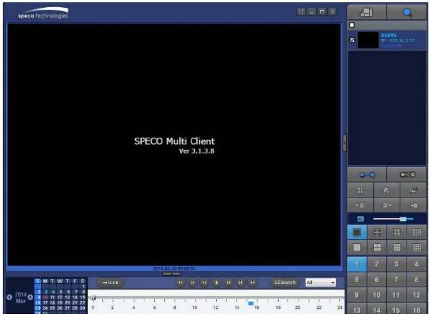
text_image
speco technologies SPECO Multi Client Var 3.1.3.8 2014.05.16:09:30:00 M T W T F S 2 3 4 5 6 7 8 B 11 12 13 14 15 B 17 18 19 20 21 22 B 24 25 26 27 28 29 0 2 4 6 8 10 12 14 16 18 20 22 24 E:\Search AI 2014 Mar7-5-2. Main Control Panel
| Button Description | |
 LOCAL PLAYBACK LOCAL PLAYBACK | Click this icon to run a playback window to search and play videos that are recorded in the local PC. |
 REMOTE PLAYBACK REMOTE PLAYBACK | Click this icon to run a playback window to search and play videos that are recorded in the remote DVR. |
 | Display the site information and the connection status. |
 CONNECT CONNECT | Click this icon to connect the selected site/sites. |
 DISCONNECT DISCONNECT | Click this icon to disconnect the selected site/sites. |
 ETUP ETUP | Click this icon to setup configuration of SpecoTech Multi Client. |
 CAPTURE CAPTURE | Click this icon to capture a still image. |
 /ENT LIST /ENT LIST | Opens list of events logged by the SpecoTech Multi Client. |
 Copy Start Copy Start | Click this icon to set the beginning time for backup of the recorde video in AVI format. |
 Copy End Copy End | Click this icon to set the ending time for backup of the recorded video in AVI format. |
 | Click this icon to backup the recorded video in AVI format. |
  | To change a timeline scale from 24 hours to 60 minutes.The timeline shows recorded data in color on the bar. You can adjust the timeline scale and move it to the time you wish to playback. Then click the play icon to display the recorded video. |
  | Playback buttons. |
| EZSEARCH: Thumbnail search over the network.- Shows 24 thumbnail images, one for each hour from 00:00 to 23:00.- Each hour is further broken up 24 segments; each is 150sec.- Then select the tile to play* Click the “PREVIOUS” button to go the previous step. | |
 | Digital Zoom Window in Live and Playback. (Only available in Single Channel Viewing) |
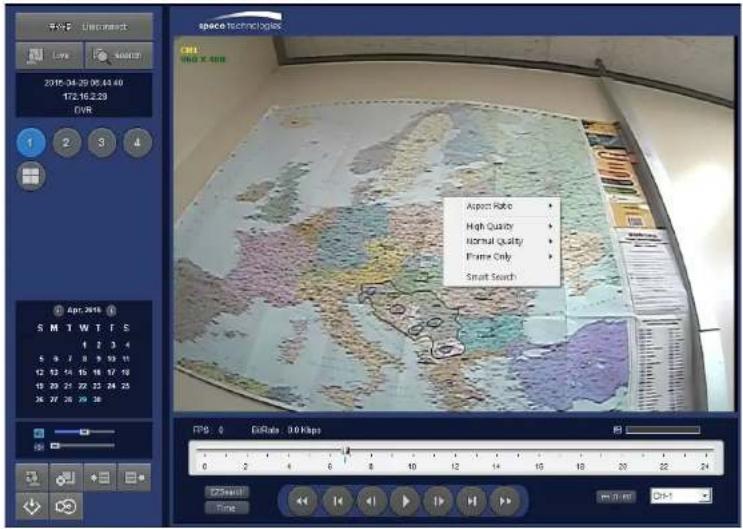
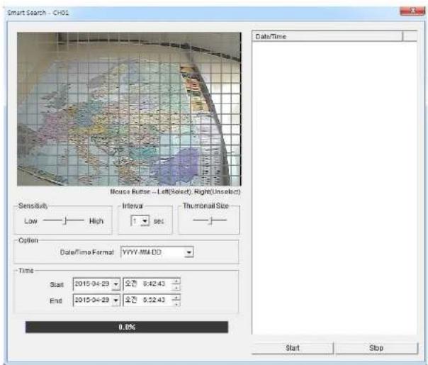
7-5-3. SMART SEARCH
1) User can search with selected area
2) Click right mouse button when playback
text_image
space technologies CRE1 WBO X 408 2015-24-29 00:43:40 172.16.2.23 FVR 1 2 3 4 Apr. 2016 S M T W T F S 1 2 3 4 5 9 7 8 9 10 11 12 13 14 15 16 17 18 19 20 21 22 23 24 25 36 37 38 39 40 Aspect Ratio High Quality Normal Quality Frame Only Smart Search FPS: 0 FullRate: 3.0 kbps 0 2 4 6 8 10 12 14 16 18 20 22 24 C:\Users\Time| Aspect Ratio | ▶ |
| High Quality | ▶ |
| Normal Quality | ▶ |
text_image
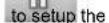
Smart Search - CHOS Mouse Rutter -- Left(Select), Right(Unselect) Sensitivity Low —— High Interval 1 set Thumbnail Size Option Date/Time Format: YYYY-MM-DD Time Start 2015-04-23 9:30 6:42.43 End 2015-04-23 9:30 6:42.43 0.0% Start Stop
text_image
Smart Search - CH02 Date/Time 2015-04-29 05:33:42 2015-04-29 05:53:43 2015-04-29 05:56:01 2015-04-29 05:58:02Setup of SpecoTech Multi Client
Click the setup icon

window is displayed as below.
configuration of SpecoTech Multi Client software. The SETUP
7-6-1. General
Security Option: Set a password for security options. Select security options and set a password.
Then when you access any of selected functions, you need to enter the password.
You can also set the save path for capturing and backup.
Save Path: Specify the location to save captured still image for Capture and Backup data.
Miscellaneous
Automatic Reconnection: If enabled, the software will automatically try to reconnect to the last successful IP address. But, when CLIENT ACCESS is OFF on the DVR, the software will not try to reconnect even if it is enabled.
Always On Top: If enabled, the software display will be continuously on the top of other windows.
Time Format: Change the way the Client software displays the time.
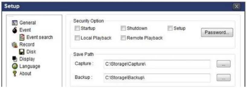
text_image
Setup General Event Event search Record Disk Display Language About Security Option Startup Shutdown Setup Local Playback Remote Playback Password... Save Path Capture : C:\Storage\Capture\ Backup : C:\Storage\Backup\7-6-2. Event
Event log can be archived and searched.
Event Log: Specify the location to save event logs and select event to archive.
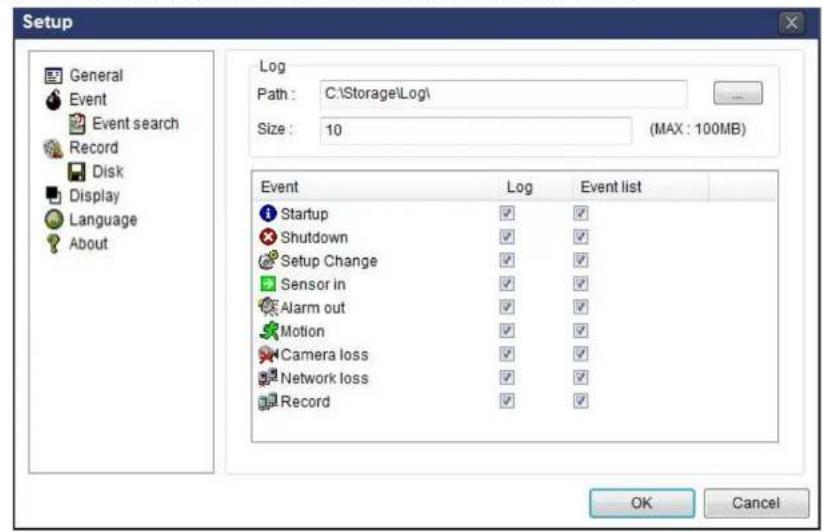
text_image
Setup General Event Event search Record Disk Display Language About Log Path : C:\Storage\Log\ Size : 10 (MAX : 100MB) Event Log Event list Startup ✓ ✓ Shutdown ✓ ✓ Setup Change ✓ ✓ Sensor in ✓ ✓ Alarm out ✓ ✓ Motion ✓ ✓ Camera loss ✓ ✓ Network loss ✓ ✓ Record ✓ ✓ OK CancelEvent Search: Event log can be searched from the selected time.
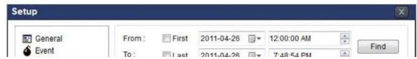
text_image
Setup General Event From: First 2011-04-26 12:00:00 AM To: Last 2011-04-26 7:48:54 PM Find7-6-3. Record
Record Setup: You can set the recording conditions as the following; Always, Event, or Auto record. And you can also select target DVR/DVRs and channel/channels. When you set the recording condition to event, you can set event for motion or alarm with duration.

text_image
Setup General Event Event search Record Disk Display Language About Record Condition Always Event Auto record Event Motion Alarm Duration: 5 Sec Channel Site Site 1 All site All NO. CH 1 Channel 1 2 Channel 2 3 Channel 3 4 Channel 4 5 Channel 5 6 Channel 6 OK CancelRecord Local Storage Setup: You can select the local disk to record and the amount of disk space you want to allow the program to use for recording. You can also select the option to overwrite data or stop recording when the maximum amount of disk space is full.

text_image
Setup7-6-4. Display
You can select the OSD (On Screen Display) to be displayed.
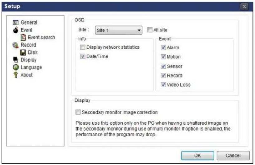
text_image
Setup General Event Event search Record Disk Display Language About OSD Site : Site 1 All site Info Display network statistics Date/Time Event ✓ Alarm ✓ Motion ✓ Sensor ✓ Record ✓ Video Loss Display Secondary monitor image correction Please use this option only on the PC when having a shattered image on the secondary monitor during use of multi monitor. If option is enabled, the performance of the program may drop. OK Cancel7-6-5. Language
English, French and Spanish is selectable.
text_image
Setup General7-6-6. About
"About" provides network client version information.
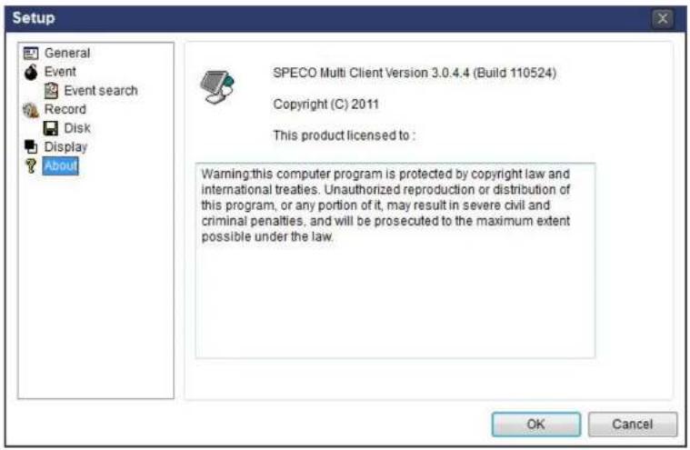
text_image
Setup General Event Event search Record Disk Display About SPECO Multi Client Version 3.0.4.4 (Build 110524) Copyright (C) 2011 This product licensed to : Warning this computer program is protected by copyright law and international treaties. Unauthorized reproduction or distribution of this program, or any portion of it, may result in severe civil and criminal penalties, and will be prosecuted to the maximum extent possible under the law. OK Cancel7-7. Remote Setup
The menu settings for the DVR unit can be set over network.
Put the cursor of the mouse on the channel, which is connected to the site and right click on the mouse to open the submenu. Then the following window is displayed as below. Select the REMOTE SETUP.
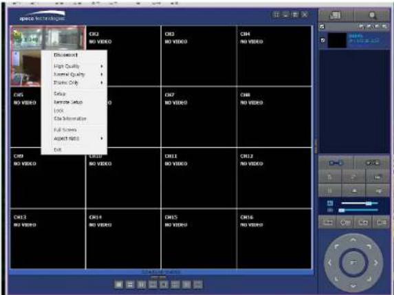
text_image
space information Ch32 NO VIDEO Ch33 NO VIDEO Ch4 NO VIDEO Ch41 NO VIDEO Ch42 NO VIDEO Ch43 NO VIDEO Ch44 NO VIDEO Ch45 NO VIDEO Ch46 NO VIDEO Ch47 NO VIDEO Ch48 NO VIDEO Ch49 NO VIDEO Ch50 NO VIDEO Ch51 NO VIDEO Ch52 NO VIDEO Ch53 NO VIDEO Ch54 NO VIDEO Ch55 NO VIDEO Ch56 NO VIDEOThen the setup window is displayed. The specified menu screen is displayed on the upper left of the screen.
Enter the password of the DVR when prompted. (NOTE: The password is same with DVR setup password.)
Setting is the same as with the DVR menu setting. Refer to the corresponding pages for details on the setting items.

7-7-1. System
Select System to set system and time settings.
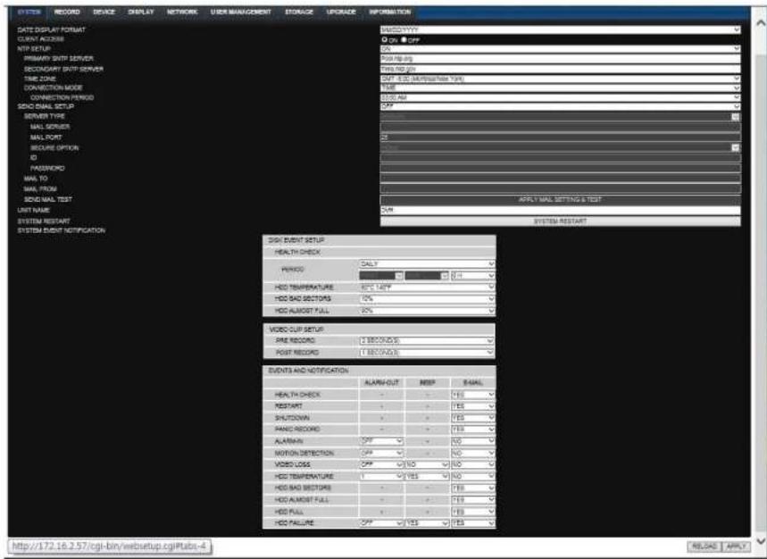
text_image
SYSTEM RECORD DEVICE DISPLAY NETWORK USER MANAGEMENT STORAGE UPGAGE INFORMATION DATE DISPLAY FORMAT CLIENT ACCESS NTP SETUP PRIMARY SNTP SERVER SECTIONARY SNTP SERVER TIME ORDER CONNECTION MODE CONNECTION PERIOD SDDI MAIL SETUP SERVER TYPE MAIL SERVER MAIL PORT SECURE OPTION ID PASSWORD MAIL TO MAIL FROM SDDI MAIL TEST UNIT NAME SYSTEM RESTART SYSTEM RESET NOTIFICATION RISK Event Setup HEALTH CHECK PERIOD DAILY HDD TEMPERATURE 80% LOW HDD BAD SECTIONS 10% HDD ALMOST FILL 20% VIDEO CUP SETUP PRE RECORD 2 RECORDS POST RECORD 1 RECORDS EVENTS AND NOTIFICATION ALARMOUT RESP E-MAIL HEALTH CHECK - - - - YES RESTART - - - YES SHUTDOWN - - - YES PAND RECORD - - - YES ALMAN OFF - - - NO MOTOR DETECTION OFF - - - NO VIDEO LOSS OFF - - NO HDD TEMPERATURE - - - YES HDD BAD SECTIONS - - - - YES HDD ALMOST FILL - - - - YES HDD FILL - - - - YES HDD FAILURE OFF - - YES YES APPLY MAIL SETTING & TEST COM SYSTEM RETART http://172.16.2.57/cgi-bin/websetup.cgi?abs-4• DATE DISPLAY FORMAT: Select the date display format.
- CLIENT ACCESS: Enable/Disable remote access through network client software.
o SEND MAIL TEST: Examine the function with registered information.
- USER NAME: Name the DVR
- SYSTEM RESTART
- SYSTEM EVENT NOTIFICATION
Allows the user to set EVENT NOFICIATION ON or OFF
- HEALTH CHECK
(Allows the user to set MAIL STATUS periodically): DAILY or WEELY or MONTHLY
- HDD TEMPERATURE
- HDD BAD SECTOR
○ HDD ALMOST FULL
o VIDEO CLIP SETUP: Setting the duration for pre and post recording. - EVENTS AND NOTIFICATION
- HEALTH CHECK / RESTART / SHUTDOWN / PANIC RECORD
Enable Email Notification in the event a problem occurs with the VX.
- ALARM-IN : Enable Email Notification when the camera detects sensor
- MOTION DETECTION : Enable Email Notification when the camera detects motion
o VIDEO LOSS: Enable Email, Beep and Alarm output Notification when the camera signal is lost.
o HDD TEMPERATURE : Enable Email Beep and Alarm output Notification when the HDD reaches the maximum temperature
○ HDD BAD SECTOR: Enable Email Notification when the HDD has bad sectors. - HDD ALMOST FULL: Enable Email Notification when the HDD is almost full.
o HDD FULL: Enable Email Notification when the HDD is full.
o HDD FAILURE: Enable Email, Beep and Alarm output Notification when the HDD fails.
7-7-2. Record
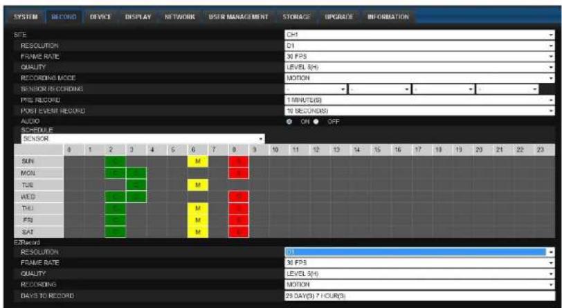
Select RECORD tab to set the recording conditions.
text_image
SYSTEM RECORD DEVICE DISPLAY NETWORK USER MANAGEMENT STORAGE UPGRADE INFORMATION SITE CH1 RESOLUTION Q1 FRAME RATE 30 FPS QUALITY LEVEL 5(H) RECORDING MODE MOTION SENSOR RECORDING FIRE RECORD 1 MINUTE(S) POST EVENT RECORD 70 RECONDS AUDIO ON OFF SCHEDULE SENSOR 8 1 2 3 4 5 6 7 8 9 10 11 12 13 14 15 16 17 18 19 20 21 22 23 SUN MON TUE AED THU FRJ SAT EXPRESS RESOLUTION 30 FPS FRAME RATE 30 FPS QUALITY LEVEL 5(H) RECORDING MOTION BAYE TO RECORD 23 DAY(S) 7 HOUR(S)These settings apply to the specified channel only.
- Recording Setup
o RESOLUTION: Sets the resolution for the recordings. The value applies to an individual channel.
o FRAME RATE: Sets the recording rate.
o QUALITY: Sets the image quality in 5 levels.
o RECORDING: Sets the recording mode.
o RECORDING MODE: CONTINUOUS. SCHEDULE. MOTION. SENSOR
7-7-3. Device
Select Device to set Spot Out, Enable/Disable CVBS Out, motion zone.
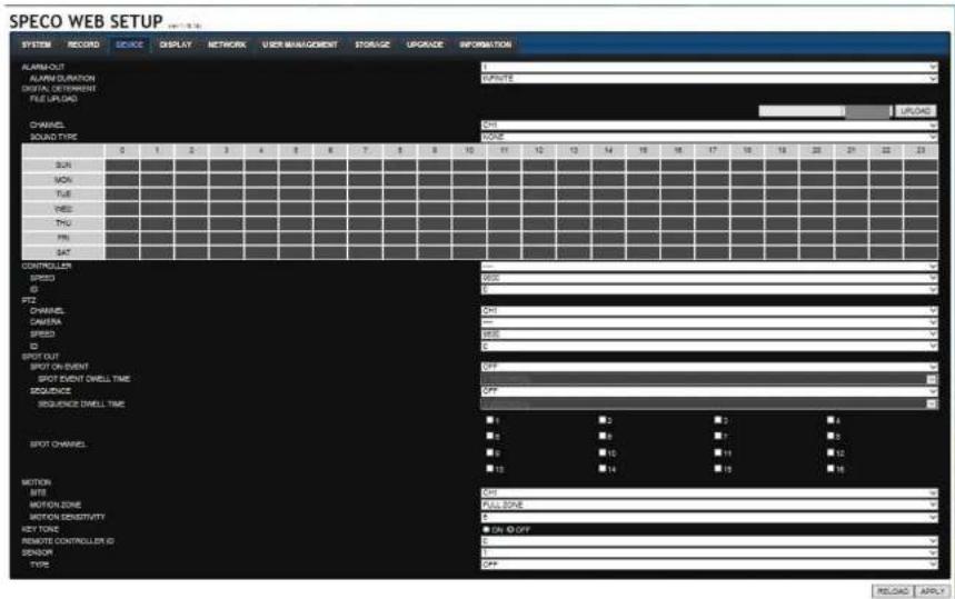
text_image
SPECO WEB SETUP SYSTEM RECORD SERVICE DISPLAY NETWORK USER MANAGEMENT STORAGE UPGRADE INFORMATION ALARM OUT ALARM DURATION DIGITAL DIFFERENCE FILE UPGARD CHANNEL SOUND TYPE 0 1 2 3 4 5 6 7 8 9 10 11 12 13 14 15 16 17 18 19 20 21 22 23 SUN MON TUE YES THU PN SAT CONTROLLER SPICE ID PTZ CHANNEL CAMERA SPRING ID SPOT OUT SPOT ON SOUT SPOT EVENT DWELL TIME SEQUENCE SEQUENCE DWELL TIME SPOT CHANNEL MOTION SITE MOTION ZONE MOTION SENSITIVITY KEY TONE REMOTE CONTROLLER ID SENSOR TYPE INFINITE ON/OFF OFF RELOAD APPLY GNDS GNDS CHD CHD OFF OFF F1 F2 F3 F4 F5 F6 F7 F8 F9 F10 F11 F12 F13 F14 F15 F16 FULL ZONE ON ID OFF OFF• ALARM OUT: Set the alarm out duration.
- DIGITAL DETERRENT: Set the schedule of digital deterrent function and upload the sound file to DVR.
• CONTROLLER: Set the controller baud rate and ID.
- PTZ: Set the PTZ baud rate, protocol, and ID.
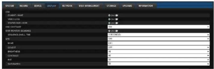
7-7-4. Display
Select the DISPLAY tab to set the DISPLAY conditions.
text_image
SYSTEM RECORD DEVICE DISPLAY NETWORK USER MANAGEMENT STORAGE UPGARE INFORMATION USD DIABETH NAME ON VEREY LOGS ON STATED BAR ICON ON USD COVERAGE ON MINI POSITION SEPARATION ON REFERENCE SHEET LINE ON SITE ON MAKE ON COUSET ON BRIGHTNESS ON CONTINATE ON BLUE ON SATuration ON ON ON ON ON ON ON ON ON ON ON ON ON ON ON ON ON ON ON ON ON ON ON ONThese settings apply to all channels.
- OSD: Sets whether to display or not, the date and time as well as channel number on the screen.
- OSD CONTRAST: Adjust the character contrast on the screen.
• MAIN MONITOR SEQUENCE: Setting for automatically switching the displayed video.
SEQUENCE DWELL TIME: Sets the interval for automatically switching the screens.
• SITE: Name, Covert, Brightness, Contrast, Hue, Saturation
These settings apply to the specified channel only.
7-7-5. Network
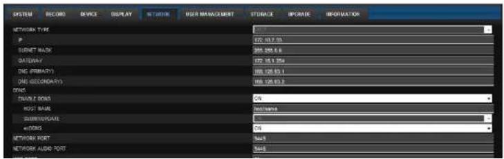
text_image
SYSTEM RECORD DEVICE DISPLAY NETON WORK MANAGEMENT STORAGE UPDATE INFORMATION NETWORK TYPE P SUPPORT MASK GATEWAY DNS (PRIMARY) DNS (SECONDARY) DNS DOUBLE SONS HOST---------BAIL SUBSTORAGE eIFRMS NETWORK PORT NETWORK AUDIO PORT7-7-6. User Management
Select the USER MANAGEMENT tab to set the DISPLAY conditions.
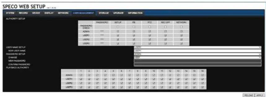
text_image
SPECO WEB SETUP SYSTEM RECORD DEVICE DISPLAY NETWORK USER MANAGEMENT STORAGE UPGRADE INFORMATION AUTHORITY SETUP PASSWORD CHECK — ADMIN — USER1 — USER2 — USER3 — PASSWORD SETUP P8 PTZ INC UPF NETWORK USER1 ADDRESS ACTION POST 1 2 3 4 5 6 7 8 9 10 11 12 13 14 15 16 ADMIN Q Q Q Q Q Q Q Q Q Q Q Q Q Q USER1 Q Q Q Q Q Q Q Q Q Q Q Q USER2 Q Q Q Q Q Q Q Q Q Q Q Q USER3 Q Q Q Q Q Q Q Q Q LOADAC APLC7-7-7. Storage
Select Storage to configure continued recording settings by overwriting the hard disk and the storage period for the recording data.
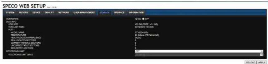
text_image
SPECO WEB SETUP SYSTEM RECORD DEVICE DISPLAY NETWORK USER MANAGEMENT STORAGE UPGNCER INFORMATION CUSTOMER DISK INFO ADD SIZE ADD LAST TIME HCG 1 MOTOR NAME TEMPORATURE HEALTH SOCIOGRAPHICAL MAC REALLOCATED SECTORS CURRENT RENDING SECTORS UNALLOCIDATE SECTORS SPAL RETORY SECTORS RECOACHING LIMIT RECOACHING LIMIT DAYS © On © Off 425 GB (FREE 431 GB) 80100000 (F10128) STOCKHOLD 24 CABBAGE (75 Patterhead) 8000 3 3 3 3 C#P RELEASE• OVERWRITE: Continues recording by writing over previous recordings when HDD is full.
- DISK INFO: Shows the information of HDD installed in DVR
7-8. Operation
7-8-1. Addition, Delete, and Modify of DVR Sites
7-8-1-1. Addition of Sites
- Click SITE ADDITION button. And then the following window will be displayed as below.

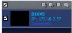
text_image
Site Addition Site Info Site name : D16VS Site address : 172.16.2.57 Port number : 5445 ID : admin Password : ****. OK CancelSite Name: Input a name that properly describes a site.
IP Address: Input IP address (Public IP address of a router that DVR is connected.) or Domain name
- Port Number: Default Port Number is "5445".
ID: Input ID of DVR. Default ID is "admin".
- Password: Input network password of DVR that is same with DVR setup password.
- Click OK button. And then the registered site is added on the directory window.

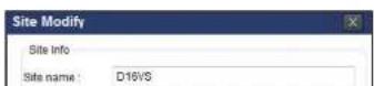
7-8-1-3. Modify of Sites
- Select the site/sites to modify from the directory window.
- Click NET FINDER button. And then the following window will be displayed as below.

text_image
Net Finder Name Address D:\16\5 172.16.2.57 Address Part No. Mac Model Add Modify Delete Find IP Change Close- Click MODIFY button. And then the modified information is displayed as below.
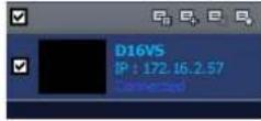
7-8-2. Connect and Disconnect
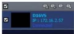
7-8-2-1. Connect
- Select site/sites to connect from the directory window.
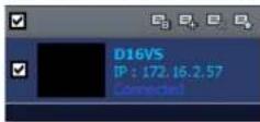
- Click CONNECT button, and then site/sites displays/display as connected.

text_image
Name: 100 Color M100 M200 M300 M400 M500 M600 M700 M800 M900 M1000 M1100 M1200 M1300 M1400 M1500 M1600 M1700 M1800 M1900 M2000 M2100 M2200 M2300 M2400 M2500 M2600 M2700 M2800 M2900 M3000 M3100 M3200 M3300 M3400 M3500 M3600 M3700 M3800 M3900 M4000 M4100 M4200 M4300 M4400 M4500 M4600 M4700 M4800 M4900 M5000 M5100 M5200 M5300 M5400 M5500 M5600 M5700 M5800 M5900 M6000 M6100 M6200 M6300 M6400 M6500 M6600 M6700 M6800 M6900 M7000 M7100 M7200 M7300 M7400 M7500 M7600 M7700 M7800 M7900 M8000 M8100 M8200 M8300 M8400 M8500 M8600 M8700 M8800 M8900 M90007-8-2-2. Disconnect
- Select site/sites to disconnect from the directory window.

7-8-3. Still-image Capture During Live
- Double-click a channel to capture from the display screen. (Otherwise all channels will be captured.).
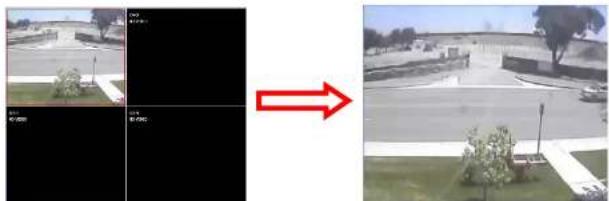
natural_image
Side-by-side comparison of two outdoor scenes: one showing a parking lot with camera, the other showing a paved road with trees and a fence (no visible text or symbols)- Click CAPTURE button. And then a Capture window will be displayed as below.
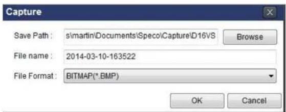
text_image
Capture Save Path: s:\martin\Documents\Specoi\Capture\D16VS Browse File name: 2014-03-10-163522 File Format: BITMAP(*.BMP) OK Cancel- Set Save Path, File Name, and File Format. And then click OK button.
- Still image is saved as set in Capture window.

text_image
Storage > Capture > D4VS Organize Include in library Share with Slide show Burn New folder Documents Music Pictures Videos7-8-4. Recording Video on Local PC During Live
- Click SETUP button. And then a setup window will be displayed as below.
- Select Record and set the values.
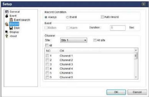
text_image
Setup General Event Event search Record Disk Display About Record Condition ● Always ○ Event □ Auto record Event □ Motion □ Alarm Duration : 5 Sec Channel Site: Site 1 □ All site □ All NO CH □ 1 Channel 1 □ 2 Channel 2 □ 3 Channel 3 □ 4 Channel 4 □ 5 Channel 5 □ 0 Channel 6 OK Cancel- Select Disk and set the values.
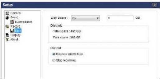
text_image
Setup General Event Event search Record Disk Display About Disk Space : C: 4 GB Disk Info Total space / 465 GB Free space / 300 GB Disk full Replace oldest files. Stop recording7-8-5. Local Playback and Remote Playback
7-8-5-1. Playback of Recorded Video on a Local PC
- Click LOCAL PLAYBACK. And then Playback Window will be displayed over the Live
Window.

text_image
SPEOD Multi Client Vol 3.0.4.6- Select site/sites to connect from the directory window.

- Click CONNECT button. And then Green bar displays on Search calendar and timeline scale window.
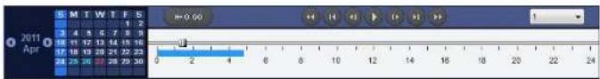
text_image
2011 April 0 2 3 4 5 6 7 8 9 10 11 12 13 14 15 16 17 18 19 20 21 22 23 24 25 26 27 28 29 30 0 2 4 6 8 10 12 14 16 18 20 22 24- Move the marker on the timeline scale to where there is video data and press the PLAY button.
7-8-5-2. Playback of Recorded Video on Remote DVR
- Click REMOTE PLAYBACK. And then Playback Window will be displayed.
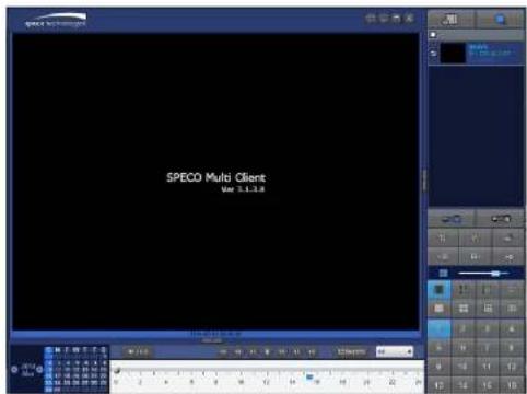
text_image
SPECO Multi Client Var 3.1.2.8-
Select the site to connect from the directory window.
-
Click CONNECT. And then Green bar displays on Search calendar and timeline scale.

text_image
2011 Apr S M T W T F S 1 2 3 4 5 6 7 8 9 16 17 18 19 20 21 22 23 24 25 26 27 28 29 30 0 2 4 6 8 10 12 14 16 18 19 20 22 24- Move the marker on the timeline scale to where there is video data and press the PLAY button.
7-8-6. AVI Backup during Playback
You can back up the recorded videos in AVI format during playback.
- Double-click the target channel to backup.
- Select the beginning time by using the search calendar and timeline scale bar.

text_image
2011 Apr S M T W T F S 3 4 5 6 7 8 9 10 11 12 13 14 15 16 17 18 19 20 21 22 23 24 25 26 27 28 29 30 0 2 4 6 8 10 12 14 16 18 20 22 24- Click EZCOPY START button on the timeline scale to select the beginning point of the backup.
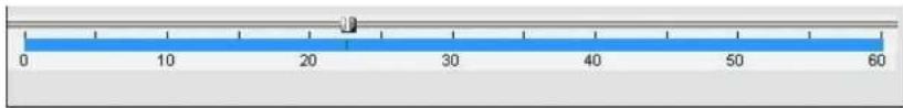
text_image
0 10 20 30 40 50 60- Click EZCOPY END button on the timeline scale to select the ending point of the backup. Then, the selected starting point and the ending point on the timeline scale bar will be marked in green.
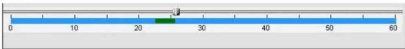
text_image
0 10 20 30 40 50 60- Click BACKUP. And then the BACKUP window will be displayed as below.
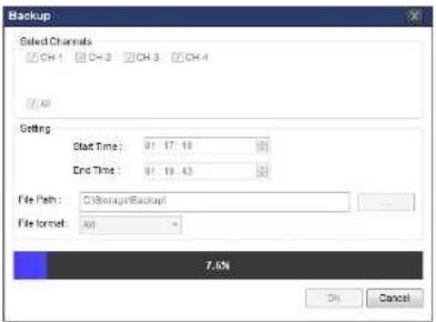
text_image
Backup Select Channels CH 1 CH 2 CH 3 CH 4 (All) Setting Start Time: 01 17.18 End Time: 01 19.43 File Path: C:\Backup\Backup\ File format: All * 7.6% On Cancel- AVI video data is recorded as selected in AVI Backup window. AVI format video can be played back by using Window Media Player™ or other media player that is compatible with AVI format video.
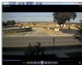
natural_image
Exterior view of a rural road with buildings and trees, no visible text or signage8. Network Access Using the Web-Browser Viewer
The DVR provides a live remote monitoring feature by web-browser viewer. (NOTE: Web-Browser is only available for Internet Explorer)
- Check the IP address of the DVR from SETUP>SYSTEM>DESCRIPTION>IP ADDRESS or
- Input the IP address or Domain name address that you pre-registered.

text_image
Address http://172.16.1.52 Go- Click this bar. Then the dialog box is displayed.

- Click "Install" to download and install the ActiveX control.
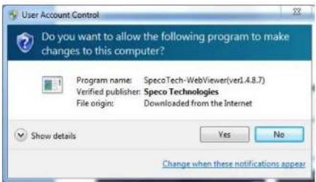
text_image
User Account Control Do you want to allow the following program to make changes to this computer? Program name: SpecoTech-WebViewer(verl.4.8.7) Verified publisher: Speco Technologies File origin: Downloaded from the Internet Show details Yes No Change when these notifications appear- The Web Browser Viewer will be displayed as below after the ActiveX installation

text_image
Space technology 2011-04-26 2:12:27
text_image
Connect -- Webpage Dialog http://192.168.1.12/login.html Connect to remote system Address 192.168.1.12 Port 5445 ID admin Password •••••| Connect Cancel- Site Name: Input a name that properly describes a site.
-
IP Address: Input IP address (Public IP address of a router that DVR is connected.) or Domain name
• Port Number: Default Port Number is "5445".
• ID: Input ID of DVR. Default ID is "admin". -
Password: Input network password of DVR that is same with DVR setup password.
- Then the cameras connected to the DVR are displayed on the screen.
- Use mouse scroll to digitally zoom in and out from a single channel display.

text_image
Live 2011-04-27 15:52:42 192.168.1.12 Image Technologies Live 2011-04-27 15:52:42 192.168.1.129. Network Access Using the Smart Phone Viewer

Notice
Data Usage applied without Wi-Fi connection. Please check with your Phone Carrier.
9-1. App Viewer for iPhone
- Enter the Apple App Store.


- Search "Speco Player" in the App Store.

Notice
SPECO Player is for the VX, VT, HT, HS, ZS, NS, DS, RS, WRS and HD series DVRs. SPECO VIEWER is not compatible with the T Series DVR's (TH, TN or TL) or the PC
9-1-1. Live
- Open the installed "Speco Player" App and click action to add a remote device.
- Enter the site name, IP or DDNS address, Network Port number (default 5445), ID(default admin) and Password that is same with DVR setup password. Then, click "Save" button.
| About | Device List | + |
| Demo DS | > | |
| Demo HS | > | |
| Demo NSP | > |

- The app will display the selected channel(s). Double tap the channel screen to switch 1 channel display to 4, 8, 10, 16 channels split display depending on the DVR.

text_image
Back LIVE 06-09-16 17:57:07 Back LIVE 06-09-16 17:57:28 NANS FPS 21 NANS FPS 30- To select the display mode(1, 4, 9, 10 or 16 split display), tap the arrow menus button
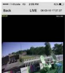
text_image
1-Mobile 0G 2:05 PM 42% Back LIVE 06-09-16 17:57:37 31:019-1-2.PTZ Control
To control the PTZ functions of the camera, tap the menu button. Then PTZ menu icons will display. Using the PTZ icon on the screen, can control PTZF functions.
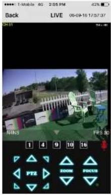
text_image
Back LIVE 06-09-16 17:57:37 N:KS 1 4 9 10 16 PTZ 200M FOCUS9-1-3. Playback
- Select mode as 'Playback' 📄 and click 'Connect' button. Then select Date & Time and click 'Connect' button.
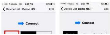
text_image
Device List Demo HS Edit Connect Device List Demo NSP Edit Connect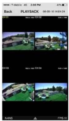
text_image
Back PLAYBACK 06-09-16 14:04:24 01:01 01:02 01:03 01:04 01:05 01:06 01:07 01:08 01:09 01:10 01:11 01:12 01:13 01:14 01:15 01:16 01:17 01:18 01:19 01:20 01:21 01:22 01:23 01:24 01:25 01:26 01:27 01:28 01:29 01:30 01:31 01:32 01:33 01:34 01:35 01:36 01:37 01:38 01:39 01:40 01:41 01:42 01:43 01:44 01:45 01:46 01:47 01:48 01:49 01:50 01:51 01:52 01:53 01:54 01:55 01:56 01:57 01:58 01:59 01:60 01:61 01:62 01:63 01:64 01:65 01:66 01:67 01:68 01:69 01:70 01:71 01:72 01:73 01:74 01:75 01:76 01:77 01:78 01:79 01:80 01:81 01:82 01:83 01:84 01:85 01:86 01:87 01:88 01:89 01:90 01:91 01:92 01:93 01:94 01:95 01:96 01:97 01:98 01:99 02:00 FPS 1→

natural_image
Outdoor scene with green canopy, chairs, and buildings under clear sky (no visible text or symbols)- Tap the menu button. Then Playback menu icons will display.
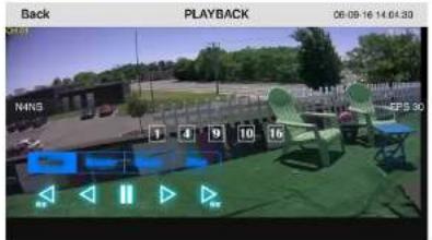
text_image
Back PLAYBACK 06-08-16 14:04:39 NANS EPS 909-2. App Viewer for Android Phone
- Enter the Android Play Store.

text_image
speco player Main menu Live Video / PlayText SmartShot Viewer Space Player
text_image
Delete MCP Delete MS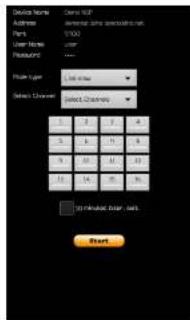
text_image
Device Name: Address: Name: Part Number: 1000 User Name: Features: Main Type: Select Channel: Select Channels: 5 6 7 8 9 10 11 12 13 14 15 16 17 18 19 20 21 22 23 24 25 26 27 28 29 30 31 32 33 34 35 36 37 38 39 40 41 42 43 44 45 46 47 48 49 50 51 52 53 54 55 56 57 58 59 60 61 62 63 64 65 66 67 68 69 70 71 72 73 74 75 76 77 78 79 80 81 82 83 84 85 86 87 88 89 90 91 92 93 94 95 96 97 98 99 100- The app will display the selected channel(s). Double tap the channel screen to switch 1 channel display to 4 channels split display.
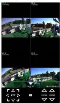
natural_image
Four-panel collage showing outdoor scenes with buildings and greenery, plus a small interface panel with icons (no readable text or symbols)- The app will display the selected channel(s). Double tap the channel screen to switch 1 channel display to 4 channels split display.

natural_image
Four-panel video editing interface showing outdoor scenes with UI overlays and playback controls (no readable text or symbols)9-2-3.PTZ Control
To control the PTZ function of the camera, tap the channel screen, and then the channel name will be highlighted in Light Green. Using the PTZ menu icons on the screen, control PTZF.
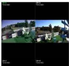
natural_image
Two-panel image showing a residential scene with houses and a person, no visible text or symbols.APPENDIX: Network Connection - LAN
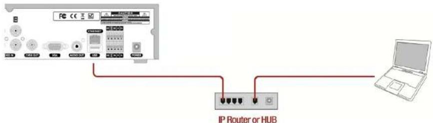
text_image
IP Router or HUB- Install the network client software from the supplied CD.
- Check the IP address from SETUP > SYSTEM > DESCRIPTION or SETUP > NETWORK of DVR.
| Model Name | D16VX |
| Software Version | Ver 5.3.1N_20161209 |
| Storage Size | 3645 GB |
| IP Address | 172.16.2.2 |
| MAC Address | 00:02:69:0B:06:E4 |
| DDNS Status | Ready - d16vx_0b06e4 |
- Run the network client software.


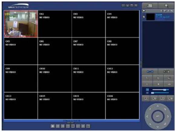
APPENDIX: Network Connection – Internet and DDNS
Dynamic Domain Name System (DDNS) allows a domain name to be constantly synchronized with a dynamic IP address. A current dynamic IP address is being associated with a static domain name.

flowchart
graph TD
    A["PC"] -->|Internet| B["Internet"]
    C["ADSL"] -->|Internet| B
    D["IP Router or HUB"] -->|Internet| B
    E["Laptop"] -->|Internet| B
- Go to SETUP>NETWORK>DDNS and set the DDNS SERVER to ON.
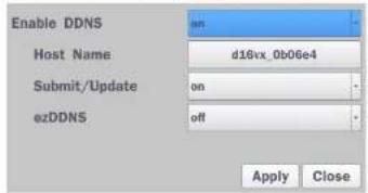
text_image
Enable DDNS Host Name d18vx_0b06e4 Submit/Update on ezDDNS off Apply CloseIf you set ezDDNS to ON, the host name is automatically generated and registered.
-
Go to SETUP>NETWORK>DDNS>HOST NAME. Manually enter a domain name using the virtual keyboard and click ENTER button.
-
When DDNS setting is done, click the APPLY button. Otherwise DDNS setting will not be applied.
- When you exit SETUP menu, DDNS NOTIFY window will pop up.
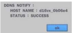
text_image
DDNS NOTIFY : HOST NAME : d16vx_0b06e4 STATUS : SUCCESS ok- DDNS registration status can be checked from SYSTEM INFORMATION or SETUP>SYSTEM>DESCRIPTION>DDNS STATUS

text_image
Model Name D16VX Software Version Ver 5.3.1N_20161209 Storage Size 3645 GB IP Address 172.16.2.2 MAC Address 00:02:69:0B:06:E4 DDNS Status Ready - d16vx_0b06e4 ok- Check the NETWORK PORT (Default: 5445), WEB PORT (Default: 80), and the IP Address of the DVR from SETUP>NETWORK.

text_image
Network Network Type IP Subnet Mask Gateway DNS (Primary) DNS (Secondary) dhcp 172.16.2.17 255.255.0.0 172.16.1.254 168.126.63.1 168.126.63.2- Run the network client software.
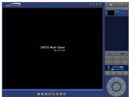
text_image
SPECO Multi Client Wu 3.1.18
text_image
Site Addition Site Info Site name: D16V0 Site address: 172.18.267 Port number: 5445 D: sown Password: **** OK Cancel-
Input Site Name, Site Address (IP address), Port No., and Password on the connect window.
-
Site Name: Input a name that properly describes a site.
• IP Address: Domain name or Public IP address of a router that DVR is connected.
• Port Number: Default Port Number is "5445".
• ID: Input ID of DVR. Default ID is "admin". -
Password: Input network password of DVR that is same with DVR setup password.
-
And select the OK button. Then, press button after checking the left check box.