D4CX2TB - Security Camera Speco Technologies - Free user manual and instructions
Find the device manual for free D4CX2TB Speco Technologies in PDF.

User questions about D4CX2TB Speco Technologies
0 question about this device. Answer the ones you know or ask your own.
Ask a new question about this device
Download the instructions for your Security Camera in PDF format for free! Find your manual D4CX2TB - Speco Technologies and take your electronic device back in hand. On this page are published all the documents necessary for the use of your device. D4CX2TB by Speco Technologies.
USER MANUAL D4CX2TB Speco Technologies
Operation Instruction
NO USER-SERVICEABLE PARTS INSIDE.
REFER SERVICING TO QUALIFIED
SERVICE PERSONNEL.

The lightning flash with arrowhead symbol, within an equilateral triangle, is intended to alert the user to the presence of uninsulated "dangerous voltage" within the product's enclosure that may be of sufficient magnitude to constitute a risk of electric shock.
The exclamation point within an equilateral triangle is intended to alert the user to the presence of important operating and maintenance (servicing) instructions in the literature accompanying the appliance.
COMPLIANCE NOTICE OF FCC:
THIS EQUIPMENT HAS BEEN TESTED AND FOUND TO COMPLY WITH THE LIMITS FOR A CLASS A DIGITAL DEVICE, PURSUANT TO PART 15 OF THE FCC RULES. THESE LIMITS ARE DESIGNED TO PROVIDE REASONABLE PROTECTION AGAINST HARMFUL INTERFERENCE WHEN THE EQUIPMENT IS OPERATED IN A COMMERCIAL ENVIRONMENT. THIS EQUIPMENT GENERATES, USES, AND CAN RADIATE RADIO FREQUENCY ENERGY AND IF NOT INSTALLED AND USED IN ACCORDANCE WITH THE INSTRUCTION MANUAL, MAY CAUSE HARMFUL INTERFERENCE TO RADIO COMMUNICATIONS. OPERATION OF THIS EQUIPMENT IN A RESIDENTIAL AREA IS LIKELY TO CAUSE HARMFUL INTERFERENCE, IN WHICH CASE USERS WILL BE REQUIRED TO CORRECT THE INTERFERENCE AT THEIR OWN EXPENSE.
WARNING: CHANGES OR MODIFICATIONS NOT EXPRESSLY APPROVED BY THE PARTY RESPONSIBLE FOR
Important Safeguards
- Read Instructions
All the safety and operating instructions should be read before the appliance is operated.
- Retain Instructions
The safety and operating instructions should be retained for future reference.
- Cleaning
Unplug this equipment from the wall outlet before cleaning it. Do not use liquid aerosol cleaners. Use a damp soft cloth for cleaning.
- Attachments
Never add any attachments and/or equipment without the approval of the manufacturer as such additions may result in the risk of fire, electric shock or other personal injury.
- Water and/or Moisture
Do not use this equipment near water or in contact with water.
- Placement and Accessories
Do not place this equipment on an unstable cart, stand or table. The equipment may fall, causing serious injury to a child or adult, and serious damage to the equipment.

This equipment and cart combination should be moved with care. Quick stops, excessive force, and uneven surfaces may cause the equipment and cart combination to overturn.
Do not place this equipment on a closed space. Sufficient amount of ventilation air is necessary to avoid increase of ambient temperature which can cause improper operation or the risk of fire.
- Power Sources
This equipment should be operated only from the type of power source indicated on the marking label. If you are not sure of the type of power, please consult your equipment dealer or local power company.
- Power Cords
Operator or installer must remove power and TNT connections before handling the equipment.
- Lightning
For added protection for this equipment during a lightning storm, or when it is left unattended and unused for long periods of time, unplug it from the wall outlet and disconnect the antenna or cable system. This will present down to the equipment, but in lightning,
- Overloading
Do not overload wall outlets and extension cords as this can result in the risk of fuse or electric shock.
- Objects and Liquids
Never push objects of any kind through openings of this equipment as they may touch dangerous voltage points or short out parts that could result in a fire or electric shock. Never spill liquid of any kind on the equipment.
- Servicing
Do not attempt to service this equipment yourself. Refer all servicing to qualified service personnel.
- Damage requiring Service
Unplug this equipment from the wall outlet and refer servicing to qualified service personnel under the following conditions:
A. When the power-supply cord or the plug has been damaged.
B. If liquid is spilled, or objects have fallen into the equipment C. If the equipment has been exposed to rain or water.
D. If the equipment does not operate normally by following the operating instructions, adjust only those controls that are covered by the operating instructions as an improper adjustment of other controls may result in damage and will often require extensive work by a qualified technician to restore the equipment to its normal operation.
E. If the equipment has been dropped, or the cabinet damaged.
F. When the equipment exhibits a distinct change in performance, this indicates a need for service.
- Replacement Parts
When replacement parts are required, be sure the service technician has used replacement parts specified by the manufacturer or that have the same characteristics as the original part. Unauthorized substitutions may result in fire, electric shock or other hazards.
- Safety Check
Upon completion of any service or repairs to this equipment, ask the service technician to perform safety checks to determine that the equipment is in proper operating condition.
- Field Installation
This installation should be made by a qualified service person and should conform to all local codes.
- Correct Batteries
Warning: Risk of explosion if battery is replaced by an incorrect type. Dispose of used batteries according to the instructions.
- Tmra
A manufacturer's maximum recommended ambient temperature (Tmra) for the equipment must be specified so that the customer and installer may determine a suitable maximum operating environment for the equipment.
Table of Contents
Chapter 1 — Introduction....1
Feature....1
Technical Overview....1
Chapter 2 — Installation....3
Package Contents....3
Required Installation Tools 3
Video Input 3
Audio In/Out 4
Alarm Input/Output 4
RS485 Port 4
RS232 Port 4
Network Port 5
Video Out 5
Factory Reset Switch.... 5
Power Cord Connector 5
Chapter 3 — Configuration .... 7
Front Panel Controls 7
Menu Button 7
Copy Button....7
Esc Button 7
Play/Stop Button 8
Camera Buttons....8
Arrow Buttons 8
Play/Pause Button 8
HDD LED 8
Power LED 8
USB Port 8
Remote Control Buttons....9
ID Button....9
Camera Buttons....9
Sequence Button 9
Login/Logout Button 9
Operation Instruction
Setup Screen 12
System Setup.... 13
General 15
Date/Time 20
User 22
Storage 24 Capacity Estimator 25
Capacity Estimator 25 System Event 25
System Event 25
Recording Setup 27
General 27
Schedule 28
Pre-Event 30
Event Setup 31
Motion 31
Alarm-In 32
Video Loss 33
Video Blind.... 33
Text-In....34
Camera Setup 36
General 36
PTZ 37
Device Setup.... 38
Audio....38
Digital Deterrent 38
Alarm-Out 40
Remote Control 41
Network Setup 41
General 41
LAN 42
DVRNS 44
RTSP 45
Speco Remote 46
VNC 46
Notification Setup....47
Callback 47
Mail 48
SNS 50
Digital Video Recorder
Status Monitoring....60
Recording Video 61
Panic Recording 61
Recording Audio 62
Playing Recorded Video 62
Searching Video....63
Search Menu 63
Event Log Search 65
Record Table Search....67
Motion Search 68
Text-In Search 70
EZ Search 71
Bookmarks....72
Clip-Copy 72
Print 74
Appendix 75
USB Hard Disk Drive Preparation 75
Text-In Search Examples....75
Search Example I 75
Search Example II 76
Speco Remote 77
Web Monitoring Mode 78
Web Search Mode 79
Time Overlap 81
Error Code Notices 81
System Log Notices 82
Map of Screens 83
Troubleshooting 84
Specifications....84
List of Illustrations
Operation Instruction
Figure 17: Record – Pre-Event setup screen....30
Figure 18: Event – Motion setup screen....31
Figure 19: Event – Alarm in act-up screen....22
Figure 19: Event – Alarm-in setup screen....32
Figure 20: Event – Video Loss setup screen....33
Figure 21: Event – Video Blind setup screen....33
Figure 22: Event – Text-In setup screen. 34
Figure 23: Camera – General setup screen....36
Figure 24: Camera – PTZ setup screen....37
Figure 25: Device – Audio setup screen. .... 38
Figure 26: Device – Digital Detergent setup screen. .... 38
Figure 28: Device - Digital Different setup screen....38
Figure 27: Device - Alarm-Out setup screen....40
Figure 28: Device – Remote Control setup screen. 41
Figure 29: Network – General setup screen....41
Figure 30: Network – LAN setup screen. 42
Figure 31: Network – DVRNS setup screen....44
Figure 32: Network – RTSP setup screen....45
Figure 33: Network – Speco Remote setup screen....46
Figure 34: Network – VNC setup screen....46
Figure 35: Notification – Callback setup screen....47
Figure 36: Notification – Mail setup screen. 48
Figure 37: Notification - CNS setup screen. 50
Figure 37: Notification – SNS setup screen. ....50
Figure 38: Notification – Schedule setup screen. ....50
Figure 39: Display – OSD setup screen 51
Figure 40: Display – Main Monitor setup screen 52
Figure 41: Live Monitoring menu....55
Figure 42: PTZ Select Camera menu. 58
Figure 43: PTZ Preset menu....59
Figure 44: Event Status – Event Status screen....60
Figure 45: Event Status – Storage screen. 61
Figure 46: Select Playback Camera menu....62
Figure 47: Search menu....63
Figure 48: Event Log Search screen....65
Figure 49: Record Table Search screen. 67
Figure 50: Motion Search screen....68
Figure 51: Text-in Search screen....70
Figure 52: Desktop screen....70
Figure 52: Bookmarks screen....72
Figure 53. Clip Copy screen. 73
Figure 54. Print paper. 74
Chapter 1 — Introduction
Feature
Your color digital video recorder (DVR) provides recording capabilities for four or eight camera inputs. It provides exceptional picture quality in both live and playback modes, and offers the following features:
• 4 or 8 Composite Video Input Connectors
• Compatible with Color (NTSC or PAL.) and B&W (CCIR and EIA-170) Video Sources
• Auto Detection for NTSC and PAL
• H.264 Codec
• Monitor Connectors: 1 HDMI, 1 VGA
• Multiple Search Engines (Date/Time, Calendar, Record Table, Event, EZ Search)
• Real-time Recording (240/200 Images per Second (NTSC/PAL) with Very High (D1/960H) Resolution)
• Continuous Recording in Disk Overwrite Mode
• 2 USB 2.0 Ports
• Continues Recording while Transmitting to Remote Site and during Playback
- User-friendly Graphical User Interface (GUI) Menu System
• Multiple Recording Modes (Time-lapse, Pre-event, Alarm, Motion and Panic)
- Two-way Audio Communication
• 4-Channel Audio Recording and 1-Channel Audio Playback
• Text Input for ATM and POS
• Alarm Connections Include: Input, Output
• Built-in Alarm Buzzer
• Live or Recorded Video Access via Ethernet
• Time Synchronization using industry standard protocol
- IR Remote Control
• Self-diagnostics with automatic notification including hard disk drive S.M.A.R.T. protocol
Technical Overview
In addition to replacing both a time-lapse VCR and a multiplexer in a security installation, your DVR has many features that make it much more powerful and easier to use than even the most advanced VCR.
The DVR converts analog NTSC or PAL video to digital images and records them on a hard disk drive. Using a hard disk drive allows you to access recorded video almost instantaneously: there is no need to rewind tape. The technology also allows you to view recorded video while the DVR continues recording video.
Operation Instruction

flowchart
graph TD
    A["Cameras (1-8)"] --> B["Digital Video Receiver"]
    C["Audio Input (1-4)"] --> B
    D["Audio Output"] --> B
    E["IR Remote Control"] --> B
    F["ATM/POS"] --> B
    G["Remote Keyboard"] --> B
    H["Mouse"] --> B
    I["Network"] --> B
    J["SpeechoCentral II"] --> B
    K["SpeechoRemote"] --> B
    L["Flash Drive"] --> B
    M["USB HDD"] --> B
    N["Flashing Light"] --> B
    O["Sires"] --> B
    P["Alarm Output"] --> B
Figure 1: Typical DVR installation.
NOTE: This manual covers the 4- and 8-channel digital video recorders. The DVRs are identical except for the number of cameras and alarms that can be connected and the number of cameras that can be displayed. For simplicity, the illustrations and descriptions in this manual refer to the 8-camera model.
Chapter 2 — Installation
Package Contents
The package contains the following:
• Digital Viden Recorder
• Power Adaptor and Power Cord
• Operation Instruction (This Document)
- Speech Central Software CD and Operation Instruction
• Infrared Remote Control
Required Installation Tools
No special tools are required to install the DVR. Refer to the installation manuals for the other items that make up part of your system.

text_image
Diagram of a device rear panel with labeled ports and indicators, showing connections between ports like USB, network, and power.Figure 2: 8-Channel DVR rear panel.
① Video Input
⑤ RS232 Port
⑨ Power Cord Connector
② Audio In'Out
④ Network Port
③ Alarm Input/Output
⑦ Video Out
④ RS485 Port
⑥ Factory Reset Switch
Your DVR can be used with either NTSC or PAL equipment.
NOTE: You cannot mix NTSC and PAL equipment. For example you cannot use a PAL camera and an NTSC monitor.
Operation Instruction
Audio In/Out
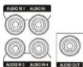
Your DVR can record audio from up to four sources. Connect the audio sources to Audio In 1, Audio In 2, Audio In 3 and Audio In 4 as needed using RCA jacks. Connect Audio Out to your amplifier.
NOTE: It is the user's responsibility to determine if local laws and regulations permit recording audio.
The DVR does not have amplified audio output, so you will need a speaker with an amplifier. The DVR does not have a pre-amplifier for audio input, so the audio input should be from an amplified source, not directly from a microphone.
Alarm Input/Output
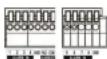
NOTE: To make connections on the Alarm Connector Strip, press and hold the button and insert the wire in the hole below the button. After releasing the button, tug gently on the wire to make certain it is connected. To disconnect a wire, press and hold the button above the wire and pull out the wire.
Alarm In 1 to 8: You can use external devices to signal the DVR to react to events. Mechanical or electrical switches can be wired to the Alarm In and GND (Ground) connectors. The threshold voltage of electrical switches for NC (Normally Closed) is above 2.4V and for NO (Normally Open) is below 0.3V, and should be stable at least 0.5 seconds to be detected. The voltage range of alarm input is from 0V to 5V. See Chapter 3 - Configuration for configuring alarm input.
GND (Ground): Connect the ground side of the Alarm input and/or alarm output to the GND connector.
NOTE: All the connectors marked GND are common.
NO (Normally Open): Connect the device to the COM and NO (Normally Open) connector. NO is a relay output which sinks 1A@30VDC. See Chapter 3 - Configuration for configuring alarm output.
Connector Pin Outs:
| Alarm In (1 to 8) | Alarm Inputs 1 to 8 |
| GND | Chassis Ground |
| COM | Relay Common |
| NO | Relay Alarm Out (Normally Open) |
RS485 Port

The DVR can be controlled remotely by an external device or control system, such as a control keyboard, using RS485 half-duplex serial communications signals. The RS485 connector can also be used to control
Digital Video Recorder
Connector Pin Outs:
| Master Unit Slave Unit | ||||
| RX | → | To | → | TXD |
| TX | → | To | → | RXD |
| GND | → | To | → | GND |
NOTE: Refer to the following for pin-out details for the 9-pin connector of the slave unit.


| Pin 2 | RXD (Receive Data) |
| Pin 3 | TXD (Transmit Data) |
| Pin 5 | GND (Ground) |
Network Port

The DVR can be networked using the 10Mlb/100Mlb/1Gb Ethernet connector. Connect a Cat5 cable with an RJ-45 jack to the DVR connector. The DVR can be networked with a computer for remote monitoring, searching, configuration and software upgrades. See Chapter 3 - Configuration for configuring the Ethernet connections.
CAUTION: The network connector is not designed to be connected directly with cable or wire intended for outdoor use.
Video Out


A VGA connector is provided so that you can use a standard, multi-sync computer monitor as your main monitor. Use the cable supplied with your monitor to connect it to the DVR.
An HDMI (High-Definition Multimedia Interface) connector is provided so that you can use an HDMI monitor as your main monitor.
NOTE: Connect the monitor before the DVR boots so that video can be displayed on the monitor with the resolution you have set during system setup. If you want to use both the HDMI and VGA Monitor connectors, one of the monitors should be connected before the DVR boots, and the other monitor should be connected after the DVR boots.
Factory Reset Switch

The DVR has a Factory Reset switch to the left of the HDMI connector on the rear panel. This switch will only be used on the rare occasions that you want to return all the settings to the original factory settings.
CAUTION: When using the Factory Reset, you will lose any settings you have saved.
Operation Instruction
WARNING: ROUTE POWER CORDS SO THAT THEY ARE NOT A TRIPPING HAZARD. MAKE CERTAIN THE POWER CORD WILL NOT BE PINCHED OR ABRADED BY FURNITURE. DO NOT INSTALL POWER CORDS UNDER RUGS OR CARPET. THE POWER CORD HAS A GROUNDING PIN. IF YOUR POWER OUTLET DOES NOT HAVE A GROUNDING PIN RECEPTACLE, DO NOT MODIFY THE PLUG. DO NOT OVERLOAD THE CIRCUIT BY PLUGGING TOO MANY DEVICES IN TO ONE CIRCUIT.
CAUTION: Ensure the DVR is not near any heat source that could cause overheating.
CAUTION: The DVR does not have an internal fan so leave a clearance of at least 6 inches near ventilation hole areas on each side panel of the unit for proper ventilation.
Your DVR is now ready to operate. Refer to Chapter 3 - Configuration and Chapter 4 - Operation.
Digital Video Recorder
Chapter 3 — Configuration
NOTE: Your DVR should be completely installed before proceeding. Refer to Chapter 2 — Installation.
Front Panel Controls
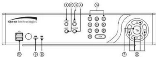
text_image
speco technologies ①②③④ ⑤ ⑥ ⑦ ⑧ ⑨ ⑩ ⑪ ⑫ ⑬ ⑭ ⑮ ⑯ ⑰ ⑱ ⑲ ⑳ ㉑ ㉒ ㉓ ㉔ ㉕ ㉖ ㉗ ㉘ ㉙ ㉚ ㉛ ㉜ ㉝ ㉞ ㉟ ㉳ ㉻ ㉼ ㉖ ㉗ ㉘ ㉙ ㉚ ㉛ ㉜ ㉝ ㉞ ㉟ ㉓ ㉔ ㉕ ㉖ ㉗ ㉘ ㉙ ㉚ ㉛ ㉜ ㉝ ㉞ ㉟ ㉓ ㉔ ㉕ ㉖ ㉗ ㉘ ㉙ ㉚ ㉛ ㉜ ㉝ ㉞ ㉟ ㉓ ㉔ ㉕ ㉖ ㉗ ㊱Figure 3: 8-Channel DVR front panel.
① Menu Button
⑤ Camera Buttons
⑨ Power LED
② Copy Button
⑥ Arrow Buttons
USB Port
③ Esc Button
② Play:Pause Button
④ Play/Stop Button
⑧ HDD LED
The front panel looks and operates much like a VCR combined with a multiplexer. The following describes each button and control. Take a few minutes to review the descriptions. You will use these to initially set up your DVR and for daily operations.
NOTE: A separate Alarm button on the front panel is not provided. Pressing any button on the front panel resets alarm output including the internal buzzer when the alarm is activated. However, when you are in the menu or PTZ mode, you have to exit the menu or PTZ mode first to reset alarm output.
The infrared sensor on the DVR is just to the right of the USB ports. Make certain that nothing blocks the sensor, or the remote control will not function properly.
When you use wireless communication devices (such as Wi-Fi or Bluetooth) near the DVR, the remote control might not function properly.
You can also use a USB mouse (not supplied) to navigate through the screens and menus much like you would on a computer.
Henry Button
Operation Instruction
Play/Stop Button
Pressing the PLAY/STOP button enters the playback mode, and pressing the button again exits the playback mode. When entering the playback mode, video is paused. Pressing the (Play/Pause) button plays back video at regular speed. The screen displays II when the DVR is in the Pause mode and the screen displays ▶ when the DVR is playing back video. When in one of the multi-view formats, pressing this button enters the Triplex mode. The DVR supports the Triplex function: monitoring, recording and playing back at the same time.
Camera Buttons
Pressing the individual camera buttons will cause the selected camera to display full screen. Buttons 1 to 9 are also used to enter passwords.
Arrow Buttons
These buttons are used to navigate through menus and GUI. You can also use them to change numbers by highlighting a number in the menu and using the Up and Down arrow buttons to increase or decrease the number's value. When in the PIP display format, pressing the Up and Down arrow buttons moves the position of the small screen counter-clockwise and clockwise, and pressing the Left and Right buttons changes the PIP screen size.
In the playback mode, pressing the button plays video backward at high speed. Pressing the button again toggles the playback speed from and the screen displays and respectively. Pressing the button plays video forward at high speed. Pressing the button again toggles the playback speed from. The screen displays respectively. When in the pause mode, pressing the button moves to the next image and pressing the button moves to the previous image.
Play/Pause Button
In the live monitoring mode, pressing the ⓣ button freezes the current screen and the screen displays ⚙ icon. When in the playback mode, pressing the ⚣ button plays back images at regular speed or pauses playing video. Pressing the ⚣ button selects a highlighted item or completes an entry that you have made during system setup.
HDD LED
The HDD LED flickers when the DVR is recording or searching video on the hard disk drive.
Power LED
Digital Video Recorder
Remote Control Buttons
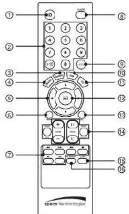
text_image
① ② ③ ④ ⑤ ⑥ ⑦ ⑧ ⑨ ⑩ ⑪ ⑫ ⑬ ⑭ ⑮ ⑯ ⑰ ⑱ ⑲ ⑳ ⑴ ⑵ ⑶ ⑷ iSPCO technabogiet① ID Button
② Camera Buttons
③ Sequence Button
④ Login/Logout Button
⑤ Arrow Buttons
⑥ Menu Button
⑦ Playback Buttons
⑧ Alarm Button
⑨ Layout Button
@ Zoom Button
⑪ PTZ Button
⑫ Enter Button
⑬ Esc Button
⑭ PTZ Control Buttons
⑯ Copy Button
⑯ Play/Stop Button
Figure 4: Infrared remote control.
NOTE: For simplicity, the button descriptions in this manual refer to the front panel buttons.
ID Button
If a DVR System ID is set to 0, the infrared remote control will control that DVR without any additional operations. (Refer to the System - General setup screen in this chapter for further information on setting the System ID.) If the system ID is 1 to 16, you must to press the ID button and then press the number button (1 to 16 (+10 & 6)) in order to control that DVR. If the System ID of two or more DVRs is set to 0, these DVRs will react in the infrared remote control at the same time.
Operation Instruction
Arrow Buttons
These buttons are used to navigate through menus and GUI. You can also use them to change numbers by highlighting a number in the menu and using the Up and Down arrow buttons to increase or decrease the number's value.
When in the PIP display format, pressing the Up and Down arrow buttons moves the position of the small screen counter-clockwise and clockwise.
Pressing the Left and Right buttons moves through screen pages in the Live Monitoring mode and Search mode.
Menu Button
In the Live Monitoring mode and Search mode, pressing the MENU button displays the menu icons on the right edge of the screen.
Playback Buttons
- Rewind: Pressing the button plays video backward at high speed. Pressing the button again toggles the playback speed from .
- Play/Pause: Pressing the button plays back video at regular speed and pressing the button again pauses video. The screen displays || when the DVR is in the Pause mode and the screen displays ▶ when the DVR is playing back video.
- Fast Forward: Pressing the button plays video forward at high speed. Pressing the button again toggles the playback speed from ▶, ▶, ▶
- Stop: Pressing the ■ button stops playback and enters the Live Monitoring mode.
- Backward: When in the pause mode, pressing the button moves to the previous image.
- Forward: When in the pause mode, pressing the ▶ button moves to the next image.
In the Live Monitoring mode, pressing any playback button enters to the Search mode.
Alarm Button
Pressing the ALARM button resets the DVR's outputs including the internal buzzer during an alarm.
Layout Button
Pressing the LAYOUT button toggles between different display formats. The available formats are: 3x3, 1P7, 1P5, 2x2 and PIP.
Zoom Button
Digital Video Recorder
Esc Button
During menu setup, pressing the ESC button closes the current menu or setup dialog box.
PTZ Control Buttons
While in the PTZ mode, the PRESET buttons are used to save Presets and load a Preset View, the ZOOM buttons are used to Zoom In and Zoom Out, and the FOCUS buttons are used for Near Focus and Far Focus.
Copy Button
Pressing the COPY button allows you to copy video clips.
Play/Stop Button
Pressing the PLAY/STOP button enters the playback mode, and pressing the button again exits the playback mode. When entering the playback mode, video is paused. Pressing the button plays back video at regular speed. The screen displays when the DVR is in the Pause mode and the screen displays when the DVR is playing back video.
When in one of the multi-view formats, pressing this button enters the Triplex mode. The DVR supports the Triplex function: monitoring, recording and playing back at the same time.
Turning on the Power
Connecting the power cord to the DVR turns on the unit. The unit takes approximately 50 seconds to initialize.
Initial Unit Setup
Before using your DVR for the first time, you will want to establish the initial settings. This includes items such as time and date, display language, camera, remote control, record mode, network and password. Your DVR can be set up using various screens and dialog boxes.
Throughout the screens you will see 📄. Highlighting the 🔒 and pressing the Ⓧ button gives you the opportunity to reset that screen to its default settings.

Highlighting This page or All pages and pressing the Ⓧbutton resets the current page or all pages of the screen to its or their default settings.
Operation Instruction
NOTE: To assure the secure management of the system, setting up a password is strongly recommended.
If you cannot use the front panel buttons, click the button using the mouse to enter a password, and the virtual keyboard displays. See instructions below for using the virtual keyboard.
To log the user out of the system, press the MENU button or move the mouse pointer on the right edge of the screen and then select (Logout) in the Live Monitoring menu. The Logout screen displays asking you to confirm whether or not you want to log out the current user.

Figure 6: Logout screen.
Setup Screen

text_image
① SYSTEM ② ③ ④ ⑤ ⑥ ⑦ ⑧① System
② Record
③ Event
④ Camera
⑤ Device
⑥ Network
⑦ Notification
⑧ Display
Figure 7: Setup screen.
Press the MENU button or move the mouse pointer on the right edge of the screen and then select (Setup) in the Live Monitoring menu to enter the setup screen.
While setting up the DVR, there will be many opportunities to enter names and titles. When making these entries, a Visual Basic and all names
Digital Video Recorder
System Setup
General
text_image
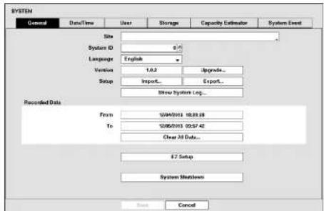
SYSTEM General Data/Time User Storage Capacity Estimator System Event Site System ID 2 Language English Version 1.0.2 Upgrade... Setup Import Export... Browse System Log... Recorded Data From 10/04/2013 18:28:28 To 10/05/2013 00:57:42 Clear All Data... E2 Setup System Shutdown Save CancelFigure 8: System - General setup screen.
Highlight the Site box and press the Ⓧ button. A virtual keyboard appears that you can use to enter a Site Name. Once you have entered your title, highlight OK and press the Ⓧ button.
Highlight the box beside System ID and press the Ⓧ button. Change the number by highlighting it and using the Up and Down arrow buttons to increase and decrease the number from 0 to 99.
NOTE: The System ID number is used to identify the unit when it is connected with other DVRs through the RS485 port. You cannot use the same ID number for two or more DVRs that are in the same RS485 network. It is possible to have multiple DVRs with System ID 0 that are in the same area as long as they are not part of an RS485 network. If this is the case, all will be controlled at the same time when using the infrared remote control.
Highlight the box beside Language and press ⏻ button. A drop-down menu displays the available languages. Highlight the desired language and press the ⏻ button.
The box beside Version displays the software version of the DVR. To upgrade the software, connect a USB device containing the upgrade package file to the DVR. Highlight Upgrade... and press the ⏻ button. The Upgrade screen appears. The screen displays the upgrade package file names that are available. The “rul” indicates that the file is for
Operation Instruction
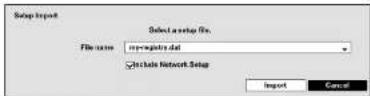
You can import saved DVR settings or export the current DVR settings. To import saved DVR settings, connect the USB device containing the setup file (.dat) to the DVR. Highlight Setup – Import... and press the button. Select the desired setup file and press the Import button to import the selected settings and change the DVR settings accordingly. Highlight Include Network Setup and press the button to toggle between On and Off. When set to Off, the network settings will not be changed.
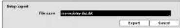
To export the current DVR settings, connect the USB device to the DVR. Highlight Setup - Export... and press the button. Highlight the box beside File name and press the button. A virtual keyboard allows you to enter the file name. Selecting Export will save the current settings in .dat file format on the USB device.
NOTE: Even after changing the DVR settings by importing saved settings, the time-related settings (Date: Time, Time Zone and Daylight Saving Time) will NOT be changed.
CAUTION: The USB device must be FAT16 or FAT32 format.
Highlight Show System Log... and press the ⏻ button to display the System Log.

text_image
Setup Log Time 00:00:01 16:54:11 00:00:01 16:55:00 00:00:01 16:55:00 00:00:01 16:55:05 00:00:01 16:56:04 00:00:01 16:56:02 00:00:01 16:56:05 00:00:01 16:56:01 00:00:01 16:56:39 00:00:01 16:56:38 00:00:01 16:56:39 00:00:01 16:56:39 00:00:01 16:56:39 00:00:01 16:56:39 00:00:01 16:56:39 00:00:01 16:56:39 Stop Setup Setup Begin Logist address Logist address Search End Stop Setup Setup Begin Logist address Disk at :S/O/CY/TSR 1/2 Export...Digital Video Recorder
The box beside Recorded Data – From / To displays the time information of recorded data.
Highlighting Clear All Data... and pressing the button will clear all video data. You will be asked to verify that you wish to clear all data before the DVR erases the video data. Clear All Data... will not clear the System Log.
Highlight EZ Setup and press the Ⓧ button. The EZ Setup screen appears. The EZ Setup guides you through configuring the system for basic operation.

text_image
Select EZ Setup EZ Setup will help you to setup your DWF. Please select one of the options below. • EZ Record for TimeDate and Recording Setup • EZ Network for Network Setup Cancel NextSelect either EZ Record or EZ Network and select the Next button to start the selected setup.
NOTE: Selecting the Cancel button throughout the screens exits the EZ Setup without saving your changes and returns to the main setup screen.

text_image
EZ Record You are about to start EZ Record. EZ Record will guide you through: - Schedule Time Setup - Recording Method Setup - Recording Video Quality Setup - Network Setup (Optional) Click the Tour button to start EZ Record.Operation Instruction
text_image
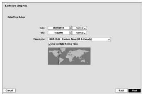
EZRecord (Step 10) Data/Time Setup Date 06/23/2013 Format Time 11:59:00 Format Time Zone GMT-05:00 Eastern Time (US & Canada) Use Doaltight Saving Time Cancel Back NextDate:Time Setup
- Date: Set the system date and select the date format.
• Time: Set the system time and select the time format. - Time Zone: Select your time zone. The Time Zone can be selected on the map.
- Use Daylight Saving Time: Selecting the box sets the system to use daylight saving time.
NOTE: The Date/Time will be set, and the clock will start when you click the Next button.
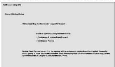
text_image
E2 Record (Step 10) Record Method Setup Which recording method would you prefer to use? • Motion Event Record (Recommended) • Continuous & Motion Event Record • Continuous Record Motion Event Record means that the system will record when a Motion Event is detected. Generally, where quality is more important for Motion Event recording than it is for Continuous Recording, so the system records at a higher quality for Motion Events.Digital Video Recorder
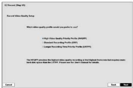
text_image
E2 Record (Step 30) Record Video Quality Setup Which video quality profile would you prefer to use? • High Video Quality Priority Profile (HVAPP) • Standard Recording Profile (SRP) • Longer Recording Time Priority Profile (LRTPP) The HVAPP provides the highest video quality recording at that highest frame rate but requires more hand-disk space than the LRTPP. Please see the User's manual for details. Cancel Back NextRecord Video Quality Setup
- Select the desired video quality profile from:
– Higher Video Quality Priority Profile
- Standard Recording Profile - Longer Recording Time Priority Profile
NOTE: The higher quality setting requires more storage space.
The recording resolution will be set to Very High (D1/960H) when selecting High Video Quality Priority Profile, High (2CIF/H960H) when selecting Standard Recording Profile, and Standard (CIF/Q960H) when selecting Longer Recording Time Priority Profile.
The recording quality and recording speed of each camera channel will be set as show below according to the Record Method and Record Video Quality you set.
| HVOPP* SRP* LRTPP* | |||
| Motion Event Record | Very High / 30 ips High / 5 ips Standard / 3 ips | ||
| Continuous & Motion Event Record | Very High / 30 ips (Time) Very High / 30 ips (Event) | High / 5 ips (Time) Very High / 30 ips (Event) | Standard / 3 ips (Time) High / 5 ips (Event) |
| Continuous Record | Very High / 30 ips High / 5 ips Standard / 3 ips | ||
* Record Video Quality: HVQPP (High Video Quality Priority Profile), SRP (Standard Recording Profile), LRTPP (Longer Recording Time Priority Profile)

Operation Instruction
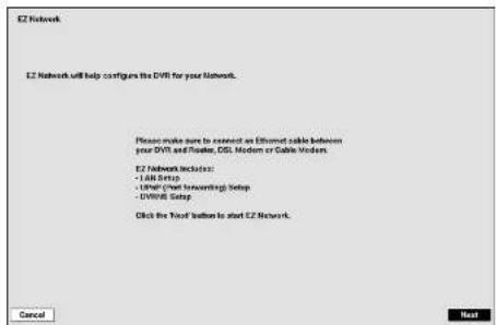
text_image
E2 Network E2 Network will help configure the EVR for your network. Please make sure to restart an Ethernet cable between your DVR and Router, DSL Medium or Cable Modens E2 Network Includes: - USB Setup - Ethernet (most forwarding) Setup - DVR/WR Setup Click the Traf button to start E2 Network. Cancel NextIf you selected the Go to EZ Network, select the Next button to start the EZ Network.
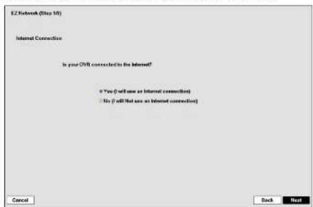
text_image
I2 Network (Step 10) Internet Connection Is your OVR connected to the Internet? Yes (I will now or Internet connection) No (I will not use as Internet connection)Internet Connection
Select whether or not your DVR is connected to the Internet.
Digital Video Recorder
LAN Setup
Select between Auto Configuration and Manual Configuration for network configuration, and then select the Test button to test the network configuration you selected.
NOTE: Selecting Auto Configuration allows the DVR to automatically obtain LAN parameters (IP address, Gateway, Subnet Mask and DNS Server address). Selecting Manual Configuration allows you to set up LAN parameters manually.
The network configuration you set should be tested by selecting Test, otherwise the Next button will cannot be selected, and you cannot move to the next step.
- Use DSL/PPPoE Setup: Selecting the box allows you to set up the DSL, network. Entering the ID and password for DSL connection is required.
text_image
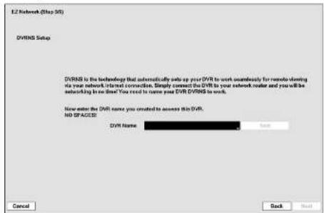
EZ Network (Step 50) DVRS Setup DVRS is the technology that automatically only up your DVR to work simultaneously for remote planning via your network internet connection. Simply connect the DVR to your network reader and you will be networking in so that. You need to name your DVR DVRS to work. Now enter the DVR name you created to access this DVR. NO SPACES? DVR Name Back Cancel Back NextDVRNS Setup
- DVR Name: Enter the DVR name to be registered on the DVRNS server.
NOTE: The DVR Name you entered should be checked by selecting Test, otherwise the DVRNS changes will not be saved.
When entering no name or a name already registered on the DVRNS server, an error message displays.

Operation Instruction
Highlight System Shutdown and press the Ⓞ button. The Shutdown screen displays asking you to confirm whether or not you want to shut the system down.
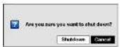
After selecting Shutdown and pressing the Ⓤ button, a screen will appear telling you when it is safe to disconnect power.
Date/Time
text_image
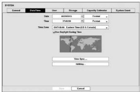
SYSTEM General Data/Time User Storage Capacity Estimator System Event Date 68/04/2013 Format Time 17:03:54 Format Time Zone GMT-06:00 Eastern Time (US & Canada) Use Daylight Saving Time Time Spot... Holiday... Save CancelFigure 9: System - Date/Time setup screen.
Highlight the first box beside Date and press the button. The individual sections of the date will highlight. Use the Up and Down arrow buttons to change the number. Use the Left and Right arrow buttons to move between month, date and year. Once you have the correct date, press the button.
Highlight the Format box beside Date and press the Ⓧ button. Select from the three available date formats and press the Ⓧ button to save your selected format.
Highlight the first box beside Time and press the ⏱ button. The individual sections of the time will highlight. Use the Up and Down arrow buttons to change the number. Use the Left and Right arrow buttons to move between hour, minutes and seconds. Once you have the correct time, press the ⏱ button.
Highlight the Format box beside Time and press the ⏻ button. Select from the three available time formats and press
Digital Video Recorder
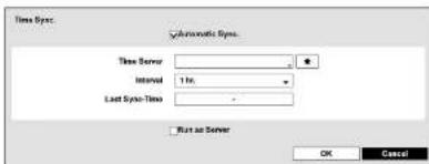
text_image
Time Sys. Automatic Sys. Time Server Internal 1 Hz Last Sys-Time Run as Server OK CancelHighlight the box beside Automatic Sync. and press the ⏻ button. This toggles between On and Off.
Highlight the box beside Time Server and press the button. A virtual keyboard appears that you can use to enter the IP address or domain name of the time server. Highlighting allows you to select your time server from a list of registered time servers.
NOTE: You can use the domain name instead of IP address if you already set up the DNS Server when setting up the LAN.
Highlight the box beside Interval and press the ⏻ button. Set the time interval for synchronization from 30 minutes to 1 day at various time intervals.
Last Sync-Time displays the last time the DVR was synchronized with the time server.
Highlight Run as Server and press the Ⓧ button. Pressing the Ⓧ button toggles between On and Off. When it is On, the DVR you are setting up will run as a time server.
Highlighting Holiday... and pressing the Ⓤ button displays the Holiday screen.
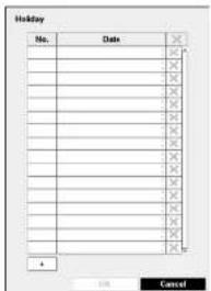
text_image
Holiday No. Date X X X X X X X X X X X X X X X X X X X X X X X X 4 OK CancelYou can set up holidays by highlighting + and pressing the ⏻ button. The current date appears.
Highlight the month and day and change them by using the Up and Down arrow buttons. Press the Ⓐ button to add the date. Dates can be deleted by highlighting the ✗ beside the date and pressing the Ⓐ button.
NOTE: Holidays that do not fall on the same date each year should be updated once the current year's holiday has passed.
Operation Instruction
User

text_image
SYSTEM General Data/Time User Storage Capacity Estimator System Event Group & User Administrator admin Group & User Auto Logic Never Auto Logot Never Save CancelFigure 10: System – User setup screen.
The +/- column is used to collapse and expand user groups. If there is a + or - in this column, it indicates the item is a Group Name. If there is a - in front of the Group Name, it indicates that the group has been "expanded" and all of the User Names within that group are displayed below the Group Name. If there is a + in front of the Group Name, it indicates that the group has been "collapsed" and all of the User Names within that group are hidden. To collapse or expand a group, highlight the +/- column in front of the desired group and press the ⊗ button.
Highlighting a Group Name and pressing the ⏻ button allows you to change the authority levels assigned to the group.
CAUTION: Write down the new password and save it in a secure place. If the password is forgotten, the unit must be reset using the Factory Reset Button and all data settings will be lost.
Highlighting a User Name and pressing the Ⓞ button allows you to add or change the password assigned to that user. You can also change the group to which the user is assigned.
The X column can be used to delete a User Name or an entire Group. If the X is grayed out, that Group or User cannot be deleted. Highlight the X and press the Ⓧ button. You will be asked to confirm that you want to delete the User or Group. To delete the User currently logged into the DVR on a local system or a PC running Speco Central II. log the user out of the system first and then delete the user.
To add a Group highlight the 1 Group how and pray that a button. A virtual backboard measure allowing you to
Digital Video Recorder

text_image
Group Authority Shutdown Upgrade Color Control System Check PTZ Control Alarm-Out Control Chest Camera View Digital Deterior Control Camera Clip Copy System Time Change Data Clear PTZ Setup Alarm-Out Setup Chest Camera Setup OK CancelHighlighting the Authority box and pressing the Ⓧ button will toggle between all authority levels being turned On and Off. Highlighting the individual authority level boxes and pressing the Ⓧ button will toggle between that authority level being turned On and Off. The authority levels that can be turned On and Off arc:
- Shutdown – The user can shut the system down on a local system.
- Upgrade – The user can upgrade the software on a local system or a PC running Speco Central II.
- Color Control – The user can control brightness, contrast, hue and saturation for cameras on a local system or a PC running Speco Central II.
- System Check – The user can view the remote system status or check the remote system status as a batch process on a PC running Speed Central II.
- PTZ Control – The user can control the PTZ camera on a local system or a PC running Speco Central II.
-
Alarm-Out Control – The user can reset the DVR's outputs including the internal buzzer during an alarm by pressing the any button on the front panel on a local system or alarm-out control button on a PC running Speco Central II.
-
Covert Camera View – The user can view video from cameras set as Covert while in the Live Monitoring or Search mode on a local system or a PC running Speco Central II.
- Digital Deterrent Control – The user can trigger the Digital Deterrent sound manually by selecting (Digital Deterrent) in the Live Monitoring menu and Search menu on a local system.
- Search – The user can access the Search mode on a local system or a PC running Speco Central II
- Clip-Copy – The user can copy video clips on a local system or a PC running Speco Central II.
- Setup – The user without Setup authority cannot establish any system settings excluding system shutdown and logout on a local system or a PC running Speco Central II.
- System Time Change – The user can change the system date and time on a local system or a PC running Speed Central II.
- Data Clear – The user can clear all video data or format disks on a local system or a PC running Speco Central I
- PTZ Setup – The user can establish all PTZ settings on a local system or a PC running Speco Central II.
- Alarm-Out Setup – The user can establish all Alarm-Out settings on a local system or a PC running Space Central II.
• Covert Camera Setup – The user can establish all Covert Camera settings on a local system or a PC running Speco Central II. - Record Setup – The user can establish all Record settings on a local system or a PC running Speco Central II.
- Setup Import – The user can import saved DVR settings from a local system or a PC running Speco Central II.
- Setup Export – The user can export the current DVR settings to a local system or a PC running Speco Central II.
- Digital Deterrent Setup – The user can establish all Digital Deterrent settings on a local system.
- VNC Setup – The user can establish all VNC settings on a local system or a PC running Speed Central II.

To add a User, highlight the +User... box and press the 📧 button. A virtual keyboard appears allowing you to enter the User Name. Enter the name and assign the User to a Group and password. You can use camera buttons on the front panel to assign the password. The password can be up to 8 digits. You will be asked to confirm the password.
Operation Instruction
Storage
text_image
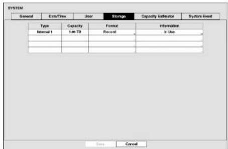
SYSTEM General Data/Time User Storage Capacity Estimator System Event Type Capacity Format Information Internal 1 1.00 TB Record In Use ... ... ... ... Save CancelFigure 11: System - Storage setup screen.
The information in the Type column describes the storage device.
The capacity of the storage device is displayed in the Capacity column.
The Format column displays whether the device is used for recording (Record) or not (Not Using). Not formatted indicates the device is not formatted.
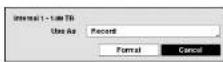
Highlight the box in the Format column for the desired storage device and press the Ⓧ button. You will be able to format the device for recording. When selecting Not Using from Use As and highlighting the Format button, the device will not be used for recording.
The Information column displays whether the device is being used or not. Other indicates the device has been used for another DVR.
Highlight the box in the Information column for the desired storage device and press the ⏻ button.
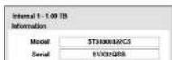
You will be able to check the model name, serial number and the time information about recorded data of the selected storage device.
If you want to erase recorded data on the selected device, highlight Clear and press
Digital Video Recorder
Capacity Estimator

text_image
SYSTEM General Data/Time User Storage Capacity Calculator System Event Video Format NTSC Quality Rasic Number of Cameras 8 Frequency Standard(CF-0004) Number of Cameras 4 Frame Rate 90.00 fps Average Event Rate N/A Dark Capacity 1000 GB Estimated Recordable Time: 22 Days and / hrs NOTE: The estimated recordable time can be different from actual recorded time. Save CancelFigure 12: System – Capacity Estimator setup screen.
The Capacity Estimator screen allows you to calculate the available record time of the DVR's storage device. Set up the calculation conditions.
• Video Format: Select the video format: NTSC or PAL.
• Number of Cameras: Select the number of cameras.
• Number of Audio-In: Select the number of audio inputs.
• Average Event Rate: Set the average event rate.
• Quality: Set the recorded image quality.
- Resolution: Set the recorded image resolution.
• Frame Rate: Set the images per second for recording.
- Disk Capacity: Set the capacity of the storage device.
Estimated Recordable Time displays the estimated available record time.
NOTE: The estimated available record time can vary from the actual recording time.
System Event

Operation Instruction
The DVR can be configured to run self-diagnostics and report the results.
Highlight the Settings box beside the desired event (System, Check Recording, Check Alarm-In, Disk Almost Full, Disk Bad, or Disk Temperature), and press the 🔒 button.
Highlight the Settings box beside System and press the Ⓞ button. You can select the interval that you want the DVR to run self-diagnostics on the system. You can select from 1 hr. to 30 days or Never.
Highlight the Settings box beside Check Recording and press the Ⓤ button. The Check Recording screen appears.
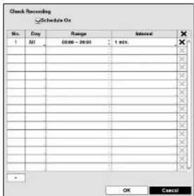
text_image
Check Recording Schedule On No. Day Range Interval 1 All 00:00 - 20:00 1 min. X X X X X X X X X X X X X X X X X X X X X X X X X OK CancelHighlighting Schedule On and pressing the 📋 button toggles On and Off. When set to On, you can select the day, time range and interval that you want the DVR to run self diagnostics on the recorder. The Interval can be selectable from 1 min, to 7 days or Never. Highlight the + and press the 🔊 button to add a schedule item. The ✗ box allows you to delete a check recording schedule.
Highlight the Settings box beside Check Alarm-In and press the Ⓞ button. You can select the interval that you want the DVR to run self-diagnostics on Alarm Inputs. You can select from 1 hr. to 30 days or Never.
Highlight the Settings box beside Disk Almost Full, and press the Ⓧ button. Select the percentage level of disk usage at which you want the DVR to trigger an alert. Percentage levels range from 80% to 99%.
Highlight the Settings box beside Disk Bad, and press the Ⓞ button. Select percentage level of bad disk sectors at which you want the DVR to trigger an alert. Percentage levels range from 10% to 90%.
Highlight the Settings box beside Disk Temperature, and press the Ⓐ button. Select the temperature of hard disk drive at which you want the DVR to trigger an alert if the temperature exceeds the defined threshold. Refer to the hard disk drive manufacturer's documentation for the correct temperature setting.
The DVR can be set to react to system events. Highlight the Actions box beside the desired event and press the Ⓧ button. System events can be associated with an Alarm-Out connector, sound the DVR's internal buzzer, and/or notify a number of different devices.
NOTE: Alarm-Out action cannot be set to System Boot Unit Restart Shutdown and Denio Record events
Digital Video Recorder
Recording Setup
General

text_image
RECORD General Schedules Pre-Event Event Record Overl 8 sec Record Audio Auto Deletion Power Limit Time-Lapse Recording Power Use Pasc Recording Pasc Recording Duration No Limit Ips 30.89 fps Quality High Resolution High(2074600H) Save CancelFigure 14: Record – General setup screen.
Highlighting Recycle and pressing the Ⓧ button toggles between On and Off. In the Recycle mode, the DVR records over the oldest video data once all available storage space has been used. When Recycle is turned off, the DVR stops recording once all available storage space has been used.
Highlight the Event Record Dwell box and set the length of time you would like to record for the associated event. You can set the dwell from 5 seconds to 30 minutes. Refer to Event Actions screen in this chapter for information regarding event recording.
The DVR can record up to four audio inputs. Highlighting Record Audio and pressing the ⏻ button toggles between On and Off.
Highlight the slide bar beside Auto Deletion, and use the Left and Right arrow buttons or Up and Down arrow buttons to adjust the length of time recorded data will be kept from 1 to 999 days. The DVR automatically deletes video recorded earlier than the user-defined period under three conditions: at midnight, whenever the system reboots or whenever the user changes the Auto Deletion settings. Selecting Never will disable the Auto Deletion function.
Highlight the slide bar beside Limit Time-Lapse Recording, and use the Left and Right arrow buttons to adjust the length of the maximum angle. The time-lapse recording from 1 to 20 days. The limit time-lapse recording
Operation Instruction
Highlighting the Panic Recording -ips and pressing the button allows you to set the images per second for Panic recording. You can select from 1.00 to 30.00 ips (25.00 ips PAL).
Highlighting the Panic Recording – Quality and pressing the Ⓐ button allows you to set the recorded image quality for Panic recording. You can select from: Very High, High, Standard and Basic.
Highlighting the Panic Recording - Resolution and pressing the ⏻ button allows you to set the recorded image resolution for Panic recording. You can select from: Very High (D1/960H), High (2CIF/H960H) and Standard (CIF/Q960H).
Schedule

text_image
ACOBER General Options Preferences ✓Select to Single Units No. 100 Range 100-200 Units 1-4 Settings OK Cancel Send Next< Simple Mode >
text_image
PC0003 General Database Preferred AutoCAD No AutoCAD Mode AutoCAD Mode AutoCAD No AutoCAD Mode AutoCAD No AutoCAD Mode AutoCAD No AutoCAD Mode AutoCAD No AutoCAD Mode AutoCAD No AutoCAD Mode AutoCAD No AutoCAD Mode AutoCAD No AutoCAD Mode AutoCAD No AutoCAD Mode AutoCAD No AutoCAD Mode AutoCAD No AutoCAD Mode AutoCAD No AutoCAD Mode AutoCAD No AutoCAD Mode AutoCAD No AutoCAD Type AutoCAD No AutoCAD Mode AutoCAD No AutoCAD Mode AutoCAD No AutoCAD Mode AutoCAD No AutoCAD Mode AutoCAD No AutoCAD Mode AutoCAD No AutoCAD Mode AutoCAD No AutoCAD Mode AutoCAD No AutoCAD Mode AutoCAD No AutoCAD Mode AutoCAD No AutoCAD Mode AutoCAD No AutoCAD Mode AutoCAD No AutoCAD Mode AutoCAD NO AutoCAD Mode AutoCAD No AutoCAD Mode AutoCAD No AutoCAD Mode AutoCAD No AutoCAD Mode AutoCAD No AutoCAD Mode AutoCAD No AutoCAD Mode AutoCAD No AutoCAD Mode AutoCAD No AutoCAD Mode AutoCAD No AutoCAD Mode AutoCAD No AutoCAD Mode AutoCAD No AutoCAD Mode AutoCAD No AutoCAD Mode AutoCAD No AutoCAD Use Save Cancel< Advanced Mode >
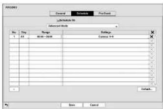
Figure 15: Record – Schedule setup screen.
You can program the DVR to record only during certain times based on time, day of the week, and holidays. The smallest time segment you can use is 15 minutes.
Highlighting Schedule On and pressing the Ⓐ button toggles between On and Off. In the Schedule On mode, the DVR records video based on the schedule established in the Schedule screen. When turning Schedule recording Off, you will be asked to confirm your decision, and Ⓤ displays at the top-left corner of each camera screen. Panic recording will function even when Schedule is turned off. 🌐 displays during panic recording.
Highlight the Schedule Mode box and press the Ⓞ button. You can select between Simple Mode and Advanced Mode. Selecting Advanced Mode allows you to set up individual recording schedule for each event.
NOTE: Changing the schedule mode will reset all event and action statuses.
Highlight the + and press the ⏻ button to add a schedule item.
Digital Video Recorder
When the DVR is in the Event mode, the red 🔊 icon displays at the top-left corner of the screen. The DVR will record and displays the 🔊 icon at the top-left corner of the screen when any event occurs. When the DVR is in the Pre-Event recoding mode, the yellow 🔊 icon displays when there is no event, and the DVR is not recording. When the DVR is in the Pre-Event mode, the red 🔊 and display when any event occurs and the DVR starts recoding.
When the DVR is in the Time & Event mode, the DVR will follow the Time settings and the icon displays at the top-left corner of the screen. The DVR follows the Event settings and the icon displays.
Highlight the box under the Channels heading and press the Ⓐ button to select which cameras will be recorded. (Simple Mode Only)
Highlight the box under the Settings heading and press the ⏻ button to define the recording settings.
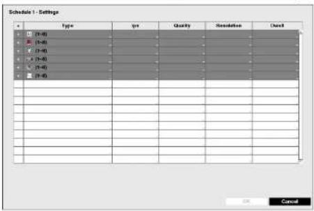
Figure 16: Schedule – Settings (Advanced Mode) setup screen.
You can set the ips, Quality and Resolution (ips, Quality, Resolution and Dwell for Advanced Mode setup) of the recording for any modes you set up in the Mode column. If you do not set the ips, Quality, Resolution and Dwell in the Settings column, the DVR will follow the default settings. See below for details.
NOTE: Descriptions of the Record icons in the Type column are as follows:
Time-lapse (Time) Alarm-In Motion
Video Loss Video Blind Text-In
Channels that are not defined will use the setting values of the previous schedule item.
When multiple events are detected at the same time from a specific channel, the DVR will record event
video with the high setting values if the info. Quality Resolution and Dual volume of events are different
Operation Instruction
Highlighting boxes under Quality and pressing the Ⓧ button allows you to set the recorded image quality for Time and Event recording. You can select from: Very High, High, Standard and Basic.
Highlighting boxes under Resolution and pressing the Ⓞ button allows you to set the recorded image resolution for Time and Event recording. You can select from: Very High (D1/960H), High (2CIF/H960H) and Standard (CIF/Q960H).
Highlighting boxes under Dwell and pressing the ⏻ button allows you to set the length of time you would like to record for the associated event. (Advanced Mode Only)
Pre-Event

text_image
RECORD General Schedule Pre Event Rec Irs Quality Resolution Devl ✓1 30.00 fps Standard Standard(CF/QMSH) 00 min. 00 sec. ✓2 30.00 fps Standard Standard(CF/QMSH) 00 min. 00 sec. ✓3 30.00 fps Standard Standard(CF/QMSH) 00 min. 00 sec. ✓4 30.00 fps Standard Standard(CF/QMSH) 00 min. 00 sec. ✓5 30.00 fps Standard Standard(CF/QMSH) 00 min. 00 sec. ✓6 30.00 fps Standard Standard(CF/QMSH) 00 min. 00 sec. ✓7 30.00 fps Standard Standard(CF/QMSH) 00 min. 00 sec. ✓8 30.00 fps Standard Standard(CF/QMSH) 00 min. 00 sec. Score CancelFigure 17: Record – Pre-Event setup screen.
When the DVR is in the Event Record mode it is possible to have it record images before the event occurs. The Pre-Event screen allows you to define how to handle pre-event recording. If you do not have Event set up in the Record Schedule, a message will display alerting you to this fact.
You can turn individual cameras On or Off for pre-event recording. The image speed can be set from 1.00 to 30.00 ips (25.00 ips PAL), image quality can be selectable from Very High, High, Standard and Basic, and image resolution can be selectable from Very High (D1/960H), High (2CIF/H960H) and Standard (CIF/Q960H).
You can set the amount of time to record prior to the event by adjusting the Dwell. You can set the Dwell from 5 seconds to 30 minutes. The longer the dwell set, the fewer maximum ips can be set.
NOTE: When the DVD is in the Time or Time 0 Event mode, it ignores the pre-event settings and follows the
Digital Video Recorder
Event Setup
Motion
text_image
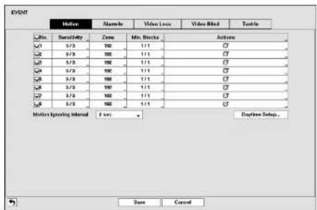
EVENT Motion Balance Video Loss Video Blind Tools No. Sensitivity Zone Min. Blocks Action ✓1 3/3 102 1/1 ✓2 3/3 102 1/1 ✓3 3/3 102 1/1 ✓4 3/3 102 1/1 ✓5 3/3 102 1/1 ✓6 3/3 102 1/1 ✓7 3/3 102 1/1 ✓8 3/3 102 1/1 Motion Islanding Interval: 2 sec Daytime Setup. Save CancelFigure 18: Event - Motion setup screen.
Your DVR has built-in video motion detection. Video motion detection can be turned On or Off for each camera.
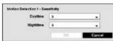
Highlighting the box under the Sensitivity heading and pressing the Ⓧ button allows you to adjust the DVR's sensitivity to motion for Daytime and Nighttime independently. There are five settings with 1 being the least sensitive and 5 being the most sensitive.
You can define the area of the image where you want to detect motion; e.g., a doorway. Highlight the box under the Zone heading, and press the ⏻ button. The Motion Zone screen displays.

The Motion Zone screen is laid over the video for the selected camera. You can set up motion zones by selecting or clearing blocks.
NOTE: You can set up motion zones one block at a time in groups of four or eight individual block groups (4- and 8-channel DVR respectively). A block group is positioned within the image area using the Up and Down arrow buttons, and individual blocks within the block groups are selected or cleared using the camera buttons
Operation Instruction

You can adjust the minimum number of detection blocks that must be activated to trigger a motion alarm. Highlighting the box under the Min. Blocks heading and pressing the Ⓧ button allows you to adjust the minimum number of detection blocks for Daytime and Nighttime independently. Smaller numbers provide greater sensitivity because fewer detection blocks must be activated.
Highlight the box under the Actions and press the Ⓧ button. The DVR can be set to react to motion differently for each camera. Each camera can be associated with another camera, trigger an Alarm-Out connector, sound the DVR's internal buzzer, notify a number of different devices, move PTZ cameras to preset positions, and/or sound.
You can control excessive event logging and remote notification of motions detected after the motion dwell time by adjusting the motion ignoring dwell intervals. Highlight the box beside Motion Ignoring Interval and press the button. A list of intervals ranging from 1 to 10 seconds or Never appears. The DVR will not log and notify motion events occurred during the preset interval range.
NOTE: The record action for motion events will not be affected by the Motion Ignoring function.
Highlighting Daytime Setup and pressing the Ⓧ button allows you to set up the Daytime range.
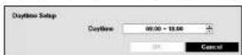
Highlight the box beside Daytime and press the Ⓧ button. Use the Up and Down arrow buttons to set the Daytime range. The DVR will consider the remaining time range as the Nighttime.
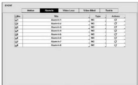
Alarm-In
text_image
EXOM Hellen Alarm-In Video Locus Video Blind Tools Title Type Actions x1 Alarm-In 1 NC ☑ x2 Alarm-In 2 NC ☑ x3 Alarm-In 3 NC ☑ x4 Alarm-In 4 NC ☑ x5 Alarm-In 5 NC ☑ x6 Alarm-In 6 NC ☑ x7 Alarm-In 7 NC ☑ x8 Alarm-In 8 NC ☑Digital Video Recorder
Video Loss
text_image
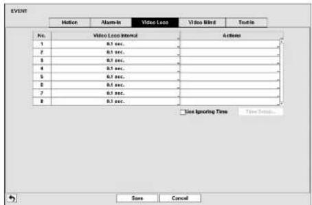
EVENT Motion Alarm-In Video Load Video Blind Tools-In No. Video Load Interval Actions 1 0.1 sec. 2 0.1 sec. 3 0.1 sec. 4 0.1 sec. 5 0.1 sec. 6 0.1 sec. 7 0.1 sec. 8 0.1 sec. □ Use Ignoring Time Time Settings... Save CancelFigure 20: Event – Video Loss setup screen.
Highlighting the box under the Video Loss Interval heading allows you to set the duration of a signal loss before the DVR will report a Video Loss. The DVR will not consider any signal loss from a camera to be a Video Loss if the detected signal loss is shorter than the interval set on this screen.
Highlight the box under the Actions and press the Ⓜ button. The DVR can be set to react to video loss differently for each camera. Each camera can be associated with another camera, trigger an Alarm-Out connector, sound the DVR's internal buzzer, notify a number of different devices, and/or move PTZ cameras to preset positions.
Highlight Use Ignoring Time and press the Ⓧ button to toggle between On and Off. When set to On, the DVR will ignore video loss events occurring during the preset period. Highlighting Time Setup and pressing the Ⓧ button allows you to set up event ignoring time.
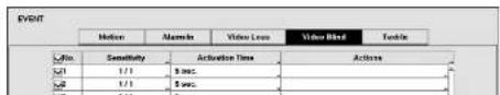
Video Blind
text_image
EVENT Motion Acceleration Video Loss Video Blind Toticle Sensitivity Activation Time Actions 1/1 5 sec. 2/2 5 sec. 1/3 5 sec.Operation Instruction
The DVR checks to see if anything is blinding a camera.
Highlighting the box under the Sensitivity heading allows you to adjust the DVR's sensitivity to video blind for Black and White independently from 0 (Never) and 1 (least sensitive) to 15 (most sensitive).
NOTE: Video blind might NOT be detected for a camera with a very noisy image especially when set for low sensitivity values.
Highlighting the box under the Activation Time heading allows you to set the duration before the DVR will report a Video Blind. The DVR will not consider any blinded camera to be a Video Blind if the detected blindness is less than the Activation Time set on this screen.
Highlight the box under the Actions and press the Ⓧ button. The DVR can be set to react to video blind differently for each camera. Each camera can be associated with another camera, trigger an Alarm-Out connector, sound the DVR's internal buzzer, notify a number of different devices, and/or move PTZ cameras to preset positions.
Highlight Use Ignoring Time and press the Ⓧ button to toggle between On and Off. When set to On, the DVR will ignore video blind events occurred during the preset period. Highlighting Time Setup and press the Ⓧ button allows you to set up event ignoring time.
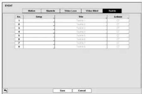
Text-In
text_image
EVENT Motion Alarm-In Video Loss Video Blind Table No. 1 2 3 4 5 6 7 8 Save CancelFigure 22: Event - Text-In setup screen.
The DVR can be set to react to text input from devices such as ATMs (Automated Teller Machines) and POS (Point
Digital Video Recorder

text_image
Tools 1 Port: 00002 Setup... Tools Product: Generic Text Transaction Start Any Character Transaction End 3 rows (in) Line Collector Ignore String None Corrective Time Out 10 sec. 00 sec. OK CancelHighlight the box beside Port, and press the ⏻ button. Select from None, RS232, RS485, USB-Serial (1\~8) and LAN (1\~8).
NOTE: If you have set the Port as None, you will not be able to make any changes to the screen.
When using the USB to serial text-in device, do NOT remove the USB cable from the port while the system is running.
Highlight Setup.... and press the Ⓞ button. Use the ATM or POS manufacturer's recommended settings when configuring the RS232, RS485, USB-Serial or LAN ports.
Highlight the box beside Text-In Product, and press the ⏻ button. Select your device from the list.
NOTE: The following description is for a Generic Text Device. The screen changes for different types of text input devices, and there will be different parameter boxes for you to enter information.
Highlight the box beside Transaction Start, and press the Ⓞ button. Use the virtual keyboard to enter the Transaction Start string. Refer to the device manufacturer's documentation for the text string that the device first sends when a transaction starts.
If you want the DVR to react to any character sent from the text input device, you will want to turn On Any Character. Highlight Any Character, and press the ⏻ button to toggle between On and Off.
NOTE: If Any Character is turned On, you will not be able to enter any text in the Transaction Start box.
Highlight the box beside Transaction End, and press the Ⓧbutton. Use the virtual keyboard to enter the Transaction End string. Refer to the device manufacturer's documentation for the text string that the device sends when a transaction ends.
Highlight the more line(s) box, and press the ⏻ button. Select the number of additional lines of text that you want the DVR to record. You can choose from 0 to 10.
Operation Instruction
Each input can be given a title. Highlight the desired Title box and press the Ⓧ button. A virtual keyboard appears allowing you to enter a title name.
Highlight the box under the Actions and press the button. The DVR can be set to react to text input. Text input can be associated with cameras, trigger an Alarm-Out connector, sound the DVR's internal buzzer, notify a number of different devices, and/or move PTZ cameras to preset positions.
Camera Setup
General

text_image
CAMERA General PT2 No. Title Use Mode ✓ CAMF Normal 800 ✓ CAMB Normal 800 ✓ CAMC Normal 800 ✓ CAMD Normal 800 ✓ CAME Normal 800 ✓ CAMF Normal 800 ✓ CAMG Normal 800 ✓ CAMH Normal 800 ✓ CAMI Normal 800 ✓ CAMJ Normal 800 ✓ CAMK Normal 800 ✓ CAML Normal 800 ✓ CAMM Normal 800 ✓ CAMN Normal 800 ✓ CAMO Normal 800 ✓ CAMP Normal 800 ✓ CAMQ Normal 800 ✓ CAMR Normal 800 ✓ CAMS Normal 800 ✓ CAMN Normal 800 ✓ CAMO Normal 800 ✓ CAMP Normal 800 ✓ CAMQ Normal 800 ✓ CAMQ Normal 800 ✓ CAMR Normal 800 ✓ CAMM Normal 800 ✓ CAMN Normal 800 ✓ CAMO Normal 800 ✓ CAMP Normal 800 ✓ CAMQ Normal 800 ✓ CAMQ Normal 800 ✓ CAMR Normal 800 ✓ CAMM Normal 800 ✓ CAMN Normal 800 ✓ CAMO Normal 800 ✓ CAMP Normal 800 ✓ CAMQ Normal 800 ✓ CAMQ Normal 800 ✓ CAMR Normal 800 ✓ CAMM Normal 800 ✓ CAMN Normal 800 ✓ CAMO Normal 800 ✓ CAMP Normal 800 ✓ CAMQ Normal 800 ✓ CAMQ Normal 800 ✓ CAMR Normal 800 ✓ CAMM Normal 800 ✓ CAMN Normal 800 ✓ CAMO Normal 800 ✓ CAMP Normal 800 ✓ CAMQ Normal 800 ✓ CAMQ Normal 800 ✓ CAMR Normal 800 ✓ CAMM Normal 800 ✓ CAMN Normal 800 ✓ CAMO Normal 800 ✓ CAMP Normal 800 ✓ CAMQ Normal 800 ✓ CAMQ Normal ✓ CAMR Normal 800 ✓ CAMM Normal 800 ✓ CAMN Normal 800 ✓ CAMO Normal 800 ✓ CAMP Normal 800 ✓ CAMQ Normal 800 ✓ CAMQ Normal 800 ✓ CAMR Normal 800 ✓ CAMM Normal 800Figure 23: Camera - General setup screen.
You can turn the camera number On or Off, and you can change the Title of each camera using the virtual keyboard. You can also determine which cameras will display on the monitors by selecting Normal, Covert 1 or Covert 2 from a drop-down list in the Use column.
NOTE: When selecting the Covert 1, the DVR displays the camera title and status icons on the covert video. When selecting the Covert 2, the DVR displays only camera title on the covert video. A user who does not have Covert Camera View authority cannot view video from cameras set to Covert 1 or Covert 2 in both the live monitoring and playback modes.
Digital Video Recorder
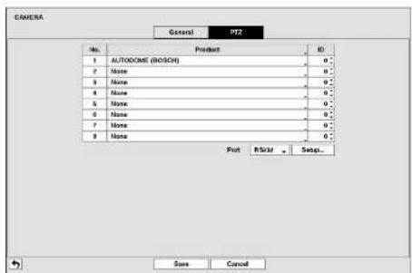
PTZ
text_image
CAMERA General F12 No. Product ID 1 AUTOCOME (ROSCH) 0° 2 None 0° 3 None 0° 4 None 0° 5 None 0° 6 None 0° 7 None 0° 8 None 0° Put RsKit Sepa... Save CancelFigure 24: Camera – PTZ setup screen.
NOTE: You will only be able to set up PTZ devices if the PTZ port is set to RS232 or RS485.

text_image
Nose LUCOSIN (A0591) C-COOH (O4) CDC26 (C6orf) CD3496 (Dysaclo) CRS-RABR (Chlmmur) CFR-180a (Fex) CRS-1401 (PAX1855E) Synthecine(Pyrin) Desulfide(Desulf) DM1723 (Tefan) DH560 (Exergene Unblyc) Drosophila (Drosoph) Dialysis (Dialysis) (Desaromatic) Turkine (Turk) Turband (Turb) Tubulin B (Tubulin) G1 subunit Acetyl-CoA (TrpBp) GRAPAR 5.5 (Hspexpyl) HDL-695 (Hspexpyl) HDL-202 (HDL-Hspexpyl) HDL-2021 (Hspexpyl) B0160 (B016) Kilin (Kilin) Tyr Pyrin (Tyrp)Highlight the box in the Product column for the PTZ camera you wish to configure and press the button. A list of PTZ devices appears. Select your camera from the list and press the button. You will need to connect the camera to the RS232 or RS485 connector on the back of the DVR following the camera manufacturer's instructions.
You can assign IDs to each camera by highlighting the box under the ID heading and pressing the ⏻ button. Change the
Operation Instruction
Device Setup
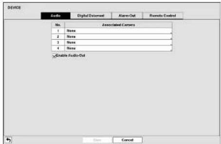
Audio
text_image
DEVICE Audio Digital Environment Alarm-Out Remote Control No. Associated Camera 1 None 2 None 3 None 4 None Enable Audio-Out Save CancelFigure 25: Device – Audio setup screen.
The DVR can record up to four audio inputs. Highlight the box beside the input and press the ⏻ button. A list of cameras appears, and you can select which camera you want associated with that audio input.
Highlight Enable Audio-Out and press the ⏻ button. This toggles between enabling and disabling audio out.
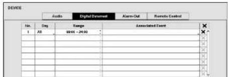
Digital Deterrent
text_image
DEVICE Audio Digital Document Alarm-Out Remote Control No. 1 Day Range Associated Event 02/04 - 26:30 × × × × × × × × × × × × × × × × × × × × × × × × × × × × × × × × × × × × × × × × × × × × × × × × × × XDigital Video Recorder
Highlight the box under the Range heading and press the ⏻ button to change the time range that the scheduled digital deterrent will take place. The smallest time segment you can use is 15 minutes.
Highlight the box under the Associated Event heading and press the ⓧ button to select which events you want associated with each digital deterrent.
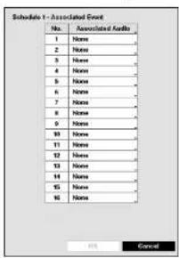
text_image
Schedule 1 - Associated Event No. Associated Events 1 Name 2 Name 3 Name 4 Name 5 Name 6 Name 7 Name 8 Name 9 Name 10 Name 11 Name 12 Name 13 Name 14 Name 15 Name 16 Name OK CancelYou can select the audio files associate with each event. Highlight the box under the Associated Audio and press the button. A list of audio file name appears, and you can select which audio file you want to associated with that event.

You can import saved audio files or export the current audio files. To import saved audio files, connect the USB device containing the audio file (aaf or .wav) to the DVR. Highlight Digital Dotorent - Import... and press the Ⓐ button. Select the desired audio file and press the Import button to import the selected audio file and change the audio file accordingly.
NOTE: File format has to be mono PCM 16KHz/16bit sampling.
The file names have to be "Sound_1.wav" \~ "Sound_16.wav" or "Sound_1.aaf" \~ "Sound_16.aaf" for
USB import. (USB has to be in FAT32)
The files have to be in the top folder of the USB flash drive.
The file name format is case insensitive.
If the audio file in .wave format, it will be converted to .aaf file in 10 seconds when imported.
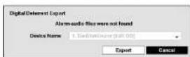
To export the current audio files, connect the USB device to the DVR. Highlight Digital Deterrent - Export... and press the Ⓧ button. Highlight the box beside File name and press the Ⓧ button. A virtual keyboard allows you to enter the file name. Selecting Export will save the current audio file in .self file format on the USB device.
Operation Instruction
Highlight the box beside To and press the button to toggle between On and Off. When set to Off, you can enter a specific Date and Time. When set to On, the search will be to the last recorded audio. When highlighting ▼ and pressing the button the bookmark list displays and the bookmark point you selected will be the ending date and time.
Highlight the box beside File name and press the Ⓧ button to select the file name. The selected audio file can be listened by highlighting ⏻ and pressing the Ⓧ button.
Once you have selected the file name, highlight the Start button and press the ⏻ button to record the extracted audio file (up to 10 seconds).
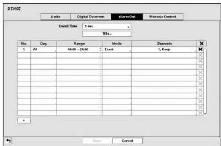
Alarm-Out
text_image
DEVICE Audio Digital Document Alarm-Out Remote Control Dwell Time 5 sec... Title... File: Day Range Mode Channels 1 AB 80.00 - 26.00 Event 1, Beep X X X X X X X X X X X X X X X X X X X X X X X X X X X X X X X X X X X X X X X X X X X X X X X X X X Y CancelFigure 27: Device – Alarm-Out setup screen.
Highlighting the box beside Dwell Time and pressing the Ⓞ button allows you to set the dwell time of the alarm output. Dwell times range from 5 seconds to 30 minutes.
Each alarm output can be given its own title by highlighting Title... and pressing the Ⓧ button. A virtual keyboard appears allowing you to cater the title.
You can add and edit alarm output schedules on this screen. Highlight the + and press the ⏻ button to add a schedule. Highlighting the boxes under the Column heading and pressing the ⏻ button allows you to edit the information in those boxes.
图 1.2.1 1
Digital Video Recorder
Remote Control
text_image
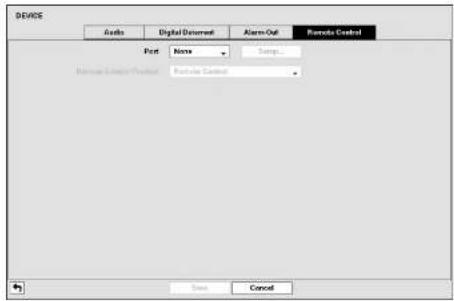
DEASE Assets Digital Document Alarm-Out Remote Control Port None Setup... Remove Calendar Provider Remote Control OK CancelFigure 28: Device - Remote Control setup screen.
Highlight the box beside Port and select from None, RS232 and RS485. If the RS232 port and RS485 port are in use for PTZ control, networking or text input, the remote keyboard cannot be configured.
Highlight Setup... and select the correct Band Rate, Parity, Data Bits and Stop Bits for the device you are connecting to the DVR.
Highlight the box beside Remote Control Product and select the device from the list.
Network Setup
General
text_image
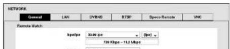
NETWORK General LAN OVRNS RTSP Speco Remote VNC Remote Watch 8spebps 30.00 fps 20pc 750 Kbps - 11.2 MbpsOperation Instruction
Highlight the first box beside Remote Watch - bps/ips. You can select the Transfer Speed from 50Kbps to 1Gbps. Highlight the second box beside Remote Watch - bps/ips. You can select the unit of measure for the transfer speed between: bps and ips. Press the Ⓧ button to set the transfer speed.
Highlight the box beside Remote Watch – Quality and press the ⏻ button. You can select the Quality from: Very High, High, Standard and Basic. Press the ⏻ button to set the Quality.
Highlight the box beside Remote Watch – Resolution and press the ⏻ button. You can select the Resolution from: Very High, High and Standard. Press the ⏻ button to set the Resolution.
NOTE: The higher Quality and Resolution settings require higher Transfer Speed settings. The transfer speed you set is the maximum speed. Depending on the network environment, this speed may not be achieved.
You can limit the network bandwidth settings so that the system does not consume too much network bandwidth. Highlight the box beside Network Bandwidth Limit and press the Up and Down arrow buttons to set the desired maximum bandwidth from 100Kbps to 1Gbps.
NOTE: When limiting the network bandwidth, the remote watch image on the PC running Speco Central II or Speco Remote might not be displayed properly.
The DVR supports two-way audio communication between a local system and a PC running Speco Central II. Highlighting the box beside Remote Audio Channel and pressing the ⏻ button allows you to select the audio channel that sends audio to the remote site. Selecting Select From Speco Central will send audio of the channel selected from Speco Central II.
NOTE: Depending on network conditions, audio might be interrupted or out of synchronization during transmission.
Highlight Enable SSL for Transferring Data and press the button to toggle between On and Off. When it is On, the security of data except video and audio transmitted for remote monitoring or remote recording can be enhanced by using the SSL (Secure Sockets Layer) authentication. When using the SSL function, the DVR cannot be connected with a remote program or a network keyboard which does not support the SSL function.
CAUTION: The remote connection will be disconnected temporarily after changing the SSL settings.
NOTE: While the SSL function is enabled, the network transfer speed you selected may not be achieved. This product includes software developed by the OpenSSL Project for use in the OpenSSL Toolkit (http://www.openssl.org/).
LAN

Digital Video Recorder
Highlight the box beside Type and press the ⏻button. You can select the type of network configuration from: Manual, DHCP and ADSL (with PPPoE). Select the desired type and press the ⏻button.
Selecting Manual from the Type allows you to set up LAN parameters manually.
Change the numbers by highlighting them and using the Up and Down arrow buttons to increase or decrease the number. The factory default LAN settings are:
IP Address: 192.168.1.129
Gateway: 192.168.1.254
Subnet Mask: 255.255.255.0
NOTE: You will need to get the appropriate IP Address, Gateway and Subnet Mask from your network administrator.
Highlight the box beside DNS Server. Press the Up and Down arrow buttons to set the IP address of the DNS server.
Highlight the Port Number Setup... box and press the ⏻ button. The Port Number Setup screen appears.
NOTE: You will need to get the appropriate Port Numbers for each Speco Central II and Speco Remote related program (Admin, Callback, Watch and Search) from your network administrator.

Change the numbers by highlighting them and using the Up and Down arrow buttons to increase or decrease the number. The factory default Port settings are:
Remote Admin: 8200
Remote Callback: 8205
Remote Watch: 8201
Remote Search: 8202
NOTE: The system restarts automatically after changing the port settings.
Do NOT use the same port number for two different programs, otherwise, the DVR cannot be connected with the PC running Speco Central II or Speco Remote.
CAUTION: When changing the port settings, you must change the port settings on the PC running Speco Central II as well. Refer to the Speco Central II manual for details.
Highlight Use UPnP and press the button to toggle between On and Off. When it is On, port forwarding from the NAT (Network Address Translation) device to the DVR will be enabled automatically via UPnP (Universal Plug and Play) service. This function will be especially useful when accessing a port on a private IP address.
NOTE: For the UPnP service to work, the NAT device should support the UPnP Port Forwarding function and the function should be set to enabled.
You cannot change the port settings when Use UPnP is On.
Highlight the Status box and press the Ⓤ button to display the port numbers forwarded from the NAT device via UPnP
Operation Instruction
Selecting DHCP from the Type and highlighting Save button reads the current IP address of the DVR configured by DHCP (Dynamic Host Configuration Protocol) network.
Highlight Auto (Default) and press the ⏻ button to toggle between On and Off. When it is On, the DVR will obtain the IP address of the DNS server automatically.
NOTE: Selecting Auto will only be enabled when the DVR is configured for DHCP or an ADSL network.
Selecting ADSL (with PPPoE) allows you to set up the ADSL network.
Highlight the box beside ID and press the Ⓧ button. A virtual keyboard appears allowing you to enter the ID for ADSL connection.
Highlight the box beside Password and press the ⏻ button. A virtual keyboard appears allowing you to enter the password for ADSL connection.
NOTE: Entering the ID and Password and highlighting OK reads the current IP address of the DVR configured by the ADSL network.
If the DVR is configured for DHCP or an ADSL network, the IP address of the DVR might change whenever the unit is turned on.
DVRNS

text_image
NETWORK General LAN DVRNS RTSP Space Remote VMC Use DVRN Name Service DVRNS Server: dsm.spcsctech.net Port 10000 (1996 - 12000) DVRN Name Check Status Save CancelFigure 31: Network – DVRNS setup screen.
Digital Video Recorder
NOTE: The DVR Name you entered should be checked by selecting Check, otherwise the DVRNS changes will not be saved.
When entering no name or a name already registered on the DVRNS server, an error message displays.
The box beside Status displays the current information of the Rendezvous server and NAT (Network Address Translation) device.
RTSP

text_image
NETWORK General LAN OVRNS RTSP Space Remote VNC Enable RTSP RTSP Port 384 (396 - 68820) RTSP Port RTSP Start Port 10001 (1006 - 65008) RTSP End Port 17000 Use Module Size CancelFigure 32: Network - RTSP setup screen.
Highlight Enable RTSP (Real-Time Streaming Protocol) and press the Ⓐ button to toggle between On and Off. You will be able to change the settings if Enable RTSP is enabled.
Highlight the box beside RTSP Port and press the ⏻ button. Set the port number of the RTSP server obtained from your system administrator.
Highlight the box beside RTP Start Port and press the ⏻ button. Set the start port number of the RTP server obtained from your system administrator.
Highlight the box beside RTP End Port and press the ⏻ button. Set the end port number of the RTP server obtained from your system administrator.
Highlight Use Mobile and press the Ⓤ button to toggle between On and Off. When set to on, you can access a remote (Will write 10 seconds or other mobile buttons)
Operation Instruction
Speco Remote

text_image
NETWORK General LAN OVRNS RTSP Speed Remote VMC Auto Space Remote Service Port 0244 (1334 - 8803) Save CancelFigure 33: Network – Space Remote setup screen.
Highlight Use Speco Remote Service and press the ⓧ button to toggle between On and Off. See Appendix – Speco Remote for detailed descriptions of the Speco Remote service.
Highlight the box beside Port and press the ⏻ button. Set the port number used when accessing Speco Remote by using the Up and Down arrow buttons to increase or decrease the numbers.
VNC
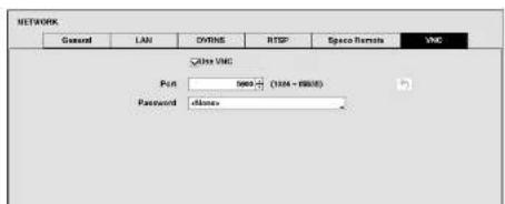
text_image
NETWORK General LAN OTRINS RTSP Space Remote VNC Other VNC Port 5000 (1004 - 8800) Password :clonesDigital Video Recorder
Highlight the box beside Password and press the ⏻ button. A virtual keyboard appears allowing you to enter the password for VNC connection.
NOTE: Up to three users at a time can access a DVR remotely via VNC service.
When controlling the DVR remotely using a keyboard, shortcut keys perform the following functions as described below:
| Key Function | |
| “+” or “h” | Pressing the “←” or “h” key moves to the left in the menu. It is the same as pressing the Left arrow button on the front panel. |
| • +” or “l” | Pressing the “→” or “l” key moves to the right in the menu. It is the same as pressing the Right arrow buttons on the front panel. |
| “↑” or “k” | Pressing the “+” or “k” key moves up in the menu. It is the same as pressing the Up arrow button on the front panel. |
| •↓” or “j” | Pressing the “↓” or “j” key moves down in the menu. It is the same as pressing the Down arrow button on the front panel. |
| “m” or “■” (Windows) | Pressing the “m” or “■” key displays the Live Monitoring menu or Search menu on the screen. It is the same as pressing the [MENU] button on the front panel. |
| “Enter” or “Return” | Pressing the “Enter” or “Return” key selects the highlighted item or completes an entry that you have made during system setup. It is the same as pressing the ©Play/Pause) button on the front panel. |
| “d” or “PageUp” or “PageDown” | Pressing the “d” or “PageUp” or “PageDown” key toggles between different display formats. |
| “c” or “Home” | Pressing the “c” or “Home” key allows you to copy video clips. It is the same as pressing the COPY button on the front panel. |
| “F5” Pressing the “F5” key refreshes the current VNC screen. | |
Notification Setup
Callback
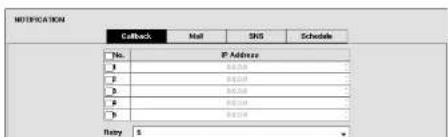
text_image
NOTIFICATION CnBack Mail SMS Schedule No. IP Address B 012349 B 012349 B 012349 B 012349 Rlty: 5Operation Instruction
Highlight the IP Address box that you want to change and press the ⏻ button. Use the arrow buttons to enter the IP address of the computer you want contacted during an event. You can enter up to five IP addresses.
Highlight the box beside Retry and enter the number of times you would like the DVR to try contacting the computer. You can select from 1 to 10 retries.
Mail
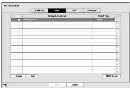
text_image
NOTIFICATION Group & Recipient Attach Type default group Name Group & Recipient Group & Recipient Group & Recipient Group & Recipient Group & Recipient Group & Recipient Group & Recipient Group & Recipient Group & Recipient Group & Recipient Group & Recipient Group & Recipient Group & Recipient Group & Recipient Group & Recipient Group & Recipient Group & Recipient Group & Recipient Group & Recipient Group & Recipient Group & Rec Premier Group & Rec Premier Group & Rec Premier Group & Rec Premier Group & Rec Premier Group & Rec Premier Group & Rec Premier Group & Rec Premier Group & Rec Premier Group & Rec Premier Group & Rec Premier Group & Rec Premier Group & Rec Premier Group & Rec Premier Group & Rec Premier Group & Rec Premier Group & Rec Premier Group & Rec Premier Group & Rec Premier Group & Rec Premier Group & Rec President Group & Rec President Group & Rec President Group & Rec President Group & Rec President Group & Rec President Group & Rec President Group & Rec President Group & Rec President Group & Rec President Group & Rec President Group & Rec President Group & Rec President Group & Rec President Group & Rec President Group & Rec President Group & Rec President Group & Rec President Group & Rec President Group & Rec President Group & Rec Director Group & Rec Director Group & Rec Director Group & Rec Director Group & Rec Director Group & Rec Director Group & Rec Director Group & Rec Director Group & Rec Director Group & Rec Director Group & Rec Director Group & Rec Director Group & Rec Director Group & Rec Director Group & Rec Director Group & Rec Director Group & Rec Director Group & Rec Director Group & Rec Director Group & Rec Director Group & Rec DirectorsFigure 36: Notification - Mail setup screen.
The DVR can be set up to send an email when an event occurs. The Mail Group and Recipient can be turned On or Off by highlighting the boxes beside the individual mail group and recipient accounts and pressing the ⏻ button. Highlighting the box beside "Group & Recipient" and pressing the ⏻ button will toggle between all mail accounts being turned On and Off.
The +/- column is used to collapse and expand recipient groups. If there is a + or - in this column, it indicates the item is a Group Name. If there is a - in front of the Group Name, it indicates that the group has been "expanded" and all of the Recipient Names within that group are displayed below the Group Name. If there is a + in front of the Group Name, it indicates that the group has been "collapsed" and all of the Recipient Names within that group are hidden. To collapse or expand a group, highlight the +/- column in front of the desired group and press the Ⓞ button.
The X column can be used to delete a Recipient Name or an entire Group. If the X is grayed out, that Group or Recipient cannot be deleted. Highlight the X and press the ⏻ button. You will be asked to confirm that you want to delete the Recipient or Group.
Digital Video Recorder

text_image
Recipient Group default group Display Name Address OK CancelHighlight Use and press the Ⓧ button to toggle between On and Off. Assign the Recipient to a Group and enter the Recipient's Display Name.
Highlight the box beside Address and enter the recipient's e-mail address and mail server provider. Highlighting allows you to select the mail server provider from a list of registered SMTP mail server providers.
Highlight the box under the Attach Type heading and press the Ⓧ button to change the image file format attached to an email.
NOTE: Attaching a Image file to an email will not be available for the Text-in event.
Highlight SMTP Setup... and press the ⏻ button. The SMTP Setup screen appears.
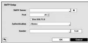
text_image
SMTP Setup SMTP Server Port 25 Max SIR/TLB AuthenticationHighlight the box beside SMTP Server and press the Ⓧ button. A virtual keyboard appears that you can use to enter the IP address or domain name of the SMTP server. Highlighting ⚠ allows you to select your SMTP server from a list of registered SMTP servers.
NOTE: You will need to get the IP Address or domain name of the SMTP Server from your network administrator.
NOTE: You can use the domain name instead of IP address. If you already set up the DNS Server when setting up the LAN.
Highlight the box beside Port and press the ⏻ button. Use the arrow buttons to enter the SMTP Server port number obtained from your system administrator. The default port number is 25.
Highlight Use SSL/TLS and press the ⏻ button to toggle between On and Off. When it is On, the DVR can send an email via an SMTP server requiring SSL (Secure Sockets Layer) authentication.
NOTE: This product includes software developed by the OpenSSL Project for use in the OpenSSL Toolkit (http://www.openssl.org/).
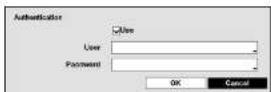
Highlight the box beside Authentication and press the 📊 button. An Authentication screen appears. Highlight Use and press the ⚙ button to toggle between On and Off. Highlight the box beside User/Password and press the ⚙ button. A virtual keyboard appears allowing you to enter the user ID and password.
Highlight the box beside Sender and enter the sender's e-mail address. Use the virtual keyboard to enter the e-mail address.
Operation Instruction
SNS

text_image
NOTIFICATION Callback Mail SMS Schedule SNS + + + + + + + + + + + + + + + + + + + + + + + + + + + + + + + + + + + + + + + + + + + + + + + + + + + + - Back CancelFigure 37: Notification – SNS setup screen.
The DVR can be set up to post a message via SNS (Social Network Service) when an event occurs. You can add and edit the SNS account on this screen. The SNS account can be turned On or Off by highlighting the boxes under the No. heading and pressing the ⏻ button.
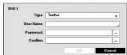
To add an SNS account, highlight the + and press the Ⓧ button. Highlight the box beside Type and press the Ⓧ button. Selecting Twitter from the Type allows you to post a tweet on Twitter when an event occurs.
Highlight the box beside User Name/Password and press the ⏻ button. A virtual keyboard appears allowing you to enter the user name and password.
The SNS accounts can be deleted by highlighting the ✗ beside the account and pressing the ⏻ button.
NOTE: Posting a tweet might fail because of Twitter limitations.
Schedule

Digital Video Recorder
You can add and edit notification schedules on this screen. Highlight the + and press the ⏻ button to add a schedule. Highlighting the boxes under the Column heading and pressing the ⏻ button allows you to edit the information in those boxes.
The Day box allows you to select the days that the notification schedule will be active. The choices are: Sun, Mon, Tue, Wed. Thu, Fri. Sat, M\~F, Hol and All.
The Range box allows you to set the time that the notification schedule will be active in 15-minute increments from 00:00 to 24:00.
Highlight the desired box under the Notify heading, and press the ⏻ button. The Schedule Notify menu appears.

text_image
Schedule 1 - Notification Notification MIL1 (1) LAN 1: Range LAN 2: Range LAN 3: Range LAN 4: Range LAN 5: Range LAN 6: Range Summary (1): OK CancelYou can toggle the entire list On and Off by highlighting Notification and pressing the ⏻ button. You can toggle the individual items On and Off by highlighting that item and pressing the ⏻ button. Highlight OK and press the ⏻ button to accept your changes.
NOTE: For the Notify action, the notify item you select should be enabled in the Notification setup screen and the DVR should be registered in the Speco Central II (Remote Administration System).
NOTE: The Notify action for system events you made in the System Event setup screen on the System menu will not be affected by your Notification Schedule settings.
Highlight the box beside Summary Email Interval and select the interval that you want the DVR to send a summary email. The DVR will send an email containing a summary of events detected during the preset interval.
Display Setup
OSD
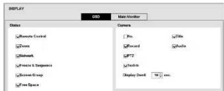
text_image
DISPLAY Status ✓ Remote Control ✓ Focus ✓ Network ✓ Freeze & Segurança ✓ Screen Group ✓ Free Space Main Monitor Camera ✓ Pro. ✓ Title ✓ Record ✓ Audio ✓ PTZ ✓ Touch-in Display Dash: 10 sec.Operation Instruction
- Freeze & Sequence – The icon ✕ displays while in the Freeze mode, and the □ displays while in the Sequence mode.
- Screen Group – The number of screen group displays when the DVR is not in the 3x3 and 1P7 display modes of the 8-channel DVR, and 2x2 mode of the 4-channel DVR.
- Free Space – The icon 📋 displays when the DVR is in the Recycle mode, and the percentage of available storage space displays when the DVR is not in the Recycle mode.
- Date/Time – The current date and time information displays.
- User Name – The name of the current user logged in displays.
- Background Panel – The background panel at the bottom of the screen displays in black.
- Camera No. – The camera number displays at the top-left corner of each camera screen.
- Camera Title – The camera title displays at the top-left corner of each camera screen.
- Record – The record related icons display on each camera screen.
- Audio - The iom displays on each camera screen for which the DVR can play live audio.
- PTZ - The icon displays on each PTZ camera screen.
- Text-In – The text input strings display on the screen. You can adjust the Display Dwell time (sec.) for the text input strings displayed on the screen.
You can adjust the transparency of the setup screens by highlighting Transparency and using the Left and Right arrow buttons.
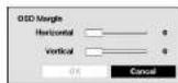
Highlighting OSD Margin... and pressing the Ⓐ button displays how OSD text will be displayed on the monitor. You can adjust the horizontal and vertical margins so that text and icons will not be hidden beyond the edges of the monitor.
Main Monitor
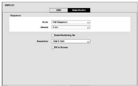
text_image
DISPLAY GSD Main Monitor Sequence Mode Full Sequence Internal 3 sec Event Monitoring On Resolution 1200 X 1224 Fill To ScreenDigital Video Recorder
NOTE: Sequence cannot be used in the 3x3 and 1P7 modes of the 8-channel DVR, and 2x2 mode of the 4-channel DVR.
You can adjust the display dwell time by highlighting the box beside Interval and pressing the Ⓤ button. You can select dwell intervals ranging from 1 second to 1 minute.
Highlight Event Monitoring On and press the Ⓧ button. Pressing the Ⓧ button toggles between On and Off. When it is On, the DVR will display the camera associated with the event when an event occurs.
Highlight the box beside Resolution and press the button. You can select from 1280x1024, 1440x900 and 1920x1080 for NTSC video, and 1280x1024, 1440x900 and 1920x1080 (@ 60Hz or 50Hz) for PAL video.
NOTE: When the Individual main monitors are connected to the HDMI and VGA connectors for simultaneous operation, it is recommended to use monitors supported with the same resolution. If monitors unsupported with the same resolution are connected, video cannot be displayed on the monitor with the resolution you have set.
Highlight Fit To Screen and press the Ⓧ button. Pressing the Ⓧ button toggles between On and Off. When it is On, the DVR will resize video to fit the main monitor screen.
Operation Instruction
Digital Video Recorder
Chapter 4 — Operation
NOTE: This chapter assumes your DVR has been installed and configured. If it has not, please refer to Chapters 2 and 3.
The DVR's controls are similar to a VCR. As with a VCR, the main functions are recording and playing back video. However, you have much greater control over recording and playing back video. You can establish recording schedules based on time of day and day of the week. The DVR allows you to search through the recorded video using much more sophisticated tools than those available with VCRs. Additional DVR features that are not available with VCRs are remote control and viewing, and recording video at the same time you are watching previously recorded video.
The front panel controls are described in Chapter 3 — Configuration.
Turning on the Power
Once you have installed the DVR following the instructions in Chapter 2 — Installation, it is ready to record.
Live Monitoring
As soon as the DVR completes its initialization process, it will begin showing live video on the attached monitor and playing live audio through the attached speaker. The default mode is to display all cameras at once. Pressing any camera button will cause that camera to display full screen. It displays live video and plays live audio until the user enters another mode.
While in the live monitoring mode, pressing the MENU button displays the following Live Monitoring menu on the right edge of the screen. Pressing the FSC button hides the menu. You can navigate through menus and items by pressing the arrow buttons.
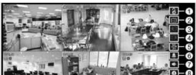
natural_image
Interior view of a modern office or lab space with multiple workstations and desks (no visible text or signage)① Login/Logout
② Display
③ Previous Group
④ Next Group
⑤ Freeze
Alarm
② Digital Deterrent
Operation Instruction
Live Monitoring Menu
Login/Logout
Selecting 8 (Login) in the Live Monitoring menu accesses the Login screen, and you will be asked to select a User and enter the password to log into the system. Selecting 6 (Logout) in the Live Monitoring menu displays the Logout screen asking you to confirm whether or not you want to log out the current user.
Display
- Full Screen: Selecting (Display) → (Full Screen) and choosing the camera number button displays the selected camera full screen. It is the same as pressing the individual camera buttons on the front panel or clicking the left mouse button on a camera image when in one of the multiview formats (i.e., 2x2, 1P5, 1P7 or 3x3). Clicking the left mouse button on the screen again returns to the previous display mode.
- PIP, 2x2, 1P5, 1P7, 3x3: Selecting (Display) → or (PIP, 2x2, 1P5, 1P7 or 3x3) displays the cameras in the selected multiview screen mode (PIP, 2x2, 1P5, 1P7 or 3x3). Selecting each display mode is the same as scrolling the mouse wheel up and down when in one of the multiview formats (i.e., 2x2, 1P5, 1P7 or 3x3).
NOTE: In the 1P5 or 1P7 display mode, the main channel indicates the channel displayed on the large screen which is displayed in the top-left. You can select the camera you want to display on the main channel screen. Select a channel on the screen and click the right mouse button to display the Camera Menu. Selecting Go To Main swaps the selected channel with the main channel. This function is supported only in the 1P5 and 1P7 display modes and can be activated from any of channel screens except the main channel screen.
- Camera OSD, Status OSD: Selecting (Display) → Camera OSD or Status OSD toggles Camera OSD or Status OSD On and Off.
Previous Group, Next Group
Selecting ☐ or ☑ (Previous Group or Next Group) in the Live Monitoring menu moves to the previous or next page.
Freeze
Selecting 🎨 (Freeze) in the Live Monitoring menu will freeze the current image on the screen until you select 🎨 again. It is the same as pressing the Ⓧ(Play/Pause) button. Pressing any button except for the MENU button while in the Freeze mode can also exit the Freeze mode. While in the Freeze mode, the icon 🎨 displays in bottom-left corner if Freeze is selected in the Display setup screen (OSI tab).
Alarm
Paloating (A) is the Line Monitoring room meets the 1992's concrete included in the internal human device on a cloud
Digital Video Recorder
Sequence
Selecting (Sequence) in the Live Monitoring menu causes the cameras to display sequentially. When in one of the multi-view formats, selecting will cause the DVR to go through predefined screen layouts (Full Sequence). Or, the bottom, right screen will display live cameras sequentially (Cameo Sequence). For example, if you select in the 2x2 format, the DVR changes pages as follows:
< Full Sequence >
< Cameo Sequence >
Selecting 📄 again in the Live Monitoring menu exits the Sequence mode. While in the Sequence mode, the 📄 icon displays in bottom-left corner if Sequence is selected in the Display setup screen (OSD tab). If all the cameras in a page are Off, or have lost video or are set to Covert (unless the user has authority to view covert cameras), that page will be excluded from the sequence.
NOTE: The Full Sequence for the full sequence monitoring and the Cameo Sequence for the cameo sequence monitoring should be selected in the Display setup screen (Main Monitor tab).
Camera Menu
- PTZ: Selecting (Camera Menu) → PTZ and choosing the camera number allows you to control the selected camera as long as it has Pan, Tilt and Zoom capabilities. Refer to the following PTZ Mode section for details.
- Zoom: Selecting (Camera Menu) → Zoom and choosing the camera number zooms the current image of the selected camera on the screen. Selecting Zoom again in the Camera Menu again exits the Zoom mode. Refer to the following Zoom Mode section for details.
• Audio: Selecting 📄 (Camera Menu) → Audio toggles audio output On and Off.
- Color Control: Selecting (Camera Menu) → Color Control and choosing the camera number allows you to control brightness, contrast, hue and saturation for each camera for the selected camera if a user who has Color Control authority logs into the system. It is the same as pressing and holding a camera button for a few seconds.
- Edit Group: Selecting ☐ (Camera Menu) → Edit Group enters to the Active Cameo mode. Refer to the following Active Cameo Mode section for details.
NOTE: It is important that cameras and monitors are correctly installed and adjusted prior to making any image adjustments using the DVR's controls.
Any image adjustments you make will be applied to both the live video on the monitors and the recorded video.
The Camera Menu also can be displayed by clicking the right mouse button on the screen while in the live monitoring mode.
Search
Operation Instruction
Active Cameo Mode
You can enter the Active Cameo mode by selecting (Display) → Edit Group in the Live Monitoring menu in any multi-view format. The yellow outline surrounding the video indicates the active cameo, and pressing the arrow buttons moves the active cameo. Pressing the (Play/Pause) button exits the Active Cameo mode. Selecting Exit Group Edit in the cameo mode displayed when pressing the [MENU] button also exits the Active Cameo mode. The active cameo mode will remain in effect for 15 seconds if there is no further operation.
In active cameo mode, press the button for the camera you want to display in the active cameo. After setting the camera number to active cameo, the DVR moves the active cameo to the next cameo. When the camera number exists on the current screen, the active cameo is changed with the existing camera number. When the camera number does not exist on the current screen, the active cameo is replaced by the camera number. You can change the screen layout in this way.
Zoom Mode
You can enlarge an area of the video by selecting 📄 (Camera Menu) → Zoom in the Live Monitoring menu. For a few seconds after selecting 📄 → Zoom, a rectangle displays on the screen. A rectangle shows the area that will be enlarged. You can move the rectangle around using the arrow buttons. Pressing the Ⓧ (Play/Pause) button in the Zoom mode enlarges the area in rectangle. Exit the Zoom mode by selecting 📄 (Exit) in the Zoom menu displayed when pressing the ⏚Menu button. While in the Zoom mode, the icon Ⓧ displays if Zoom is selected in the Display setup screen (OSD tab).
PTZ Mode
If a user who has PTZ Control authority logs into the system, the user can control PTZ cameras. The DVR will control cameras with Pan, Tilt and Zoom capabilities. Select (Camera Menu) → PTZ in the Live Monitoring menu to display the PTZ camera menu and enter the PTZ mode. Selecting (Exit) in the PTZ menu displayed when pressing the MENU button exits the PTZ mode.
Select the PTZ camera you wish to control by selecting it from the menu. The icon P displays on the PTZ camera screen.
To use the remote control buttons, press the Left and Right arrow buttons to pan left and right. Press the Up and Down arrow buttons to tilt the camera up and down. Press the ZOOM + button to zoom in, and press the ZOOM - button to zoom out. You can use the FOCUS and FOCUS buttons to focus the image.
You can establish preset positions for PTZ cameras. Press the PRESET SET button to establish Presets.
You can quickly move PTZ cameras to Preset positions. Press the PRESET SELECT button to view an established camera Preset position.
Digital Video Recorder
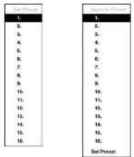
You can save camera position settings as "presets" so that you can go directly to desired views.
Once you have the camera at the desired settings, press the the PRESET SET button, and the Set Preset dialog box will appear. Select the number you want to assign to the preset and press the ⏻ (Play/Pause) button. Use the virtual keyboard to enter the preset name.
Press the PRESET SELECT button to load the PTZ preset and the Move to Preset dialog box will appear. Select the desired preset and press the ⏻ button to load the preset.
Figure 43: PTZ Preset menu.

While in the PTZ mode, pressing the MENU button and selecting 🔒 (Advanced PTZ) in the menu displaying at the top of the screen displays the Advanced PTZ menu.
Set the feature you wish to control by selecting it from the menu. Refer to the camera manufacturer's instructions for the proper settings. Depending on the camera specifications, some features may not be supported.
NOTE: The Pan/Tilt speed can be controlled by using the mouse. While in the PTZ mode, clicking the left mouse button on the image and dragging the mouse in the pan/tilt direction you want to move and then select the speed.
You can use a mouse for convenient PTZ control. Click the left mouse button on the image and move that image in the direction you want to by dragging the mouse. Use the mouse wheel to zoom in and out. Position the mouse pointer at the bottom of the screen, and the following PTZ toolbar will display.
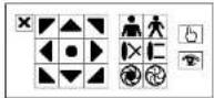
Clicking ✗ on the left side exits the toolbar. If you want to display the toolbar again, position the mouse pointer at the bottom of the screen. Change the toolbar location by clicking the empty space on the left side of the toolbar and drag it to where you want it located on the screen. Use the arrow buttons on the toolbar to pan or tilt the camera in the direction you want. The other controls on the toolbar perform as described below:
Zoom In / Out Focus Near Iris Open / Close Set / Load Projet
Operation Instruction
Covert Camera
If a camera is set up as Covert 1 in the Camera setup screen (General tab), that camera will not be displayed unless a user with Covert Camera View authority logs into the system. However the camera title and status icons will be displayed on the monitor.
If a camera is set up as Covert 2 in the Camera setup screen (General tab), that camera appears to be Off unless a user with Covert Camera View authority logs into the system. The camera title will be grayed out and status icons will not be displayed on the monitor.
NOTE: When a camera is set up as Covert 1, the DVR displays the camera title and status icons on the covert video. When set up as Covert 2, the DVR displays only the camera title on the covert video.
If a user who has Covert Camera View authority logs into the system, the user can view video from cameras set to Covert 1 or Covert 2 including the camera titles and status icons.
Status Monitoring
Selecting ☑ (Status) in the Live Monitoring menu or Search menu displays the Event Status screen.

text_image
Event Status Event Status Storage 1 2 3 4 5 6 7 8 1 2 3 4 5 6 7 8 1 2 3 4 5 6 7 8 1 2 3 4 5 6 7 8 1 2 3 4 5 6 7 8 Public Record Short Duration Full Check Recording Short Full Fan Error Disk Config Change CloseFigure 44: Event Status – Event Status screen.
The Event Status screen displays the status of the DVR's systems and inputs. Events will be highlighted, and related
Digital Video Recorder
Highlighting the Storage tab will display the hard disk drive status.

text_image
Event Status Event Status Storage Type Cisk Bed Temperature SMAA.T. Internal 1 Good (5%) Good (30°F) Good Over Over Over Over Over Over CloseFigure 45: Event Status – Storage screen.
The Type column displays the type of storage device.
The Disk Bad column displays the percentage of bad sectors. Not formatted indicates the device is not formatted.
The Temperature column displays the temperature of the storage device.
The S.M.A.R.T. column displays "Good", "Bad" or "N/A", depending on storage conditions.
• Good – The storage condition is normal.
- Bad – Data cannot be written on or read from the storage device.
- N/A – Storage conditions are normal, however, the S.M.A.R.T. monitoring is not working or supported.
NOTE: When the storage condition is "Bad", the Event Status – Storage screen displays and you can check the storage condition for details. Once the "Bad" message displays, replacing the hard disk drive is recommended, usually within 24 hours.
Temperature and S.M.A.R.T. Information will be available only for Internal hard disk drives supporting the SMART (Self-Monitoring Analysis and Reporting Technology) monitoring program.
Recording Video
According to the IMU following the introduction in Class 2, a second structure was added. The IMU
Operation Instruction
NOTE: When the DVR is not in the Recycle mode and all available storage space has been used, panic recording will not operate.
Recording Audio
If the DVR was set up to record audio, it will record audio from up to four inputs when video is recording.
NOTE: Make certain you comply with all local and federal laws and regulations when recording audio.
Playing Recorded Video
If a user who has Search authority logs into the system, the user can view recorded image. Once video has been recorded, you can view it by pressing the PLAY/STOP button.
The DVR supports the Triplex function: monitoring, recording and playing back at the same time. Pressing the PLAY/STOP button when in one of the multi-view formats enters the Triplex mode and displays the Select Playback Camera menu.
| All Channels |
| 1. CMA1 |
| 2. CMA2 |
| 3. CMA3 |
| 4. CMA4 |
| 5. CMA5 |
| 6. CMA6 |
| 7. CMA7 |
| 8. CMA8 |
Selecting All Channels plays back video of all cameras. The DVR maintains the same display format as it does in the live mode except for the PIP format. You can also change the screen layout in the same way as you do in the live mode.
Selecting the camera number under Triplex enters the Triplex mode and plays back video of the selected camera. When in the single-screen display format, the camera currently displayed on the screen will be selected and when in the PIP display format, the camera displayed on the PIP screen will be selected for the search channel. During the Triplex mode, the DVR maintains the same display format as it does in the live mode. A red outline surrounding the video and the camera title indicates the search channel. While in the Triplex Mode, the DVR continues recording cameras as they were set up in the recording schedule. Also, live monitoring will continue except for the camera that has been selected for playback.
Figure 46: Select Playback Camera menu.
When playing video for the first time, the DVR will display the most recent image. When playing video subsequent times, the DVR will start playing video from the last recalled image. Recorded audio will be played when the DVR displays a camera with recorded audio in full screen mode.
NOTE: Only the administrator and users with Covert Camera View authority can view video from covert cameras. The covert cameras in the playback mode are determined by the current camera settings.
Camera Buttons: Pressing the individual camera buttons will cause the selected camera to display full screen, and
Digital Video Recorder
You can use a mouse for convenient playback control. Position the mouse pointer on the playback screen, and the following Record Table Search (Compact View Mode) screen will display. The individual controls on the toolbar perform the following functions as described below:
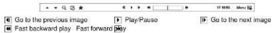
Searching Video
While in the search mode, pressing the MENU button displays the following Search menu on the right edge of the screen. Pressing the ESC button hides the menu. You can navigate through menus and items by pressing the arrow buttons.
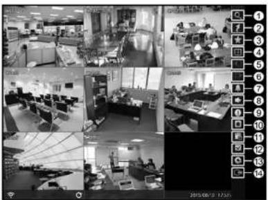
text_image
Black-and-white collage of an office interior with multiple workstations, computer monitors, and numbered security camera panels on the right.① Search
② Go To
③ Bookmark
④ Display
⑤ Previous Group
Next Group
① Alarm
⑧ Digital Deterrent
⑨ Panic
Camera Menu
⑪ Export
⑫ Status
Data Source
④ Exit
Figure 47: Search menu.
NOTE: The Search menu also can be displayed by moving the mouse pointer on the right edge of the screen.
Search Menu
Search
Operation Instruction

Move the cursor over the date and time and press the Play/Pause button. You can use the Left and Right arrow buttons to highlight the year, month, day, hours, minutes and seconds. Use the Up and Down arrow buttons to change to the date and time you want to search for video.
Once you have set the date and time you want, press the Ⓧ button. Then highlight Go and press the Ⓧ button. The selected date and time will display. (If no video was recorded during the selected time, a message appears alerting you that no image was recorded at that time.) The Ⓧ button and arrow buttons can now be used to review the surrounding video.
Bookmark
Selecting ☐ (Bookmark) in the Search menu adds the current playback point to the bookmark list. See the following Bookmarks section for details.
Display
- Full Screen: Selecting (Display) → (Full Screen) and choosing the camera number button displays the selected camera full screen. It is the same as pressing the individual camera buttons on the front panel or clicking the left mouse button on a camera image when in one of the multiview formats (i.e., 2x2, 1P5, 1P7 or 3x3). Clicking the left mouse button on the screen again returns to the previous display mode.
- 2x2, 1P5, 1P7, 3x3: Selecting (Display) → 📄, 📄, or (2x2, 1P5, 1P7 or 3x3) displays the cameras in the selected multiview screen mode (2x2, 1P5, 1P7 or 3x3). Selecting each display mode is the same as scrolling the mouse wheel up and down when in one of the multiview formats (i.e., 2x2, 1P5, 1P7 or 3x3).
- Camera OSD, Status OSD: Selecting (Display) → Camera OSD or Status OSD toggles Camera OSD or Status OSD On and Off.
Previous Group, Next Group
Selecting ☐ or ☑ (Previous Group or Next Group) in the Search menu moves to the previous or next page.
Alarm
Selecting ▲ (Alarm) in the Search menu resets the DVR's outputs including the internal buzzer during an alarm. It is the same as pressing any button on the front panel when the alarm is activated.
Digital Deterrent
Selecting (Digital Deterrent) in the Search menu displays the following setup screen and allows the DVR to play manually.
Normal Digital Retainer
Highlight the box beside Source name and press the Ⓧ button to select the source
Digital Video Recorder
- Edit Group: Selecting 📋 (Camera Menu) → Edit Group enters to the Active Cameo mode. Refer to the previous Live Monitoring – Active Cameo Mode section for details.
NOTE: The Camera Menu also can be displayed by clicking the right mouse button on the screen while in the search mode.
Export
- EZ Copy: Selecting 📄 (Export) → EZ Copy will set the starting point of the video to be clip copied, and the icon displays at the bottom-left corner of the screen. Selecting EZ Copy again will set the ending point of the video to be clip copied and displays the Clip-Comp screen. See the following Clip Copy section for details.
- Clip-Copy: Select (Export) → Clip-Copy, and the Clip-Copy screen appears to allow clip copy setup. See the following Clip Copy section for details.
- Print: Selecting (Export) → Print allows you to print a selected image. See the following Print section for details.
- Digital Deterrent Recording: Selecting (Export) → Digital Deterrent Recording allows you to extract audio files from recorded audio on the DVR. Refer to Chapter 3 – Configuration – Digital Deterrent section for details.
Status
Selecting (Status) in the Search menu allows you to check the status of the DVR's system, inputs and storage. Refer to the previous Live Monitoring – Status Monitoring section for details.
NOTE: Selecting Status will only be enabled for a user who has System Check authority.
Data Source
Selecting (Data Source) in the Search menu allows you to select the data source to be searched. Selecting Record searches recorded data on primary storage installed in the DVR, and selecting Other searches recorded data on storage used for another DVR then installed in this DVR.
Exit
Selecting ☐ (Exit) in the Search menu exits the search mode and enters the live monitoring mode.
Event Log Search
| Event Log Search | ||
| Time | Type | Title |
| 08/25/2013 08:10:00 | Motion 8 | CJ46 |
| 08/25/2013 08:10:00 | Motion 7 | CJ47 |
Operation Instruction
The DVR maintains a log of each time the Alarm Input port is activated. The Event Log Search screen displays this list. Use the arrow buttons to highlight the event for which you would like to see video.
There is no determined user authority to display the Event Log Search screen, however, the event video will not be played unless a user with Search authority logs into the system.
Pressing the Ⓧ (Play/Pause) button will extract the event video and display the first image of the event. Pressing the Ⓧ button will start playing the "event" video segment. Pressing PLAY/STOP returns to live monitoring.
NOTE: It is possible that no recorded image displays on the current screen. Select (Display) → Screen in the Live Monitoring menu and choose the 3x3 (8-channel DVR) or 2x2 (4-channel DVR) screen mode. You will be able to easily see the camera have recorded video during target time.
You can also narrow your event search by selecting the Option... button and setting up the new search condition.
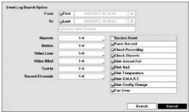
text_image
Event Log Search Options Files First To Last System Event Pass Record Check Recording Check Minutes Video Loss Video Blind Text In Record Channels 1-0 1-0 1-0 1-0 1-0 1-0 1-0 1-0 1-0 1-0 1-0 1-0 1-0 1-0 1-0 1-0 1-0 1-0 1-0 1-0 1-0 1-0 1-0 1-0 1-0 1-1 1-1 1-1 1-1 1-1 1-1 1-1 1-1 1-1 1-1 1-1 1-1 1-1 1-1 1-1 1-1 1-1 1-1 1-1 1-1 Search CancelYou can search video from the first to last recorded images, or you can set the start and stop times and dates.
Highlight the box beside From and press the button to toggle between On and Off. When set to Off, you can enter a specific Date and Time. When set to On, the search will be from the first recorded image. When highlighting! and pressing the button the bookmark list displays and the bookmark point you selected will be the starting date and time.
Highlight the box beside To and press the button to toggle between On and Off. When set to Off, you can enter a specific Date and Time. When set to On, the search will be from the last recorded image. When highlighting! and pressing the button the bookmark list displays and the bookmark point you selected will be the ending date and time.
Highlight the box beside Check Time Overlap and press the button. It toggles between On and Off. You will only be able to turn the Check Time Overlap on or off if a user-defined date and time is set to From and To. If the DVR's date and time have been reset, it is possible for the DVR to have more than one overlapping start and stop time. When set to On, you will be asked to select one of the overlapping start and stop time. When set to Off, the DVR will display search results from all start times to all stop times.
Digital Video Recorder
You can also toggle On and Off self-diagnostic System Events as part of your search. The choices are:
- Panic Record
- Check Recording
- Check Alarm-1
- Disk Almost Full
- Disk Bad
- Disk Temperature
- Disk S.M.
- Exp. Error
- Disk Config Change
Once you set your desired search conditions, highlight Search and press the Ⓞ button to display the search results in the Event Log Search screen. Selecting Cancel exits the screen without saving the changes.
Record Table Search

text_image
< Compact View > 1-4 2026/2013 04 02 05 04 05 06 07 08 08:19:41 < Standard View > 01 02 03 04 05 06 07 08 C: CAMI C: CASE C: CASED C: CASM C: CASEB C: CASEM C: CASEN C: CASEO C: CASEP C: CASEQ C: CASER C: CASES C: CASET C: CASEU C: CASEV C: CASEW C: CASEX C: CASEY C: CASEZ C: CASEA C: CASEB C: CASED C: CASEE C: CASEF C: CASEG C: CASEH C: CASEI C: CASEJ C: CASEK C: CASEL C: CASEM C: CASEN C: CASEO C: CASEP C: CASEY C: CASEZ C: CASEA C: CASEB C: CASED C: CASEE C: CASEF C: CASEG C: CASEH C: CASEI C: CASEV C: CASED C: CASEO C: CASEP C: CASEY C: CASEZ C: CASEA C: CASEB C: CASED C: CASEE C: CASEF C: CASEG C: CASEH C: CASEI C: CASEV C: CASED C: CASEO C: CASEP C: CASEY C: CASEZ C: CASEA C: CASEA C: CASEB C: CASED C: CASEE C: CASEF C: CASEG C: CASEH C: CASEI C: CASEV C: CASED C: CASEO C: CASEP C: CASEY C: CASEZ C: CASEA C: CASEA C: CASEB C: CASED C: CASEE C: CASEI C: CASEB C: CASED C: CASEO C: CASEP C: CASEY C: CASEZ C: CASEA C: CASEA C: CASEB C: CASED C: CASEE C: CASEF C: CASEG C: CASEH C: CASEI C: CASEV C: CASED C: CASEO C: CASEP C: CASEY C: CASEIFigure 49: Record Table Search screen.
Recording information about video images currently displayed on the screen displays on the recording status bar. A grey vertical line indicates the current search position. To search specific video, move the vertical line by using the Left or Right arrow buttons on the front panel or by clicking the mouse on the desired segment.
Operation Instruction
NOTE: If the DVR has images recorded in more than one recording mode in the same time range, the recording status bar displays recording information in the following priority order: Panic → Pre-Event → Event → Time. The color of the bar indicates different recording modes: Red for Panic, Yellow for Pre-Event, Purple for Event, and Blue for Time.
Selecting 16 located at the bottom displays the Calendar Search screen.
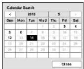
Days with recorded video display on the calendar with white numbers. You can highlight the days with recorded video by using the arrow buttons. Once you have highlighted a day, press the Play/Pause button to select it. The first recorded image of the selected date will pause on the screen. Once you have selected the date you want to search, review the surrounding video by using the playback controls located at the bottom of the Record Table Search screen.
Selecting ★ located at the bottom displays the Bookmarks screen. See the following Bookmarks section for details. The individual playback controls at the bottom perform the following functions as described below:
Go to the previous image Play/Pause Go to the next image Fast backward play Fast forward play
Selecting in the top-right corner displays the Search menu.

- Go To: Displays the first or last recorded image, or searches by date and time (see the previous Searching Video – Go To section of this chapter for more details).
- Clip-Copy: Clips a video segment and saves it (see the following Clip Copy section for more details).
• Print: Prints the current playback image. - Digital Deterrent Record: Extracts audio files from recorded audio on the DVR see Chapter 3 – Configuration – Digital Deterrent section for more details).
- Zoom: Zooms the current playback image.
- Slow Play: Plays video at low speed (x1/2, x1/3, x1/4, x1/6 and x1/8).
Selecting X in the top-left corner exits the Record Table Search screen.
Motion Search
| Motion Search | ||
| 1. CASH No. | Time | |
Digital Video Recorder
The Motion Search... can be selected from the Search menu while the DVR displays the camera full screen. The Motion Search screen displays a list of motion events. Use the arrow buttons to highlight the event for which you would like to see video and press the Ⓗ(Play/Pause) button to display the video associated with the selected event on the small search screen.
Highlighting Close and pressing the Ⓤ button will extract the video associated with the Motion event and display the first image of the event. Pressing the Ⓧ button will start playing the "event" video segment. Pressing PLAY/STOP returns to live monitoring.
You can also narrow your event search by selecting the Option... button and setting up the new search condition.

text_image
Motion Search Options Price To Type Zone Sensitivity Min. Blocks First Last Motion Search 100 Block(s)... 1 Search CancelYou can search video from the first to last recorded images, or you can set the start and stop times and dates.
Highlight the box beside From and press the button to toggle between On and Off. When set to Off, you can enter a specific Date and Time. When set to On, the search will be from the first recorded image. When highlighting! and pressing the button the bookmark list displays and the bookmark point you selected will be the starting date and time.
Highlight the box beside To and press the button to toggle between On and Off. When set to Off, you can enter a specific Date and Time. When set to On, the search will be from the last recorded image. When highlighting! and pressing the button the bookmark list displays and the bookmark point you selected will be the ending date and time.
Highlight the box beside Type and press the button. You can select between Motion Search and Museum Search. Motion Search detects motion in the defined area. Museum Search detects if a defined object has moved.
Highlight the box beside Zone and press the button. An image from the video appears with a grid overlaid. You can turn sensor blocks On and Off to define the area of the picture in which you want to search for motion.
NOTE: Defining the area of the image in which you want to search for motion is nearly identical to setting up the DVR for Motion. Please refer to Motion Screen in Chapter 3 — Configuration for more detailed instructions on setting up the detection blocks.
When setting the Museum Search Zone, the zone should be placed inside of the border line of the target object. If the selected block is placed on the border line, the sensitivity of the Museum Search may decrease.
The zone should be placed or focused on the centre or, at least, within the outline of targeted object.
Highlight the box beside Sensitivity and press the ⏻ button. You will be able to select from 1 (low sensitivity) to 5 (high sensitivity).
Operation Instruction
Text-In Search
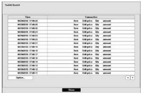
text_image
Time Transaction 00292013 17:40:25 Item Unit price Qty amount 00292013 17:40:26 Item Unit price Qty amount 00292013 17:40:29 Item Unit price Qty amount 00292013 17:40:24 Item Unit price Qty amount 00292013 17:40:23 Item Unit price Qty amount 00292013 17:40:22 Item Unit price Qty amount 00292013 17:40:21 Item Unit price Qty amount 00292013 17:40:19 Item Unit price Qty amount 00292013 17:40:18 Item Unit price Qty amount 00292013 17:40:17 Item Unit price Qty amount 00292013 17:40:16 Item Unit price Qty amount 00292013 17:40:14 Item Unit price Qty amount 00292013 17:40:13 Item Unit price Qty amount 00292013 17:40:12 Item Unit price Qty amount 00292013 17:40:11 Item Unit price Qty amount Options... CloseFigure 51: Text-In Search screen.
The DVR maintains a log of each time there is Text Input. The Text-In Search screen displays this list. Use the arrow buttons to highlight the event for which you would like to see video.
Pressing the Ⓧ (Play/Pause) button will extract the video associated with the Text Input and display the first image of the event. Pressing the Ⓧ button will start playing the "event" video segment. Pressing PLAY/STOP returns to live monitoring.
NOTE: It is possible that no recorded image displays on the current screen. Select 📊 (Display) → Screen in the Live Monitoring menu and choose the 3x3 (8-channel DVR) or 2x2 (4-channel DVR) screen mode. You will be able to easily see the camera have recorded video during target time.
Text Input information will be overlaid on the image while the recorded video is played at regular speed.
You can also narrow your event search by selecting the Option... button and setting up the new search condition.

text_image
Tools in Search Option From: Post: 0025013 002714 To: Link: 0025013 002714 Channel: 1-8 Generic Text No. - Name Comp Value Culture LineHighlight the box beside To and press the button to toggle between On and Off. When set to Off, you can enter a specific Date and Time. When set to On, the search will be from the last recorded image. When highlighting ▼ and pressing the button the bookmark list displays and the bookmark point you selected will be the ending date and time.
Highlight the Channel and press the Ⓧ button. Select the text-in devices that you want to search for text input.
Highlight the Text Input Device box and press the Ⓧ button. Select your Text Input Device from the list.
Highlighting the + and pressing the Ⓧ button allows you to add a new set of search parameter. Set up the desired search parameter. Refer to the Appendix - Text-In Search Examples for further information on setting up search parameters. The ✗ column can be used to delete a set of search parameter or entire sets of search parameters.
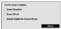
Highlighting the Option... box and pressing the ⏻ button allows you to select whether or not the search will find only text strings in which the case matches, find only exact words that match with the word you entered during text-in setup, or delete transactions duplicated within text input strings.
Highlight Load and press the ⏻ button to load saved search option settings. Select the desired search option settings.
Highlight Save and press the Ⓧ button to save the current search option settings. A virtual keyboard appears that you can use to enter the search option name.
Once you set your desired search conditions, highlight Search and press the Ⓞ button to display the search results in the Text-In Search screen. Selecting Cancel exits the screen without saving the changes.
EZ Search
You can enter the EZ Search mode by selecting 📄 (Search) → EZ Search in the Search menu while the DVR displays the camera full screen. When entering the EZ Search mode, the DVR will play video in 4x4 display format starting with the first recorded image using the Day precision (default). There are three precision levels: Day, Hour and Minute. Exit the EZ Search mode by pressing the ESC button or selecting 📄 (Exit) in the EZ Search menu displayed when pressing the MENU button.
While in the EZ Search mode, selecting ⚠ (Precision) from the EZ Search menu, displayed when pressing the MENU button, displays the following Precision Menu.
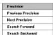
- Previous Precision: Selecting Previous Precision moves to the previous precision level starting with the window currently selected on the screen (Day → Minute → Hour → Day → ...). It is the same as pressing the COPY button on the front panel when in the EZ Search mode.
- Next Precision: Selecting Next Precision moves to the next precision level starting with the window currently selected on the screen (Day → Hour → Minute → Day → ...). It is the same as pressing the PLAY/STOP button on the front panel when in the EZ Search mode.
Operation Instruction
NOTE: While in the Day precision mode, "..." after the date information displayed on the camera screen indicates that the DVR has more than one video stream for the same date. Selecting the window and pressing the ⏻ button allows you to select the video stream you want to search and move to the next precision level. The highest Segment number indicates the latest video.
Bookmarks
The Bookmarks screen can also be accessed by selecting Bookmark in the Search menu.
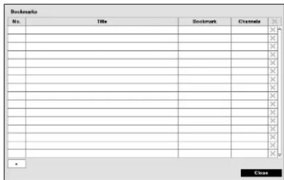
text_image
Bookmarks No. Title Bookmark Channels X X X X X X X X X X X X X X X X X X X X X X X X X X + CloseFigure 52: Bookmarks screen.
Highlight + and press the Ⓑ(Play/Pause) button to add the current playback point to the bookmark list. Highlight the Title box and enter the name of the registered bookmark. Use the virtual keyboard to enter the bookmark name. The ✗ column can be used to delete a Bookmark.
NOTE: Up to 64 bookmarks can be registered.
Use the arrow buttons to highlight the bookmark point for which you would like to see video. The selected bookmark will display on the screen by pressing the Ⓧ button.
Clip-Copy
Video clips can be copied on an external USB hard disk or flash drive. The copied video clips can be viewed on computers running Microsoft Windows 2000, XP, Vista or 7. Refer to the Appendix – USB Hard Disk Drive Preparation for information on preparing the external drive for clip copy.
Digital Video Recorder
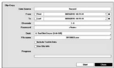
text_image
Grip Copy Data Source Record From First 09/23/2013 06:11:41 To Last 09/23/2013 06:11:11 Channel 1-0 PasswordFigure 53: Clip-Copy screen.
You can search video from the first to last recorded images, or you can set the start and stop times and dates.
Highlight the box beside From and press the Ⓗ(Play/Pause) button to toggle between On and Off. When set to Off, you can enter a specific Date and Time. When set to On, the search will be from the first recorded image. When highlighting ▼ and pressing the Ⓗ button the bookmark list displays and the bookmark point you selected will be the starting date and time.
Highlight the box beside To and press the button to toggle between On and Off. When set to Off, you can enter a specific Date and Time. When set to On, the search will be from the last recorded image. When highlighting and pressing the button the bookmark list displays and the bookmark point you selected will be the ending date and time. Highlight the box beside Channels and press the button. You can select the cameras that you would like to include in your video clip.
Highlight the box beside Password and press the Ⓧ button. A virtual keyboard appears allowing you to enter the password for reviewing the video clips.
Highlight the box beside Dest. and press the Ⓧ button. You can select the storage device on which you would like to record the video clip.
CAUTION: The USB device for clip copy must be FAT 16 or FAT32 format.
The DVR automatically assigns a file name to the video clip. However, you can give the video clip file a different name. Highlight the box beside File Name and press the button. A virtual keyboard appears. Enter a file name for the video you are backing up and select Close. The DVR will automatically add the camera number (for example "01") and "exe" to the file name.
NOTE: When naming a file you cannot use the following characters: / * 0 # ...
Operation Instruction
NOTE: The file size for clip copy is limited to 30GB. When copying video clips larger than 2GB, the video clips will be save in units of 2GB. For example, 3 individual 2GB files will be created when saving a 6GB video clip. However, the file size for the One-Touch Clip Copy is limited to 2GB.
You can use other functions on the DVR while video is being backed up. To do this, highlight the Close button and press the ⏻ button. You can return to the Clip-Copy screen at any time to check the progress.
You do not need to install any special software on your personal computer to review the video clips. Refer to Speco Central II manual for instructions on how to review video clips you have copied.
NOTE: During Clip Copy, you cannot shut the system down, clear data on the storage device, or format the storage device.
CAUTION: Do NOT disconnect the USB cable or the power from the external drive while copying video clips. If the external drive is shut down or the USB cable is disconnected while copying video clips, THE DVR SYSTEM MAY NOT WORK NORMALLY OR THE EXTERNAL DRIVE COULD BE DAMAGED, and you will get an error message the next time you try to copy video clips. You will need to power down the DVR and restart it to get rid of the error message. Once the file system of the USB hard disk drive has been corrupted, this error message cannot be dismissed. Even after restarting the DVR it may automatically restart while preparing to clip copy. You must recover the file system using the recovery program, or you must reformat the hard disk drive.
You can print images on a printer. Connect a PostScript™ printer, or external hard disk drive or flash drive to one of the USB ports.
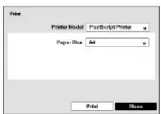
Highlight the box beside Printer Model and press the Ⓞ button. Selecting PostScript Printer will print images on a PostScript™ printer connected to the DVR. Selecting Filo Printer will save the current image as a PDF file on an external USB hard disk drive or flash drive.
NOTE: Images saved as PDF files can be printed on any printer connected to your PC.
Highlight the box beside Paper Size and press the ⏱ button. You can select the paper size.
Figure 54: Print screen.
Once you have selected the printer model and paper size, highlight the Print button and press the Ⓧ button. A message appears asking you if you want to print the current image. Highlight the Continue button and press the Ⓧ button to print.
Appendix
USB Hard Disk Drive Preparation
NOTE: The following description is for preparing a USB hard disk drive under Windows 2000. Preparing a USB hard disk drive under Windows XP, Window Vista and Window 7 is almost identical to Windows 2000.
- Connect the USB hard disk drive to your computer using the USB Cable.
- Turn on your computer.
- The USB device icon should display on the Taskbar.
- If the USB hard disk drive is partitioned or has data, it will show up in My Computer as a hard disk drive icon. Check the file system by right clicking on the icon and checking under Properties > General > File Format. With the file system in NOTU A172 format, format the USB hard disk drive using the UNT32 Format
System. If the file system is NOT FAT32 format, format the USB hard disk drive using the FAT32 format. - If the USB hard disk drive is not partitioned, go to Administrative Tools in Control Panel and launch Computer Management. Open Disk Management in Storage and right click an unallocated region of the USB hard disk drive. Then, click Create Partition.
- In the Create Partition wizard, click Next then Primary Partition, and follow the instructions on the screen. Make sure that the FAT32 is selected for the file system.
NOTE: The partition size should be less than 32GB because of Microsoft limitations.
After formatting is complete, the USB hard disk drive will be added to My Computer.
- Connect the USB hard disk drive to the DVR.
Text-In Search Examples
| Search Example I | ||||||
| 1 | 2 | 3 | 4 | 5 | 6 | |
| 123456789012345678901234567890123456789012345678901234567890 | ||||||
| Item | Unit price | Qty | amount | |
| Coke | 2.20 | 1 (s) | 2.20 | |
| Fanta | 2.20 | 1 (s) | 2.20 | |
| Hotdog | 3.50 | 3 (s) | 10.50 | |
| Pepsi | 1.95 | 1 (s) | 1.95 | |
total : \$ 16.85
Operation Instruction
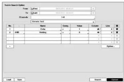
text_image
Tools Search Option From: To: Channels: 1-8 Search List No. - Name Comp Value Column Line 1 Color 1 2 3 X 2 AWD Holding > 0 1 2 3 X 3 4 5 6 7 8 9 10 11 12 13 14 15 16 17 18 19 20 Options... Load Name Search CancelSearch Example II
| 1 | 2 | 3 | 4 | 5 | 6 |
| 123456789012345678901234567890123456789012345678901234567890 | |||||
| Item | Unit price | Qty | amount | ||
| Coke | 2.20 | 1 (s) | 2.20 | ||
| Fanta | 2.20 | 1 (s) | 2.20 | ||
| Hotdog | 3.50 | 3 (s) | 10.50 | ||
| Pepsi | 1.95 | 1 (s) | 1.95 | ||
| total: $ | 16.85 | ||||
Thank you--
In the above text-in data, you can find that the comparison value is located at 17th (Unit price, S mark will be ignored automatically), 28^th (Qty) and 40^th (amount) characters (including spaces) from the left, but the value of amount category is located on a different line from Item. In this case, you can enter "17", "28" and "40" in each Column box and enter "1" in the Line box for the next line.
For example, if you want to search for Coke with a Qty (Quantity) of more than 1 and Hotdog with an amount totaling over S8, the following search condition can be set.
Speco Remote
Speco Remote allows you to access a remote DVR, monitor live video images and search recorded video using Internet Explorer web browser anytime from virtually anywhere.
Computer system requirements for using the Speech Remote program are:
- Operating System: Microsoft ^ Windows ^ XP (Service Pack 3), Microsoft ^ Windows ^ Vista (Service Pack 1),
Microsoft Windows 7 (Home Premium, Professional, Ultimate) or Microsoft Windows 8 (Pro, Enterprise)
• CPU: Intel Pentium III (Celeron) 600MHz or faster
• RAM: 128MB or higher
• VGA: 8MB or higher (1024x768, 24bpp or higher) - Internet Explorer: Version 6.0 or later (32-Bit)
Start Internet Explorer on your local PC. You can run the Speco Remote program by entering the following information in the address field.
- "http://IP address:port number" (The DVR IP address and the Speco Remote port number (default: 8204) set in the Network setup screen (Speco Remote tab))
- Or, "http://DVRNS server address/DVR name" (The DVRNS server address and the DVR name registered on the DVRNS server)
NOTE: You will need to get the appropriate IP address for the DVR you want to connect to and the Speco Remote port number from your network administrator.
Speco Remote only works with Microsoft Internet Explorer and will NOT work with other browsers.
Speco Remote does not work in Microsoft ^3 Windows ^8 8 metro UI.

Select between the Remote Watch (Web monitoring) and Remote Search (Web search) modes. Entering ID and PASSWORD and clicking the [LOGIN] button logs in using the selected mode.
NOTE: Do NOT close the LOGIN window during the Speco Remote operation, otherwise, it will cause a script error when switching between Web monitoring and Web search modes, and you will need to restart the Speco Remote program.
When running the updated Speco Remote for the first time, Internet Explorer might occasionally load the Information of the previous version. In this case, delete the temporary Internet files by selecting Tools → Internet Options → General tab, and then run Speco Remote again.
Operation Instruction
NOTE: There might be a problem with screen display or screen update due to low image transmission speed when using the Microsoft Windows Vista or higher operating system. In this situation, it is recommended that you disable the Auto Tuning capability of your computer.
Run the Command Prompt with elevated administrator permissions (Go to the Start Menu → Accessories → Command Prompt → Click the right mouse button and select the Run as administrator option). Then enter "netsh int tcp set global autotuninglevel=disable" and hit the enter key. Restart your computer to apply the changes.
If you want to enable the Auto Tuning capability again, enter "netsh int tcp set global autotuninglevel=normal" after running the Command Prompt with elevated administrator permissions. Restart your computer to apply the changes.
Web Monitoring Mode
Remote Watch is a remote web monitoring program that allows you to monitor live video transmitted in real-time from the remote DVR.

text_image
Screenshot of a video editing interface displaying multiple surveillance feeds and real-time property displays, with Chinese text labels and UI controls.① Click the 📄 to log out the Speco Remote program.
② Click the 📄 to access to the web search mode.
B N O H
Digital Video Recorder
Click the 📄 to set up the image drawing mode and OSD display. You can adjust the display speed by changing the image drawing mode, and select OSD information to be displayed on the screen.
⑪ Click the 📄 to save the current image as a bitmap or JPEG file format.
⑫ The event status window at the bottom displays a list of events that were detected from the remote site.
⑬ Selecting a camera on the screen and clicking the right mouse button displays the text menu screen.
Change Camera Title Enable Audio Aspect Ratio Anti-aliasing Screen
- Change Camera Title: Changes the camera name.
- Enable Audio: Enables audio communication with the remote site. When the audio control panel displays, click the ☑ to send audio to the connected remote site and click the button again to stop sending audio. Click the ☑ to monitor live audio from the connected remote site through the attached speaker and click the button again stop monitoring live audio. Clicking both ☑ and ☑ follows two-way communication. Clicking the ✗ disables audio communication.
- Aspect Ratio: Changes the image aspect ratio.
- Anti-Aliasing Screen: Enhances image display quality by eliminating stair stepping (aliasing) effects in the enlarged image.
NOTE: A camera name change in the Remote Watch mode does not affect the camera name set up on the remote
site. Leaving the Camera Title blank causes the camera name set up on the remote site to display. The 📄 Icon will display on each camera screen when audio communication is available between the Speco Remote system and a DVR.
Web Search Mode
Remote Search is a remote web search program that allows you to search recorded video on the remote DVR.
NOTE: The remote site connection in the Remote Search mode will automatically be disconnected if there is no activity for 30 minutes.

text_image
Screenshot of a surveillance camera interface displaying multiple office scenes with Chinese text labels and UI controls.Operation Instruction
⑤ Click the ☐ to blur, sharpen, equalize and interpolate playback images. Click the ☐ to zoom out or zoom in the recorded image. Click the ☐ to adjust the brightness of the recorded images. NOTE: Image processing works only in the pause mode.
⑤ The playback function buttons include fast backward, pause, play, fast forward, go to the first image, go to the previous image, go to the next image, and got to the last image.
⑦ Click the screen format to select the desired display mode.
⑧ Click the 10 to enter the time-lapse search mode which allows you to search for recorded data by time and then play back images found within the time parameters. The Timetable window located at the bottom displays the time information for the image of the date selected on the calendar. If more than one video stream in the same time range, you can select the video stream you want to search. Clicking a specific time displays the image recorded at that time on the screen. Selecting the 10 allows you to display an image from a specific time.
⑧ Click the to enter the event search mode which allows you to search for event log entries using specific conditions and play back the images associated with those event entries.
Click the 📄 to set up the image drawing mode and OSD display. You can adjust the display speed by changing the image drawing mode, and select OSD information to be displayed on the screen.
⑪ Click the ☐ to save any video clip of recorded data as an executable file, or click the ☐ to save the current image in a bitmap or JPEG file format. Click the ☐ to print the current image on a printer connected to your computer.
NOTE: When saving as an executable file, selecting the Exclude Player option will reduce the file size and its saving time. You can download the Player program to review the video clip by entering the following information in the address field of Internet Explorer.
- When using the DVRNS: "http://DVRNS server address/DVR Name/ClipPlayer.exe" (The DVRNS server address and the DVR name registered on the DVRNS server)
- When not using the DVRNS: "http://IP address:port number/ClipPlayer.exe" (The DVR IP address and the Speco Remote port number (default: 12088) set in the Network setup screen (Speco Remote tab))
⑫ Click the ■ to reload the recording data.
⑬ The Timetable displays recorded data of the selected camera by time (in hour segments).
04 Selecting a camera on the screen and clicking the right mouse button displays the text menu screen.
| Change Camera Title |
| Enable Audio |
| Aspect Ratio |
| Anti-aliasing Screen |
- Change Camera Title: Changes the camera name.
- Enable Audio: Plays audio while playing back recorded video that has recorded audio. (Single-Screen Layout Only)
- Aspect Ratio: Changes the image aspect ratio.
- Anti-Aliasing Screen: Enhances image display quality by eliminating stair stepping (aliasing) effects in the enlarged image.
NOTE: A camera name change in the Remote Search mode does not affect the camera name set up on the remote site. Leaving the Camera Title blank causes the camera name set up on the remote site to display.
Digital Video Recorder
Time Overlap
If the DVR's time and date have been reset to a time that is earlier than the existing recorded video, it is possible for the DVR to have more than one video stream in the same time range. In this case, you can search overlapping video streams individually by selecting a specific segment. For example, when the DVR has recorded video from one to five o'clock and the user changes the time backward from five to three o'clock and then continues recording until six o'clock, there will be two video streams and segments from three to five o'clock.
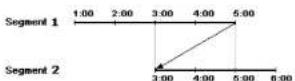
You can search overlapping video streams by selecting a specific time or time range. If you want to search recorded video at four o'clock during the overlapping time range using a search menu such as Go to the Date/Time, select the segment you want to search.

If you want to search recorded video from four to five o'clock during the overlapping time range using a search menu such as Event Log Search, Text-In Search or Motion Search, it is possible for the DVR to have two overlapping start and stop times. You will be asked to select one of the overlapping start and stop times from the search time ranges as follows:
- From four o'clock of the first segment to five o'clock of the first segment
- From four o'clock of the first segment to five o'clock of the second segment
- From four o'clock of the second segment to five o'clock of the second segment

Error Code Notices
| System Upgrade Related Clip Copy Related | |||
| No. | Description | No. | Description |
| 1 | 2 | 3 | 4 |
Operation Instruction
| System Upgrade Related Clip Copy Related | |||
| No. | Description | No. | Description |
| 302 | Remote upgrade is not authorized. | 13 | No executable file. |
| 303 | Saving remote package failed. | 14 | Opening executable file failed. |
| 304 | Remote upgrade is cancelled by the user. | 15 | Writing executable file failed. |
| 400 | USB device mounting failed. | 16 | Creating image failed. |
| 401 | Reading upgrade package on the USB device failed. | 19 | Connecting device failed. |
| 402 | Copying upgrade package on the USB device failed. | 20 | Device is busy. |
| 403 | USB device is not connected. | 21 | Unsupported file system. |
| 404 | USB device is being used. | 22 | Verify failed. |
| 405 | Unsupported file system. | ||
| 500 | System is busy clip copying. | ||
System Log Notices
| Boot Up Format Disk | |
| Shutdown | Disk |
| Restart Disk Config Change | |
| Upgrade Disk 'No.' : 'social number' | |
| Upgrade Fail Disk 'No.' : Removed | |
| Power Failure Auto Deletion | |
| Time Change Search Begin | |
| Time Zone Change Search End | |
| Time Sync Clip-Copy Begin | |
| Time Sync Fail Clip-Copy End | |
| Disk Bad Clip-Copy Cancel | |
| Login | Clip-Copy |
| Logout | Clip-Copy User: |
| Setup Begin | Clip-Copy From: |
| Setup End | Clip-Copy Tu: |
Full
Fail
Digital Video Recorder
Map of Screens
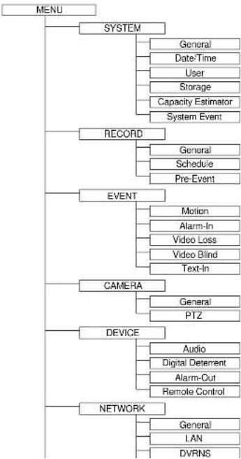
flowchart
graph TD
    A["MENU"] --> B["SYSTEM"]
    B --> C["General"]
    B --> D["Date/Time"]
    B --> E["User"]
    B --> F["Storage"]
    B --> G["Capacity Estimator"]
    B --> H["System Event"]
    A --> I["RECORD"]
    I --> J["General"]
    I --> K["Schedule"]
    I --> L["Pre-Event"]
    A --> M["EVENT"]
    M --> N["Motion"]
    M --> O["Alarm-In"]
    M --> P["Video Loss"]
    M --> Q["Video Blind"]
    M --> R["Text-In"]
    A --> S["CAMERA"]
    S --> T["General"]
    S --> U["PTZ"]
    A --> V["DEVICE"]
    V --> W["Audio"]
    V --> X["Digital Deterrent"]
    V --> Y["Alarm-Cut"]
    V --> Z["Remote Control"]
    A --> AA["NETWORK"]
    AA --> AB["General"]
    AA --> AC["LAN"]
    AA --> AD["DVRNS"]
Operation Instruction
Troubleshooting
| Problem Possible Solution | |
| No Power | Check power cord connections.Confirm that there is power at the outlet. |
| No Live Video | Check camera video cable and connections.Check monitor video cable and connections.Confirm that the camera has power.Check camera lens settings.Check the current main monitor resolution. |
| DVR has stopped recording | If hard disk drive is full, you will either need to delete video or set the DVR to the Overwrite Mode. |
| The icon displays,however, the DVR is not recording. | When the DVR is in the Pre-Event recording mode, the yellow and display when there is no event, and the DVR is not recording. The red and display when any event occurs and the DVR starts recording. |
| While upgrading the system,the DVR keeps rebooting andthe upgrade fails. | If the current system version is higher than the upgrade package file version, you should reset the DVR first using the Factory Reset. When using the Factory Reset,you will lose any settings you have saved. |
Specifications
| VIDEO | |
| Signal Format NTSC or PAL (Auto Delect) | |
| Video Input Composite: 4 or 8 inputs, 1 Vp-p, auto-terminating, 75 Ohms | |
| Monitor Outputs | HDMI: 1 HDMIVGA: 1 |
| Vidco Resolution | HDMI: 1920x1080, 1440x900, 1280x1024VGA: 1920x1080, 1440x900, 1280x1024 |
| Record Speed(images per second) | Real-time: 240ips (NTSC), 200ips (PAI.) @ D1/960H (8-ch Model)120ips (NTSC), 100ips (PAI.) @ D1/960H (4-ch Model) |
| Playback Speed(images per second) | Full Duplex: 240ips (NTSC), 200ips (PAL) @ CIF/Q960H (8-ch Model)120ips (NTSC), 100ips (PAL) @ D1/960H (4-ch Model) |
INPUTS/OUTPUTS
Digital Video Recorder
| CONNECTORS | |
| Video Input Composite: 4 or 8 BNC | |
| Monitor Output | HDMI: 1 HDMI VGA: 1 VGA |
| Audio In 4 RCA connector | |
| Audio Out 1 RCA connector | |
| Alarm Input/Output Terminal Blocks | |
| Ethernet Port RJ-45 | |
| RS232 Serial Port Two-connector terminal block | |
| RS485 Serial Port Two-connector terminal block | |
| IR Port 1 Remote Control | |
| USB Port 2 (USB 2.0) | |
| STORAGE | |
| Primary Storage SATA hard disk drive | |
| Secondary Storage USB hard disk drive or flash drive | |
| GENERAL | |
| Dimensions (W x H x D) 10.4" x 2.0" x 7.5" (265mm x 52mm x 191mm) | |
| Unit Weight 3.3 lbs. (1.48kg) | |
| Shipping Weight 6.0 lbs. (2.73kg) | |
| Shipping Dimensions(W x H x D) | 14.0" x 4.1" x 13.4" (355mm x 103mm x 340mm) |
| Operating Temperature 41°F to 104°F (5°C to 40°C) | |
| Operating Humidity 0% to 90% | |
| Power | 12V, 2A (Adaptor: 100-240V-, 50/60Hz, 1.5A, 12V, 5A) |
| Power Consumption | Max. 25W |
| Approvals | 1CC, CE |
Specifications are subject to change without notice.