O2D3 - Security Camera Speco Technologies - Free user manual and instructions
Find the device manual for free O2D3 Speco Technologies in PDF.

User questions about O2D3 Speco Technologies
0 question about this device. Answer the ones you know or ask your own.
Ask a new question about this device
Download the instructions for your Security Camera in PDF format for free! Find your manual O2D3 - Speco Technologies and take your electronic device back in hand. On this page are published all the documents necessary for the use of your device. O2D3 by Speco Technologies.
USER MANUAL O2D3 Speco Technologies
Be careful not to cause any physical damage by dropping or throwing ONSIP O2D3. Especially keep the device out of reach from children.
Do not disassemble ONSIP O2D3. No After Service is assumed when disassembled.
Use only the power adapter provided with ONSIP O2D3.
Be careful to prevent moisture or water penetration into the unit. Particular attention is needed when installing ONSIP O2D3. The screw holes for the installation screws and pipe should be maintained water tight during the whole life time of the product.
All the electrical connection wires running into the unit should be prepared so that water from the outside cannot flow into the unit through the surface of the wires. Penetration of the moisture through the wire for extended period can cause malfunction of the unit or deteriorated image.
Note
This equipment has been tested and found to comply with the limits for a Class a digital device, pursuant to part 15 of the FCC Rules. These limits are designed to provide reasonable protection against harmful interference in a residential installation. This equipment generate, uses and can radiate radio frequency energy and, if not installed and used in accordance with the instructions, may
Caution
Any changes or modifications in construction of this device which are not explicitly approved by the party responsible for compliance could void the user's authority to operate the equipment.
Revision History
| Date | Revision | Details |
| 2011-11-01 | 1.0 | First manual revision creation. |
Contents
Contents 4
- Introduction......5
1.1. Overview 5
1.2. Specification 6
1.3. Applications of ONSIP O2D3 8
- Product Description 9
2.1.Contents 9
2.2. Product Preview 10
2.3. Physical description....11
2.4. Functional Description....15
2.5. Accessories for installation 18
- On Site Installation 20
3.1. Ceiling mount 20
3.2. Wall mount (option) 21
3.3. Ceiling mount (option) 22
3.4. Embedded Ceiling Mount (Option) 23
3.5. Installation Environment 25
- Getting Started....26
4.1. PC Requirement....26
1. Introduction
1.1. Overview
The ONSIP O2D3 is a state-of-the-art mega-pixel, multi-codec (H.264, MJPEG) IP camera (or network camera) built with embedded software and hardware technology. It enables real time transmission of synchronized video of up to 2 M pixels and audio data. Remote clients can connect to ONSIP O2D3 for the real time video/audio data through various client solutions running on PC, PDA or mobile phones. Real time 2-way communication is available through bidirectional audio communication feature.
Designed to be a stand-alone streaming audio & video transmission device. ONSIP O2D3 can be applied to various application area such as video security, remote video monitoring, distance education, video conference or internet broadcasting system.
Vandal proof housing satisfying IP-66 and fan/heater will extend the application area to harsh environment of wide temperature range.
Embedded PoE (Power over Ethernet, IEEE 802.3af) will enable the owner to reduce TCO (Total Cost of Ownership) by reducing on-site wiring works for the installation.
1.2. Specification
| Category | Sub-Category | Details | |
| Video | Compression | H.264 / MJPEG | |
| Resolution | * Refer to the datasheet. | ||
| Camera Module | Mounting Gimbal | 3 Axis Gimbal(Manual Pan/Tilt adjustment &camera module rotation for rotating image) | |
| Audio(Bi-directional) | Up | 32 Kbps G.726 | |
| Down | 64 Kbps PCM | ||
| Network | Interface | RJ-45, 10/100 Mbps, PoE (802.3af) | |
| Access network | Static, DHCP, PPP/PPPoE | ||
| Application | RTP, RTSP, SMTP, FTP, HTTP, SDP, NTP, DNS | ||
| I/O | Sensor In | 1 | NC, NO Selectable |
| Relay Output | 1 | For alarm annunciation orremote ON/OFF control (30V, 1A) | |
| RS-232C | For factory use only | ||
| Mic/Line In | Selectable in Admin page | ||
| Line Out | 1 V p-p output for amplified speaker | ||
ONSIP O2D3 Owner's Manual
| Dynamic IP support | DDNS support | Supported |
| Security | Video/Audio stream encryption | |
| ID and Password protection | ||
| IP filtering for restricting administrative access for audio and bi-audio | ||
| Time management | Sync to PC | Synchronize to PC |
| Manual | Manual time setting | |
| Internet Time Server | Synchronize to Time Server | |
| SDK support | Active-X | |
| HTTP | ||
1.3. Applications of ONSIP O2D3
- Security surveillance (buildings, stores, manufacturing facilities, parking lots, banks, government facilities, military, etc.)
- Remote monitoring (hospitals, kindergartens, traffic, public areas, etc.)
• Teleconference (Bi-directional audio conference). Remote Learning, Internet broadcasting
• Weather and environmental observation
2. Product Description
2.1. Contents
The product package contains followings:
| Contents | Description | Remarks |
| ONSIP O2D3 | IP camera ONSIP O2D3 main unit | |
| Power Adaptor | Default built in standard PoE module (IEEE802.3af) | 12VDC Adaptor(Optional item) |
| Tools and Mounting Screws | Screws, Rubber rings, Mount cap,L-type wrench, Mount cap key | Basic tools and hardware(screws, rubber ring)needed for mounting ONSIP O2D3. |
| CD | Software & User's Guide | |
| Quick Reference Guide | Quick installation guide |
2.2. Product Preview
| ONSIP O2D3 | IP-Installer | CMS Software (NVR) |
 |  | 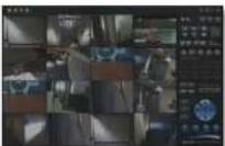 |
| Vandal Proof (Megapixel) Mini Dome IP Camera | PC software to allocate an IP address to the IP Camera | PC software to view and record the A/V streaming data transmitted from IP camera. (Simultaneous support of up to 64 IP cameras) |
2.3. Physical description
2.3.1. External View

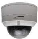
natural_image
Close-up of a white and black spherical security camera with a glossy dome and a small screw base (no visible text or symbols)Front

2.3.2. Internal Structure

text_image
Tamper Proof Screws Dome Cover Conduit Hole (Side) Dome Base Conduit Hole (Bottom)Figure 2-2. Internal structure of ONSIP O2D3

natural_image
Pure technical line drawing of a mechanical component without any text, numbers, or symbols
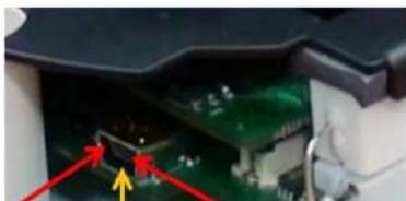
text_image
Factory Default Switch Video Output (CVBS, GND)Figure 2-4. Factory Default switch and Video output connector
natural_image
Close-up of a computer motherboard with visible circuit board and connectors (no text or symbols)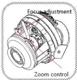
text_image
Focus adjustment Zoom controlFigure 2-6. Adjustment knobs for the Camera
natural_image
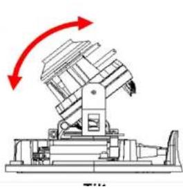
Technical line drawing of a mechanical device with red arrows indicating rotational motion (no text or symbols)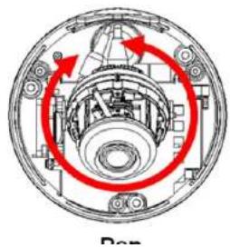
natural_image
Cross-sectional diagram of a mechanical assembly with red arrows indicating rotational direction (no text or symbols)2.4. Functional Description
- DC 12V, 2A: Power input for supplying 12V DC power.

Caution: If ONSIP O2D3 is powered by PoE, do not plug in DC Jack with active DC power into DC power connector.
- MIC/LINE IN
Connect external audio source or microphone.
• Line Out
Connect speakers with built in amplifier. Audio from remote site is output through Line out in bi-directional audio mode.
- 100Base-T
100Mbps Ethernet connector (RJ-45) with PoE standard (802.3af). 2 LEDs on the Ethernet connector shows the status of ONSIP O2D3 as the followings:
- Status LED (Dual Color - Red/Green): It will be lit in green or red depending on the status.
① Green: Green color indicates that the camera is in normal operation mode. Continuous green indicates that data transmission is possible. Blinking green means that someone is connected to ONSIP O2D3.
② Red: Continuous or blinking red indicates that hardware is in abnormal condition
| 1 | Not used | |
| 2 | Not used | |
| 3 | RxD (Connect to TxD of the other end) | For debugging & factory use only. |
| 4 | TxD (RxD (Connect to RxD of the other end)) | |
| 5 | Ground of RS-232C |
• Alarm In/Out and Audio In/Out
Used for connecting alarm sensor, alarm annunciation device, microphone and speaker to ONSIP O2D3.
| Description | |
| LINE OUT (+) | 1 V p-p audio signal output for amplified speaker. |
| MIC/LINE GND (-) | Ground for audio signals. |
| MIC/LINE IN (+) | Audio input: Can be used either for microphone or applying audio signals from other audio equipment. |
| SENSOR IN | Sensor In (+). NC/NO selectable in admin mode. |
| SENSOR IN GND | Ground for sensor |
| RLY OUT(COM) | Relay output : Circuit will be closed in alarm to indicate alarm status |
| RLY OUT(N.O) |
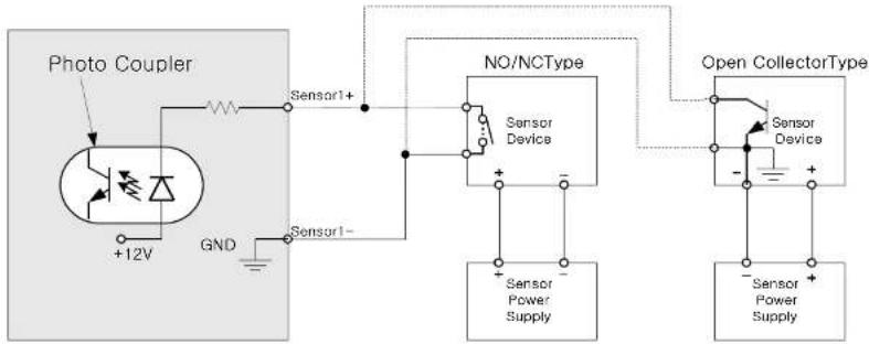
- RLY Out: Relay output is provided for connecting alarm devices or for remote on/off control of devices such as light. Relay is normal open and it will be closed upon alarm annunciation or remote on. The relay is capable of switching 30V AC/DC, 2A. For the application which needs power switching beyond this limit, use additional relay switch as shown in the right of Figure 2-8.
"SNS In". The sensor type (NC/NO) can be set in admin page. 10 mA can be sunk into sensor device. Multiple sensor devices can be connected in parallel.
flowchart
graph TD
    A["Photo Coupler"] --> B["+12V"]
    B --> C["GND"]
    C --> D["Sensor1+"]
    D --> E["NO/NCType Sensor Device"]
    E --> F["Sensor Power Supply"]
    E --> G["Sensor Power Supply"]
    H["Open CollectorType"] --> I["Sensor Device"]
    I --> J["Sensor Power Supply"]
    I --> K["Sensor Power Supply"]
Figure 2-9. SENSOR input and connection of the sensor
- Factory Default Switch
A switch provided for returning the IP camera to factory default state. Open the dome cover to access the switch. Press the switch for a few seconds while power is applied.


2.5. Accessories for installation
text_image
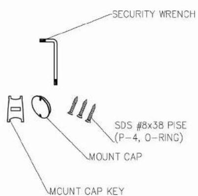
SECURITY WRENCH SDS #8x38 PISE (P-4, O-RING) MOUNT CAP MOUNT CAP KEYFigure 2-11. Accessories for installation of ONSIP O2D3. Silica gel at the right is packaged in a vacuum sealed PVC bag.
1
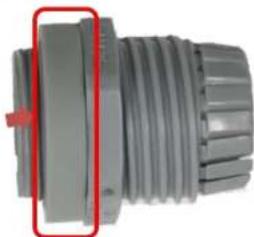
natural_image
Close-up of a gray threaded mechanical component with a red arrow pointing to a section (no visible text or symbols)2
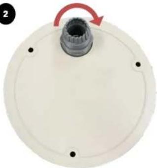
natural_image
Circular mechanical component with a central gear and red arrow indicating rotation (no text or symbols)LAN Cable
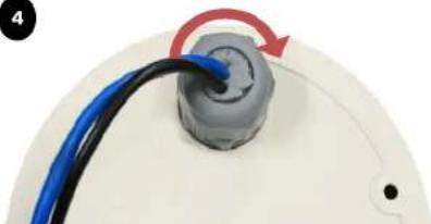
natural_image
Close-up of a mechanical component with blue and red arrows indicating direction (no text or symbols)4
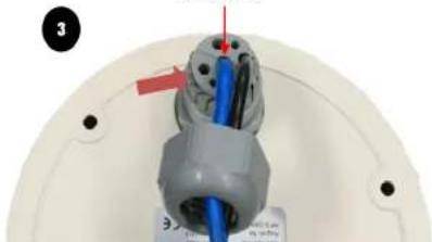
natural_image
Close-up of a mechanical component with blue and black wires, no visible text or symbols3. On Site Installation
Use Cables and conduits that are suitable for the installation and that are compliant to IP-66. Particular attention should be paid in the installation so that no moisture is allowed to penetrate into the unit through the cables or conduits during the life time of the product. Products of which the internal parts are exposed to moisture because of improper installation are not covered by warranty.
3.1. Ceiling mount
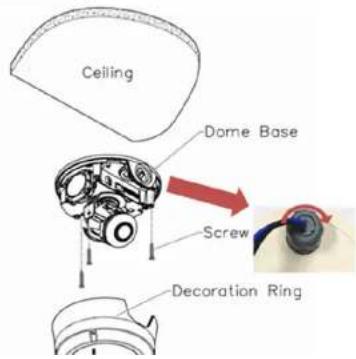
text_image
Ceiling Dome Base Screw Decoration Ring- Fix the Dome Base on the ceiling panel. The rubber gasket should be placed properly to ensure water tightness after placing the Dome Cover.
- Connect the cables.
- Adjust the position of the lens for desired viewing of the site.
- Adjust the focus and zoom.
- Place the Dome Cover.
3.2. Wall mount (option)

text_image
BRACKET WALL(V3) RUBBER(BRACKET WALL) RUBBER ADAPTOR MS PH M4 x 10 SUS 4EA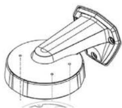
natural_image
Technical line drawing of a mechanical component with a circular base and protruding shaft (no text or symbols)- Assemble the wall mount bracket assembly.
- Run the cable through the bracket and attach the mount onto the wall.
- Fix the Dome Base into the bracket. The rubber gasket should be placed properly to ensure water
3.3. Ceiling mount (option)
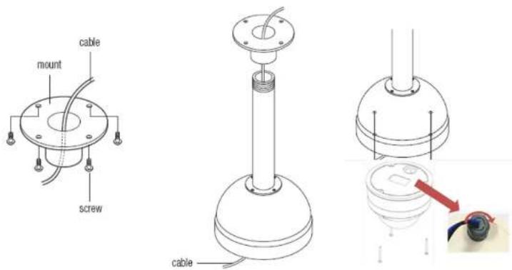
text_image
cable mount screw cable- Fix the mount bracket onto the ceiling
- Run the cable through the bracket.
- Fix the Dome Base into the bracket. The rubber gasket should be placed properly to ensure water tightness after placing the Dome Cover.
- Connect the cables.
- Adjust the position of the lens for desired viewing of the site.
3.4. Embedded Ceiling Mount (Option)
Components

In Ceiling Housing
In Ceiling Place

Decoration Hing

Tun Bao

Who Jain!

SCREW TM W*8 (With D-ring)

Eyn Bolt

Wire Rope

SCREY PE MO*78
Garcia/Garcia/Garcia
To an operation, please note the order
A placar intersegment par
19807 de 2019
vapilar desecanamato ala parlorine and melo
Gene(s)1A
- Installation
- Prepare the connecting wires and pipes for the wires.
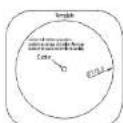
- Prepare a round hole (173.6 +/- 5mm in diameter) for the installation of the product on the ceiling panel.

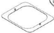
text_image
Template Another table lighting preference preposition is unique to the other differences preposition is unique to the table or preference CenterConhor/Contral/Fronto
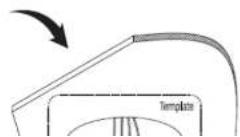

text_image
In Ceiling Plate coiling pad [A] Turn rope [B]- Sit "Dome Base" in "In Ceiling Housing"
- Connect the wires and finish pipe works.
- Adjust the manual Pan/Tilt/Video rotation for desired viewing of the site.
- Adjust the focus and zoom.
- Place the Dome Cover
- Set the "Decoration Ring" to finish.
3.5. Installation Environment
ONSIP O2D3 has fan and heater installed inside the product for wide range of environmental temperature.
Refer to the tables below for the temperature range of operation.
Operational temperature range
| Power Supply | Operational Temperature(°C) | Humidity (% Relative Humidity) | Misc | |
| Low | High | |||
| Standard PoE | -15 | 45 | 8-80% | Operational temperature (Low): Lower limit of temperature for the equipment to start running.Operational temperature (High): Upper limit of the temperature for the image sensor to provide defect free video. |
| DC Jack | -20 | 45 | 8-80% | |
Starting operation in low temperature
If ONSIP O2D3 is powered up under low temperature environment, the internal heater will warm up the product until the temperature inside the product reach at proper operational temperature. The table below shows time required for the heater to warm up the product.
Note that warming up can take long time under low temperature below zero in Celsius.
| Power Supply | Environmental Temperature (°C) | Warming up Time (Max in minutes) | Misc |
| Standard PoE | -10 | 10 | ONSIP O2D3 might not start running under temperature below -16°C |
| -15 | 20 |
4. Getting Started
Brief information for first time operation of ONSIP O2D3 is provided in this chapter.
4.1. PC Requirement
Audio/Video streaming data received from ONSIP O2D3 can be displayed or stored in a PC running client programs. Minimum requirement of the PC is described below:
| Recommended | Remark | |
| CPU | Pentium IV 3G above | |
| Main Memory | 1GB above | |
| Operating System* | Windows XP | |
| Web Browser | Internet Explorer 6.0 above | |
| Graphic Card | 64M above | Higher than 1600x1200 |
| Network | 100 Base-T Ethernet |
4.2. Quick Installation Guide
- Connect PC and ONSIP O2D3 to network.
1) Prepare a PC to run programs for the installation and video connection (PC is needed to assign IP address to ONSIP O2D3)
2) In the case of using PoE, connect the PC and ONSIP O2D3 to the network using one of the following ways.
If your LAN Switch does not support standard PoE, connect ONSIP O2D3 as shown in dotted line in Figure 4-1. The DC power is applied through DC adaptor.

flowchart
graph LR
    A["Computer"] --> B["LAN switch"]
    B --> C["LAN switch with standard POE"]
    C --> D["DC adaptor"]
Figure 4-1. Power and network connection
2. Install Speco-NVR
Speco-NVR is a multi-channel CMS program for to IP camera or Video server. Install Speco-NVR on remote PC to connect to these products. It is needed to assign connection information to Speco-NVR program before connection.
Insert the CD provided with product into the PC and install the Speco-NVR.
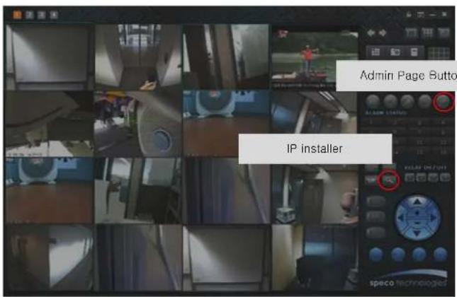
text_image
Admin Page Button IP installerONSIP O2D3 Owner's Manual

text_image
IP Installer MAC Address IP Address Name No Refresh Set Admin Port Refresh Default Adapter About Exit 1 2 3 4 5 6 7 Net Mode Static System Name Web Port RTSP Port Management Server Clone MAC UPnP Disable UP Static ADSL(PPPoE) Auto(DHCP) IP Address Subnet Mask Gateway DNS1 DNS2 Service Name User Name Password WLAN SSID Auth. Type EncryptType WLAN Key Network Adapter ©Device\WINPF_14580157E-6F24-4AC1-5382-GEED57E3FAB13. Remote video connection to ONSIP O2D3
1) Connection through Web Viewer
Web Viewer offers simplest way of video connection to ONSIP O2D3. For video connection, enter the IP address of ONSIP O2D3 in the URL window of Internet Explorer as:
[e.g.] Port 80
http://172.16.64.133/
Can be omitted the default port of 80
[e.g.] Port 8080
http://172.16.64.133:8080/

Note : Active-X module should be installed on your PC before actual connection. If your PC is not connected to the internet, you cannot download Active-X module. Most convenient way of installing the Active-X module is installing Speco-NVR which is available from the CD or our web site.
Connection to Admin Page
Basic Control Buttons
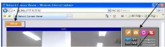
text_image
Network Camera Server - Windows, Internet Explorer May 27 10:31:32 Network Camera Server OK OK2) Connection through Speco-NVR
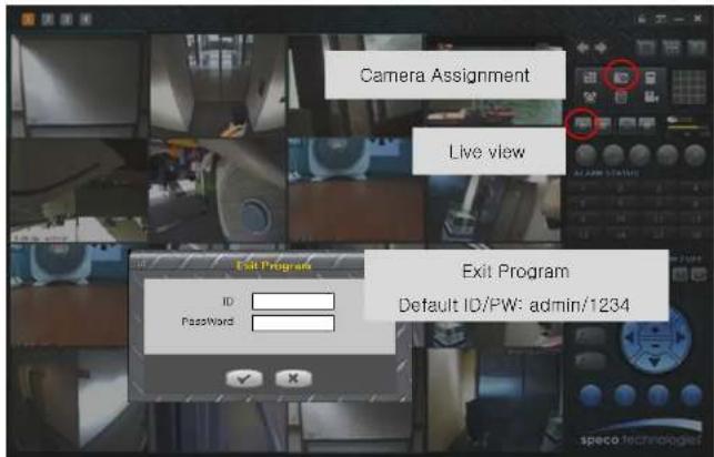
Click the camera assignment button for setting camera address. Input the description, address, Ch#, User ID, Password and port and then click the save button. After assignment procedure, you must click the SAVE button. You can see the live video when you click the live view button as below. When you exit Speco-NVR, you have to input the ID/PW, admin/1234. Details for the Speco-NVR can be found in [Speco-NVR User's Guide].
text_image
Camera Assignment Live view Exit Program Default ID/PW: admin/1234
Camera Assignment

4. Additional settings through connection to the Admin Page
All the parameters of new IP camera follows factory default values. For more sophisticated target application it is needed to change parameters. The admin page can be connected through
"http://IP_address:HTTP_port_number"/admin.htm
It is needed to enter ID and password of the administrator. Default ID and password are root, admin. It is highly recommended to change the ID and password to prevent illegal access to the IP camera. For more detailed information, please refer to the [Configuration_Guide] Guide.
5. Trouble Shooting
5.1. No power is applied
- In case of Standard PoE (Power over Ethernet)
Power supply through standard PoE is possible only when the following conditions are met.
- Standard PoE is supported on the product.
- The LAN switch supports standard PoE.
Make sure that both the IP camera and the LAN switch support standard PoE (IEEE 802.3af)
• In case of DC adaptor
If PoE is not applied, the power and network connection should be made through separate cables. It is recommended to use DC adaptor supplied by provider for the feeding of the power. In case of replacing the DC power supply, make sure that the power supply meets with the power requirement of the IP camera to prevent damage or malfunction.
5.2. Cannot connect to the Video
Check the status of the network connection through PING test.
Try the following on your PC :
- Start > Run > Cmd > Ping IP address (Ex : Ping 172.16.42.51)
- If "Reply from \~" message is returned (① in the figure below), the network connection is in normal state. Try connection to the video again. If the problem persists, or refer to other trouble shooting notes.
- If "Request timed out" message is returned. (② in the figure below), the network connection or network setting is not in normal state. Check the network cable and settings.

text_image
C:\WINDOWS\system32\cmd.exe Microsoft Windows XP (Version 5.1.2600) (C) Copyright 1985-2001 Microsoft Corp. C:\Documents and Settings\superman>ping 172.16.42.51 Pinging 172.16.42.51 with 32 bytes of data: Reply from 172.16.42.51: bytes=32 time\lmc TTL=64 Reply from 172.16.42.51: bytes=32 time\lmc TTL=64 Reply from 172.16.42.51: bytes=32 time\lmc TTL=64 Reply from 172.16.42.51: bytes=32 time\lmc TTL=64 Ping statistics for 172.16.42.51: Packets: Sent = 4, Received = 4, Lost = 0 (0x loss), Approximate round trip times in milli-sounds: Minimum = Bus, Maximum = Bus, Average = Bus C:\Documents and Settings\superman>5.3. Windows Vista or Windows 7
Windows Vista and Windows 7 users need to configure UAC (User Access Control) and Privilege Level for proper recording and still video capture in Speco-NVR and Web Viewer.
1. UAC (User Access Control) configuration
1) Double-click "User Accounts" in control panel
2) Double-click "Turn User Account Control on or off"
3) Uncheck "Use UAC to help protect your computer"

text_image
Control Panel Home System and Maintenance Security Maintenance and Internet Advanced and Second Programs User Accounts Parameters and Messages Clock, Language, and Programs Help Active Additional Options Close User User Accounts Add to remove password(s) Windows CardSpace Manage Information Calls that are used to log on its online services Close User Accounts Make changes to your user account Create a password for your account Change your password Change your account name Change your account type Change your account name Turn-on User Account Control is useful Turn-on User Account Control (SAC) to make your computer more secure Use Account Control (SAC) on help prevent unauthorized changes to your computer. It recommend that win-Your SAC should use the help protect your computer. ✓ Use Account Control (SAC) to help protect your computer
text_image
Open Troubleshoot compatibility Open file location Run as administrator Pin to Taskbar Pin to Start Menu Restore previous versions Send to Cut Copy Create shortcut Delete Rename Properties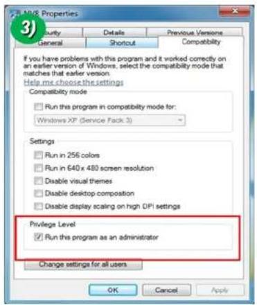
text_image
MUSE Properties Identity Details Previous Versions General Shortcut Compatibility If you have problems with this program and it worked correctly on an earlier version of Windows, select the compatibility mode that matches that earlier version. Help me choose the settings Compatibility mode Run this program in compatibility mode for: Windows XP (Service Pack 3) Settings Run in 256 colors Run in 640x 480 screen resolution Disable visual themes Disable desktop composition Disable display scaling on high DPI settings Privilege Level Run this program as an administrator Change settings for all users OK Cancel Apply1. UAC (User Access Control) configuration
1) Double-click "User Accounts" in control panel
2) Double-click "Change User Account Control setting"
3) Set to "Never notify"

2. Privilege Level Control
1) Select "NVR" icon on the desktop
2) Click right mouse button and select "properties"
3) Check "Privilege Level" in "Compatibility" tab

text_image
Open Troubleshoot compatibility Open file location Run as administrator Pin to Taskbar Pin to Start Menu Restore previous versions Send to Cut Copy Create shortcut Delete Rename Properties
text_image
MME Properties Security Details Previous Versions General Shortcut Compatibility If you have problems with this program and it worked correctly on an earlier version of Windows, select the compatibility mode that matches that earlier version. Help me choose the settings Compatibility mode Run this program in compatibility mode for: Windows XP (Service Pack 3) Settings Run in 256 colors Run in 640 x 480 screen resolution Disable visual themes Disable desktop composition Disable display scaling on high DPI settings Privilege Level Run this program as an administrator Change settings for all users OK Cancel Apply5.4. Technical Assistance
If you need any technical assistance, please contact your dealer. For immediate service please provide the following information.

- Model name
- MAC address and Registration number
- Purchase date
- Description of the problem
- Error message