ZIPL4B1 - Security Camera Speco Technologies - Free user manual and instructions
Find the device manual for free ZIPL4B1 Speco Technologies in PDF.

User questions about ZIPL4B1 Speco Technologies
0 question about this device. Answer the ones you know or ask your own.
Ask a new question about this device
Download the instructions for your Security Camera in PDF format for free! Find your manual ZIPL4B1 - Speco Technologies and take your electronic device back in hand. On this page are published all the documents necessary for the use of your device. ZIPL4B1 by Speco Technologies.
USER MANUAL ZIPL4B1 Speco Technologies
text_image
speco technologies®User Guide (Ver. 2.1)
Models: N4/8NSL
4/8 Channel Network Video Recorder
Cautions

text_image
CAUTION RISK OF ELECTRIC SHOCK DO NOT OPEN CAUTION: TO REDUCE THE RISK OF ELECTRIC SHOCK, DO NOT REMOVE COVER (OR BACK). NO USER SERVICEABLE PARTS INSIDE. REFER SERVICING TO QUALIFIED SERVICE PERSONNEL.Explanation of Graphical Symbols

This symbol indicates the presence of important operating and maintenance (servicing) instructions in the literature accompanying the product.

This symbol indicates the presence of "dangerous voltage" within the product's enclosure that may be of sufficient magnitude to constitute a risk of electric shock, property damage, personal injury, or death.
These precautions must be followed for safety reasons

Warning
- Do not use if the unit emits smoke.
- Do not disassemble the unit.
- Do not place any heavy or sharp objects on the unit.
- Do not place on uneven surface.
- Do not expose to shock or vibration.
- Do not move the unit when the unit is powered on.
- Do not block, and allow dust to accumulate in the air vents.
- Do not restrict airflow of the unit; doing so can damage the unit.
- Only qualified and experienced personnel should perform installation and servicing.
- Turn off the power of the NSL when connecting Cameras, Audio Cables.
- The manufacturer is not responsible for any damage caused by improper use of the product or failure to follow instructions for the product.
- The manufacturer is not responsible for any problems caused by or resulting from the user physically opening the NSL for examination or attempting to repair the unit.
- For NSL models with the PoE Switch, it is strongly recommended that the 48V
Product Components
Please make sure the following components are included as specified below.
| Desktop:N4NSL / N8NSL |  |
| Remote Control |  |
| Battery 1.5V (AAA x 2 EA) |  |
| Quick Setup Guide &User Guide |  |
| Mouse for NSL |  |
| Software & Manual CD |  |
| Power Adaptor(DC48V for POE)& Power cable (110V or 220V) |  N4NSL : 1.2A, N8NSL : 2A N4NSL : 1.2A, N8NSL : 2A |
Specifications for NSL
| MODEL NAME N4NSL N8NSL | ||||
| Description 4ch NVR with 4-PoE | 8ch NVR with 8-PoE | |||
| Video | Input | IP Camera (Throughput) 4 8 | ||
| Normal Resolution Max. | 920x1080 | |||
| Highest Resolution Not Support | ||||
| Output | Main Monitor VGA and Sub Monitor None | HDMI (Max. 1920x1080) | ||
| Audio | Input | IP Camera (Network) 4 8 | ||
| Local Input (RCA) None | None | |||
| Output | Local Output (RCA) 1 1 | |||
| Audio Codec | G.711 | |||
| Event | SensorIn | IP Camera (Network) 4 8 | ||
| Local Input (Terminal Block) | None None | |||
| Local Alarm Output (Terminal Block) | None None | |||
| Motion Detection (from IP Camera) | Yes | |||
| Serial | RS-232C | None None | ||
| RS-485 | None None | |||
| Network | Private (IP Camera, Auto Connection) | 802.3af x 4 | 802.3af x 8 | |
| LAN (IP Camera, Remote Access) | 10/100 Base-TX | 10/100/1000 Base-TX | ||
| Protocols | TCP/IP, UDP, DHCP, HTTP, NTP, SMTP, RTP, RTSP, ONVIF | |||
| Streaming | Relay of the IP Camera's Sub-stream | |||
| USB | Front 1 1 | |||
| Rear 1 1 | ||||
| User I/F Input Method IR, Mouse | ||||
| Features | Dynamic DNS Yes (Free DDNS) | |||
| Digital Zoom Yes | ||||
| DLS (Day Light Saving) Yes | ||||
| NTP (Network Time Protocol) Yes | ||||
| S.M.A.R.T Yes | ||||
| Internal Beep Yes | ||||
| Multi-Language Yes | ||||
| e-mail Notification Yes | ||||
| Network Access | 3G Mobile | iPad / iPhone / Android | ||
| Web Viewer | Windows (IE, Chrome, Firefox, Safari) | |||
| PC Client | Single / Multi Client and CMS (64 channels) | |||
| Remote Setup and Upgrade | Yes | |||
| Power | Power Supply Voltage | DC 48V 1.2A | DC 48V 2.0A | |
| Temperature | Operation | 41^ 104^ ( 5^ 40^ ) | ||
| Storage | 14^ 122^ ( -10^ 50^ ) | |||
| Humidity | Operation | 20% ~ 80% (Non-condensing) | ||
| Dimension | Unit Dimension (W x H x D) | 11.8' × 8.9' × 2.0' ( 300mm × 227mm × 53mm ) | ||
Please note that specifications and unit exterior design are subject to change without notification.
Table of Contents
- Main Features 10
- Initial Boot-up Process....11
2-1. Initial Boot up and Basic Time Setup.... 11
2-2. Setting up Daylight Savings Time....12
2-3. Setting NTP (Network Time Protocol)....12
2-4.EZ Setup 15
2-5. PoE Port Setup 17
2-6. IP Camera Setup (through Web Viewer page)....19
2-7. Dual Streaming....19
- Front and Rear Panels 20
3-1. Desktop Front Panel 20
3-2. Connectors ...... 20
3-3. Remote Control....21
- Setup NSL Series 22
4-0. Setup – Main Live Screen 22
4-1. Setup - IP CAMERA....23
4-1-1. Scan Menu....25
4-1-2. ONVIF Setup Menu....26
4-2. Setup - SYSTEM....28
4-3. Setup – RECORD Mode 34
4-3-1. Recording Schedules....35
4-4. Setup – Device Mode....36
4-4-1. Digital Deterrent....38
4-4-2. Alarm Box and Keyboard Controller Setup....39
5-3-1.EZSearch....56
5-3-2. Smart Search....57
5-3-3. Time Line Search....58
5-3-4. Event Search....58
5-3-5. Go To First Time....59
5-3-6. Go To Last Time....59
5-3-7. Go To Specific Time 59
5-3-8. Archive List .... 59
5-3-8. Log List....59
5-4. Play Mode....60
- Back Up....62
6-1. Still Image Backup onto USB Flash Drive....62
6-2. Video Backup onto USB Flash Drive during playback 62
6-2. EZCopy: Video Backup onto USB Flash Drive during playback....64
6-3. Transferring Still Images or Video from the ARCHIVE List....64
6-4. Playback of Backup Video....65
6-5-1. AVI Format....65
6-5-2. NSF Format....66
- Network Access Using the Multi-Sites Network Viewer 67
7-1. Overview....67
7-2. PC Requirements....67
7-3. Installation of the Program 68
7-4. Live Window....69
7-4-1.Main User Interface....69
7-4-2. Control Buttons 69
7-5. Search and Playback Window....70
7-7-6. Network 83
7-7-7.User Management....83
7-7-8. Storage 85
7-7-9. Remote Upgrade....85
7-7-10. Information....85
7-8. Operation....86
7-8-1. Addition, Delete, and Modify of NSL Sites....86
7-8-2. Connect and Disconnect....87
7-8-3. Still-image Capture During Live....88
7-8-4. Recording Video on Local PC During Live 89
7-8-5. Local Playback and Remote Playback....90
7-8-6. AVI Backup during Playback 92
-
Network Access Using the Web-Browser Viewer....94
-
Network Access Using the Smart Phone Viewer 96
9-1. App Viewer for iPhone....96
9-1-1. Live....96
9-1-2. PTZ Control 98
9-1-3. Playback....98
9-2. App Viewer for Android Phone....99
9-2-1. Live....99
9-2-2. Playback....100
9-2-3. PTZ Control 101
APPENDIX: Network Connection - LAN....102
APPENDIX: Network Connection – Internet and DDNS 104
1. Main Features
■ Automatic IP Camera Detection and connection (Plug & Play)
■ Easy Record, Copy and Setup
■ Easy Search by Thumbnail Preview
■ Easy Copy
■ Easy Network
■ Easy IP Camera Setup
NOTE: Under federal law, The Fourth Amendment to the U.S. Constitution, Title III of the Omnibus Crime Control and Safe Streets Act of 1968, as amended by the Electronic Communications Privacy Act of 1986 (18 U.S.C. § 2510, et seq.), and the Foreign Intelligence Surveillance Act of 1978 (50 U.S.C. 1801, et seq.) permit government agents, acting with the consent of a party to a communication, to engage in warrantless interceptions of telephone communications, as well as oral and electronic communications.
■ Covert camera operation provides enhanced security and administrator control
■ Dynamically programmable recording priority, motion detection, alarms and scheduling
■ Simple and Easy Graphic User Interface
■ Simple Scheduler
■ HDMI Output
■ VGA Output
■ Password to secure installation authorization
■ Network software supports 10/100Mbps
■ USB 2.0 port for video clip exporting and easy firmware upgrade via USB Flash Drive
2. Initial Boot-up Process
2-1. Initial Boot up and Basic Time Setup
- During the first boot up, the following logo will be displayed.

text_image
speco technologies- After the logo, select the language and set date and time as specified below.
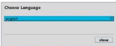
text_image
Choose Language english close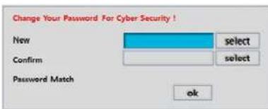
text_image
Change Your Password For Cyber Security ! New select Confirm select Password Match ok
text_image
Password 1 2 3 4 5 6 7 8 9 0 - = ← q m o i t y k i j o p l l Cape a s d f g h l k l + ' Cnul SALT Z x c v D n m . / Sltt Clear Space Close1) User has to set a password before using.
Cannot use "1111" when the initial boot up password set.
But user can set '1111' as a password through ISetup > User Management > Password Setup
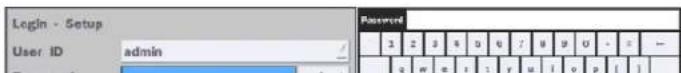
2-2. Setting up Daylight Savings Time
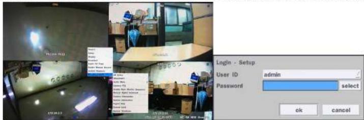
To enable Daylight Saving feature/NTP synchronization, take the following steps.
- Enter the Setup mode. The default User ID is "admin", and enter Password set on initial booting
text_image
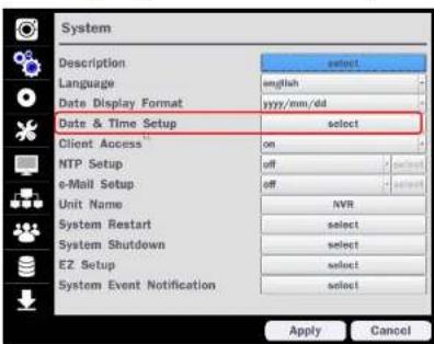
Login - Setup User ID Password admin select ok cancel- Go to Setup > System > Date & Time Setup
text_image
System Description Language Date Display Format Date & Time Setup Client Access NTP Setup e-Mail Setup Unit Name System Restart System Shutdown EZ Setup System Event Notification select on off off select select select select Apply Cancel- Select "on" from the Daylight Saving dropdown menu.
| Time Display Format | 24-hour Format |
| Time Zone | GMT -S00 (Montreal/New York) |
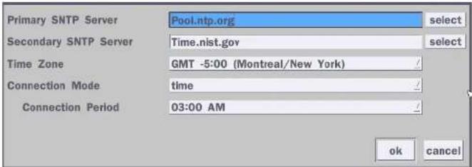
2. Select the proper Time Zone time.
text_image
Primary SNTP Server Pool.ntp.org select Secondary SNTP Server Time.nist.gov select Time Zone GMT -5:00 (Montreal/New York) Connection Mode time Connection Period 03:00 AM ok cancelTable2.3.1. GMT Time Zone
| State | Standard Time Daylight-Saving | Time | |
| AL Alabama | GMT-6 GMT-5 | ||
| AK Alaska | GMT-9 GMT-8 | ||
| AK Alaska (Aleutian Islands) | GMT-10 | NA | |
| AZ Arizona | GMT-7 | NA | |
| AZ | Arizona (Navajo) | GMT-7 GMT-6 | |
| AR | Arkansas | GMT-6 GMT-5 | |
| CA | California | GMT-8 GMT-7 | |
| CO | Colorado | GMT-7 GMT-6 | |
| CT | Connecticut | GMT-5 GMT-4 | |
| DC | District of Columbia | GMT-5 GMT-4 | |
| DE | Delaware | GMT-5 | GMT-4 |
| FL | Florida | GMT-5 | GMT-4 |
| FL | Florida (W) | GMT-6 | GMT-5 |
| MA Massachusetts GMT-5 GMT-4 | |||
| MI Michigan GMT-5 GMT-4 | |||
| MI Michigan (W) GMT-6 GMT-5 | |||
| MN Minnesota GMT-6 GMT-5 | |||
| MS Mississippi GMT-6 GMT-5 | |||
| MO Missouri GMT-6 GMT-5 | |||
| MT Montana GMT-7 GMT-6 | |||
| NE | Nebraska | GMT-6 GMT-5 | |
| NE | Nebraska (W) | GMT-7 GMT-6 | |
| NV | Nevada | GMT-8 GMT-7 | |
| NH | New Hampshire | GMT-5 GMT-4 | |
| NJ | New Jersey | GMT-5 GMT-4 | |
| NM New Mexico GMT-7 GMT-6 | |||
| NY | New York | GMT-5 GMT-4 | |
| NC | North Carolina | GMT-5 GMT-4 | |
| ND | North Dakota | GMT-6 GMT-5 | |
| ND | North Dakota (W) GMT-7 GMT-6 | ||
| OH | Ohio | GMT-5 GMT-4 | |
| OK | Oklahoma | GMT-6 GMT-5 | |
| OR | Oregon | GMT-8 GMT-7 | |
| OR | Oregon (E) | GMT-7 GMT-6 | |
| PA | Pennsylvania | GMT-5 GMT-4 | |
| RI | Rhode Island | GMT-5 GMT-4 | |
| SC | South Carolina | GMT-5 GMT-4 | |
| SD | South Dakota (E) | GMT-6 GMT-5 | |
2-4. EZ Setup
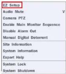
Quick installation menu for NS and IP Camera Easy installation(Right-Click on the main screen)
text_image
EZ Setup Audio Mute V Camera PTZ Enable Main Monitor Sequence Disable Alarm Out Manual Digital Deterrent Site Information System Information Export Help System Lock System Shutdown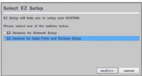
text_image
Select EZ Setup EZ Setup will help you to setup your SYSTEM. Please select one of the options below. • EZ Network for Network Setup • EZ Camera for Date/Time and Camera Setup next>> cancelFigure 2.4. EZ Setup Screen
2.4.1. Setup IP Camera configurations

text_image
Select EZ Setup EZ Setup will help you to setup your SYSTEM. Please select one of the options below. EZ Network for Network Setup EZ Camera for Data/Time and Camera Setup nextDate Cancel EZ Camera You are about to start EZ Camera EZ Camera will guide you through: - Data/Time Setup - Camera Setup Click the 'next' button to start EZ Camera Next Next Cancel EZ Camera Data/Time Setup Data Display Format mm/dd/yyyy Channel 8 IP Camera Info Product SPEDS Scan account IP 173.66.2.66 Port Total account EZ Camera2.4.2. EZ Network (Using an Internet connection)
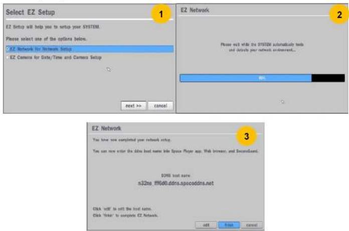
text_image
Select EZ Setup EZ Setup will help you to setup your SYSTEM. Please select one of the options below. EZ Network for Network Setup EZ Camera for Date/Time and Camera Setup next >> Cancel EZ Network Please not wait while the SYSTEM automatically tests and identify your network environment... 3 EZ Network You have now completed your network setup. You can now enter the data host name into Space Player app, Web browser, and Decoordnet. DENS test save n32ns_11660ddns.spccoddns.net Click 'call' to exit the test server. Click 'total' to complete EZ Network. add CancelFigure 2.4.2. EZ Network setup procedure
① Select EZ Network for Network Setup.
② NVR automatically trying to find an IP address.
③ Found address and user can edit the address.
④ Click "finish" to save the setup.
2.4.3. EZ Network setting (Not using internet connection)

① Select EZ Network for network setup.
② Select Auto Configuration(DHCP) or Manual Configuration(STATIC) and then click "test" button when ready.
③ Input the Network Settings if Manual Configuration(STATIC) was selected, and click "test"
④ Click "finish" to save the setup.
2-5. PoE Port Setup

text_image
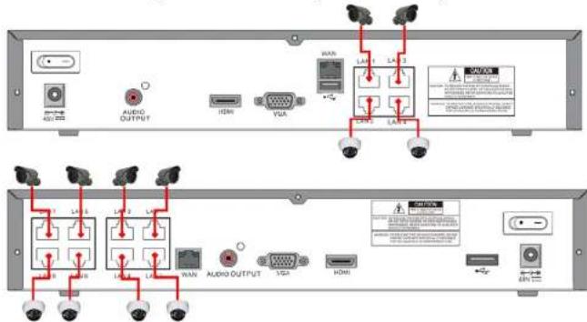
LAN 1 LAN 3 LAN 2 LAN 4 LAN 7 LAN 5 LAN 8 LAN 6 LAN 3 LAN 1 LAN 4 LAN 2Figure 2.5.1 PoE Port (N4NSL / N8NSL)
text_image
AUDIO OUTPUT HDMI VDA LAD 1 LAD 2 LAD 3 LAD 4 LAD 5 LAD 6 LAD 7 LAD 8 LAD 9 LAD 10 LAD 11 LAD 12 LAD 13 LAD 14 LAD 15 LAD 16 LAD 17 LAD 18 LAD 19 LAD 20 LAD 21 LAD 22 LAD 23 LAD 24 LAD 25 LAD 26 LAD 27 LAD 28 LAD 29 LAD 30 LAD 31 LAD 32 LAD 33 LAD 34 LAD 35 LAD 36 LAD 37 LAD 38 LAD 39 LAD 40 LAD 41 LAD 42 LAD 43 LAD 44 LAD 45 LAD 46 LAD 47 LAD 48 LAD 49 LAD 50 LAD 51 LAD 52 LAD 53 LAD 54 LAD 55 LAD 56 LAD 57 LAD 58 LAD 59 LAD 60 LAD 61 LAD 62 LAD 63 LAD 64 LAD 65 LAD 66 LAD 67 LAD 68 LAD 69 LAD 70 LAD 71 LAD 72 LAD 73 LAD 74 LAD 75 LAD 76 LAD 77 LAD 78 LAD 79 LAD 80 LAD 81 LAD 82 LAD 83 LAD 84 LAD 85 LAD 86 LAD 87 LAD 88 LAD 89 LAD 90 LAD 91 LAD 92 LAD 93 LAD 94 LAD 95 LAD 96 LAD 97 LAD 98 LAD 99 LAD 100Figure 2.5.1.1 IP Camera Connection Diagram (N4NSL. N8NSL)
Table 2.5.1. Factory Default of the IP Camera
The following IP Camera settings are recommended for optimal connection with the NSL Series
| Setup Items Default Description | ||
| Network Type DHCP | The IP Camera must act as a DHCP client for the “Plug and Play”. | |
| Encoding Type CBR The “CBR” | is recommended because of the internal buffer design of the NSL Series | |
| Resolution 1280x720 The maximum performance of the N8NSL is 1080p@240fps or 720p@240fps.To get higher frame rates per channel, 1280x720 is the recommended resolution. | ||
| Frame Rate 25fps The maximum performance of the N8NSL is 720p@240fps.Therefore 30fps per channel is recommended. (30fps x 8 = 240fps) | ||
| Bit Rate 2Mbps The maximum throughput of the N8NSL is 40Mbps.Therefore 2Mbps per channel is recommended. (4Mbps x 8 = 32Mbps) | ||
| Sub Stream CIF | 512Kbps | For “Dual Streaming”, the sub stream should be turned on.And for the proper streaming through the WAN connection,CIF@512Kbps or lower bitrates per channel is recommended. |
• The NSL Series features a "Plug and Play" function with a PoE Switch.
- The "Plug and Play" functionality requires the IP Camera to be in DHCP mode.
• The NSL automatically assigns an IP Address to the IP Camera. (10.20.30.11 \~ 10.20.30.254)
- The NSL models will automatically map the camera on the PoE Port to the corresponding NVR channel number.

flowchart
graph LR
    A["Device 1"] --> B["Switch"]
    C["Device 2"] --> B
    B --> D["Server"]
    style B stroke:#ff0000,stroke-width:2px
    style D fill:#f9f9f9,stroke:#333,stroke-width:2px
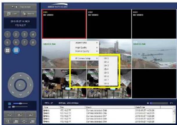
2-6. IP Camera Setup (through Web Viewer page)
NSL Series allow remote access to the IP Cameras through an "IP Camera Setup" menu.
The PC Web Client features the "IP Camera Setup" menu that can be accessed remotely.
text_image
MARCH Video/ACI/SER CISI NO VIDEO CISI NO VIDEO CISI NO VIDEO 1024 X 768 Aspect Video High Quality Normal Quality IP Camera Setup Oh=1 Oh=2 Oh=3 Oh=4 Oh=5 Oh=6 Oh=7 Oh=8 TPS: 37 E:\Rate: 2023.0KHz View Site Event Date Time 1018-05-27 14:23:29 1018-05-27 14:23:29 1018-05-27 14:23:29 1018-05-27 14:23:29 1018-05-27 14:23:29 1018-05-27 14:23:28 1018-05-27 14:23:29 1018-05-27 14:23:29 1018-05-27 14:23:29 1018-05-27 14:23:29 1018-05-27 14:23:26① Click the mouse right button
② Select "IP Camera Setup".
③ Select Channel Number.
④ It launches the camera's web setup page.
In order for the web pages to launch from the "IP Camera Setup" menu when accessed from the WAN, Ports 59011 to 59254 on the router must be port forwarded to the NVR. The local address of the NVR can be found in the system information
3. Front and Rear Panels
3-1. Desktop Front Panel
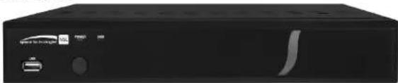
natural_image
Front view of a black electronic device with ports and indicator lights (no visible text or symbols)Figure 3.1.1. Desktop NSL Front panel
Table 3.1.1. Front LED and Port of NSL
| Name Description |
| POWER LED light is on when power is applied to the system. |
| HDD LED light is on when the system is recording video data. |
| USB Port This USB port for archiving footage into a USB device. (USB 2.0) |
3-2. Connectors

- Do not power this system on before all the connections are completed.
- Make sure all the connections are properly secured. Faulty connection may result in the system being damaged.
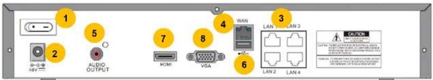
text_image
1 2 AUDIO OUTPUT 5 7 HDMI 8 VGA 4 WAN 3 LAN 1 LAN 3 6 LAN 2 LAN 4 CAUTION⑦ HDMI OUT: HDMI output port, Connector to the HDMI Monitor, (1280x720, and 1920x1080).
⑧ VGA OUT: Connector for VGA Monitor, Main Video Output.
3-3. Remote Control

text_image
Diagram of a remote control with numbered labels pointing to key buttons and function keysFigure 2.3.1. Remote Controller Button
① ID: To set the remote control ID.
② REC: To start and stop manual recording
③ SEARCH: To go to SEARCH menu.
④ F/ADV:
- During playback – To move the playback position 60 seconds forward
- During Pause – To move the playback position moves 1 frame forward
(5) FIREW
4. Setup NSL Series
The following sections detail the initial setup of NSL series.

Menu screen will close if user input is not received within 5 minutes.
4-0. Setup - Main Live Screen
To enter the setup menu, right click on the mouse and select setup from the submenu or press the setup button on the remote control.

text_image
CHS 252.306.28.15 Search Setup Order Boardset Super EZ Copy Enable Manual Record Ward Playback CHS 272.34.28 Add Tools Document Audio Magic Exercise PDS Search: Style Poster Software Manual Digital Deletion Camera Software System Software Expert Help System Lock General Software 172.25.28 2014 10/17 23 05 23 DC All HDD OwnerTable 4.0.1. Live Screen and Quick Operation Window
text_image
Login - Setup User ID admin Password 1 2 3 4 5 6 7 8 9 0 - - - q w e i ; y u i o p [ ]4-1. Setup - IP CAMERA
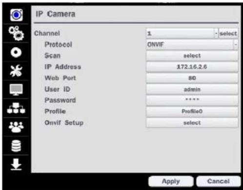
Press the SETUP button and enter the password. The IP Camera setup menu is displayed below.
text_image
IP Camera Channel 1 select Protocol ONVIF Scan select IP Address 172.16.2.6 Web Port 80 User ID adults Password ****** Profile Profile0 Onvif Setup select Apply CancelFigure 4.1.1. IP Camera mode setup screen
Table 4.1.1. Menu items in IP CAMERA mode setup
Item Description
CHANNEL To manually connect each camera, click on the "select" to get this window:
| Protocol | Scan | IP Address | Stream Port | Web Port | Others | |
| 1 | SPECO | 192.168.78.11 | 554 | 80 | ||
| 2 | SPECO | 172.16.2.11 | 554 | 80 |
text_image
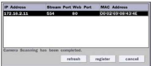
IP Address Stream Port Web Port MAC Address 172.16.2.11 554 80 00:02:69:08:43:4E Camera Scanning has been completed. refresh register cancelIP Address: Enter the address of IP camera to connect, or select from scanned list.
Stream Port: Enter the port number of IP camera to connect
Web Port: Enter the web port number of IP camera to connect
Others: Change the IP camera setting. Double click the empty box and then Log-In box will be pop-up. (Enter ID and PASSWORD of IP Camera)
Protocol Select the protocol of the IP Camera
Scan Automatic IP Camera search on the local network.
IP Address Set up IP camera address.
Port Set up the RTSP port of the IP Camera (default: 554)
Web Port Set up the web port of IP Camera (default: 80)
User ID Enter ID of IP camera
Password Enter the Password of IP Camera
ONVIF Setup Set up Video, Network and System of ONVIF IP Camera
4-1-1. Scan Menu
Scan for IP Cameras on network using SPECO/ONVIF/HIKVISION protocols.protocols

text_image
IP Cameras Channel 1-select Protocol ONVF Scan select IP Address 172.19.2.6 Web Port 80 User ID adults Password ****** Profile Profile0 Qnvif Setup select IP Camera Channel 1-select Protocol ONVF Scan select IP Address 172.19.2.6 Stream Port 554 Web Port 80 User ID adults Password ****** Setup select Apply Cancel Apply CancelFigure 4.1.2 IP Camera Setup Screen
text_image
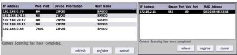
IP Address 192.168.0.79 192.168.78.14 192.168.78.12 192.168.78.11 192.168.0.88 Camera Scanning has been completed. refresh register cancel IP Address 172.16.2.11 554 80 00:02:59:08:43:4E MAC Address Camera Scanning has been completed. refresh register cancelFigure 4.1.3 Left Image using ONVIF Protocol Scan, Right Image using SPECO Protocol Scan
| Profile Name | Resolution | Frame Rate | Bit Rate | I-Frame Interval | H264 Profile |
| Profile0 | 1920 X 1080 | 30 | 2500 | 30 | Main |
| Profile1 | 640 X 360 | 30 | 1024 | 30 | Baseline |
4-1-2. ONVIF Setup Menu

text_image
IP Camera Channel 1 select Protocol ONVIF Scan select IP Address 172.16.2.6 Web Port 80 User ID admin Password ****** Profile ProfileQ Onvif Setup select Apply CancelFigure 4.1.2 IP CAMERA Setup Screen (ONVIF)
The NSL Series can search for IP Cameras that are conformant to ONVIF (Open Network Video Interface Forum). In order to search for ONVIF Cameras, the field associated with VENDOR has to be set to ONVIF. Click on the Box associated with SCAN to scan the networks for ONVIF Conformance cameras.
text_image
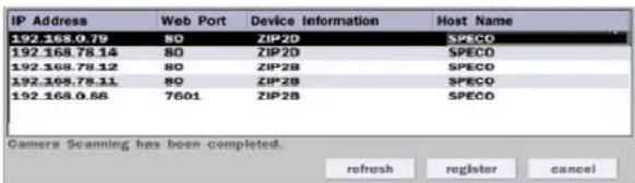
IP Address Web Port Device Information Host Name 192.168.0.79 80 ZIP2D SPECO 192.168.78.14 80 ZIP2D SPECO 192.168.78.12 80 ZIP2B SPECO 192.168.78.11 80 ZIP2B SPECO 192.168.0.88 7601 ZIP2B SPECO Camera Scanning has been completed. refresh register cancelFigure 4.1.4 ONVIF Camera Scan Window
④ Double click the listed profile to apply.
⑤ Enter ID and PASSWORD of IP CAM. Registration is .completed.

text_image
Video select Network select System select okFigure 4.1.6 ONVIF Setup Window
Under ONVIF Setup, the following can be viewed and changed: VIDEO, NETWORK, SYSTEM settings.
Menu Item Description
VIDEO Video, Encoder to view and change to audio settings.

text_image
Video Resolution 1920 X 1080 Framerate 30 Bitrate (Kbps) 2500 select Encoder I-Frame Interval 30 H.264 Profile Main Audio Codec Supports Only G.711 apply cancelNETWORK View and change Network settings.
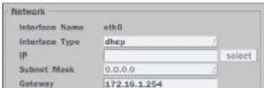
text_image
Network Interface Name eth0 Interface Type dhcp IP select Subnet Mask 0.0.0.0 Gateway 172.16.1.2544-2. Setup - SYSTEM
In the SETUP menu, select the SYSTEM tab. Then, the SYSTEM menu is displayed as pictured below. Navigate through the menu items or change the settings using the mouse or the remote control.

text_image
System Description select Language english Date Display Format yyyy/mm/dd Date & Time Setup select Client Access on NTP Setup off select e-Mail Setup off select Unit Name NVR System Restart select System Shutdown select EZ Setup select System Event Notification select Apply CancelFigure 4.2.1. SYSTEM Setup Screen
Table 4.2.1. Menu Items in SYSTEM Setup Screen
Item Description
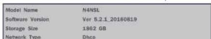
DESCRIPTION
Press the button to view the system information. (Software Version, Storage Size, Address, MAC Address and DDNS Status)
EU: Applies the EU daylight saving time.
- Select the GMT AREA using the mouse or the remote control.
- Set the time difference with the standard time using the mouse or the button.
OTHERS: If the time zone is neither USA nor EU, set the date and time of the daylight saving period.
- Select BEGIN or END.
Caution
- Do not set the start time to 23:00 for DLS.
- DLS cannot be applied if the date of BEGIN and END is the same.
CLIENT
Enable/Disable remote access through the network.
ACCESS
NTP
NTP (Network Time Protocol) which synchronizes the time of the computer systems over variable-latency data networks.
SETUP

text_image
Primary SNTP Server Pool.ntp.org select Secondary SNTP Server Time.nist.gov select Time Zone GMT -5:00 (Montreal/New York) Connection Mode time Connection Period 03:00 AM ok cancelPRIMARY SNTP SERVER: Input the address of the primary NTP time-server.
SECONDARY SNTP SERVER: Input the address of the secondary NTP time-server.
TIME ZONE: NTP synchronizes with GMT (Greenwich Mean Time) regardless of geography; user must select time difference from GMT.
CONNECTON MODE: Select the NTP time-server connection mode from TIME, INTERVAL, and ONCE.
Email Setup

text_image
Server Type MAIL Server mail Port 25 select Secure Option NONE mail ID select Password select mail To select mail From select test ok cancelSERVER TYPE: Select GMAIL, HOTMAIL, AOL, YAHOO or MANUAL)
MAIL SERVER: Enter the appropriate mail server information.
MAIL PORT: Assign Mail Port number.
SECURE OPTION: Select the secure mail server connection method. (SSL or TLS)
ID: Enter the appropriate mail server ID.
PASSWORD: Enter the appropriate mail server PASSWORD
MAIL TO: Enter the appropriate email address to enable sending e-mail reports using a virtual keyboard.
MAIL FROM: To set the email address sent to the destination host.
TEST : E-mail settings sent a test mail to the registered account
UNIT NAME Name the NSL (e.g. Factory)
This feature is to identify the name of the NSL under the same network.
SYSTEM
Restart the system
RESTART
SYSTEM
Shut down the system
HEALTH CHECK - OFF, ON
(Allows the user to set MAIL STATUS periodically) : DAILY or WEELY or MONTHLY

text_image
Period daily first sun 0 h ok cancelEVENT AND NOTIFICATION - OFF, ON
HEALTH CHECK / RESTART / SHUTDOWN / PANIC RECORD
- Enable Email Notification in the event a problem occurs.
MOTION DETECTION – Enable Email Notification when the camera detects motion.
1-2) Select Google Drive Cloud Archiving to 'Yes'

text_image
Google Drive Cloud Archiving off ok cancel1-3) Video clip will be save at Google Drive when 'Alarm-In' and 'Motion' triggered.
1-4) If the Google Drive Account is not activated then please sign it in through web setup first.
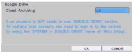
text_image
Google Drive Cloud Archiving on Your account is NOT ready to use 'GOOGLE DRIVE' service. To activate your account, you need to sign in to the service by using the 'SYSTEM -> GOOGLE DRIVE' menu of 'Web Setup'. ok cancel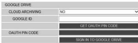
text_image
GOOGLE DRIVE CLOUD ARCHIVING NO GOOGLE ID GET OAUTH PIN CODE OAUTH PIN CODE SIGN IN TO GOOGLE DRIVE1-5) Set Video clip duration

: Use 'SpecoPlayer'
Notice – Support iOS from '1.5.8_150316', Android from
'3.2.2.7_150316'
How to use 'SNS'
- Notice : User have to make an Twitter account for DVR in order to follow the Twitter followers.
- DVR send event message to Twitter followers when Event Triggered.
1) How to set (Setup - System - System Event Notification - SNS)
1-1) Click "select" icon beside of SNS.
1-2) Enter the Twitter Account
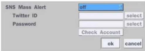
text_image
SNS Mass Alert off Twitter ID select Password select Check Account ok cancel1-3) Select the items that user want to receive the status message.
Select "yes"
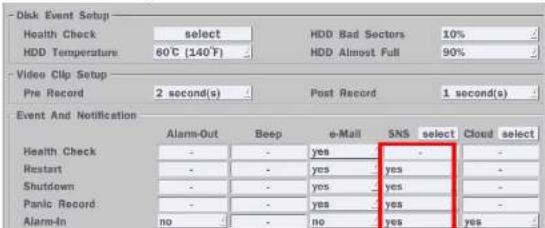
text_image
Disk Event Setup Health Check select HDD Bad Sectors 10% HDD Temperature 60°C [140°F] HDD Almost Full 90% Video Clip Setup Pre Record 2 second(s) Post Record 1 second(s) Event And Notification Alarm-Out Beep e-Mail SNS select Cloud select Health Check - - yes - - Restart - - yes - yes - Shutdown - - yes - yes - Panic Record - - yes - yes - Alarm-In no - no yes yes4-3. Setup - RECORD Mode
In the SETUP menu, select the RECORD tab. Then, the RECORD menu is displayed as pictured below. Navigate through the menu items or change the settings using the mouse or the remote control.
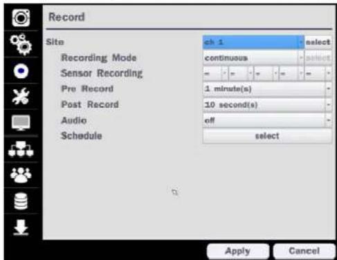
text_image
Record Site Recording Mode Sensor Recording Pre Record Post Record Audio Schedule ch 1 select continuous 1 minute(s) 10 second(s) off select Apply CancelFigure 4.3.1. RECORD Setup Screen
Table 4.3.1. Menu Items in RECORD Setup Screen
Menu Item Description
SITE Select a channel for applying the following settings using the mouse or the remote control. To change the values of all channels, take the following steps. Select the button "select" to change the values of all channels.
| Recording | Pre Record | Post Record | Audio | |
| all | motion | 1 min(s) | 10 sec(s) | off |
4-3-1. Recording Schedules
To setup a recording schedule, select SCHEDULE in the RECORD menu. Navigate through the menu items or change the settings using the mouse or the remote control.
Select CHANNEL > select NONE, CONTINUOUS or MOTION > Highlight area
To copy a schedule to a different channel, select the channel from the COPY SCHEDULE menu.
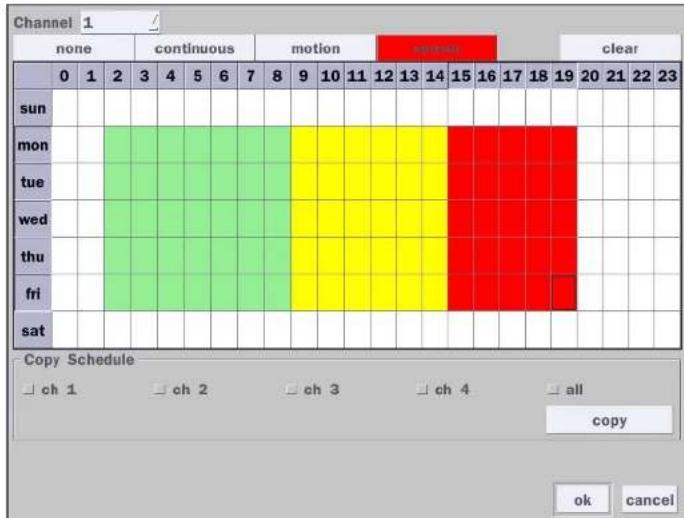
text_image
Channel 1 none continuous motion minutes clear 0 1 2 3 4 5 6 7 8 9 10 11 12 13 14 15 16 17 18 19 20 21 22 23 sun mon tue wed thu fri sat Copy Schedule ch 1-ch 2-ch 3-ch 4-all copy ok cancelFigure 4.3.2. Schedule Recording Setup Screen
• NONE: Disable recording during selected timeframe (Highlighted in White)
4-4. Setup - Device Mode
In the SETUP menu, select the DEVICE tab. Then, the device menu is displayed as pictured below. Navigate through the menu items or change the settings using the mouse or the remote control.
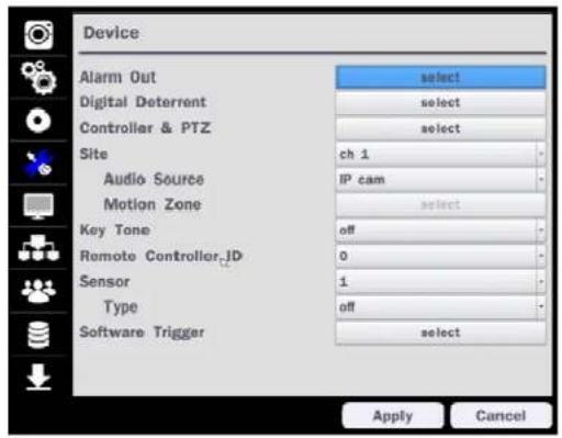
text_image
Device Alarm Out select Digital Deterrent select Controller & PTZ select Site ch 1 Audio Source IP cam Motion Zone select Key Tone off Remote Controller, ID 0 Sensor 1 Type off Software Trigger select Apply CancelFigure 4.4.1. DEVICE Setup Screen
Table 4.4.1. Menu Items in DEVICE Setup Screen
Item Description
Alarm Out / Only one Alarm-out is available.
Beep Duration Set beep dwell time from 5 to 60 seconds or infinite.
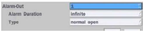
text_image
Alarm-Out 1 Alarm Duration infinite Type normal openSite Select the Audio Source and Motion Zone setup. (Full Zone or Partial)
Key Tone Enable/disable key tone from front panel usage.
Remote
Set the remote control ID.
Control ID
-
Select ID.
-
Input the remote control ID number.
-
An icon will indicate on the Live Screen if the remote control ID is synchronized.
The options are from 0 to 99
Sensor Select the type of each sensor.
Option is Off, Normal Open or Normal Close.
Software
Remote trigger channels. User can set the channels that want to make a sensor recording through remotely with Software record mode
Trigger
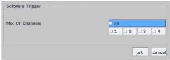
text_image
Software Trigger Mix Of Channels all 1 2 3 4 ok cancel4-4-1. Digital Deterrent
Trigger audio message via motion detection or sensor.

text_image
Import From USB select Export To USB select Record select Schedule select okFigure 4.4.2. Digital Deterrent setup screen
Table 4.4.2. Item for Digital Deterrent Setup Screen
| Item Description |
| IMPORT FROM USB Import up to 8 sound files from USB. |
| EXPORT TO USB Export the sound file to USB |
| RECORD Select a channel and set up the date and the duration.And, select the sound file to play. |
4-4-2. Alarm Box and Keyboard Controller Setup
To use Alarm box, user has to set "on" the below screen menu and in case of "on" on this menu, the alarm ports of NVR does not work.
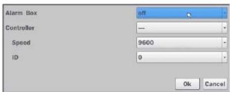
text_image
Alarm Box Controller Speed ID off - 9600 0 Ok CancelFigure 4.4.2.1. Alarm Box Setup Screen
Connect the Keyboard controller to the RS-485 port on the back of the chassis with CAT5 (or equivalent) cable.
① Connect the RS-485 cables of Keyboard controller to the RS-485 port on the rear panel.

text_image
4 3 2 1 G ■ SENSOR ■ ALARM RS485Figure 4.4.2.2. Sensor, Alarm and RS-485 Setup Screen
② Open the Controller sub menu by selecting the submenu button.

If FULL ZONE is selected, the motion zone grid screen is not displayed. Only set the level of sensitivity for MOTION SENSITIVITY.
FULL ZONE: The motion sensor is active on the whole screen.
PARTIAL ZONE: The motion sensor is active in the set detection frame.
Select the motion detection position using the mouse or the remote control. Then left click on the mouse or left click and drag the mouse pointer to select or deselect the area. Highlighted area indicates the partial motion detection zone. Press the ESC button or right click on the mouse to return to the previous menu.

natural_image
Interior view of a modern kitchen or laboratory with glass partitions and wooden flooring (no visible text or symbols)Figure 4.4.4. Motion Zone Grid Screen
4-5. Setup - DISPLAY Mode
In the SETUP menu, select the DISPLAY tab. Then, the DISPLAY menu is displayed as pictured below. Navigate through the menu items or change the settings using the mouse or the remote control. To return to the previous setup menu screen, press the ESC button.
Table 4.5.1. Menu Items in DISPLAY Setup Screen
| Item Description | |
| OSD Enable/Disable on-screen-display.(Channel Name, Video Loss, Status Bar / Icon) | |
| OSD CONTRAST Set the visibility level of the On Screen Display (OSD) (0~100) | |
| MAIN MONITOR | Enable/Disable sequential display of video in full screen mode. |
| SEQUENCE | |
| SEQUENCE | Set the dwell time of each, |
| DWELL TIME | single channel display in sequential display mode (3~60 seconds) |
| SITE Select a channel to apply the name and covert settings change using the mouse or the remote control.Select a channel to apply the following settings using the mouse. | |
| NAME | Set the channel name. Press the right square button and set the channel name and select OK using the mouse.The name can be made up to 36 characters. |
| COVERT | Enable/disable display of the specified video channel in live display. |
| VIDEO OUTPUT | Select 1280x720 or 1920x1080. |
4-6. Setup - NETWORK Mode
Select the NETWORK tab. Then, the network menu is displayed as pictured below. Navigate through the menu items or change the settings using the mouse or the remote control.
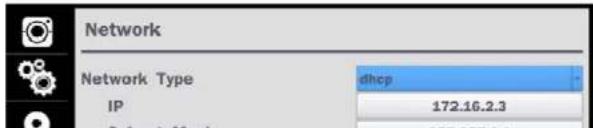
text_image
Network Network Type IP dhcp 172.16.2.3Table 4.6.1. Menu Items in NETWORK Setup Screen
| Item Description | |
| NETWORK TYPE DHCP: ZS will automatically retrieve an IP address. STATIC: Network information must be manually configured. | |
| IP Enter IP address that is assigned | |
| SUBNET MASK Enter Subnet Mask that is assigned | |
| GATEWAY Enter Gateway that is assigned. | |
| DNS (PRIMARY) Enter Primary DNS address that is assigned | |
| DNS (SECONDARY) Enter Secondary DNS address that is assigned | |
| DDNS | Dynamic Domain Name System (DDNS) allows a DNS name to be constantly synchronized with a dynamic IP address. In other words, it allows using a dynamic IP address to be associated with a static domain name so others can connect to it by the static name. Enable/disable using domain name address through DDNS server. |
| Network Video Port Enter the port number. | |
| Network Audio Port Display the network audio port (NETWORK PORT + 1). | |
| Web Port Enter the port number for connection using web. | |
4-6-1. Network Types
4-6-1-1. DHCP
An IP address is automatically assigned by the DHCP server, which automatically assigns the IP address and other parameters to new devices.
4-6-1-2. STATIC
IP address, Subnet Mask, Gateway, and DNS are manually assigned by the user.
• IP ADDRESS: The fixed IP address of the NSL unit.
CUDNET MACI: The subnet mask for the LAN
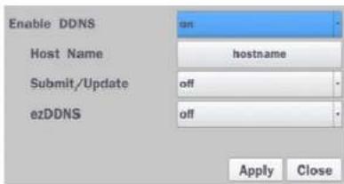
text_image
Enable DDNS Host Name Submit/Update ezDDNS on: hostname off off Apply CloseFigure 4.6.2. NETWORK Setup Screen - DDNS
Table 4.6.2. DDNS
| Item Description | |
| ENABLE DDNS | Turn DDNS on/off |
| HOST NAME | This item allows the user to setup a domain name manually, using virtual keyboard displays as shown. |
| SUBMIT/UPDATE | When manual host name input is done, move the cursor to this item and select ON to submit the settings. |
| ezDDNS | Enable/disable ezDDNS to register the host name automatically. |
4-6-3. Network Port and Web Port
Connecting NSL through a common IP sharing device, each NSL must be assigned a unique TCP port number for access from outside the LAN. This port number is displayed on NETWORK>NETWORK PORT Setup MENU.

NOTE:
If you access the NSL only within the same LAN, the TCP port number does not need to be changed.
Network access beyond a router
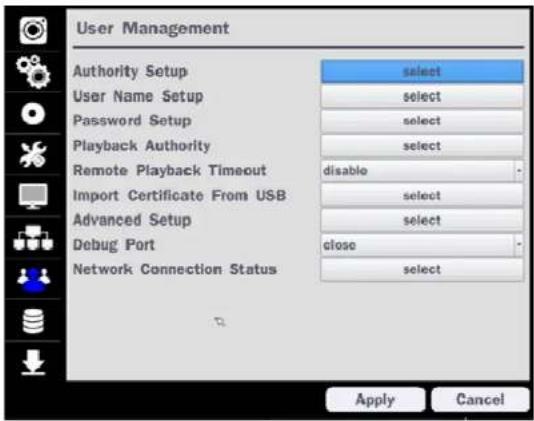
text_image
User Management Authority Setup select User Name Setup select Password Setup select Playback Authority select Remote Playback Timeout disable Import Certificate From USB select Advanced Setup select Debug Port close Network Connection Status select Apply CancelFigure 4.7.1. USER MANAGEMENT Setup Screen
Table 4.7.1. Menu Items in USER MANAGEMENT Setup Screen
Item Description
| AUTHORITY | Only the Admin will have access to the menu. | |||||||
| SETUP | PASSWORD CHECK: Select the Checkbox to enable the functions or leave the Checkbox blank to disable the functions.SETUP: Enable/Disable of access to SetupPB: Enable/Disable of access to PlaybackREC OFF: Enable/Disable of manual RecordNETWORK: Enable/Disable of access to Network | |||||||
| ADMIN, USER1, USER2, USER3, USER4, USER5, USER6, USER7, USER8, USER9:Selected Checkbox: The user can access the function.Blank Checkbox: The user cannot access the function. | ||||||||
| USER NAMESETUP | Change the name of USER1, USER2, USER3, USER4, USER5, USER6, USER7, USER8, and USER9. Click "select" and change the user name on the virtual keyboard. | |||||||
| PASSWORDSETUP | Passwords can be changed for ADMIN, USER1, USER2, USER3 USER4, USER5, USER6, USER7, USER8, and USER9. Select USER PASSWORD using the mouse or the remote control. Select username and enter the current password. And, enter a new password, enter the same password again to confirm and select OK. Then the message "PASSWORD CHANGED" is displayed.The factory default password is 1111.It is highly recommended to assign a new password to protect the system. | |||||||
| PLAYBACKAUTHORITY | Set authority level of playback on each user.Checked box: authorized to playback. Blank check box: no authority. | |||||||
| 1 | 2 | 3 | 4 | 5 | 6 | 7 | 8 | |
| ADMIN | × | × | × | × | × | × | × | |
| USER1 | = | = | = | = | = | = | = | |
| USER2 | × | × | × | × | × | × | × | |
| USER3 | × | × | × | × | × | × | × | |
| USER4 | × | × | × | × | × | × | × | |
| USERS | × | × | × | × | × | × | × | |
| USERS | × | × | × | × | × | × | × | |
| USER7 | × | × | × | × | × | × | × | |
| USER8 | × | × | × | × | × | × | × | |
| USER9 | × | × | × | × | × | × | × | |
REMOTE
Disconnect the remote playback after the specific time (Disable 5min 10min 15min
Network
Connection
Status
Shows the current network connection status (User, IP Address, Date / Time). And do disconnect the user's network connection to click 'disconnect' button.
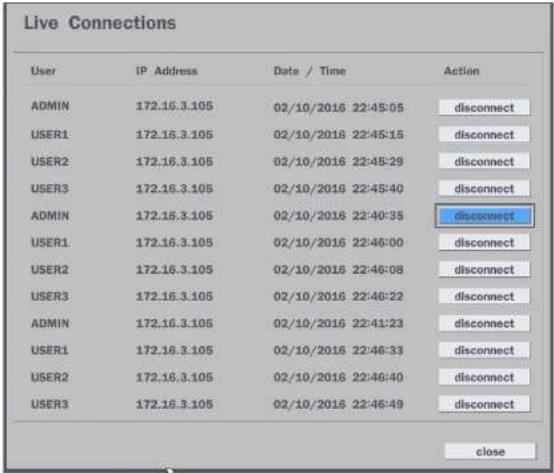
text_image
Live Connections User IP Address Data / Time Action ADMIN 172.16.3.105 02/10/2016 22:45:05 disconnect USER1 172.16.3.105 02/10/2016 22:45:15 disconnect USER2 172.16.3.105 02/10/2016 22:45:29 disconnect USER3 172.16.3.105 02/10/2016 22:45:40 disconnect ADMIN 172.16.3.105 02/10/2016 22:40:35 disconnect USER1 172.16.3.105 02/10/2016 22:46:00 disconnect USER2 172.16.3.105 02/10/2016 22:46:08 disconnect USER3 172.16.3.105 02/10/2016 22:46:22 disconnect ADMIN 172.16.3.105 02/10/2016 22:41:23 disconnect USER1 172.16.3.105 02/10/2016 22:46:33 disconnect USER2 172.16.3.105 02/10/2016 22:46:40 disconnect USER3 172.16.3.105 02/10/2016 22:46:49 disconnect close4-8. Setup - STORAGE Mode
In the SETUP menu, select the STORAGE tab. Then, the STORAGE menu is displayed as pictured below.
Navigate through the menu items or change the settings using the mouse or the remote control.

Storage
Overwrite
an
1.1
Table 4.8.1. Menu Items in STORAGE Setup Screen
| Item Description | |
| OVERWRITE | When enabled, the NSL will continue recording and overwrite the oldest existing recorded data once the hard drive is full. When disabled, recording will stop once the hard drive is full. |
| DISK FORMAT | Once clicked, the user will have to confirm to format the Hard Drive.After confirming, the NSL will reboot, and the format sequence will load.The format sequence allows user to select which HDDs to format.Caution: It is recommended to archive any data that you may need in the future before formatting the hard drive. |
DISK INFO Hard drive information. Displays the following information:
| HDD 1 | Model Name | Temperature | Health (Good/Normal/Batch) | Reallocated Sectors | Current Pending Sectors | Uncorrectable Sectors | Spin Retry Count | |
| WDC WDOSEURG G3SPKYO | 40 °C (104 °F) | Good | ||||||
| HDD 2 | HDD 1 | 0 | 0 | 0 | 0 | |||
| HDD 3 | HDD 2 | |||||||
| HDD 4 | HDD 3 | |||||||
| HDD 5 | HDD 4 | |||||||
| HDD 6 | HDD 5 | |||||||
| HDD 7 | HDD 6 | |||||||
| HDD 8 | HDD 7 | |||||||
| HDD 8 | ||||||||
RECORDING Enable recording limit: The amount of data recorded in HDD will be limited to the LIMIT most recent number of days as set by "RECORDING LIMIT DAYS".
Disable recording limit: When OVERWRITE is ON, DVR will continue to record when HDD is full and overwrite older data. When OVERWRITE is OFF, DVR will stop recording when the HDD is full.
| RECORDING | Set the recording limit days. (1- 90 days) |
| LIMIT DAYS | If the RECORDING LIMIT DAYS are set to 1, the data will be overwritten after 24 hours |
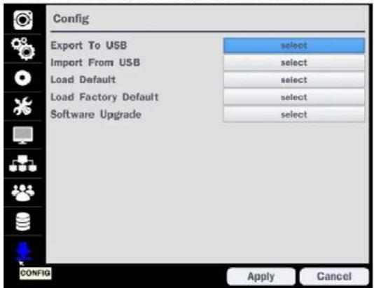
4-9. Setup - CONFIG Mode
In the SETUP menu, select the CONFIG tab. Then, the configuration menu is displayed as pictured below.
Navigate through the menu items or change the settings using the mouse or the remote control.
text_image
Config Export To USB select Import From USB select Load Default select Load Factory Default select Software Upgrade select CONFIG Apply CancelFigure 4.9.1. CONFIGURATION Setup Screen
Table 4.9.1. CONFIGURATION Setup
| Item Description | |
| EXPORT TO USB | User can save the current configuration settings of the NSL to a USB flash drive. Plug in the USB flash on the front panel and press the button to start the export process. |
| IMPORT FROM USB | User can upload the configuration of the NSL to another NSL using the USB Flash drive. Plug in the USB flash drive on the front panel and press the |
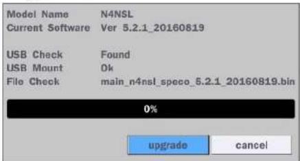
4-9-1. Firmware Upgrade
- Create a new folder named "upgrade" in the USB flash drive root directory.
- Create sub-folder for each model under "upgrade" folder and copy each firmware.
• N4NSL: main_n4nsl_speco_.*.*_201****
- N8NSL: main_n8nsl_speco_ * * * 201****

text_image
C:\Users\12.03.04\MyFile Organize Search files Name Date modified Type Size Documents Files 12/15/2001.03.04 File1 12/15/2001.03.04 File2 12/14/2001.10.04 File3 3.4mms- Plug in the USB flash drive on the rear panel.
- Navigate to CONFIG menu of SETUP.
- Select SOFTWARE UPGRADE.
- Follow the procedure from Figure 4.9.2 to Figure 4.9.4.

text_image
Model Name N4NSL Current Software Ver 5.2.1_20160819 0% scan cancelFigure 4.9.2
text_image
Model Name N4NSL Current Software Ver 5.2.1_20160819 USB Check Found USB Mount Ok File Check main_n4nsl_speco_5.2.1_20160819.bin 0% upgrade cancelFigure 4.9.3

5. Live, Search and Playback
5-1. Live View
In the Live screen, video inputs from the cameras are displayed as they are configured in the Display Setup screen. Various On-Screen Display (OSD) symbols, which indicate the status of the NSL, are described in Table 5.1.1.

text_image
CH4 192.168.78.11 Search Setup Display Snapshot Super EZ Copy Double Manual Record Instant Playback E2 Setup Document Audio Mato Camera PTZ Double Main Window Sequence Manual Digital Document Camera Information System Information Export Help System Lock System Shutdown 172.16.2.6 172.16.2.12 2016.10.07 21:09:23 RC All HQF Over TimeFigure 5.1.1. Live Screen and Quick Operation Window
Table 5.1.1. Status Indicator Icons in Live Viewing Screen
Icon Description

Indicates the NSI is locked
05/15/2013 11:15:42
Displays the current date and time.
RC: ALL Remote control ID display. If a remote ID is not set, the message "ALL" is displayed.

15%
Displays the amount of recording on the hard disk from 0-99%.

Indicates that HDD is recycled.

Continuous recording in progress.

Manual recording in progress. To set the Manual recording mode, press the Record button on the front panel.

Motion alarm recording in progress.

Sensor recording in progress.
Right click the mouse, and the quick operation window will be displayed as below.
| EZ Setup | ||
| Connect | ||
| Audio Mute | V | |
| Camera PTZ | ||
| Enable Main Monitor Sequence | ||
| Disable Alarm Out | ||
| Manual Digital Deterrent | ||
| Camera Information | ||
| System Information | ||
| Export Help | ||
| Playback | Search Setup Display Snapshot Super EZ Copy Enable Manual Record Instant Playback Advanced Menu | Go Back To 10 Seconds Go Back To 20 Seconds Go Back To 30 Seconds Go Back To 60 Seconds |
| Recommended to be used with record mode s | ||
Advanced Menu
| EZ Setup | Select this option to start EZ Setup Wizard. |
| Connect | Select this option to disconnect/connect from IP Camera. |
| Audio Mute | Select this option to mute audio on all channels. |
| Camera PTZ | Pop up the PTZ user interface. |
| Enable Main Monitor Sequence | Sequence button. Click this button to use a sequence function. |
| Disable Alarm Out | Click this button to enable/disable Alarm outputs |
| Manual Digital Deterrent | Select this option to manually trigger any of the saved Digital Deterrent messages. |
| Camera | Press the button to view the record setting of a selected channel. |
| Model Name | N4NSL |
| Software Version | Ver 5.2.1_20160819 |
| Storage Size | 1862 GB |
| Network Type | Dhcp |
| IP Address | 172.16.2.7 |
| MAC Address | 00:02:69:0A:1F:0C |
| DDNS Status | Ready - n4nsl_0a1f0c |
| Unit Name | NVR |
| Remote Controller ID | 0 |
Export Help Displays window with instructions for exporting video.
System Locks the system from unauthorized user access.
Lock
System Select this option to shutdown system.
Shutdown
5-1-1. PTZ Control
Table 5.1.3. Menu Items in PTZ Control Window
| Image Item Description | ||
| INITIALIZE Initialize the PTZ settings of the selected camera | ||
| PAN/TILT | Select PAN/TILT using the ▲▼◀ and ▶button, then press SEL. Adjust the tilt (UP/DOWN)/pan (LEFT/RIGHT) position using the ▲▼◀and ▶buttons. | |
| ZOOM/FOCUS | Select ZOM/FOCUS using the▲▼◀ and ▶buttons, then press SEL. Adjust the zoom (UP/DOWN)/ focus (LEFT/RIGHT)position using the ▲▼◀ and ▶ buttons. | |
| OSD | Select OSD to enter the menu. Control keys are Right, Left, UP, Down, Select, Far (REW KEY), and Near (FF KEY). Press the ESC button to return to the previous menu. Press the PTZ button to close the OSD menu. | |
| AUTOSCAN | Press the right key(▶) to start auto scan. Press the left key (◀) to stop auto scan. | |
| PRESET | Select PRESET, then press the left key(◀). A number input window will appear. Set the number (3digits) using the number key, then press the SEL to confirm the preset number for the current position. Press the right key (▶) and enter the number (3digits) to go to the preset position. | |
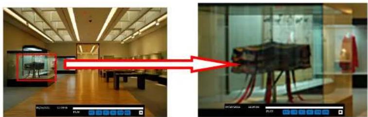
5-2. Digital Zoom in Live and Playback Screen
NSL series supports Digital Zoom feature during live and playback mode.
- Double click the target channel.

text_image
CH 2 CH5 CH 6- Click the left button of the mouse and drag to make rectangular shape.
natural_image
Two interior views of a modern exhibition space: one showing a display case with a red arrow pointing to a museum exhibit (no visible text or symbols)5-3. SEARCH Screen
To enter the search screen menu, select SEARCH menu on the screen using the mouse or press SEARCH icon on live screen.

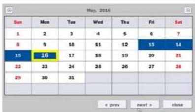
5-3-1. EZSearch
The EZSearch window is used to find stored video with ease using the thumb nail playback screen.
text_image
May, 2016 Sun Mon Tue Wed Thu Fri Sat 1 2 3 -4 5 6 7 8 9 10 11 12 13 14 15 16 17 18 19 20 21 22 23 24 25 26 27 28 29 30 31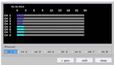
text_image
05/30/2016 CH 1 CH 2 CH 3 CH 4 CH 5 CH 6 CH 7 CH 8 Channel ch 1 ch 2 ch 3 ch 4 ch 5 ch 6 ch 7 ch 8 < prev play closeFigure 5.3.3. Channel Selection Screen
Figure 5.3.2. Calendar Screen
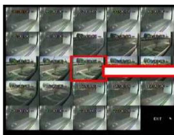
text_image
Grid of surveillance cameras with a red overlay highlighting a specific camera area, likely from an outdoor surveillance system.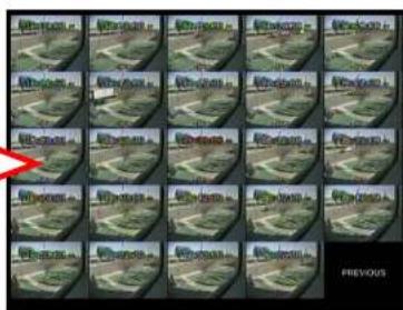
text_image
PreviousFigure 5.3.5. Minute Thumbnail Screen
Figure 5.3.4. 24 Hourly Thumbnail Screen
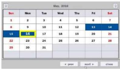
5-3-2. Smart Search
The Smart Search window is used to find stored video with motion detected screen.
text_image
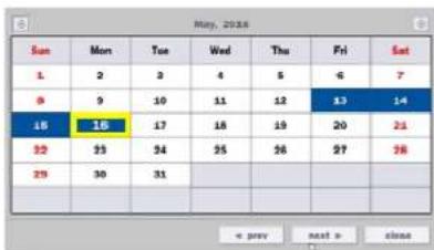
May, 2019 Sun Mon Tue Wed Thu Fri Sat 1 2 3 4 5 6 7 8 9 10 11 12 13 14 15 16 17 18 19 20 21 22 23 24 25 26 27 28 29 30 31 < prev next > closeFigure 5.3.7. Calendar Screen

text_image
05/18/2016 0 3 6 9 12 15 18 21 24 CH 1 CH 2 CH 3 CH 4 CH 5 CH 6 CH 7 CH 8 Channel 0 ch 1 ch 2 ch 3 ch 4 ch 5 ch 6 ch 7 ch 8 < prev play closeFigure 5.3.8. Channel Selection Screen

text_image
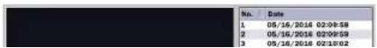
08/18/2016 00:00:30 Start 5 16 2016 2 10 0 End 5 16 2016 2 10 0 Zone partial select Name/Divite: export e-mail Interval 1 sec No. Date start search closeFigure 5.3.9 Full Zone Screen
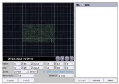
text_image
08/16/2016 00:00:00 Next 9 14 2016 2 10 0 End 5 16 2016 2 20 0 Zone partial select to all, 0.1.1.000.000 Residuals 0 Interval 1.000 agent email Instant search closeFigure 5.3.10. Partial Zone Screen
5-3-3. Time Line Search
The CALENDAR Search window is used to find the stored video by using the time line bar.
text_image
May, 2023 Sun Mon Tue Wed Thu Fri Sat 1 2 3 4 5 6 7 8 9 10 11 12 13 14 15 16 17 18 19 20 21 22 23 24 25 26 27 28 29 30 31 =< prey> salt > close
text_image
05/16/2018 05:42:00 CH 1 CH 2 CH 3 CH 4 CH 5 CH 6 CH 7 CH 8 Channel • all ch 1 ch 2 ch 3 ch 4 ch 5 ch 6 ch 7 ch 8 + prev play closeFigure 5.3.12. Calendar Screen
Figure 5.3.13. Time-Line Search Screen
When the Timeline menu is selected, the user can see a calendar, which displays recorded dates with highlights. Select a specific date and time. Click and drag the red time indicator bar to the desired hour. User can select a specific minutes using a button in the above red box. Press the PLAY button after selecting the specific time. Press the PREV to return to the SEARCH window.
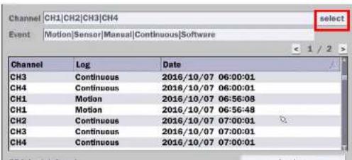
5-3-4. Event Search
The Event Search window is used to find stored video.
text_image
Channel CH1|CH2|CH3|CH4 select Event Motion|Sensor|Manual|Continuous|Software < 1 / 2 > Channel Log Date CH3 Continuous 2016/10/07 06:00:01 CH4 Continuous 2016/10/07 06:00:01 CH1 Motion 2016/10/07 06:56:08 CH1 Motion 2016/10/07 06:56:48 CH2 Continuous 2016/10/07 07:00:01 CH3 Continuous 2016/10/07 07:00:01 CH4 Continuous 2016/10/07 07:00:015-3-5. Go To First Time
User can access from the oldest recorded data on the NSL hard drive by selecting GO TO FIRST TIME on the SEARCH window. Press the PREV to return to the SEARCH window.
5-3-6. Go To Last Time
User can access from the last minute recorded data on the NSL hard drive by selecting GO TO LAST TME on the SEARCH window. Press the PREV to return to the SEARCH window.
5-3-7. Go To Specific Time
User can search for video data from a specific instance by setting the date and time in the GO TO SPECIFIC TIME menu. Use the mouse or the remote control to change the date and time value and press the PLAY button after setting. If there is no video data in the set date and time, No Data Exist message displays.
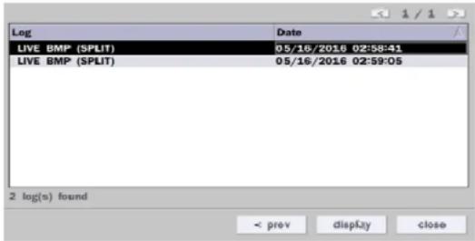
5-3-8. Archive List
The ARCHIVE Search window is used to find previously stored video or images.
text_image
Log Date LIVE BMP (SPLIT) 05/16/2016 02:58:41 LIVE BMP (SPLIT) 05/16/2016 02:59:05 2 log(s) found < prev display closeFigure 5.3.16. Archive Search Screen
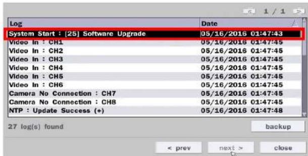
text_image
Log System Start : [25] Software Upgrade 05/16/2016 01:47:43 Video In : CH1 05/16/2016 01:47:45 Video In : CH2 05/16/2016 01:47:45 Video In : CH3 05/16/2016 01:47:45 Video In : CH4 05/16/2016 01:47:45 Video In : CH5 05/16/2016 01:47:45 Video In : CH6 05/16/2016 01:47:45 Camera No Connection : CH7 05/16/2016 01:47:45 Camera No Connection : CH8 05/16/2016 01:47:45 NTP : Update Success (+) 05/16/2016 01:47:48 27 log(s) found backup < prev next > closeFigure 5.3.12. Log List Screen
When the Log menu is selected, the user can see a calendar, which has a log data. Select a specific date and press NEXT button, and then the log data will be displayed. Press the SAVE button to save the data and then the data is saved as a text file format.
5-4. Play Mode
During playback of a recorded event, the mode changes from SEARCH to PLAY. While in PLAY mode, user may return to the SEARCH screen by pressing the X button on the status bar.

text_image
CH1 CH2 CH3 No Data CH4 CH5 CH6 No DataTable 5.4.1. Button Functions in PLAY Mode
Button Description

- 2x, 4x, 8x, 16x, 32x speeds at 2x2 screen display mode.
- 2x, 4x, 8x, 16x speeds at 3x3 screen display mode.
- 2x, 4x, 8x speeds at the 4x4 screen display mode.
- Single Channel backward playback speed 1x, 2x, 4x, 8x, 16x, 32x, 64x

Jump/Step backward. The playback position moves 60 seconds backward.

Press to play or pause recorded video.

Jump/Step forward. Playback position moves 60 seconds forward.

- 2x, 4x, 8x, 16x, 32x speeds at 2x2 screen display mode
- 2x, 4x, 8x, 16x speeds at 3x3 screen display mode.
- 2x, 4x, 8x speeds at the 4x4 screen display mode.
- Single Channel forward playback speed 1x, 2x, 4x, 8x, 16x, 32x, 64x

Slow Mode play. Forward playback speed x1/4, x1/2

Press to backup the video.

EZCopy button.

Return to the previous menu screen, search window, or exit from the Menu.
6. Back Up
6-1. Still Image Backup onto USB Flash Drive
Still images can be captured and archived onto a USB flash drive or an USB external hard drive in live mode or while playing back recorded video.
- Select a specific channel, which wants to back up on live screen.
- When you press SNAPSHOT button on Quick operation window, the media selection window screen will display.

text_image
Search Setup Display Snapshot Super EZ Copy Enable Manual Record Instant Playback Advanced Menu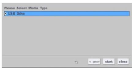
text_image
Please Select Media Type • USB Drive < prev start close- Once you press START button, the system will capture a still image and archive onto a USB flash drive.

NOTICE
USB Flash Drive must be in FAT32 file format.
6-2. Video Backup onto USB Flash Drive during playback
Video can be captured and archived onto the USB flash drive or a hard drive while playing back the

text_image
Please Select Media Type USB Drive < prev start close- Once you select the channel and duration, the system will start to archive the data to the USB drive.

text_image
EZCopy 2016/05/16 04:51:53 - 2016/05/16 04:52:00 □ all □ ch 1 □ ch 2 □ ch 3 □ ch 4 □ ch 5 □ ch 6 □ ch 7 □ ch 8 Free Capacity Required Capacity calculation < prev start close- The following image shows the progress of archiving the data.
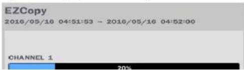
text_image
EZCopy 2016/05/16 04:51:53 - 2016/05/16 04:52:00 CHANNEL 1 20%6-2. EZCopy: Video Backup onto USB Flash Drive during playback
Using EZCopy feature, Video can be easily archived onto the USB flash drive or a hard drive.
In playback mode, press the EZ COPY button to launch the backup function.
- Press EZCOPY button on the selected channel or all channels.

text_image
User interface toolbar with playback buttons and a cursor pointing to the 'EZ' button- Then, EZCOPY START time will display.

text_image
2011/10/10 03:33:- Move time bar cursor to the time of end of backup and press EZCOPY button. Then, EZCOPY STOP time will display.

text_image
2011/10/10 04:44:- EZCOPY window will display. The NSL will ask whether to archive a Still Image, a NSF or AVI.
The stored data in the hard drive can be found in the ARCHIVE list in the SEARCH window. User can back up still images or video into the storage device from the ARCHIVE list.
- Select the date to begin searching and navigate through the days using the mouse or the remote control.
- Once you have selected the date, press the NEXT button to open the list of stored data.
- Use the mouse or the remote control to scroll through the archive list.
- Select a list of stored events in the archive list.
- Once the desired event has been selected, press the DISPLAY button to view the still image or the first frame of the selected video.
- Press the BACKUP button to launch the archiving function in playback mode.
- Press the CLOSE button to return to the SEARCH window.

text_image
Log Date LIVE BMP (SPLIT) 05/16/2016 02:58:41 LIVE BMP (SPLIT) 05/16/2016 02:59:05 LIVE BMP (SPLIT) 05/16/2016 04:51:55 CH1 AV(1 min) 05/16/2016 04:59:05 CH1 AV(0 min) 05/16/2016 05:04:21 LIVE BMP (SPLIT) 05/16/2016 05:11:31 CH1 AV(0 min) 05/16/2016 05:34:25 7 log(x) found Backup CH 1 AV(1 min) Media USB 05/16/2016 04:51:51 < 4 / 7 > backup < prev display close backup close- Please install the NSL copies "HDPlayer" folder on USB flash drive with the video.

text_image
100.jpg 2.00- Otherwise, the video and time stamp over video can't be properly playback and displayed on Window Media Player™.
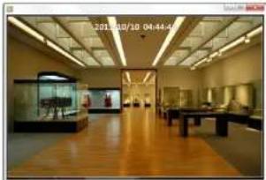
natural_image
Interior view of a museum or exhibition hall with wooden flooring, display cases, and ceiling lighting (no visible text or signage)
Timestamp On AVI. The subtitle is embedded to the video clip file.
subtitle is embedded to the AVI file. To display a subtitle, user should install a special filter called "UMSDecoderFilter".
6-5-2. NSF Format

NSF format: NSF format video can be played back using the HD player that the NSL copies to "NSPlayer" folder on USB flash drive with video. Use the mouse scroll to use digital zoom in and out feature.
7. Network Access Using the Multi-Sites Network Viewer
7-1. Overview
The SpecoTech Multi Client is a multiple site monitoring client software with; video, audio, and alarm signals from the NSL over the network. The SpecoTech Multi Client does not limit the number of NSL units to register.
The program displays up to 8 NSL units and supports dual monitors.
By attaching a microphone and speaker system to devices on site, the user may make bi-directional audio communication over the network.
7-2. PC Requirements
Minimum PC Requirements
| CPU Intel Core | 3 |
| 1.8Ghz | |
| Memory 2GB DDR2 | |
| VGA 512MB | |
| Resolution 1280x720 | |
| Disk Space | 1GB |
| OS | Windows 2000, XP Professional, XP Home, Vista, 7 and 10 (NOTE: Not all versions of Vista and 7 are supported) |
| Network 10/100Base T | |
| Others | Direct X 9.0c or Higher |
Recommended PC Requirements
| CPU Intel Core i5 |
7-3. Installation of the Program
- Insert the provided CD in the CD drive and double-click "SpecoTech Multi Client (XXXX).exe"

- Select a destination folder and click "Next".
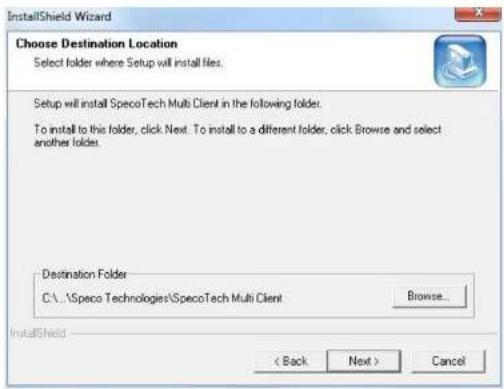
text_image
InstallShield Wizard Choose Destination Location Select folder where Setup will install files. Setup will install SpecoTech Multi Client in the following folder. To install to this folder, click Next. To install to a different folder, click Browse and select another folder. Destination Folder C:\...\Speco Technologies\SpecoTech Multi Client Browse... < Back Next > Cancel- Select the program folder and click "Next".
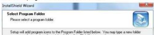
text_image
InstallShield Wizard Select Program Folder Please select a program folder. Setup will add program icons to the Program Folder listed below. You may type a new folder7-4. Live Window
When installation is completed, double click the "SpecoTech Multi Client" icon on your desktop to start the program.
7-4-1. Main User Interface
text_image
SPECO Multi Client Ver 3.1.2.57-4-2. Control Buttons
| Button Description | |
 LOCAL PLAYBACK LOCAL PLAYBACK | Click this icon to run a playback window to search and play videos that are recorded in the local PC. |
 | SETUP | Click this icon to setup configuration of MULTI CLIENT. |
 | CAPTURE | Click this icon to capture a still image. |
 | EVENT LIST | Opens list of events logged by Multi Client. |
 | PAUSE | Click this icon to play/pause live video. |
 | ALARM ON | Click this icon to turn on/off alarm outputs. |
 | RECORD ON | Enable or disable recording of live video to local disk, which has set in setup menu. |
 | AUDIO | Use the volume control bar to set the audio level. |
 | MIC | Use the microphone volume control bar to set the micro phone level. |
 | PRESET/TOUR/SCAN/MENU | User can control PRESET/TOUR/SCAN/MENU |
 | [IMAGE] | Time select the number of data channels and 3 channels, of highlyghted site. |
| [000] | [IMAGE] | Time select the number of data channels (in N, input A, output S, output T, output S) main display screen. |
) on
7-5. Search and Playback Window
7-5-1. Main User Interface
7-5-2. Main Control Panel
| Button Description | |
 LOCAL PLAYBACK LOCAL PLAYBACK | Click this icon to run a playback window to search and play videos that are recorded in the local PC. |
 REMOTE PLAYBACK REMOTE PLAYBACK | Click this icon to run a playback window to search and play videos that are recorded in the remote NS. |
 | THUMBNAIL REFRESH: Click this icon to refresh and renew thumbnail image of the connected sites.SITE ADDITION: Click this icon to open 'Site Addition' window.SITE DELETE: Click this icon to delete site from the index window, after disconnect a site.NET FINDER: Select the site from the index window and click this icon to modify the information of specific site. |
 CONNECT CONNECT | Click this icon to connect the selected site/sites. |
 DISCONNECT DISCONNECT | Click this icon to disconnect the selected site/sites. |
 ETUP ETUP | Click this icon to setup configuration of SpecoTech Multi Client. |
 CAPTURE CAPTURE | Click this icon to capture a still image. |
 | To select the channel to playback. | |
 | The calendar shows dates with recorded video in color. | |
 | To display the recorded data of selected channel or all channels on a time line scale. | |
 | To change a timeline scale from 24 hours to 60 minutes.The timeline shows recorded data in color on the bar. You can adjust the timeline scale and move it to the time you wish to playback. Then click the play icon to display the recorded video. | |
 | Playback buttons. | |
 | Thumbnail search over the network.- List the thumbnail 24images from 00:00 to 23:00.- Select one of 24 images every 150sec for an hour.- Then play the tile* Click the "PREVIOUS" button to go the previous step. | |
 | Digital Zoom Window in Live and Playback. (Only available in Single Channel Viewing) | |
7-6. Setup of SpecoTech Multi Client
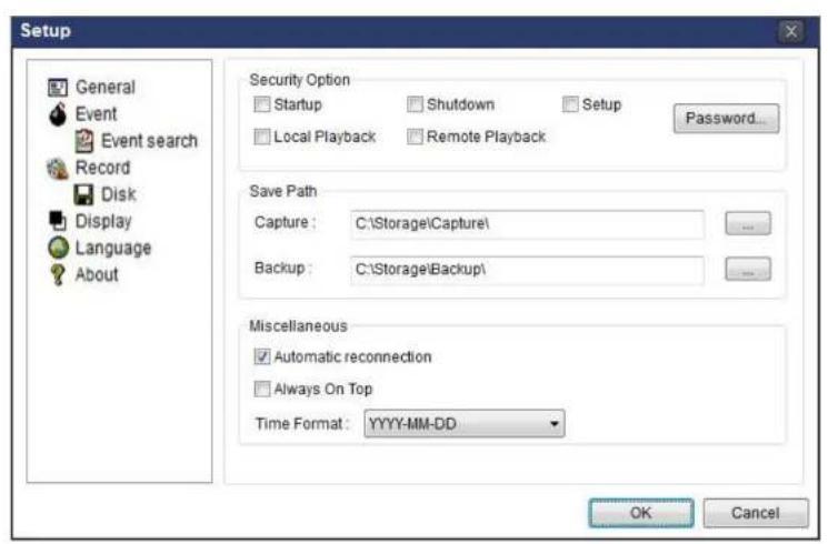
text_image
Setup General Event Event search Record Disk Display Language About Security Option Startup Shutdown Setup Local Playback Remote Playback Password... Save Path Capture: C:\Storage\Capture\ Backup: C:\Storage\Backup\ Miscellaneous Automatic reconnection Always On Top Time Format: YYYY-MM-DD OK Cancel7-6-2. Event
Event log can be archived and searched.
Event Log: Specify the location to save event logs and select event to archive.
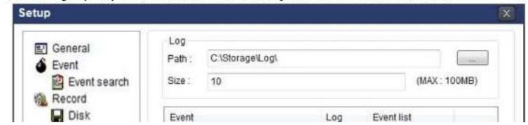
text_image
Setup General Event Event search Record Disk Log Path: C:\Storage\Log\ Size: 10 (MAX: 100MB) Event Log Event listEvent Search: Event log can be searched from the selected time.

text_image
Setup General Event Event search Record Disk Display Language About From: First 2011-04-26 12:00:00 AM To: Last 2011-04-26 7:48:54 PM Path: C:\Storage\Log\ Type Site Address Event Date/Time Save OK Cancel7-6-3. Record
Record Setup: You can set the recording conditions as the following; Always, Event, or Auto record. And you can also select target NSL and channel/channels. When you set the recording condition to event, you can set event for motion or alarm with duration.

text_image
Setup General Record ConditionRecord Local Storage Setup: You can select the local disk to record and the amount of disk space you want to allow the program to use for recording. You can also select the option to overwrite data or stop recording when the maximum amount of disk space is full.
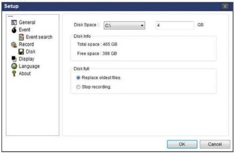
text_image
Setup General Event Event search Record Disk Display Language About Disk Space : C:\ 4 GB Disk Info Total space : 465 GB Free space : 398 GB Disk full Replace oldest files. Stop recording. OK Cancel7-6-4. Display
You can select the OSD (On Screen Display) to be displayed.

text_image
Setup General OSD7-6-5. Language
English, French and Spanish is selectable.
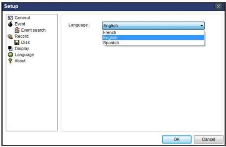
text_image
Setup General Event Event search Record Disk Display Language About Language: English French English Spanish OK Cancel7-6-6. About
"About" provides network client version information.
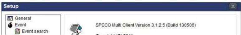
text_image
Setup General Event Event search SPECO Multi Client Version 3.1.2.5 (Build 130506)7-7. Remote Setup
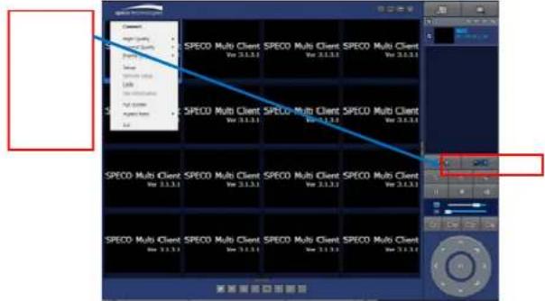
The menu settings for the NSL unit can be set over network.
Put the cursor of the mouse on the channel, which is connected to the site and right click on the mouse to open the submenu. Then the following window is displayed as below. Select the REMOTE SETUP.
text_image
Current High Quality SPECO Multi Client SPECO Multi Client SPECO Multi Client SPECO Multi Client SPECO Multi Client SPECO Multi Client SPECO Multi Client SPECO Multi Client SPECO Multi Client SPECO Multi Client SPECO Multi Client SPECO Multi Client SPECO Multi Client SPECO Multi Client SPECO Multi Client SPECO Multi Client SPECO Multi Client SPECO Multi Client SPECO Multi Client SPECO Multi Client SPECO Multi Client SPECO Multi Client SPECO Multi Client SPECO Multi Client SPECO Multi Client SPECO Single Client SPECO Single Client SPECO Single Client SPECO Multi Client SPECO Single Client SPECO Single Client SPECO Single Client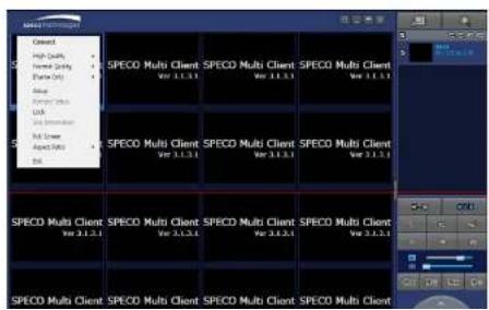
text_image
SPECO Multi Client SPECO Multi Client SPECO Multi Client Select High Quality Current Quality Failure Only Help Help/Help Help/Help Multi Client Apoq Data SPECO Multi Client SPECO Multi Client SPECO Multi Client Select Select Select Select Select Select Select Select Select Select Select Select Select Select Select Select Select Select Select Select Select Select Select Select Select Select Select Select Select Select Select Select Select Select Select Select Select Select Select Select Select Select Select Select Select Select Select Select Select Select SPECO Multi Client SPECO Multi Client SPECO Multi Client Select 3.1.2.1 Select 3.1.2.1 Select 3.1.2.1 Select 3.1.2.1 Select 3.1.2.1 Select 3.1.2.1 Select 3.1.2.1 Select 3.1.2.1 Select 3.1.2.1 Select 3.1.2.1 Select 3.1.2.1 Select 3.1.2.1 SelectsDisconnect
High Quality
Normal Quality
IFrame Only
Setup
Remote Setup
IP Camera Setup
Lock
Site Information
Full Screen

NOTICE
Web Setup is prohibited when NS is in local Setup Menu.
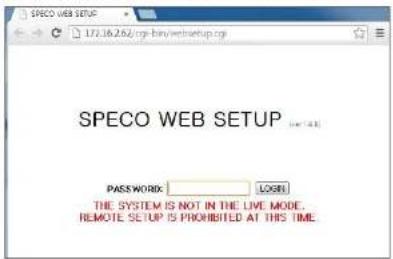
text_image
SPECO WEB SETUP PASSWORD: LOGI THE SYSTEM IS NOT IN THE LIVE MODE. REMOTE SETUP IS PROHIBITED AT THIS TIME7-7-1. IP Camera
Select IP Camera to set system and time settings

text_image
SPECO WEB SETUP IP CAMERA SYSTEM RECORD DEVICE DISPLAY NETWORK USER MANAGEMENT STORAGE UPGRADE INFORMATION CHANNEL CH8 PROTOCOL ONSP IP 0 0 0 0 PORT 554 WEB PORT 80 ID admin PASSWORD 17347-7-2. System
Select System to set system and time settings.
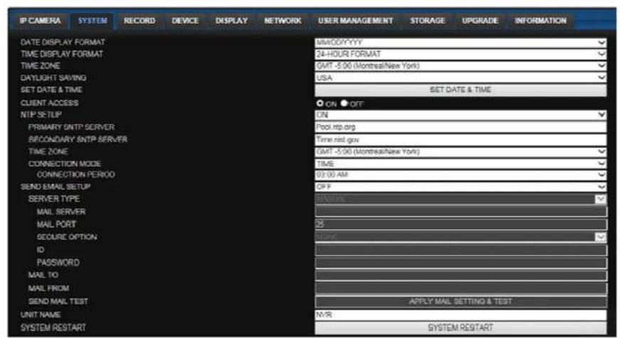
text_image
IP CAMERA SYSTEM RECORD DEVICE DISPLAY NETWORK USER MANAGEMENT STORAGE UPGRADE INFORMATION DATE DISPLAY FORMAT MMOD/YYYY TIME DISPLAY FORMAT 24-HOUR FORMAT TIME ZONE GMT -5.00 (Montreal/New York) DAYLIGHT SAVING USA SET DATE & TIME SET DATE & TIME CLIENT ACCESS ON OFF NTP SETUP ON PRIMARY SMTP SERVER Pool.rtp.org SECONDARY SMTP SERVER Time nrd.gov TIME ZONE GMT -5.00 (Montreal/New York) CONNECTION MODE TIME CONNECTION PERIOD 9:00 AM SEND EMAIL SETUP OFF SERVER TYPE MINUTE MAIL SERVER Mail PORT CS SECURE OPTION NONE ID PASSWORD MAIL TO MAIL FROM SND MAIL TEST APPLY MAIL SETTING & TEST UNIT NAME N/R SYSTEM RESTART SYSTEM RESTART• DATE DISPLAY FORMAT: Select the date display format.
• TIME DISPLAY FORMAT: Select the time display format.
• TIME ZONE: Select the TIME ZONE.
• DAYLIGHT SAVING: Select the area for DAYLING SAVING TIME
- SET DATE & TIME
In case setting the date & time, the changed date & tiem will be applied to the system.
And, the system will reboot.
When the user make the time back to the past, it does not show "TIME MISMATCH" message unlike the local system. The data on the duplicated period time will be deleted without WARNING.
- CLIENT ACCESS: Enable/Disable remote access through network client software.
- SEND MAIL TEST : E-mail settings sent a test mail to the registered account
• UNIT NAME: Name the HS
• SYSTEM RESTART : Restart the system
• SYSTEM EVENT NOTIFICATION

text_image
SYSTEM EVENT NOTIFICATION DISK EVENT SETUP HEALTH CHECK PERIOD DAILY HDD TEMPERATURE 50°C 140°F HDD BAD SECTORS 10% HDD ALMOST FULL 40% VIDEO CLIP SETUP PRE RECORD 2 SECOND(S) POST RECORD 1 SECOND(S) EVENTS AND NOTIFICATION ALARM-OUT BEEP E-MAIL HEALTH CHECK - - YES RESTART - - YES SHUTDOWN - - YES PANIC RECORD - - YES ALARM-IN NO - NO MOTION DETECTION NO - NO NO CONNECTION NO NO NO HDD TEMPERATURE 1 YES NO HDD BAD SECTORS - - YES HDD ALMOST FULL - - YES HDD FULL - - YES HDD FAILURE NO NO YESRELOAD APPLY
Allows the user to set EVENT NOFICIATION ON or OFF
HEALTH CHECK
(Allows the user to set MAIL STATUS periodically): DAILY or WEELY or MONTHLY
- HDD TEMPERATURE
- HDD BAD SECTOR
fails.
7-7-3. Record
Select RECORD tab to set the recording conditions.
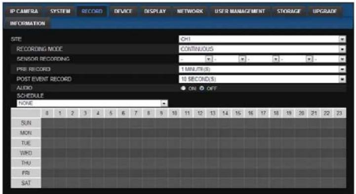
text_image
IP CAMERA SYSTEM RECORD DEVICE DISPLAY NETWORK USER MANAGEMENT STORAGE UPGRADE INFORMATION SITE CH1 RECORDING MODE CONTINUOUS SENSOR RECORDING - - - - - PRE RECORD 1 MINUTE(S) POST EVENT RECORD 10 SECOND(S) AUDIO ● ON ○ OFF SCHEDULE NONE 0 1 2 3 4 5 6 7 8 9 10 11 12 13 14 15 16 17 18 19 20 21 22 23 SUN MON TUE WFD THU FRI SATThese settings apply to the specified channel only.
- Recording Setup
o RECORDING MODE: CONTINUOUS, SCHEDULE, MOTION
o PRE RECORD: Sets whether to perform or not pre-recording.
o POST EVENT RECORD: Sets the duration of the event recording.
o AUDIO: Sets whether to perform or not audio recording.
o SCHEDULE: Sets the schedule recording.
7-7-4. Device
- DIGITAL DETERRENT: The schedule of digital deterrent can be set and a sound file can be uploaded to the NSL.
To set up schedule, select CHANNEL > select SOUND TYPE > select Area.
o CHANNEL: Select the Channel to configure audio input
o SOUND TYPE: Select the sound type.
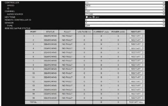
text_image
CON ROLLER SPEED ID CHANNEL AUDIO SOURCE KEY TONE REMOTE CONTROLLER ID SENSOR TYPE IEEE 802.34PNE STATUS PORT STATUS FAULT VOLTAGE (V) CURRENT (mA) POWER (kW) RESTART 1 SEARCHING NO FAULT 0 0 0 RESTART 2 SEARCHING NO FAULT 0 0 0 RESTART 3 SEARCHING NO FAULT 0 0 0 RESTART 4 SEARCHING NO FAULT 0 0 0 RESTART 5 SEARCHING NO FAULT 0 0 0 RESTART 6 SEARCHING NO FAULT 0 0 0 RESTART 7 SEARCHING NO FAULT 0 0 0 RESTART 8 SEARCHING NO FAULT 0 0 0 RESTART 9 SEARCHING NO FAULT 0 0 0 RESTART 10 SEARCHING NO FAULT 0 0 0 RESTART 11 SEARCHING NO FAULT 0 0 0 RESTART 12 SEARCHING NJ FAULT 0 0 0 RESTART 13 SEARCHING NJ FAULT 0 0 0 RESTART 14 SEARCHING NJ FAULT 0 0 0 RESTART 15 SEARCHING NJ FAULT 0 0 0 RESTART 16 SEARCHING NJ FAULT 0 0 0 RESTART TOTAL 0 0 0 RESTART ALLRELOAD APPLY
• CONTROLLER: Set the controller speed, type and ID.
• KEYTONE: Sets On or Off of Key Tone.
• REMOTE CONTROLLER ID: Sets an ID number of which remote control to receive commands.
• SENSOR: Select the type of sensor.
- IEEE 802.3af PSE Status: Table showing the status of all PoF devices connected to the NSP.
- OSD CONTRAST: Adjust the character contrast on the screen.
- MAIN MONITOR SEQUENCE: Setting for automatically switching the displayed video.
- SEQUENCE DWELL TIME: Sets the interval for automatically switching the screens.
- SITE: Name, Covert (These settings apply to the specified channel only).
7-7-6. Network
SPECO WEB SETUP

text_image
IP CAMERA SYSTEM RECORD DEVICE DISPLAY NETWORK USER MANAGEMENT STORAGE UPGRADE INFORMATION NETWORK TYPE P SUBNET MASK BATTERY DNS PRIMARY DNS SECONDARY DONS LOADLE DONS HOST NAME FORMAT/POUNT ADDRESS NETWORK POINT NETWORK AUDIO POINT WED POINT 172.16.241 258.215.010 172.96.1264 081.1-0.631 081.1-0.632 ON 6x4x 341000 ON OFF 245 248 248 WIN• NETWORK TYPE (Cannot be altered remotely)
o STATIC: The address setting mode is manual. Input IP, Gateway, Subnet Mask, and DNS IP.
- DHCP: The address setting mode is automatic.
• DDNS: Set whether to use DDNS service or not
○ HOST NAME: Allows the user to setup a domain name manually
o SUMBIT/UPDATE: Select ON to submit the settings
- ezDDNS: Enable ezDDNS to register the host name automatically
• NETWORK PORT: When connecting multiple NSs to the network, set a unique port number.
• NETWORK AUDIO PORT: Display the network audio port (NETWORK PORT + 1).
• WEB PORT: Set a web server port number.
implemented for each function accessed.
- USER NAME SETUP: Select which Username to change
- NEW USER NAME: Input the new username
- PASSWORD SETUP: Select Username to change Password
- CHANGE: Select whether to KEEP or CHANGE the current password.
- NEW PASSWORD: Input NEW Password if CHANGE was selected.
o CONFIRM PASSWORD: Input NEW Password again to confirm.
- PLAYBACK AUTHORITY: User can select which users have access to which channels.
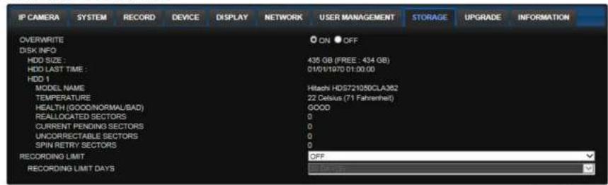
7-7-8. Storage
Select Storage to configure recording settings such as overwriting the hard disk and the setting a storage period for the recording data.
text_image
IP CAMERA SYSTEM RECORD DEVICE DISPLAY NETWORK USER MANAGEMENT STORAGE UPGRADE INFORMATION OVERWRITE ON OFF DISK INFO HDD SIZE : 435 GB (FREE : 434 GB) HDD LAST TIME : 01/01/1970 01:00:00 HDD 1 MODEL NAME Hitachi HD5721050CLA382 TEMPERATURE 22 Celsius (71 Fahrenheit) HEALTH (GOOD/NORMAL/BAD) GOOD REALLOCATED SECTORS 0 CURRENT PENDING SECTORS 0 UNCORRECTABLE SECTORS 0 SPIN RETRY SECTORS 0 RECORDING LIMIT OFF RECORDING LIMIT DAYSRELOAD APPLY
• OVERWRITE: Select on to continue recording by overwriting when the hard disk becomes full.
- RECORD LIMIT: Sets whether to limit or not the recording data storage period.
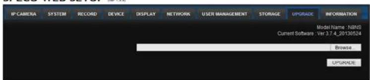
7-7-9. Remote Upgrade
SPECO WEB SETUP (var 1.0.8)
text_image
IP CAMERA SYSTEM RECORD DEVICE DISPLAY NETWORK USER MANAGEMENT STORAGE UPGRADE INFORMATION Model Name: N8NS Current Software: Ver 3.7.4_20130524 Browse UPGRADEShows the current Firmware version installed on NSL.
- Browse: Select BROWSE to locate the firmware file.
7-8. Operation
7-8-1. Addition, Delete, and Modify of NSL Sites
7-8-1-1. Addition of Sites
- Click SITE ADDITION button. And then the following window will be displayed as below.

text_image
Site Addition Site Info Site name: Site address: Potnumber: 5445 ID: Password: OK CancelSite Name: Input a name that properly describes a site.
IP Address: Input IP address (Public IP address of a router that NS is connected.) or Domain name
- Port Number: Default Port Number is "5445".
- ID: Input ID of NS. Default ID is "admin".
- Password: Input network password of NS. Default Password is "1111".
- Click OK button. And then the registered site is added on the directory window.

7-8-1-2. Deleting a Site
- Select the site/sites to delete from the directory window.

text_image
Net Finder Name Address NaaS 172.16.2.62 Address Port No. Mac Model Add Modify Delete Find IP Change Close- Click MODIFY button. And then the modified information is displayed as below.
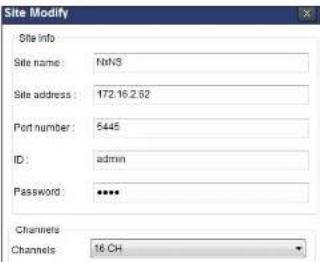
text_image
Site Modify Site info Site name: NetNS Site address: 172.16.2.62 Port number: 5445 ID: admin Password: **** Channels Channels: 16.CH
text_image
Screenshot of a video editing software interface showing a street scene with multiple camera and display panels, including Chinese text labels.7-8-2-2. Disconnect
- Select site/sites to disconnect from the directory window.

- Click DISCONNECT button, and then selected site/sites disconnected.
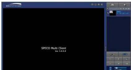
text_image
SPECD Multi Client View 3.0.4.4- Click CAPTURE button. And then a Capture window will be displayed as below.
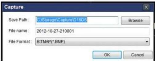
text_image
Capture Save Path: C:\Storage\Capture\D16DS File name: 2012-10-27-210801 File Format: BITMAP(*.BMP) Browse OK Cancel- Set Save Path, File Name, and File Format. And then click OK button.
- Still image is saved as set in Capture window.
7-8-4. Recording Video on Local PC During Live
- Click SETUP button. And then a setup window will be displayed as below.
- Select Record and set the values.
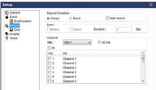
text_image
Setup General Event Event search Record Disk Display About Record Condition Always Event Auto record Event Motion Alarm Duration: 5 Sec Channel Site: Site 1 All site All NO. CH 1 Channel 1 2 Channel 2 3 Channel 3 4 Channel 4 5 Channel 5 6 Channel 6-
Click RECORD ON button. And the color of button is changed.
-
Live video data is recorded as set in Record and Disk setup. These video data can be searched and play-backed with Local Playback.

text_image
HC01 File Edit View Favorites Tools Help Back Search Folders Address C:\MyUsage\HC01 Name Size Type Data Modified 2000068 Filu Follow 6/8/2009 4:00 PM 20000610 Filu Follow 6/10/2009 3:15 PM 20000317_cdf 6,276 KB NOL File 3/17/2009 5:24 PM 20000317_3.mdb 102,102 KB NOL File 3/17/2009 5:35 PM 20000317_3.mdb 102,102 KB NOL File 3/17/2009 5:44 PM 20000317_3.mdb 102,102 KB NOL File 3/17/2009 5:52 PM 20000317_3.mdb 73,645 KB NOL File 3/17/2009 5:23 PM7-8-5. Local Playback and Remote Playback
7-8-5-1. Playback of Recorded Video on a Local PC
- Click LOCAL PLAYBACK. And then Playback Window will be displayed over the Live Window.
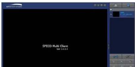
text_image
SPECO Multi Client VSP 3.0.6.4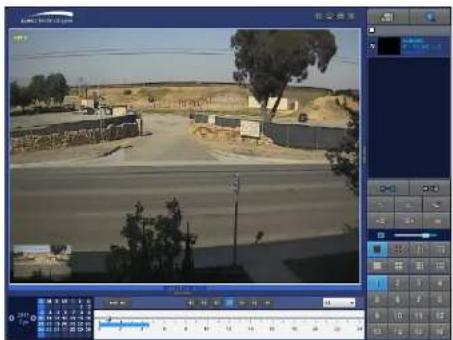
text_image
Video editing software interface displaying a highway scene with multiple lanes and a timeline ruler on the right.- Use the mouse scroll to digitally zoom in and out from a single channel display.
7-8-5-2. Playback of Recorded Video on Remote NSL
- Click REMOTE PLAYBACK. And then Playback Window will be displayed over the Live
Window.

text_image
SPECO Multi Client Ver 1.8.3.6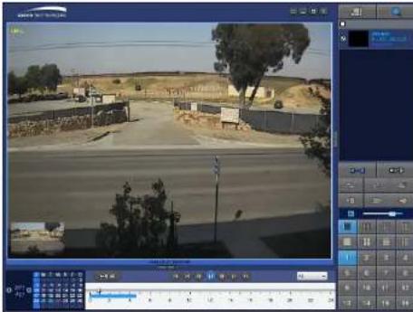
text_image
Screenshot of a video editing software interface showing a highway scene with multiple buildings and a timeline ruler on the right.7-8-6. AVI Backup during Playback
You can back up the recorded videos in AVI format during playback.
- Double-click the target channel to backup.
- Select the beginning time by using the search calendar and timeline scale bar.

text_image
2011 Apr S M T W T F S: 1 2 3 4 5 6 7 8 9 10 11 12 13 14 15 16 17 18 19 20 21 22 23 24 25 26 27 28 29 30 0 2 4 6 8 10 12 14 16 18 20 22 24- Click EZCOPY START button on the timeline scale to select the beginning point of the backup.
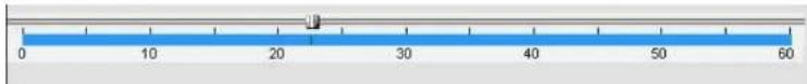
text_image
0 10 20 30 40 50 60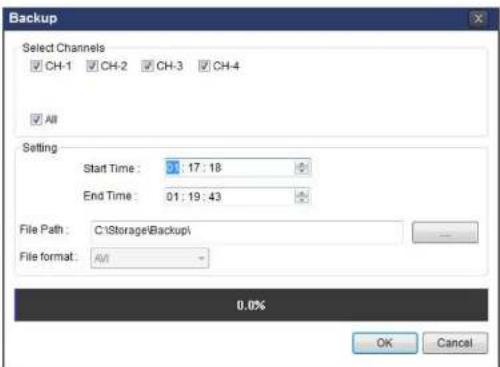
text_image
Backup Select Channels CH-1 CH-2 CH-3 CH-4 All Setting Start Time: 01:17:18 End Time: 01:19:43 File Path: C:\Storage\Backup\ File format: A/A 0.0% OK Cancel- You can also set the beginning time and ending time on this window. After selecting a channel for backup, click the OK button. The backup will begin.
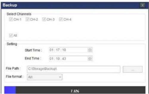
text_image
Backup Select Channels CH-1 CH-2 CH-3 CH-4 All Setting Start Time: 01:17:18 End Time: 01:19:43 File Path: C:\Storage\Backup\ File format: AM 7.6%8. Network Access Using the Web-Browser Viewer
The NS provides a live remote monitoring feature by web-browser viewer. (NOTE: Web-Browser is only available for Internet Explorer)
- Check the IP address of the NS from SETUP>SYSTEM>DESCRIPTION>IP ADDRESS or
- Input the IP address or Domain name address that you pre-registered.

text_image
Address http://172.16.1.52 Go- Click this bar. Then the dialog box is displayed.

- Click "Install" to download and install the ActiveX control.
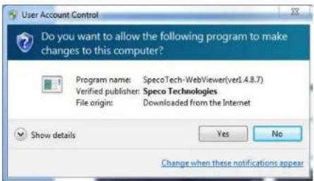
text_image
User Account Control Do you want to allow the following program to make changes to this computer? Program name: SpecoTech-WebViewer(verl.4.8.7) Verified publisher: Speco Technologies File origin: Downloaded from the Internet Show details Yes No Change when these notifications appear- The Web Browser Viewer will be displayed as below after the ActiveX installation
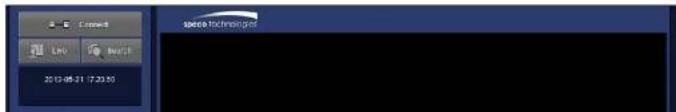
text_image
space technology LNO BUTS 2013-05-21 7:23:50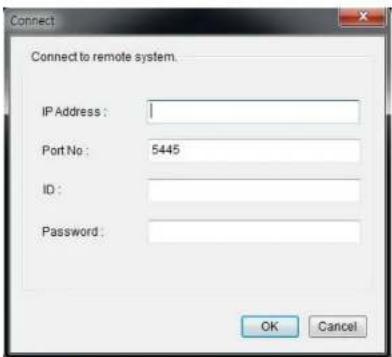
text_image
Connect Connect to remote system. IP Address : 1 Port No : 5445 ID : Password : OK Cancel- Site Name: Input a name that properly describes a site.
- IP Address: Input IP address (Public IP address of a router that NS is connected.) or Domain name
- Port Number: Default Port Number is "5445".
• ID: Input ID of NS. Default ID Is "admin". -
Password: Input network password of NS. Default Password is "1111".
-
Then the cameras connected to the NS are displayed on the screen.
- Use mouse scroll to digitally zoom in and out from a single channel display.

text_image
speed technology On 1 On 2 1 2 3 4 2013-05-21 18:23:13 172.15.2529. Network Access Using the Smart Phone Viewer

Notice
Data Usage applied without Wi-Fi connection. Please check with your Phone Carrier.
9-1. App Viewer for iPhone
- Enter the Apple App Store.


- Search "Speco Player" in the App Store.

Notice
SPECO Player is for the NS, NSL, HS, HT, VT, WVT and HD series. SPECO Player is not compatible with the T Series (TH, TN or TL) or the PC Series.
9-1-1. Live
- Open the installed "Speco Player" App and click action to add a remote device.
- Enter the site name, IP or DDNS address, Network Port number (default 5445), ID(default admin) and Password (default 1111). Then, click "Save" button.
| About | Device List | + |
| Demo DS | > | |
| Demo HS | > | |
| Demo NSP | > |

- The app will display the selected channel(s). Double tap the channel screen to switch 1 channel display to 4, 8, 10, 16 channels split display depending on the DVR.

text_image
Back LIVE 06-09-16 17:57:07 CH 01 T-Mobile 4G 2:04 PM 42% CH 03 T-Mobile 4G 2:04 PM 42% CH 04 T-Mobile 4G 2:04 PM 42% CH 05 T-Mobile 4G 2:04 PM 42% CH 06 T-Mobile 4G 2:04 PM 42% CH 07 T-Mobile 4G 2:04 PM 42% CH 08 T-Mobile 4G 2:04 PM 42% CH 09 T-Mobile 4G 2:04 PM 42% CH 10 T-Mobile 4G 2:04 PM 42% CH 11 T-Mobile 4G 2:04 PM 42% CH 12 T-Mobile 4G 2:04 PM 42% CH 13 T-Mobile 4G 2:04 PM 42% CH 14 T-Mobile 4G 2:04 PM 42% CH 15 T-Mobile 4G 2:04 PM 42% CH 16 T-Mobile 4G 2:04 PM 42% CH 17 T-Mobile 4G 2:04 PM 42% CH 18 T-Mobile 4G 2:04 PM 42% CH 19 T-Mobile 4G 2:04 PM 42% CH 20 T-Mobile 4G 2:04 PM 42% CH 21 T-Mobile 4G 2:04 PM 42% CH 22 T-Mobile 4G 2:04 PM 42% CH 23 T-Mobile 4G 2:04 PM 42% CH 24 T-Mobile 4G 2:04 PM 42% CH 25 T-Mobile 4G 2:04 PM 42% CH 26 T-Mobile 4G 2:04 PM 42% CH 27 T-Mobile 4G 2:04 PM 42% CH 28 T-Mobile 4G 2:04 PM 42% CH 29 T-Mobile 4G 2:04 PM 42% CH 30 T-Mobile 4G 2:04 PM- To select the display mode(1, 4, 9, 10 or 16 split display), tap the arrow menus button
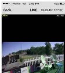
text_image
1-Mobile 02 2:05 PM 4:26 Back LIVE 06-09-16 17:57:37 21:01 +89-1-2. PTZ Control
To control the PTZ functions of the camera, tap the menu button. Then PTZ menu icons will display. Using the PTZ icon on the screen, can control PTZF functions.
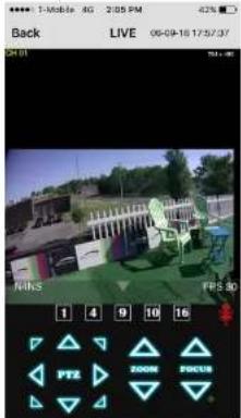
text_image
1: Mobile 4G 2:05 PM Back LIVE 06-09-16 17:57:37 NOKS FRS 3D 1 4 9 10 16 PT2 ZOOM ZOCUS9-1-3. Playback
- Select mode as 'Playback' 📄 and click 'Connect' button. Then select Date & Time and click 'Connect' button.
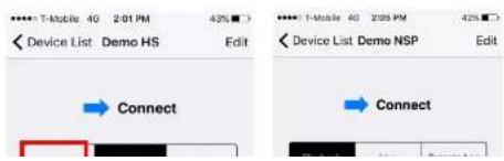
text_image
Device List Demo HS Edit Connect Device List Demo NSP Edit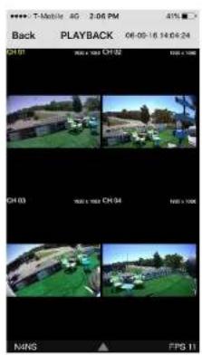
text_image
Back PLAYBACK 06-09-18 14:04:24 01:01 01:02 01:03 01:04 01:05 01:06 01:07 01:08 01:09 01:10 01:11 MINS FPS 11→
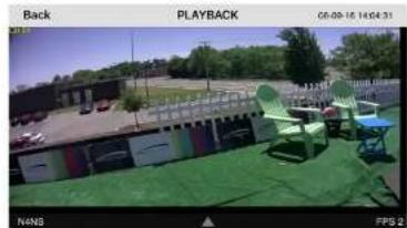
natural_image
Outdoor scene with green outdoor chairs and a building, no visible text or symbols- Tap the menu button. Then Playback menu icons will display.
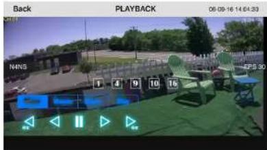
text_image
Back PLAYBACK 06-09-16 14:04:30 NNS 1 4 9 10 15 EPS 309-2. App Viewer for Android Phone
- Enter the Android Market.

text_image
speco player Main menu Live View / Playbox ScreenShot User Speco Player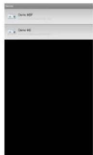
text_image
Delete MDP Delete MRL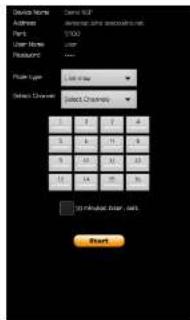
text_image
Select channels Address: 0.00000000000000000000000000000000000000000000000000000000000000000000000000000000000000 Address: 123456789 Part Number: 123456789 User Name: user Features: Name Type: set-up Select Channels: 123456789 2 3 4 5 6 7 8 9 10 11 12 13 14 15 16 17 18 19 20 21 22 23 24 25 26 27 28 29 30 31 32 33 34 35 36 37 38 39 40 41 42 43 44 45 46 47 48 49 50 51 52 53 54 55 56 57 58 59 60 61 62 63 64 65 66 67 68 69 70 71 72 73 74 75 76 77 78 79 80 81 82 83 84 85 86 87 88 89 90 91 92 93 94 95 96 97 98 99 100- The app will display the selected channel(s). Double tap the channel screen to switch 1 channel display to 4 channels split display.
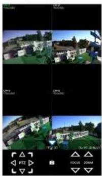
natural_image
Four-panel image showing a residential building with surrounding greenery and a blue sky, alongside a small UI panel with icons for camera, overlay, and status bar (no readable text or symbols in the main visual content)- The app will display the selected channel(s). Double tap the channel screen to switch 1 channel display to 4 channels split display.

natural_image
Four-panel image sequence showing outdoor scenes with buildings and greenery, no visible text or symbols9-2-3. PTZ Control
To control the PTZ function of the camera, tap the channel screen, and then the channel name will be highlighted in Light Green. Using the PTZ menu icons on the screen, control PTZF.

natural_image
Two-panel image showing a 3D-rendered building with trees and a person in the background (no visible text or symbols)APPENDIX: Network Connection - LAN
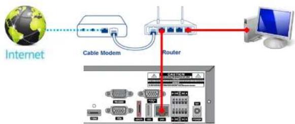
flowchart
graph TD
    A["Internet"] --> B["Cable Modem"]
    B --> C["Router"]
    C --> D["PC"]
    C --> E["Computer"]
- Install the network client software from the supplied CD.
- Check the IP address from SETUP > SYSTEM > DESCRIPTION or SETUP > NETWORK of NS.
| Model Name | N4NSL |
| Software Version | Ver 5.2.1_20160819 |
| Storage Size | 1862 GB |
| Network Type | Dhcp |
| IP Address | 172.16.2.7 |
| MAC Address | 00:02:69:0A:1F:0C |
| DDNS Status | DDNS Off |
| Unit Name | NVR |
| Remote Controller ID | 0 |
- Run the network client software.

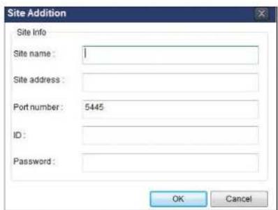
text_image
Site Addition Site Info Site name: Site address: Port number: 5445 ID: Password: OK Cancel- Input Site Name, Site Address (IP address), Port Number, and Password on the connect window.
• Site Name: Input a name that properly describes a site.
• IP Address: Input IP address
• Port Number: Default Port Number is "5445".
• ID: Input ID of NS. Default ID is "admin".
- Password: Input network password of NS. Default Password is "1111".
- Select a site by checking the box, and Press button to connect to the site.

text_image
space technologies CH-2 NO VIDEOAPPENDIX: Network Connection – Internet and DDNS
Dynamic Domain Name System (DDNS) allows a domain name to be constantly synchronized with a dynamic IP address. A current dynamic IP address is being associated with a static domain name.
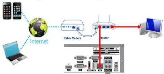
flowchart
graph TD
    A["Internet"] --> B["Cable Modem"]
    B --> C["Router"]
    C --> D["Computer"]
    A --> E["Laptop"]
    B --> F["Mobile Phone"]
    C --> G["Server with Ethernet"]
    style A fill:#f9f,stroke:#333
    style B fill:#ccf,stroke:#333
    style C fill:#cfc,stroke:#333
    style D fill:#fcc,stroke:#333
    style E fill:#ffc,stroke:#333
    style F fill:#fcc,stroke:#333
    style G fill:#ffc,stroke:#333
- Go to SETUP>NETWORK>DDNS and set the DDNS SERVER to ON.

text_image
Enable DDNS Host Name Kosovo Submit/Update ezDDNS on off off Apply CloseIf you set ezDDNS to ON, the host name is automatically generated and registered.
-
Go to SETUP>NETWORK>DDNS>HOST NAME. Manually enter a domain name using the virtual keyboard and click ENTER button.
-
When DDNS setting is done, click the APPLY button. Otherwise DDNS setting will not be applied.
- When you exit SETUP menu, DDNS NOTIFY window will pop up.
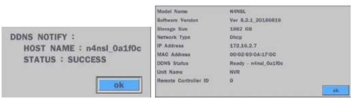
text_image
DDNS NOTIFY : HOST NAME : n4nsl_0a1f0c STATUS : SUCCESS ok Model Name N4NSL Software Version Ver 8.2.1_20160819 Storage Size 1882 GB Network Type Dhcp IP Address 172.16.2.7 MAC Address 00:02:09:0A:1F0C DDNS Status Ready - n4nsl_0a1f0c Unit Name NVR Remote Controller ID 0 ok- DDNS registration status can be checked from SYSTEM INFORMATION or SETUP>SYSTEM>DESCRIPTION>DDNS STATUS
- Check the NETWORK PORT (Default: 5445), WEB PORT (Default: 80), and the IP Address of the NS from SETUP>NETWORK.

text_image
Network Network Type IP 172.16.2.3 Subnet Mask 255.255.0.0 Gateway 172.16.1.254 DNS (Primary) 168.126.63.1 DNS (Secondary) 168.126.63.2 DDNS select Network Video Port 5445 Network Audio Port 5446 Web Port 80 443
text_image
SPECO Multi Client Ver 3.1.2.5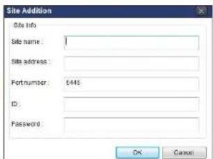
text_image
Site Addition Site Info Site name: Site address: Portnumber: 6445 ID: Password: OK Cancel-
Input Site Name, Site Address (IP address), Port No., and Password on the connect window.
-
Site Name: Input a name that properly describes a site.
• IP Address: Domain name or Public IP address of a router that NS is connected.
• Port Number: Default Port Number is "5445".
• ID: Input ID of NS. Default ID is "admin". -
Password: Input network password of NS. Default Password is "1111".
-
And select the OK button. Then, press button after checking the left check box.
