VL5700BPVFW - Security Camera Speco Technologies - Free user manual and instructions
Find the device manual for free VL5700BPVFW Speco Technologies in PDF.

User questions about VL5700BPVFW Speco Technologies
0 question about this device. Answer the ones you know or ask your own.
Ask a new question about this device
Download the instructions for your Security Camera in PDF format for free! Find your manual VL5700BPVFW - Speco Technologies and take your electronic device back in hand. On this page are published all the documents necessary for the use of your device. VL5700BPVFW by Speco Technologies.
USER MANUAL VL5700BPVFW Speco Technologies
natural_image
Close-up of a camera with white LED module mounted on a flanged base (no visible text or symbols)
text_image
CAUTION RISK OF ELECTRIC SHOCK DO NOT OPEN! CAUTION TO REDUCE THE RISK OF ELECTRIC SHOCK DO NOT REMOVE COVER/OR BACK. NO USER-SERVICEABLE PARTS INSIDE. REFER SERVICING TO QUALIFIED SERVICE PERSONNEL. ISO14001 CE FC
The lightning flash with an arrowhead symbol, within an equilateral triangle is intended to alert the user to the presence of uninsulated dangerous voltage within the product's enclosure that may be of sufficient magnitude to constitute a risk of electric shock to persons.

The exclamation point within an equilateral triangle is intended to alert the user to the presence of important operating and maintenance (servicing) instructions in the literature accompanying the appliance.
INFORMATION - This equipment has been tested and found to comply with limits for a Class A digital device, pursuant to part 15 of the FCC Rules & CE Rules. These limits are designed to provide reasonable protection against harmful interference when the equipment is operated in a commercial environment. This equipment generates, uses, and can radiate radio frequency energy and, if not installed and used in accordance with the instruction manual, may cause harmful interference to radio communications. Operation of this equipment in a residential area is likely to cause harmful interference in which case the user will be required to correct the interference at
Contents
Contents 3
Precautions 4
Safety Instructions 5
Menu Set Up
▶ OSD Control Button 7
▶ Set Up Menu 8
▶ Menu Set Up 11
▶ Lens 12
▶ Exposure 13
▶ Back Light 15
▶ White Bal. 18
▶ Day & Night 19
▶3DNR 21
▶ Special 22
◆ Camera Title 22
◆ D - Effect 25
◆ Motion 27
▲ Deliver 20
Precautions
Do not install the camera in extreme temperature conditions.

natural_image
Cartoon illustration of two anthropomorphic surveillance cameras emitting flames, with a cloud above (no text or symbols)Only use the camera under conditions where temperatures are between
-10°C and +50°C. Be especially careful to provide ventilation when operating under high temperatures.
Do not install the camera under unstable lighting conditions.

Severe lighting change or flicker can cause the camera to work improperly.
Do not touch the front lens of the camera.

This is one of the most important parts of the camera. Be careful not to leave fingerprints on the lens cover.
Never keep the camera pointed directly at strong light.

natural_image
Illustration of a sun shining on a surveillance camera and a helmet, both showing smiling faces (no text or symbols)It can cause malfunctions to occur.
Do not drop the camera or subject it to physical shocks.

natural_image
Illustration of two surveillance cameras with a person inside, falling off from the ground (no text or symbols)Severe lighting change or flicker can
Do not expose the camera to radiocavity.

If exposed to radioactivity the CCD
Sefety Instructions
Precautions for use
This camera should be installed by qualified personnel only
There are no user serviceable parts inside
Do not disassemble this camera other than to make initial adjustments
- Use a UL approved regulated 24 volt AC or 12 volt DC power supply
Use appropriate low voltage power cable to prevent fire or electrical shock
Please insure that your installation area can support the weight of the camera
Please handle this camera carefully :
Do not use a strong or abrasive detergent when cleaning the camera
Do not install near cooling or heating device
White LED Camera
DC Auto Iris Varifocal Lens(4mm-9mm) / IR LED Built-in 14pcs + White LED 2pcs
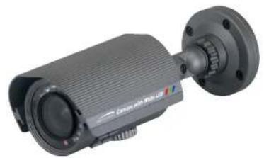
natural_image
Exterior view of a black surveillance camera with mounted lens and mounting flange (no visible text or symbols)
text_image
1/3" CCD BCL & MTR BLT BLT0 BLT0 2000000000 Auto-Wide Balance Air-Solar Balance 250 V BLC Compression High Speed Shuttle Maxim Minim 600 Maximum Recovery Air-Voltage Power Source IP65 低速电机VL5700BPVF
VL5700BPVFW
600TV Lines
DC Auto Iris Varifocal Lens
(4mm-9mm)
True Day/Night Capability
ICR-IR Cut Filter Removable
850nm IR LEDs * 14pcs
White LED * 2pcs

IR LED's 14EA & White LED's 2EA
& Heater 1EA
SPECIFICATIONS
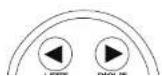
- Type A, Type B, Type C of OSD button could be used when it needs to OSD control.
- Type D is extra Option (wired Remote controller)
Type A
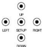
Type.B

Type C

Type D (Option)
How to Set Up the camera menu
- Setup Menu
| SET UP MENU | DEFAULTSULT SET | MENU | ||
| LENS | DC | BRIGHTNESS (0~100 Adjustable) | ||
| RETURN | RET | |||
| END | ||||
| MANUAL | ||||
| EXPOSURE | SHUTTER | AUTO, 1/60, 1/50, FLK, 1/250, 1/500, 1/1000, 1/2000, 1/5000, 1/10000, 1/100000, x256, x128, x64, x32, x16, x8, x4, x2 | ||
| AGC | OFF | |||
| LOW | ||||
| MIDDLE | ||||
| HIGH | ||||
| OFF | ||||
| SENSE-UP | AUTO | SENSE-UP(x2 - x256 Level Selectable) | ||
| RETURN | RET | |||
| END | ||||
| BLC | OFF | |||
| BLC | GAIN | LOW | ||
| MIDDLE | ||||
| HIGH | ||||
| AREA | POSITION | |||
| SIZE | ||||
| AGAIN | ||||
| DEFAULT | ||||
| RETURN | RET | |||
| END | ||||
| LISHC | LEVEL 0~8 Selectable | |||
| MODE | ALL DAY | |||
| NIGHT ONLY | ||||
| AREA | POSITION | |||
| SIZE | ||||
| DAY/NIGHT | COLOR | |||
| AUTO | DELAY (0 -63 Adjustable) | |||
| D->N(AGC) (18 - 208 Adjustable) | ||||
| N->D(AGC) (0 -160 Adjustable) | ||||
| RETURN | RET | |||
| END | ||||
| EXT | ||||
| S/W | BURST | O N/OFF | ||
| IR SMART | ON | GAIN | ||
| AREA | ||||
| RETURN (RET/END) | ||||
| OFF | ||||
| 3DNR | ON | LEVEL (RANGE 0 ~ 100 Level Selectable) | ||
| RETURN | RET | |||
| END | ||||
| OFF | ||||
| CAM TITLE | O N/OFF | |||
| D-EFFECT | FREEZE | O N/OFF | ||
| MIRROR | MIRROR | |||
| V-FLIF | ||||
| ROTATE | ||||
| OFF | ||||
| D-ZOOM ON | D-ZOOM (x1 ~ x32) | |||
| PAN (-100 ~ 100) | ||||
| TILT (-100 ~ 100) | ||||
| RETURN (RET/END) | ||||
| NEG. IMAGE ON/OFF | ||||
| RETURN | RET | |||
| END | ||||
| RS485(OPTION) | CAM ID | |||
| ID DISPLAY ON/OFF | ||||
| BAUROATE | ||||
| RETURN RET | ||||
| END | ||||
| ARCA SELECT (ARCA1 ~ ARCA4) | ||||
| DEFECT | SENSE-UP (x4 ~ x64) | |||
| DIFFERENCE (1 -6) | ||||
| START | ||||
| RETURN | RET | |||
| END | ||||
| RETURN | RET | |||
| END | ||||
| ADJUST | SHARPNESS | 0 ~31 Level Adjustable | ||
| MONITOR | CRT | LEVEL (0 -63) | ||
| BLUE GAIN (0 ~100) | ||||
| RED GAIN (0 -100) | ||||
| RETURN | RET | |||
| END | ||||
| LCD | GAMMA (USER ~ 1.00) | |||
| LEVEL (0 -63) | ||||
| BLUE GAIN (0 ~100) | ||||
| RED GAIN (0 -100) | ||||
| RETURN | RET | |||
| END | ||||
| USER | GAMMA (USER ~ 1.00) | |||
| LEVEL (0 -63) | ||||
| BLUE GAIN (0 ~100) | ||||
| RED GAIN (0 ~100) | ||||
| RETURN | RET | |||
| RETURN | RET | |||
| END | ||||
| RESET | FACTORY RESET | |||
| RETURN | RET | |||
| END | ||||
| EXIT | ||||
Menu Set Up
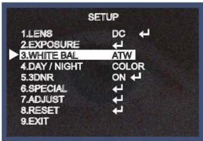
Menu items can be selected by using the OSD buttons of the camera
- Press the Set Up button.
* The Set Up menu will be displayed on the monitor.

text_image
SETUP 1.LENS DC 2.EXPOSURE 3.WHITE BAL ATW 4.DAY / NIGHT COLOR 5.3DNR ON 6.SPECIAL 7.ADJUST 8.RESET 9.EXIT- Move and select the required function using the Up and Down button.
* Move the arrow indicator Up or Down to select the desired feature by pressing the Up or Down button.

- Change menu settings using the Left or Right button.
* Available values or Status are displayed by pressing the Left or Right buttons. Press the button until desired value / status is displayed.
- After Changing the setting move the arrow indicator to EXIT and press the SET button to EXIT.
NOTE
* Move to the available submenu by moving ←arrow to desired feature.
* Submenu is not available when this symbol is display "----"
Lens
- Move the arrow indicator to LENS using the Up and Down buttons on the Set Up menu screen.
- Select the desired lens type by pressing the Left or Right button.

NOTE
* When DC is selected, the brightness can be adjusted. The brightness control range is 1 \~ 100.
Lens
BRIGHTNESS
100
RETURN
- Press the RETURN to return to the SETUP menu.
Exposure
This function is used to select Automatic or Manual shutter speed control.

text_image
EXPOSURE SHUTTER AUTO AGC MIDDLE SENS-UP AUTO ← BLC OFF ← D-WDR OFF ← RETURN RET ←NOTE
*Shutter: Select Shutter using the Up or Down button, you can adjust the shutter speed from 1/60, FLK, 1/250\~1/100,000. →FLK: Select FLK mode if flickering occurs; caused by the unmatched frequency of electric light. If select FLK mode, sense-up does not operate.
* AGC(AUTO GAIN CONTROL):
A higher gain increases brightness but also increases any noise.
OFF : Deactivates the AGC function
LOW : Sets automatic gain control to LOW.
MIDDLE : Sets automatic gain control to MIDDLE.
* RETURN:
Select Return to save the changes in the EXPOSURE menu and return to the SETUP menu.
NOTE
* Pressing the SET button in AUTO mode allows adjustment of image brightness by increasing or decreasing the shutter speed (x2 \~x256).
* The higher the level, the brighter the image becomes, but it is possible that an after image (ghosting) could appear.
* When SENS-UP is activated the increased magnification can induce noise and pixelation; this is quite normal.
Back Light(BLC)
This camera witch is using 3D-DNR DSP provides intelligent light level control to overcome even strong backlight conditions.
| BLC | |
| GAIN | MIDDLE |
| AREA | ← |
| DEFAULT | ← |
| RETURN | RET |

text_image
POSITIONPICTURE 1

text_image
SIZEPICTURE 2
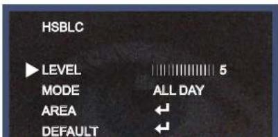
* HSBLE: HSBLC function is especially effective for reading car number plates at the night time.
You can select and define the required observation area for the target object and ignore a strong light area.
Press the "ENTER" button at the AREA menu, you can change the position as shown in Picture 1.
Press the "ENTER" button again after area setting, you can change the position as shown in Picture 2.
Default: Press the Default to return to factory defaults.
text_image
HSBLC LEVEL 5 MODE ALL DAY AREA ← DEFAULT ←
natural_image
Front view of a car with headlights on, showing grille and dashboard (no visible text or symbols)HSBLC OFF

natural_image
Front view of a Mercedes-Benz light commercial vehicle with illuminated grille and license plate (no visible text or symbols)HSBLC ON
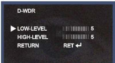
* D-WDR: This camera which is using 3D-DNR DSP provides intelligent light level control to overcome even strong backlight conditions.
→OFF: D-WDR function does not operate.
When there are simultaneous bright & dark image area WDR makes them both distinct and can be selected as OUTDOOR and INDOOR.
text_image
D-WDR ▶ LOW-LEVEL 5 HIGH-LEVEL 5 RETURN RET ←White Balance
The White Balance function is used to control the "on-screen" colors.
- Move the arrow indicator to WHITE BAL on the SETUP menu screen using the Up and Down button.
- Select the desired mode by using the Left or Right button.
text_image
SETUP 1.LENS DC 2.EXPOSURE ← 3.WHITE BAL ATW 4.DAY / NIGHT COLOR 5.3DNR ON 6.SPECIAL ← 7.ADJUST ← 8.RESET ← 9.EXIT* There are three user selectable White Balance settings available.
* ATW : (Auto Tracking White Balance)
Normal setting; when the color temperature range is from 1,800°K to 10,500°K. (Ex: a fluorescent lamp or outdoors)
* AWB : The White Balance is automatically adjusted in a specific environment.
* AWC → SET : To obtain the best results press the SET button while the camera is focused onto white
Day / Night
Picture can be displayed in either colour of black and white.
- Select DAY / NIGHT using the Up or Down button on the SETUP menu screen.

text_image
SETUP 1.LENS DC 2.EXPOSURE ← 3.WHITE BAL ATW 4.DAY / NIGHT AUTO 5.3DNR ON ← 6.SPECIAL ← 7.ADJUST ← 8.RESET ← 9.EXIT- Select the desired mode using the Left and Right buttons.
* COLOR : The picture is always displayed in color.
* BW : This picture is always displayed in black and white.
Select BW using the button and press the menu to activate COLOR BURST option.
IR SMART : It controls the IR LED(bright portion base), satuation is not expected.

text_image
IR SMART GAIN AREA RETURN 10 RET
text_image
SIZEAREA
natural_image
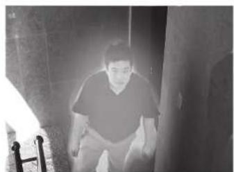
Black-and-white photo of a person sitting on a doorway, no visible text or symbols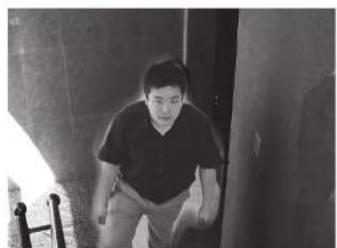
natural_image
Black-and-white photo of a person sitting in a hallway, viewed from above (no visible text or symbols)SMART IR ONSMART IR OFF
→ AUTO: The mode will automatically switches to COLOR in normal condition and switches to BW mode when ambient illumination is low
3DNR
3DNR is used to reduce the level of background noise in a low luminance environment.
- Move the arrow indicator to 3DNR by using the Up and Down button.

text_image
SETUP 1.LENS DC 2.EXPOSURE ← 3.WHITE BAL ATW 4.DAY / NIGHT AUTO 5.3DNR ON 6.SPECIAL ← 7.ADJUST ← 8.RESET ← 9.EXIT- Select whether or not to activate 3DNR by using the Left and Right buttons.
* ON: Activates 3DNR - Digital noise reduction can be adjusted between 0 \~ 100.
* OFF: Deactivates 3DNR - noise is not reduced.

text_image
3DNR LEVEL 50Special
When the SETUP menu screen is displayed, select SPECIAL using the Up and Down buttons.
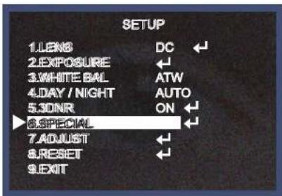
text_image
SETUP 1.LENS DC 2.EXPOSURE ← 3.WHITE BAL ATW 4.DAY / NIGHT AUTO 5.30NR ON 6.SPECIAL 7.AJUST 8.RESET 9.EXITSelect one of the mode using the Up and Down button.

text_image
SPECIAL 1. CAM TITLE OFF 2. D - EFFECT 3. MOTION OFF 4. PRIVACY OFFNOTE
* When CAMERA TITLE is set to OFF, the CAMERA TITLE is not displayed on the monitor.
1-3) Press the SETUP button.
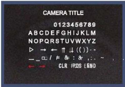
text_image
CAMERA TITLE 0123456789 ABCDEFGHIJKLMNOPQRSTUVWXYZ ► → ← ↑ ↓ ( ) - — □ / ≠ & : & ,: ~ , . ← → CLR FIOS EAND1-4) The CAMERA TITLE can be up to 15 alphanumeric characters in length.
① Move the cursor to choose an alphanumeric character.

NOTE
* In cases where the wrong Camera ID has been input.....
Move the cursor to CLR and press SETUP button to erase characters from left to right, and repeat the above steps to input the characters again.
1-5) To select the position where the Camera ID should be displayed on the screen.
① Move the cursor to POS and press the SET button.
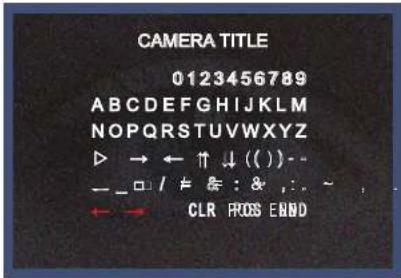
text_image
CAMERA TITLE 0123456789 ABCDEFGHIJKLMNOPQRSTUVWXYZ → ← ↑ ↓ ( ) - — □ / # & : & , : . ← → CLR FIOS END③ Select a new position by using the four directional button, Press the SET button to confirm the position.

natural_image
Interior view of a museum hallway with marble paintings on walls and informational display panels (no visible text or symbols)2. D - EFFECT
Move the cursor to D-EFFECT and press the SET button to set the other image functions.
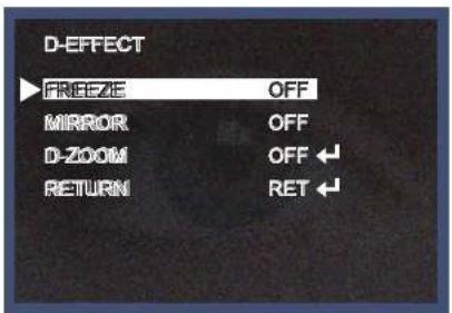
text_image
D-EFFECT FREEZE OFF MIRROR OFF D-ZOOM OFF RETURN RET* V-FLIP : Flip the image vertically on the screen.
* ROTATE : Flip the horizontal image vertically on the screen.
* OFF : Disabled.

natural_image
Street view of a multi-lane highway with cars and a tunnel entrance, surrounded by trees (no visible text or signage)
text_image
Street photo showing a highway with multiple cars and a tunnel entrance, featuring visible Chinese signage above the road.MIRROR ON MIRROR OFF
2-2) D - ZOOM: Digital zoom available, range x1 \~ x32.
PAN : The pan range can be controlled between -10 \~ + 100
TILT : The tilt range can be controlled between -10 \~ + 100

2-3) GAMMA : Desired gamma values can be adjusted between 0.05 \~ 1.00.
2-4) NEG. IMAGE :
ON : Activates negative image just like film
OFF : Normal image
2-5) RETURN : Move the arrow indicator to RETURN after complete the setup to return to SPECIAL menu.
- MOTION
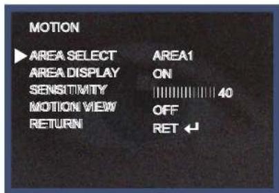
text_image
MOTION ▶ AREA SELECT AREA1 AREA DISPLAY ON SENSITIVITY 40 MOTION VIEW OFF RETURN RET ↙
text_image
POSITION SIZE
natural_image
Interior view of a modern hallway with ceiling lights and wooden flooring (no visible text or symbols)4. PRIVACY
Hide an area you want to hide on the screen.
4-1). When the SPECIAL menu screen is displayed, press the Up and Down buttons to set to PRIVACY.

text_image
PRIVACY ▶ AREA SELECT AREA1 AREA DISPLAY ON COLOR 15 RETURN RET ←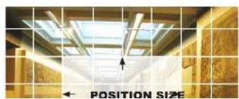
natural_image
Interior view of a modern building with ceiling skylights and a highlighted position size arrow (no text or symbols on the main structure)
natural_image
Interior view of a modern building hallway with ceiling skylights and wooden flooring (no visible text or symbols)③ Move the arrow indicator to WIDTH to make desired width of cells to increase or decrease by using the Left / Right button between the level 0 \~ 100.
④ Move the arrow indicator to HEIGHT to make desired height of cells to increase or decrease by using the Left / Right button between the level 0 \~ 100.
⑤ Move the arrow indicator to the LEFT / RIGHT and TOP / BOTTOM to select the desired area position by using the LEFT or RIGHT button.
⑥ Move the arrow indicator to COLOR to select the desired color of each area cells by using the Left / Right button to select between the 15 different color.
RETURN : Move the arrow indicator to RETURN after completing the setup to return to SPECIAL menu.
4-3) SYNC : INT (Internal Synchronisation)
Move the arrow indicator to RETURN after complete the setup to return to SETUP menu.
- DEFECT
You can eliminate white spots (defect) up to max 128 point.
SENSE-UP : To eliminate defect, set the high level of sense-up. You can set to max 64x, but 32x is best to eliminate defect.
ADJUST
- When the SETUP menu screen is displayed, select ADJUST using the Up and Down buttons.

text_image
SETUP 1.LENS DC 2.EXPOSURE 3.WHITE BAL ATW 4.DAY / NIGHT AUTO 5.3DNR ON 6.SPECIAL 7.ADJUST 8.RESET 9.EXIT- Select the desired mode by using Up or Down button..

text_image
ADJUST SHARPNESS 20 MONITOR LCD ← RETURN RET ←RESET
Resets the camera settings to the factory defaults.
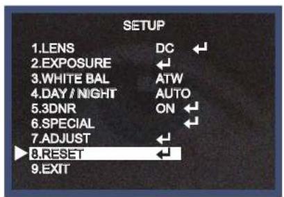
text_image
SETUP 1.LENS DC 2.EXPOSURE 3.WHITE BAL ATW 4.DAY / NIGHT AUTO 5.3DNR ON 6.SPECIAL 7.ADJUST 8.RESET 9.EXIT
text_image
RESET FACTORY RETURN RETEXIT
Press the SET button in the EXIT menu to save the current settings and exit the SETUP menu.
Trouble Shooting
| PROBLEM | POSSIBLE CAUSE |
| Northing appears on the screen. | Check the power cable, power supply output and video connection between the camera and monitor. |
| The image on the screen is dim. | Are the camera lens or the lens glass dirty?Clean the lens / glass with a soft clean cloth.Adjust the monitor controls, as required.If the camera is facing a very strong light, change the camera position.Adjust the lens focus. |
| The image on the screen is dark. | Adjust the contrast control of the monitor.If there is an intermediate device, correctly set the 75Ω/Hi-z. |
| The camera is not working properly and the surface of the camera is hot. | Check the camera is correctly connected to an appropriate regulated power source. |
| Motion Detection | Has MOTION DET been set to ON in the menu? |
speco technologies®
PRODUCT WARRANTIES AND INFORMATION EFFECTIVE JULY 8, 2008
POLICY. TERMS AND CONDITIONS OF SALE
This statement of policy is in lieu of any other policy, expressed or implied, and no representative or person is authorized to assume for us any other liability or policy without our written consent. We cannot be held responsible for typographical errors.
TERMS OF PAYMENT
2%, 10 days, not 30 from invoice date of merchandise for qualified accounts or Visa/MasterCard/Amex net at time of order placement only, other payment discounts do not apply (\$300 credit card minimum). We reserve the right to charge 1-1/2% interest per month on past due balances. New orders will not be shipped while there is a past due balance. We will also ship net C.O.D. or C.I.A.
PRICING POLICY
This price sheet reflects current published price. All prices are subject to change without notice. All items will be billed at current prices.
CREDIT
Companies that have not established credit with our company should allow a sufficient period of time for credit approval. Please be sure to provide complete credit information, bank and trade references, plus financial statements, if available with your first order. To expedite first shipment, a certified or bank check with the order or use of Visa/MasterCars/Amex will avoid delays, while we are checking credit and waiting forbankclearance.
FREIGHT POLICY
All shipments are F.O.B. our New York warehouse. All orders totaling \$2000 or more will be shipped freight allowed to any point in zones 1,2,3,4,5 and 1/2 freight allowed in zones 6,7,8, providing invoice is paid within 30 days from receipt of merchandise, catalogs or exceptions from regular pricing. All UPS and USPS shipments will be insured with insurance fee plus shipping and handling charges added to the invoice.
MINIMUM OPENING ORDER \$1500
We reserve the right to refuse recorders under \$250. PLEASE REQUEST CONFIRMATION OF ALL FAXED PURCHASE ORDERS.
WARRANTY
| VIDEO | Cameras | 5 Years |
| Monitors & IR LEDs | 1 Year | |
| DVRs / EZVR Series VDRs | 3 Years | |
| PCPro / PCL Series DVRs | 2 Years | |
| AUDIO | IndoorSpeakers | Lifetime |
| Outdoor/WeatherproofSpeakers | 5 Years | |
| Amplifiers | 5 Years | |
| PA Horns, Microphones,VolumeControls | 2 Years | |
| Megaphones,Speaker Distribution CentersandSpeakerSelectors | 1 Year | |
| TechnicalEquipmentNot ListedAbove & BalanceLine | 90Days |
We warranty all products to be free from any manufacturing or material defects. This warranty will not extend to any product which have been subjected to misuse, neglect, accident, or improper installation, used in violation of instructions furnished by us; or to units which have been repaired or altered outside of the factory. This limited warranty does not apply to broken cases, batteries, or other physically damaged parts. Upon request by the customer, the company will of the customer's expense repackage merchandise in new cartons, replace missing accelsatories, and return in reliable information about its products. The company is not a liability for any loss arising from the packaging in which it was received. This warranty is in lieu of all expressed warranties, expressed or implied and of all obligations or liability on our part and we neither assume nor authorize any representative or other person to assume for us any obligation or liability. In no event shall we be liable for incidental or consequential damages arising from the use of the product, or for any delay in the use of this product do to causes beyond our control. Some states do not allow limitations of how long an implied warranty lasts and/or do not allow the exclusion or limitation of consequential damages. We above limitations on implied warranty and consequently warranties may not apply to the risks of legal rights. You may have other rights which vary from state to state. See actual warranty statement included with product for limitations and exclusions where applicable. This limited warranty extends to product listed in the company's current priceschedule.
RETURNS
- MEMO -
- MEMO -
speco technologies®
200 New Highway
Amityville, NY 11701
631-957-8700
1 800 645 5516
www.specotech.com