Intensifier IP OIMD1W - Security Camera Speco Technologies - Free user manual and instructions
Find the device manual for free Intensifier IP OIMD1W Speco Technologies in PDF.

User questions about Intensifier IP OIMD1W Speco Technologies
0 question about this device. Answer the ones you know or ask your own.
Ask a new question about this device
Download the instructions for your Security Camera in PDF format for free! Find your manual Intensifier IP OIMD1W - Speco Technologies and take your electronic device back in hand. On this page are published all the documents necessary for the use of your device. Intensifier IP OIMD1W by Speco Technologies.
USER MANUAL Intensifier IP OIMD1W Speco Technologies
Intensifier IP® Full HD Megapixel Indoor/Outdoor
Miniature Turret IP Camera

natural_image
Exterior view of a white spherical device labeled 'Speca technologies' with a smaller rectangular component nearby (no additional text or symbols visible)Directions
Be careful not to cause any physical damage by dropping or throwing the camera. Especially keep the device out of reach from children.
Do not disassemble the camera. No after service is assumed when disassembled.
Use only power adapters compatible with the unit.
Be careful to prevent moisture or water penetration into the unit. Particular attention is needed when installing the unit. The screw holes for the installation screws and pipe should be maintained water tight during the whole life time of the product.
All the electrical connection wires running into the unit should be prepared so that water from the outside cannot flow into the unit through the surface of the wires. Penetration of the moisture through the wire for extended period can cause malfunction of the unit or deteriorated image.
Note
This equipment has been tested and found to comply with the limits for a Class A digital device, pursuant to part 15 of the FCC Rules. These limits are designed to provide reasonable protection against harmful interference in a residential installation. This equipment generate, uses and can radiate radio frequency energy and, if not installed and used in accordance with the instructions, may cause harmful interference to radio communications. However, there is no guarantee that interference will not occur in a particular installation. If this equipment does cause harmful interference to radio or television reception, which can be determined by turning the equipment off and on, the user is encouraged to try to correct the interference by one or more of the following measures:
● Reorient or relocate the receiving antenna.
■ Increase the separation between the equipment and receiver
Revision History
| Date Revision Details | ||
| Feb 25 ^th , 2014 | 1.0 First manual | revision creation. |
Contents
- Introduction......5
1.1. Overview 5
1.2. Specifications....6
1.3. Applications of O2iMT61....8
- Product Description 9
2.1. Contents....9
2.2. Product Preview....9
2.3. Physical description 10
2.3.1. External View....10
2.3.2. Dimensions....10
2.3.3. Front and Rear view of Encoder box 11
2.3.4. Factory Default Switch....11
2.4. Functional Description 12
- On Site Installation 14
- Getting Started....16
4.1. PC Requirement 16
4.2. Quick Installation Guide....17
4.2.1. Connect PC and O2IMT61 to network....17
4.2.2. Install Speco-NVR and set IP parameters on O2IMT61....17
A 2 3 Remote video connection to O2IMTA1 19
1. Introduction
1.1. Overview
The ONSIP O2iMT61 is a state-of-the-art mega-pixel, dual-codec (H.264, MJPEG) IP/network camera built with embedded software and hardware technology. It enables real time transmission of synchronized video of Full HD resolution and audio data. Remote clients can connect to ONSIP O2iMT61 for the real time video/audio data through various client solutions running on PC, PDA or mobile phones. Real time 2-way communication is available through bidirectional audio communication feature.
Intensifier IP® technology is the most optimized solution for indoor and outdoor surveillance in low-light conditions by using superior CMOS sensor with low-light sensitivity ISP sensor. Intensifier IP® is especially beneficial in poor lighting environments, efficiently reducing noise and ghosting while maintain a color image without the use of IR LEDs.
Designed to be a stand-alone streaming audio & video transmission device, ONSIP O2IMT61 can be applied to various application area such as video security, remote video monitoring, distance education, video conference or internet broadcasting system.
The separate encoder box and camera design allows for smaller camera housing and flexibility in installations. The camera portion is vandal and weather resistant, which allows it to be installed in outdoor settings, while the encoder box can be hidden from view. Embedded PoE (Power over Ethernet, IEEE 802.3af) will enable the owner to reduce the total cost of ownership by reducing on-site wiring works for the installation.
1.2. Specifications
| Camera | |
| Image sensor Progressive scan 1/3 inch CMOS 2M pixels | |
| Full resolution 1,920 x 1,080 pixels (Full HD) | |
| Sync System Internal | |
| Lens 2.9mm fixed (3.6mm, 6mm optional) | |
| Day & Night AUTO, DAY, NIGHT | |
| Sensitivity Intensifier Max - 0.0005 Lux | |
| Back Light Compensation ON / OFF | |
| White Balance ATW(2.000K ~ 10,000K) / MANUAL / PUSH | |
| Exposure DC / ESC | |
| WDR ON / OFF | |
| 3D-DNR | 0 ~ 20 |
| Intensifier | AUTO ON (Max 128x) / OFF |
| Privacy Mask | ON / OFF (10 Programmable Zones) |
| Motion Detection | ON / OFF (4 Programmable Zones) |
| Digital Zoom | 1x ~ 12x |
| Mirror | H / V / Rotate |
| DEFOG | ON / OFF |
| OSD BUILT IN | |
| Video | |
| Compression method | Simultaneous Dual Codec (H.264 / MJPEG) |
| Network | |
| Network Protocol | - IPv4, TCP, UDP, IGMP, ICMP, ARP, RARP, PPPoE, RTCP- RTP, RTSP, SDP, HTTP, SMTP, FTP, DHCP, UPnP- NTP, DNS, DynDNS |
| Dynamic IP Speco DDNS (free of charge) | |
| Security | - User ID & Password protection, IP address filtering- Digest Authentication, User Access Log |
| Streaming method | - RTSP streaming with proprietary format for control information-standard RTSP streaming- HTTP streaming |
| External Terminals | |
| LAN 10/100BaseT LAN (auto MDIX) | |
| Alarm input / output Alarm I/O (1 Sensor Input & 1 Relay output) | |
| Factory Reset Supported | |
| Audio MIC/Line in, Line out | |
| Power DC 12V input | |
| Alternate Power | |
| Standard PoE IEEE802.3af Supported | |
| Alarm & Event | |
| Intelligent Video Motion Detection | |
| Alarm Triggers Motion Detection + Sensor Input | |
| Alarm Events | Video file upload(FTP), Still Image transmission(Email), Relay output |
| Alarm Buffer (Audio\Video) | Configurable Pre-alarm (5~15 sec) & Post alarm (10~60 sec) |
| Client Software | |
Space NVR
Windows XP/Victa/7 (free of charne)
1.3. Applications of O2iMT61
• Security surveillance (buildings, stores, manufacturing facilities, parking lots, banks, government facilities,
military, etc.)
- Remote monitoring (hospitals, kindergartens, traffic, public areas, etc.)
• Teleconference (Bi-directional audio conference). Remote Learning, Internet broadcasting
• Weather and environmental observation
2. Product Description
2.1. Contents
The product package contains followings :
| Contents | Description | Remarks |
| O2iMT61 | O2iMT61 main and camera units | 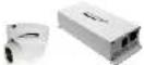 |
| Accessories | Screws (1 type) |  |
| Anchors (1 type) |  | |
| L-type wrench |  | |
| Cable bracket and Screw |  | |
| CD | Software & User's Guide |  |
| Reference Guide | Quick installation guide, Guide pattern | [70X9] |
2.2. Product Preview
2.3. Physical description
2.3.1. External View

natural_image
Two white industrial devices: a white pipe fitting and a white electronic device with ports and connectors (no visible text or symbols)Figure 2-1. External view of O2iMT61
2.3.2. Dimensions
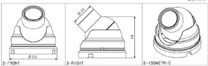
Unit: mm
2.3.3. Front and Rear view of Main Unit

text_image
Cable bracket screw hole Pin De 1 Lin 2 GroundFigure 2-3. Front view
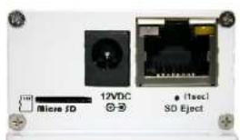
text_image
Micro ID 12VDC SD Eject (1sec)| Pin | Description |
| 1 | Line Output |
| 2 Ground | |
| 3 MIC/ | Line Input |
| 4 | Relay Output |
| 5 Relay | Output |
| 6 Sensor Input | (-) |
| 7 Sensor Input | (+) |
| Connect Camera | Connect Camera Unit |
Figure 2-4. Rear view
2.3.4. Factory Default Switch
Factory default switch is provided for returning the IP camera to factory default state.
There are two functions assigned to factory default switch.
- Returning to Factory Default State : Press the switch about 5 seconds while power is applied to return to factory default state.
- Safe Removal of Micro-SD Card : Press the switch for 1 second to unmount Micro-SD Card for sale removal.
2.4. Functional Description
• Power : Power input for supplying 12V DC power.

Caution : If O2iMT61 is powered by PoE, do not plug in DC Jack with active DC power Into DC power connector.
- Network (LAN)
100Mbps Ethernet connector (RJ-45) with PoE standard (802.3af). LED on the Ethernet connector shows the status of O2iMT61 as follows:
- Link LED
It will be lit with orange color when network cabling is all right. Blinking orange color indicates that normal data transmission is under way. Off state indicates that there is trouble in network connection
- Status LED ( It will be lit in green or red depending on the status)
① Green : Green color indicates that the camera is in normal operation mode. Continuous green indicates that data transmission is possible. Blinking green means that someone is connected to Q2iMT61.
② Red : Continuous or blinking red indicates that hardware is in abnormal condition.

LED will be lit with red momentarily and it will be lit with green after a while when power is applied into O2iMT61
- Micro SD Card slot
Please insert SD memory card when you want to use SD memory card. In case of pulling out SD memory
- Sensor Input
Connect external alarm sensor. Examples of sensing devices are infrared sensor, motion sensor, heat/smoke sensor, magnetic sensor, etc. Connect the two wires of the sensors to "Sensor Input". The sensor type (NC/NO) can be set in admin page. Multiple sensor devices can be connected in parallel

flowchart
graph TD
    A["Photo Coupler"] --> B["Sensor1+"]
    B --> C["NO/NC Type Open Collector Type"]
    C --> D["Sensor Device"]
    D --> E["Sensor Power Supply"]
    C --> F["Sensor Device"]
    F --> G["Sensor Power Supply"]
    H["GND"] --> I["+12V"]
    style A fill:#f9f,stroke:#333
    style C fill:#ccf,stroke:#333
Figure 2-6. SENSOR Input and connection of the sensor
- Relay Output
Relay output is provided for connecting alarm devices or for remote on/off control of devices such as light. Relay is normal open and it will be closed upon alarm annunciation or remote on. The relay is capable of switching 30V AC/DC, 2A. For the application which needs power switching beyond this limit, use additional relay switch as shown in the right of Figure.

3. On Site Installation
Use cables and conduits that are suitable for the installation. Particular attention should be paid in the installation so that no moisture is allowed to penetrate into the unit through the cables or conduits during the life time of the product. Products of which the internal parts are exposed to moisture because of improper installation are not covered by warranty

text_image
1. Unscrew bolt to separate camera from bracket- Insert the wire through the ceiling or wall hole, and fix the bracket to the ceiling or wall with the mounting screw.

text_image
3. Adjust the camera to receive desired video image, and screw the bolt to fix the camera.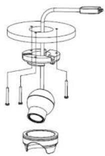
natural_image
Technical line drawing of a mechanical assembly with no visible text or symbols- Fix the connecting wire from the camera to the main unit by using the cable bracket.
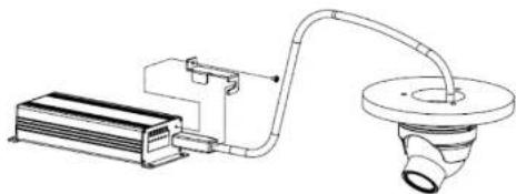
natural_image
Technical line drawing of a mechanical device with a cooling unit and pipe fitting (no text or symbols)- Connect the power cable and LAN cable to the main unit.

natural_image
Technical line drawing of a rectangular electronic component with two connected probes (no text or symbols)4. Getting Started
Brief information for first time operation of O2iMT61 is provided in this chapter.
4.1. PC Requirement
Audio/Video streaming data received from O2IMT61 can be displayed or stored in a PC running client programs. Minimum requirement of the PC is described below:
| ITEM Minimum Requirement Recommended Specification | ||
| CPU Intel Core i3 3Ghz Intel Core i7 | ||
| Main Memory 2GB 4GB | ||
| Operating System Windows XP Windows 7 (64bit) | ||
| Web Browser Internet Explorer 8, 9 Internet Explorer 8, 9 | ||
| Graphic Card | Video RAM 256MBResolution 1920x1080 | Video RAM 1GBHigher than 1920x1080 |
| Network 10 Base-T Ethernet 100 Base-T Ethernet | ||
* Operating Systems supported: Windows 2000 Professional, Windows XP / Vista / 7
4.2. Quick Installation Guide
4.2.1. Connect PC and O2iMT61 to network.
- Prepare a PC to run programs for the installation and video connection (PC is needed to assign IP address to O2iMT61)
- In the case of using PoE, connect the PC and O2iMT61 to the network using one of the following ways. If your LAN Switch does not support standard PoE, connect O2iMT61 as shown in dotted line in Figure. The DC power is applied through DC adapter.
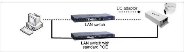
flowchart
graph LR
    A["Computer"] --> B["LAN switch"]
    B --> C["LAN switch with standard POE"]
    C --> D["Device with DC adaptor"]
    D --> B
Figure 4-1. Power and network connection
4.2.2. Install Speco-NVR and set IP parameters on O2iMT61
Speco-NVR is a multi-channel VMS program for the IP camera. Install Speco-NVR on remote PC to connect to these products. It is needed to assign connection information to Speco-NVR program before connection. Insert the CD provided with product into the PC and install Speco-NVR.

Follow the sequence below for setting the IP parameter
i) Run ONSIP installer
II) Click (1) In ONSIP Installer window.> Double click on (2) > Fll in (4) > make a selection in (5) > Fll the parameters in (6)
iii) Click on (9) to apply the settings.
iv) You can connect to admin page by clicking on (10).

text_image
IP Installer MAC Address IP Address Name No Refresh Set Admin: Port Reboot Default Adapter About Exit 1 2 3 4 5 6 7 Net, Mode Static System Name Web Port RTSP Port Management Server HTTP Streaming Clone MAC Static ADSL(PPPoE) Auto(DHCP) WLAN Radio 802.11b WLAN SSIO Auth. Type EncryptType WLAN Key IP Address Subnet Mask: Gateway DNS1 DNS2 Service Name User Name Password4.2.3. Remote video connection to O2iMT61
- Connection through Web Viewer
Web Viewer offers simplest way of video connection to O2IMT61. For video connection, enter the IP address of O2IMT61 In the URL window of Internet Explorer as:
[e.g.] Port 80
http://172.16.64.133/
Default port 80 can be omitted
[e.g.] Port 8080
http://172.16.64.133:8080/

Note : Active-X module should be installed on your PC before actual connection. If your PC is not connected to the internet, you cannot download Active-X module. Most convenient way of installing the Active-X module is installing Speco-NVR which is available from the CD or our web site.
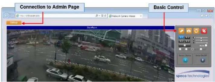
text_image
Connection to Admin Page Basic Control Setup SeeForm speco technologies2. Connection through Speco-NVR
Click the camera assignment button for settling the camera address. Input the description, address, Ch#, User ID. Password and port and then click the save button. After assignment procedure, you must click the SAVE button. You can see the live video when you click the live view button as below. When you exit Speco-NVR, you have to input the ID/PW, admin/1234. Details for Speco-NVR can be found in [Speco-NVR User's Guide].
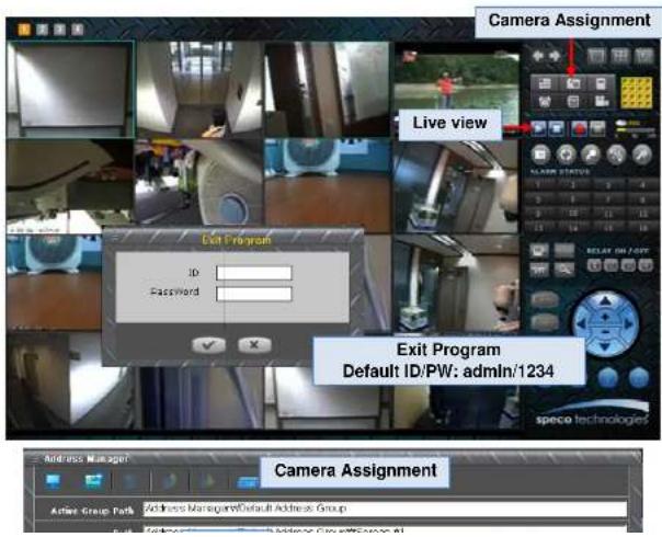
text_image
Camera Assignment Live view Exit Program ID Password Exit Program Default ID/PW: admin/1234 speco technologies Address Manager Camera Assignment Active Group Park Address Manager/Default Address Group4.2.4. Additional settings through connection to the Admin Page
All parameters of the camera are factory default out of the box. For a more sophisticated target application, parameters need to be changed through the admin page. The admin page can be connected through
"http://IP Address:Port Number/admin.htm"
ID and password of the administrator are required. Default ID and password are "admin", "1234". It is highly recommended to change the ID and password to prevent illegal access to the IP camera. For more detailed information, Please refer to the "Configuration Guide".
5. Troubleshooting
5.1. No power is applied
- In case of Standard PoE (Power over Ethernet)
Power supply through standard PoE is possible only when the following conditions are met.
- Standard PoE is supported on the product.
- The LAN switch supports standard PoE.
Make sure that both the IP camera and the LAN switch support standard PoE (IEEE 802.3af)
- In case of DC adapter
If PoE is not applied, the power and network connection should be made through separate cables.
It is recommended to use DC adapter supplied by provider for the feeding of the power. In case of replacing the DC power supply, make sure that the power supply meets with the power requirement of the IP camera to prevent damage or malfunction.
5.2. Cannot connect to the Video
Check the status of the network connection through PING test.
Try the following on your PC :
- Start > Run > Cmd > Ping IP address (Ex : Ping 172.16.42.51)
- If "Reply from \~" message is returned (1 in the figure below), the network connection is in normal state. Try connection to the video again. If the problem persists, or refer to other trouble shooting notes.
- If "Request timed out" message is returned. (② in the figure below), the network connection or network setting is not in normal state. Check the network cable and settings.
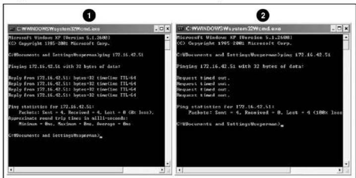
text_image
C:\WINDOWS\System32\cmd.exe Microsoft Windows XP (Version 5.1.2600) © Copyright 1985-2001 Microsoft Corp. C:\Documents and SettingsMugerman\ping 172.16.42.51 Playing 172.16.42.51 with 32 bytes of data: Reply from 172.16.42.51: bytes=32 timeline TTL=64 Reply from 172.16.42.51: bytes=32 time(tim TTL=64 Reply from 172.16.42.51: bytes=32 time(tim TTL=64 Reply from 172.16.42.51: bytes=32 time(tim TTL=64 Play statistics for 172.16.42.51: Packet: Sent = 4, Received = 4, Lost = 8 (8x loss), Approximate round trip times in alli-seconds: Minimum = Max, Maximum = Max, Average = Max C:\Documents and SettingsMugerman>5.3. Windows Vista or Windows 7
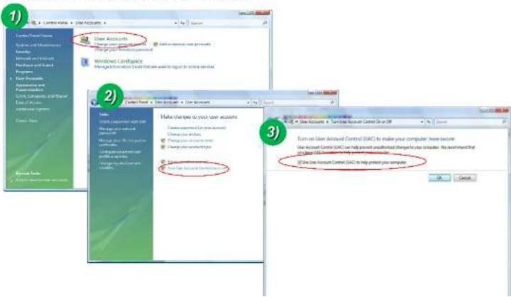
Windows Vista and Windows 7 users need to configure UAC (User Access Control) and Privilege Level for proper recording and still video capture in Speco-NVR and Web Viewer.
- UAC (User Access Control) configuration
1) Double-click "User Accounts" in control panel
2) Double-click "Turn User Account Control on or off"
3) Uncheck "Use UAC to help protect your computer"
text_image
1) User Accounts Manage your own accounts Add to account new accounts Windows Control Interface Manage Information Card that are used to report to create services 2) Make changes to your save accounts Change your account Change your account Change your account 3) Turn on User Account Control (DAC) to make your computer's more secure User Account Control (DAC) can help prevent unauthorized change to your computer. My recommendation that is the user Account Control (DAC) to help protect your computer. OK Cancel
text_image
Open Troubleshoot compatibility Open file location Run as administrator Pin to Taskbar Pin to Start Menu Restore previous versions Send to Cut Copy Create shortcut Delete Rename Properties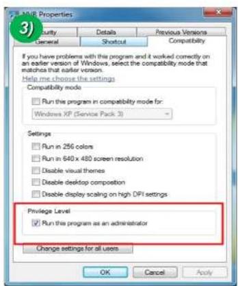
text_image
AMD Properties Security Details Previous Versions General Shout Compatibility If you have problems with this program and it worked correctly on an earlier version of Windows, select the compatibility mode that matches that earlier version. Help me choose the settings Compatibility mode Run this program in compatibility mode for: Windows XP (Service Pack 3) Settings Run in 256 colors Run in 640 x 480 screen resolution Disable visual themes Disable desktop composition Disable display scaling on high DPI settings Privilege Level Run this program as an administrator Change settings for all users OK Cancel Apply- UAC (User Access Control) configuration
1) Double-click "User Accounts" in control panel
2) Double-click "Change User Account Control setting"
3) Set to "Never notify"

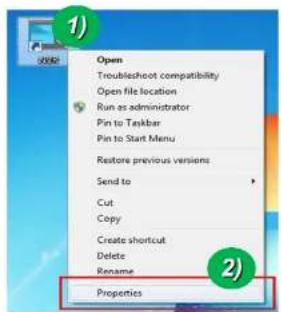
2. Privilege Level Control
1) Select "NVR" icon on the desktop
2) Click right mouse button and select "properties"
3) Check "Privilege Level" in "Compatibility" tab
text_image
1) Open Troubleshoot compatibility Open file location Run as administrator Pin to Taskbar Pin to Start Menu Restore previous versions Send to Cut Copy Create shortcut Delete Rename Properties
text_image
MVR Properties Security Details Previous Versions General Shortcut Compatibility If you have problems with this program and it worked correctly on an earlier version of Windows, select the compatibility mode that matches that earlier version. Help me choose the settings Compatibility mode Run this program in compatibility mode for: Windows XP (Service Pack 3) Settings Run in 256 colors Run in 640 x 480 screen resolution Disable visual themes Disable desktop composition Disable display scaling on high DPI settings Privilege Level Run this program as an administrator Change settings for all users OK Cancel ApplyO2IMT61 User's Guide
5.4. Technical Assistance
If you need any technical assistance, please contact technical support. For immediate service please provide the following information.
Model name
MAC address and Registration number
Purchase date
Description of the problem
Error message
Appendix A – Important Notice in Exchanging SD Card (Micro SD)
SD Card is a non-volatile memory device for storing video and audio data on the product. Note that continuous recording to the SD Card will cause the memory cell to wear out, eventually resulting in failure.
When you plug out the SD Card for replacement or other purpose, follow the steps below in order to prevent data loss or crash of the SD Card.
- Press factory default button for 1 sec to unmount the SD Card.
- SD Card can also be unmounted by going to Admin Page -> Sensor&Capture Setup and clicking on CONFIRM button at the right of SD Card Unmount menu.
- Unplug the SD Card
- If no action is taken within 1 minute, SD Card will be mounted again.
- Plug in new SD Card
- If the SD Card is a new one for the IP camera, format the SD Card by following through the steps below.
- Go to Admin Page -> Sensor & Capture Setup
- In the SD Card management menu, click on CONFIRM button at the right of SD Card Format.
For more detailed information regarding connection to admin page, please refer to the "Configuration Guide".