ZIPK88B2 - Security Camera Speco Technologies - Free user manual and instructions
Find the device manual for free ZIPK88B2 Speco Technologies in PDF.

User questions about ZIPK88B2 Speco Technologies
0 question about this device. Answer the ones you know or ask your own.
Ask a new question about this device
Download the instructions for your Security Camera in PDF format for free! Find your manual ZIPK88B2 - Speco Technologies and take your electronic device back in hand. On this page are published all the documents necessary for the use of your device. ZIPK88B2 by Speco Technologies.
USER MANUAL ZIPK88B2 Speco Technologies
text_image
speco technologies®User Guide (Ver. 1.4)
Models: ZIPKIT
Network Video Recorder and IP Camera


Cautions

CAUTION: TO REDUCE THE RISK OF ELECTRIC SHOCK, DO NOT REMOVE COVER (OR BACK). NO USER SERVICEABLE PARTS INSIDE. REFER SERVICING TO QUALIFIED SERVICE PERSONNEL.
Explanation of Graphical Symbols

This symbol indicates the presence of important operang and maintenance (servicing) instrucons in the literature accompanying the product.

This symbol indicates the presence of "dangerous voltage" within the product's enclosure that may be of sucient magnitude to constute a risk of electric shock, property damage, personal injury, or death.
These precautions must be followed for safety reasons

Warning
- Do not use if the unit emits smoke.
- Do not disassemble the unit.
- Do not place any heavy or sharp objects on the unit.
- Do not place on uneven surface.
- Do not expose to shock or vibration.
- Do not move the unit when the unit is powered on.
- Do not block, and allow dust to accumulate in the air vents.
- Do not restrict airflow of the unit; doing so can damage the unit.
- Only qualified and experienced personnel should perform installation and servicing.
- Turn off the power of the ZS when connecting Cameras, Audio or Sensor Cables.
- The manufacturer is not responsible for any damage caused by improper use of the product or failure to follow instructions for the product.
- The manufacturer is not responsible for any problems caused by or resulting from the user physically opening the ZS for examination or attempting to repair the unit.
Product Components
Please make sure the following components are included as specified below.
| Desktop:NxZS | |
| Bundle IP Camera(PoE) 4 EA | |
| Remote Control | 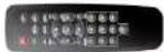 |
| Battery 1.5V (AAA x 2 EA) |  |
| Quick Setup Guide &User Guide |  |
| Mouse for NxZS |  |
| Software & Manual CD |  |
Specifications
| MODEL | N4ZS | N8ZS | ||
| Video | Input | IP Cameras | 4 | 8 |
| Max Bit Rate | 20Mbps | 20Mbps | ||
| Resolution | Max. 1920x1080 | |||
| Output | Main Monitor | VGA and HDMI | ||
| Sub Monitor | CVBS (BNC) | |||
| Audio | Input | IP Cam Audio | 4 | 8 |
| RCA Input | 4 | 4 | ||
| Output | RCA Output | 1 | ||
| Audio Codec | G.711 | |||
| Event | Sensor In | IP Cam Sensor | 4 | 8 |
| Local Input | 4 (Terminal Block) | |||
| Local Alarm Output (Terminal Block) | 1 | |||
| IP Camera Motion Detection | Yes | |||
| Serial | RS-232C | Yes | ||
| RS-485 | Yes | |||
| Network | Private (IP Camera, Auto Connection) | 4 Port PoE | 8 Port PoE | |
| LAN (Remote Access, IP Camera) | 10/100 Base-T | 10/100 Base-T | ||
| Protocols | TCP/IP, UDP, DHCP, HTTP, NTP, SMTP, RTP, RTSP | |||
| Compression | H.264 (Baseline, Main, High Profile) | |||
| Resolution & Frame Rate | D1 | 120fps | 240fps | |
| 1280x720 | 120fps | 240fps | ||
| Features | Dynamic DNS | Yes (Free Speco DDNS) | |
| Digital Zoom | Yes | ||
| DLS (Day Light Savings) | Yes | ||
| NTP (Network Time Protocol) | Yes | ||
| S.M.A.R.T. | Yes | ||
| Internal Beep | Yes | ||
| Multi-Language | Yes | ||
| e-mail Notification | Yes | ||
| Network Access | 3G Mobile | iPad / iPhone / Android | |
| Web Viewer | Windows (IE, Chrome, Firefox, Safari) | ||
| PC Client | Multi Client | ||
| Remote Setup and Upgrade | Yes | ||
| Power | Power Supply Voltage | DC12V 5A & DC48V 1A | DC12V 5A & DC48V 2A |
| Temperature | Operating Temperature | 41°F ~ 104°F (5°C ~ 40°C) | |
| Storage Temperature | 14°F ~ 122°F (-10°C ~ 50°C) | ||
| Weight | Desktop Unit Weight (Gross weight) | Approximately 12 lbs | |
| Dimension | Unit Dimension (W x D x H) | 13.5"W x 10.3"D x 2.5"H | |
Please note that specifications and unit exterior design are subject to change without notification.
Table of Contents
- Main Features 10
- Initial Boot-up Process....11
2-1. Initial Boot up and Basic Time Setup.... 11
2-2. Setting up Daylight Savings Time....12
2-3. Setting NTP (Network Time Protocol)....13
2-4.EZ SETUP 16
2-5. PoE Port SETUP....19
2-6. IP Camera SETUP (through SpecoTech Web Viewer)....20
2-7. Dual Streaming....21
- Front and Rear Panels 22
3-1. Desktop Front Panel 22
3-2. Connectors 22
3-3. Remote Control....23
- Setting up the ZS.... 24
4-0. Setup – Main Live Screen....24
4-1. Setup – IP CAMERA....25
4-1-1. SCAN Menu....27
4-2. Setup – SYSTEM....28
4-3. Setup – RECORD Mode .... 32
4-4. Setup - DEVICE Mode ....34
4-4-1. Digital Deterrent....36
4-5. Setup - DISPLAY Mode 37
4-6. Setup – NETWORK Mode....38
4-6-1. Network Types 39
5-3-5. Go To Last Time....55
5-3-6. Go To Specific Time ....55
5-3-7. Archive List 55
5-3-8. Log List....56
5-4. Play Mode....56
- Back Up....58
6-1. Video Backup onto USB Flash Drive during playback 58
6-2. EZCopy: Video Backup onto USB Flash Drive during playback....59
6-3. Transferring Still Images or Video from the ARCHIVE List....60
6-4. Playback of Backup Video....61
6-5-1. AVI Format....61
6-5-2. NSF Format 61
- Network Access Using the Multi-Sites Network Viewer 62
7-1. Overview 62
7-2. PC Requirements....62
7-3. Installation of the Program 63
7-4. Live Window....64
7-4-1.Main User Interface....64
7-4-2. Control Buttons....64
7-5. Search and Playback Window....65
7-5-1.Main User Interface....65
7-5-2. Main Control Panel 66
7-6. Setup of SpecoTech Multi Client....67
7-6-1. General....67
7-6-2. Event 68
7-6-3. Record....69
7-8-1. Addition, Delete, and Modify ZS Sites 82
7-8-2. Connect and Disconnect....84
7-8-3. Still-Image Capture During Live....85
7-8-4. Recording Video on Local PC During Live 85
7-8-5. Local Playback and Remote Playback 87
7-8-6. AVI Backup during Playback 89
7-9. ZIP IP Camera Setup 91
7-9-1. Live View 91
7-9-2. Video 92
7-9-3. Security....92
7-9-4. Event 93
7-9-5. Network 93
7-9-6. System....94
-
Network Access Using SpecoTech Web Viewer....96
-
Network Access Using the Smart Phone Viewer 98
9-1. App Viewer for iPhone....98
9-1-1. Live....98
9-1-2.PTZ Control 100
9-1-3. Playback....100
9-2. App Viewer for Android Phone....101
9-2-1. Live....101
9-2-2. Playback....102
9-2-3. PTZ Control 103
APPENDIX: Network Connection - LAN.... 103
APPENDIX: Network Connection – Internet and DDNS 106
1. Main Features
■ Automatic IP Camera Detection and connection (Plug & Play)
■ Easy Record, Copy and Setup
■ Easy Search by Thumbnail Preview
■ Easy Copy
■ Easy Network
■ Easy IP Camera Setup
NOTE: Under federal law, The Fourth Amendment to the U.S. Constitution, Title III of the Omnibus Crime Control and Safe Streets Act of 1968, as amended by the Electronic Communications Privacy Act of 1986 (18 U.S.C. § 2510, et seq.), and the Foreign Intelligence Surveillance Act of 1978 (50 U.S.C. 1801, et seq.) permit government agents, acting with the consent of a party to a communication, to engage in warrantless interceptions of telephone communications, as well as oral and electronic communications.
■ Covert camera operation provides enhanced security and administrator control
■ Dynamically programmable recording priority, motion detection, alarms and scheduling
■ Simple and Easy Graphic User Interface
■ Simple Scheduler
■ HDMI Output
■ VGA Output
■ Password to secure installation authorization
■ Network software supports 10/100Mbps
■ USB 2.0 port for video clip exporting and easy firmware upgrade via USB Flash Drive
2. Initial Boot-up Process
2-1. Initial Boot up and Basic Time Setup
- During the first boot up, the following logo will be displayed.

text_image
speco technologies- After the logo, select the language and set date and time as specified below.

text_image
CHOOSE LANGUAGE ENGLISH < PREV NEXT > CLOSE
text_image
Initializing system It may take a few seconds or minutes to check the system 90% Initialize Network...Done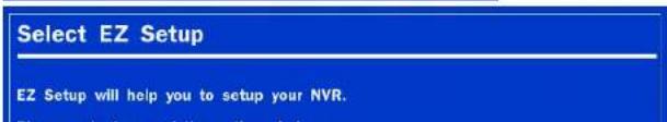
text_image
Select EZ Setup EZ Setup will help you to setup your NVR.2-2. Setting up Daylight Savings Time
To enable Daylight Saving feature/NTP synchronization, take the following steps.
- Enter the SETUP mode. The default Username is "ADMIN" and Password is "1111".
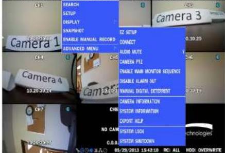
text_image
SEARCH SETUP DISPLAY SNAPSHOT ENABLE MANUAL RECORD ADVANCED MENU CZ SETUP CONNECT AUDIO MUTE CAMERA PTZ ENABLE NAR MONITOR SEQUENCE DISABLE ALARY OUT MANUAL DIGITAL DETERMENT CAMERA INFORMATION SYSTEM INFORMATION CAPSIT HELP SYSTEM LOCK SYSTEM SHUTDOWN CAMERA 3 0.30:20 0.30:20 0.30:20 0.30:20 0.30:20 0.30:20 0.30:20 0.30:20 0.30:20 0.30:20 0.30:20 0.30:20 0.30:20 0.6/29/2013 15:42:10 R/C: ALL HDD: OVERWRITE
text_image
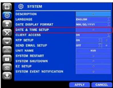
LOGIN - SETUP USER ADMIN PASSWORD OK CANCEL- Go to SETUP > SYSTEM > DATE & TIME SETUP
text_image
SYSTEM DESCRIPTION LANGUAGE DATE DISPLAY FORMAT DATE & TIME SETUP CLIENT ACCESS NTP SETUP SEND EMAIL SETUP UNIT NAME SYSTEM RESTART SYSTEM SHUTDOWN EZ SETUP SYSTEM EVENT NOTIFICATION ENGLISH MM/DD/YYYY ON ON OFF NVR APPLY CANCEL- Select ON from the DAVLIGHT SAVING dropdown menu
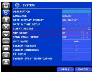
2-3. Setting NTP (Network Time Protocol)
- SETUP > SYSTEM > NTP SETUP > ON
text_image
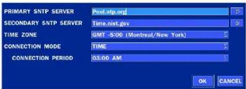
SYSTEM DESCRIPTION LANGUAGE DATE DISPLAY FORMAT DATE & TIME SETUP CLIENT ACCESS NTP SETUP SEND EMAIL SETUP UNIT NAME SYSTEM RESTART SYSTEM SHUTDOWN EZ SETUP SYSTEM EVENT NOTIFICATION ENGLISH MM/DD/YYYY ON DN OFF NVR 3 4 5 6 7 8 9 10 11 12 13 14 15 16 17 18 19 20 21 22 23 24 25 26 27 28 29 30 31 32 33 34 35 36 37 38 39 40 41 42 43 44 45 46 47 48 49 50 51 52 53 54 55 56 57 58 59 60 61 62 63 64 65 66 67 68 69 70 71 72 73 74 75 76 77 78 79 80 81 82 83 84 85 86 87 88 89 90 91 92 93 94 95 96 97 98 99 100- Select the proper TIME ZONE time.
text_image
PRIMARY SNTP SERVER Pool.ntp.org SECONDARY SNTP SERVER Time.nist.gov TIME ZONE GMT -5:00 (Montreal/New York) CONNECTION MODE TIME CONNECTION PERIOD 03:00 AM OK CANCELTable2.3.1. GMT Time Zone
| State | Standard Time | Daylight-Saving Time | |
| AL | Alabama | GMT-6 | GMT-5 |
| AK | Alaska | GMT-9 | GMT-8 |
| AK | Alaska (Aleutian Islands) | GMT-10 | NA |
| IL | Illinois | GMT-6 | GMT-5 |
| IN | Indiana | GMT-5 | GMT-4 |
| IN | Indiana (SW / NW) | GMT-6 | GMT-5 |
| IA | Iowa | GMT-6 | GMT-5 |
| KS | Kansas | GMT-6 | GMT-5 |
| KS | Kansas (W) | GMT-7 | GMT-6 |
| KY | Kentucky (E) | GMT-5 | GMT-4 |
| KY | Kentucky (W) | GMT-6 | GMT-5 |
| LA | Louisiana | GMT-6 | GMT-5 |
| ME | Maine | GMT-5 | GMT-4 |
| MD | Maryland | GMT-5 | GMT-4 |
| MA | Massachusetts | GMT-5 | GMT-4 |
| MI | Michigan | GMT-5 | GMT-4 |
| MI | Michigan (W) | GMT-6 | GMT-5 |
| MN | Minnesota | GMT-6 | GMT-5 |
| MS | Mississippi | GMT-6 | GMT-5 |
| MO | Missouri | GMT-6 | GMT-5 |
| MT | Montana | GMT-7 | GMT-6 |
| NE | Nebraska | GMT-6 | GMT-5 |
| NE | Nebraska (W) | GMT-7 | GMT-6 |
| NV | Nevada | GMT-8 | GMT-7 |
| NH | New Hampshire | GMT-5 | GMT-4 |
| NJ | New Jersey | GMT-5 | GMT-4 |
| NM | New Mexico | GMT-7 | GMT-6 |
| NY | New York | GMT-5 | GMT-4 |
| TX | Texas (W) | GMT-7 | GMT-6 |
| UT | Utah | GMT-7 | GMT-6 |
| VT | Vermont | GMT-5 | GMT-4 |
| VA | Virginia | GMT-5 | GMT-4 |
| WA | Washington | GMT-8 | GMT-7 |
| WV | West Virginia | GMT-5 | GMT-4 |
| WI | Wisconsin | GMT-6 | GMT-5 |
| WY | Wyoming | GMT-7 | GMT-6 |

NOTE: If you want the unit to automatically synchronize the local time, the Time Zone must be properly set according to your local time zone.
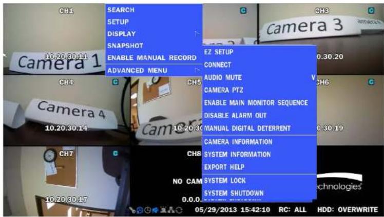
2-4. EZ SETUP
Quick Menu for ZS and IP Camera Easy installation(Right-Click on the Main Screen)
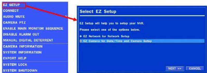
text_image
EZ SETUP CONNECT AUDIO MUTE CAMERA PTZ ENABLE MAIN MONITOR SEQUENCE DISABLE ALARM OUT MANUAL DIGITAL DETERRENT CAMERA INFORMATION SYSTEM INFORMATION EXPORT HELP SYSTEM LOCK SYSTEM SHUTDOWN Select EZ Setup EZ Setup will help you to setup your NVR. Please select one of the options below. ● EZ Network for Network Setup ○ EZ Camera for Date/Time and Camera Setup NEXT >> CANCELFigure 2.4. EZ Setup Screen
2.4.1. Setup DATE & TIME, IP CAMERA configurations.
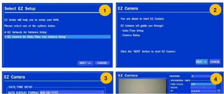
text_image
Select EZ Setup EZ Setup will help you to setup your NVR. Please select one of the options below. ● EZ Network for Network Setup D EZ Camera for Data/Time and Camera Setup NEXT >> CANCEL EZ Camera You are about to start EZ Camera EZ Camera will guide you through: - Data/Time Setup - Camera Setup Click the 'NEXT' button to start EZ Camera NEXT >> CANCEL EZ Camera DATE/TIME SETUP DATE DISPLAY FORMAT MM/DD/YYYY CHANNEL UPCAMERA INFO PROTOCOL ZIP SCAN IP 0.0.0.00 EZ Camera 42.4.2.EZ NETWORK (Using an internet connection)
text_image
EZ NETWORK Internet Connection Is your DVB connected to the internet? Yes (I will use an Internet connection) No (I will not use an Internet connection) NEXT >> CANCEL
text_image
EZ NETWORK LAN Setup Auto Configurden (DHCP) ✓ Get IP, Gateway, Safari Mask ✓ Search DNS Server ✓ Check Internet connectivity ✓ Search UPnP/PortForwarding Support UPnP Your network has been configured successfully! Please press "NEXT" to configure... << PREV Next >> CANCEL
text_image
EZ NETWORK LAN Setup Manual Configuration (STADIO) Test IP Address 172.16.2.38 15 Subset Mask 285.205.0.0 15 Gateway 172.16.1.254 15 DNS (Primary) 168.126.93.1 15 DNS (Secondary) 168.126.93.2 15 ✓ Check Internet connectivity ✓ Search UPnP/PurForwarding : Support UPnP Your network has been configured successfully! Please press "NEXT" to continue... < PREV NEXT > CANCEL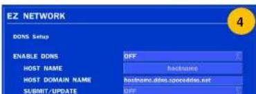
text_image
EZ NETWORK DONS Setup ENABLE DONS OFF HOST NAME hastname HOST DOMAIN NAME hastname.dites.spooodies.net SUBMIT/UPDATE OFF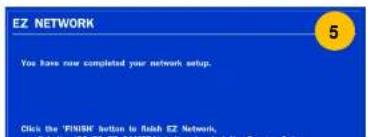
text_image
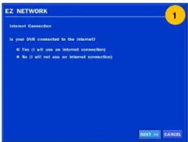
EZ NETWORK You have now completed your network setup. Click the 'FINISH' button to Rakeh EZ Network.2.4.3.EZ NETWORK setting (Not using internet connection)

text_image
EZ NETWORK Internet Connection Is your DVR connected to the Internet? • Yes (if will use an Internet connection) • No (if will not use an Internet connection) NEXT >> CANCEL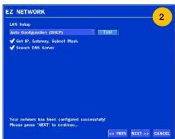
text_image
EZ NETWORK LAN Setup Auto Configuration (DHCP) Test ✓ Get IP, Gateway, Subnet Mask ✓ Search DNS Server Your network has been configured successfully! Please press 'NEXT' to continue... << PREV Next >> Cancel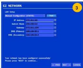
text_image
EZ NETWORK LAN Setup Manual Configuration (STATIC) Test IP Address 172.16.42 Satrot Mask 258.296.0.0 Gateway 172.16.254 DNS (Primary) 168.136.83.1 DNS (Secondary) 168.136.83.2 Your network has been configured successfully! Please press "NEXT" to continue... OK PREX NEXT OK CANCEL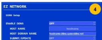
text_image
EZ NETWORK DONS Setup ENABLE DONS HOST NAME HOST DOMAIN NAME SUBMIT/UPDATE OFF localhost:ddns.speeddms.net OFF
text_image
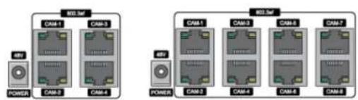
EZ NETWORK You have now completed your network setup. Click the YINESH button to finish EZ network. 52-5. PoE Port SETUP
text_image
IBD.5M RAM-1 RAM-3 IBP POWER RAM-2 RAM-4 IBP POWER IBD.5M RAM-1 RAM-3 RAM-5 RAM-7 RAM-2 RAM-4 RAM-6 RAM-8Figure 2.5. PoE Port (N4ZS/N8ZS)
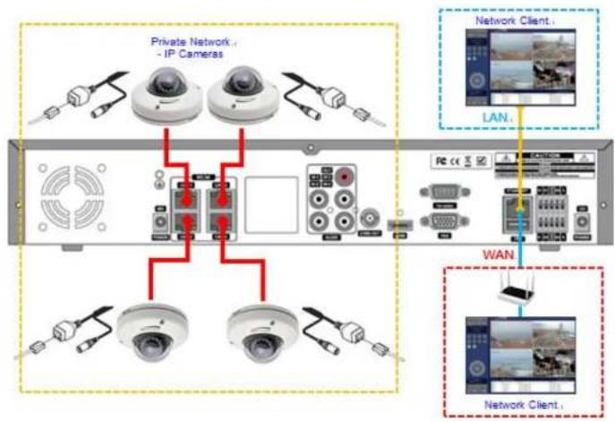
2.5.1 Connecting the Camera
flowchart
graph TD
    A["Private Network IP Cameras"] --> B["Camera Module 1"]
    A --> C["Camera Module 2"]
    A --> D["Camera Module 3"]
    A --> E["Camera Module 4"]
    A --> F["Camera Module 5"]
    G["Network Client"] --> H["Camera Module 1"]
    G --> I["Camera Module 2"]
    G --> J["Camera Module 3"]
    G --> K["Camera Module 4"]
    L["LAN"] --> M["Camera Module 1"]
    L --> N["Camera Module 2"]
    O["WAN"] --> P["Camera Module 1"]
    O --> Q["Camera Module 2"]
    R["Network Client"] --> S["Camera Module 1"]
    R --> T["Camera Module 2"]
    U["Network Client"] --> V["Camera Module 1"]
• The ZS Series features a "Plug and Play" function with a PoE Switch.
- The "Plug and Play" functionality requires the IP Camera to be in DHCP mode.
• The ZS automatically assigns an IP Address to the IP Camera. (192.168.78.11 \~ 254)
- The ZS models will automatically map the camera on the PoE Port to the corresponding ZS channel number.
flowchart
graph LR
    A["Router"] --> B["Switch"]
    B --> C["Network Device"]
    C --> D["Internal Component"]
    style C stroke:#ff0000,stroke-width:2px
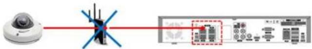
Figure 2.5.2. Incorrect connection with the PoE Ports
With the ZS Models, it is prohibited to connect a router to the POE Ports to connect the IP Camera, the ZS will not be able to find and connect to the camera. The LAN Port can be connected to a router, but not the PoE Ports.
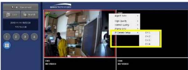
2-6. IP Camera SETUP (through SpecoTech Web Viewer)
ZS Series allows remote access to the IP Cameras through "IP Camera Setup" menu in SpecoTech Web Viewer.
text_image
2015.11.16 19:52:38 177-19:38 ENDC TECHNOLOGIES Export Tools High Quality Normal Quality Sharing Tools ST Camera Setup EN1.1 EN4.2 EN4.3 EN4.4 EN1.4 CMS NO VIDEO CMS NO VIDEO2-7. Dual Streaming
• High Quality (Main Profile) Video Stream is used for both Recording and Live Display.
- High Quality (Main Profile) Video Stream can be viewed through the network, when selected.
• Normal (Secondary) Quality Video Stream is used by default when viewing through the network.

flowchart
graph TD
    A["IP Camera"] -->|Live Display.| B["Monitoring"]
    B --> C["Recording"]
    C --> D["Network Clients"]
    D --> E["High/Normal Selection"]
    E --> F["Network Clients"]
    style A fill:#f9f,stroke:#333
    style B fill:#ccf,stroke:#333
    style C fill:#cfc,stroke:#333
    style D fill:#fcc,stroke:#333
    style E fill:#cff,stroke:#333
    style F fill:#ffc,stroke:#333
3. Front and Rear Panels
3-1. Desktop Front Panel

text_image
speco technologier ZS USB F2000 H20Figure 3.1.1. Desktop ZS Front panel
Table 3.1.1. Front LED and Port of ZS
| Name | Description |
| POWER | LED light is on when power is applied to the system. |
| HDD | LED light is on when the system is recording video data. |
| USB Port | This USB port is for archiving footage into a USB device. (USB 2.0) |
3-2. Connectors

- Do not power this system on before all the connections are completed.
- Make sure all the connections are properly secured. Faulty connection may result in the system being damaged.

text_image
1 2 3 4 5 6 7 N4ZS 8 9 10 11⑦ VGA OUT: Connector for VGA Monitor, Main Video Output.
⑧ RS232C: Console Interface
⑨ USB PORT: Connector for USB Mouse or USB flash memory.
⑩ ETHERNET PORT1: RJ-45 Connector for LAN Connection, used for Internet Connection
⑪ SENSOR IN, ALARM OUT, RS-485: 4 sensor inputs, 1 alarm output and RS-485 for PTZ
⑫ POWER: DC12V input
3-3. Remote Control

text_image
1 2 3 4 5 6 7 8 9 10 11 12 13 14 15 16 17 18 19 20 21 22 23 24 25 26 27 28 29 30 31 32 33 34 35 36 37 38 39 40 41 42 43 44 45 46 47 48 49 50① ID: Used to set up the remote control ID.
② REC: To enable or disable manual recording mode.
③ SEARCH: Goes to SEARCH menu for playback options.
④ F/ADV:
- During Playback – Moves the playback forward by 60 seconds.
- During Pause – Moves the playback forward by 1 frame.
⑤ F/REW:
- During playback – Moves the playback backward by 60 seconds.
4. Setting up the ZS
The following sections detail the initial setup of the ZS.

Menu screen will close if user input is not received within 5 minutes.
4-0. Setup - Main Live Screen
To enter the setup menu, right click on the mouse and select setup from the Quick Menu or press the setup button on the remote control.
text_image
CH1 10.20.30.11 CAMERA 1 SEARCH SETUP DISPLAY SNAPSHOT ENABLE MANUAL RECORD ADVANCED MENU CH4 10.20.30.14 CAMERA 4 CH5 10.20.30.17 CH8 NO CAM 0.0.0 EZ SETUP CONNECT AUDIO MUTE CAMERA PTZ ENABLE MAIN MONITOR SEQUENCE DISABLE ALARM OUT MANUAL DIGITAL DETERRENT CAMERA INFORMATION SYSTEM INFORMATION EXPORT HELP SYSTEM LOCK SYSTEM SHUTDOWN 05/29/2013 15:42:10 RC: ALL HDD: OVERWRITETable 4.0.1. Live Screen and Quick Menu
4-1. Setup - IP CAMERA
Press the SETUP button and enter the password. The IP Camera setup menu is displayed below.

text_image
IP CAMERA CHANNEL 1 PROTOCOL ZIP SCAN 0.0.0.0 IP 0.0.0.0 PORT 554 WEB PORT 80 ID admin PASSWORD **** SETUP APPLY CANCELFigure 4.1.1. IP Camera mode setup screen
Table 4.1.1. Menu items in IP CAMERA mode setup
Item
Description
CHANNEL
To manually connect each camera, click on the to get this window:
| PROTOCOL | SCAN | IP | PORT | WEB PORT | OTHERS | |
| 1 | ZIP | 0.0.0.0 | 554 | 80 |
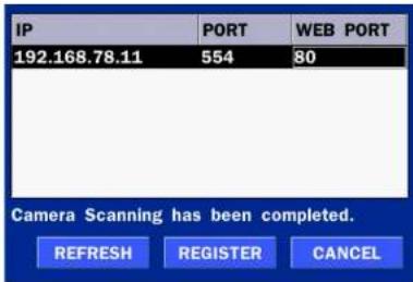
text_image
IP PORT WEB PORT 192.168.78.11 554 80 Camera Scanning has been completed. REFRESH REGISTER CANCELIP: Enter the address of IP camera to connect, or select from scanned list.
PORT: Enter the port number of IP camera to connect
WEB PORT: Enter the web port number of IP camera to connect
OTHERS: Change the IP camera setting. Double click the empty box and then Log-In box will be pop-up. (Enter ID and PASSWORD of IP Camera)

text_image
ID admin PASSWORD **** OKPROTOCOL Select the Brand of the Camera.
SCAN Automatic IP Camera Search the network. for IP Camera
IP Enter the IP Address of the desired Camera.
PORT Enter the Camera stream Port Number (default: 554)
WEB PORT Enter the Camera Web Port Number (default: 80)
ID Enter the User ID for access to the IP Camera
4-1-1. SCAN Menu
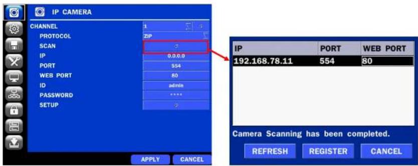
text_image
IP CAMERA CHANNEL 1 ZIP PROTOCOL SCAN IP 0.0.0.0 PORT 554 WEB PORT 80 ID admin PASSWORD **** SETUP APPLY CANCEL IP PORT WEB PORT 192.168.78.11 554 80 Camera Scanning has been completed. REFRESH REGISTER CANCELFigure 4.1.2 IP CAMERA Setup Screen
Figure 4.1.3 Search IP Camera Screen
① Select the specific manufacturer of IP Camera and then on click the scan button
② Select the camera on the list and then click the register button.
③ After the registration is completed, the basic information is to be displayed.
4-2. Setup - SYSTEM
In the SETUP menu, select the SYSTEM tab. Then, the SYSTEM menu is displayed as pictured below.
Navigate through the menu items or change the settings using the mouse or the remote control.
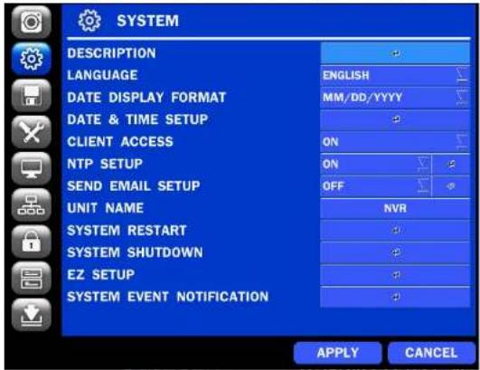
text_image
SYSTEM DESCRIPTION LANGUAGE DATE DISPLAY FORMAT DATE & TIME SETUP CLIENT ACCESS NTP SETUP SEND EMAIL SETUP UNIT NAME SYSTEM RESTART SYSTEM SHUTDOWN EZ SETUP SYSTEM EVENT NOTIFICATION ENGLISH MM/DD/YYYY ON ON OFF NVR APPLY CANCELFigure 4.2.1. SYSTEM Setup Screen
Table 4.2.1. Menu Items in SYSTEM Setup Screen
Item
Description
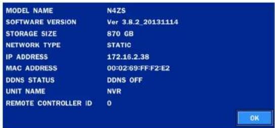
DESCRIPTION
Press the button to view the system information. (Software Version, Storage Size, IP Address, MAC Address and DDNS Status)
| MODEL NAME | N4ZS |
| SOFTWARE VERSION | Ver 3.8.2.20131114 |
| STORAGE SIZE | 870 GB |
Select DAYLIGHT SAVINGS using the mouse or the remote control and select the appropriate daylight savings time zone. The options are:
OFF: Daylight saving is turned off.
USA: Applies the USA daylight saving time.
EU: Applies the EU daylight saving time.
- Select the GMT AREA using the mouse or the remote control.
- Set the time difference with the standard time using the mouse or the button.
OTHERS: If the time zone is neither USA nor EU, set the date and time of the daylight saving period.
Select BEGIN or END.
Caution
- Do not set the start time to 23:00 for DLS.
- DLS cannot be applied if the date of BEGIN and END is the same.
CLIENT
Enable/Disable remote access through the network.
ACCESS
NTP
SETUP
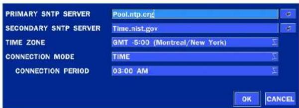
NTP (Network Time Protocol) which synchronizes the time of the computer systems over variable-latency data networks.
text_image
PRIMARY SNTP SERVER Pool.ntp.org SECONDARY SNTP SERVER Time.nist.gov TIME ZONE GMT -5:00 (Montreal/New York) CONNECTION MODE TIME CONNECTION PERIOD 03:00 AM OK CANCELPRIMARY SNTP SERVER: Input the address of the primary NTP time-server
SYSTEM TIME: Mon Oct 10 13:46:49 2011
SERVER TIME: Mon Oct 10 13:33:12 2011
ZS ID: ZS
IP ADDRESS: 172.16.2.46"
SEND EMAIL
text_image
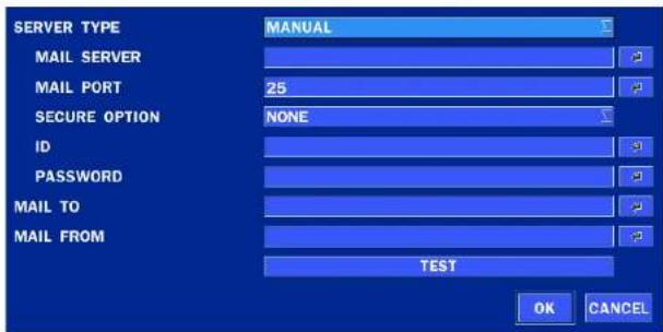
SERVER TYPE MAIL SERVER MAIL PORT SECURE OPTION NONE ID PASSWORD MAIL TO MAIL FROM TEST OK CANCELSERVER TYPE: Select GMAIL, HOTMAIL, AOL, YAHOO or MANUAL)
MAIL SERVER: Enter the appropriate mail server information.
MAIL PORT: Assign Mail Port number.
SECURE OPTION: Select the secure mail server connection method. (SSL or TLS)
ID: Enter the appropriate mail server ID.
PASSWORD: Enter the appropriate mail server PASSWORD
MAIL TO: Enter the appropriate email address to enable sending e-mail reports using a virtual keyboard.
MAIL FROM: To set the email address sent to the destination host.
TEST : E-mail settings sent a test mail to the registered account
UNIT NAME
Name the 7S (e.g. Factory)
HEALTH CHECK - OFF, ON
(Allows the user to set MAIL STATUS periodically) : DAILY or WEELY or MONTHLY

text_image
PERIOD DAILY FIRST SUN 0 H OK CANCELEVENT AND NOTIFICATION - OFF, ON
(Allows the user to set EVENT NOFICIATION ON or OFF)
HEALTH CHECK / RESTART / SHUTDOWN / PANIC RECORD
- Enable Email Notification in the event a problem occurs with the ZS.
4-3. Setup - RECORD Mode
In the SETUP menu, select the RECORD tab. Then, the RECORD menu is displayed as pictured below.
Navigate through the menu items or change the settings using the mouse or the remote control.

text_image
RECORD SITE CH 1 RECORDING MODE CONTINUOUS SENSOR RECORDING PRE RECORD 1 MINUTE(S) POST EVENT RECORD 10 SECOND(S) AUDIO OFF SCHEDULE APPLY CANCELFigure 4.3.1. RECORD Setup Screen
Table 4.3.1. Menu Items in RECORD Setup Screen
| Menu Item | Description |
| SITE | Select a channel for applying the following settings using the mouse or the remote control. To change the values of all channels, take the following steps. Select the button to change the values of all channels. |
AUDIO
Enable/disable audio recording for the specified channel.
SCHEDULE
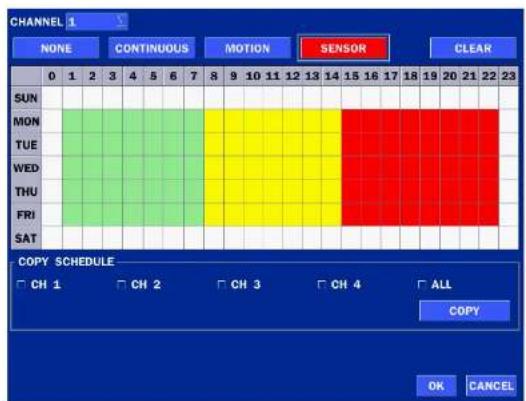
To setup a recording schedule, select SCHEDULE in the RECORD menu. Navigate through the menu items or change the settings using the mouse or the remote control.
Select CHANNEL > select NONE, CONTINUOUS, MOTION or SENSOR > Highlight area
To copy a schedule to a different channel, select the channel from the COPY SCHEDULE menu.
text_image
CHANNEL 1 NONE CONTINUOUS MOTION SENSOR CLEAR 0 1 2 3 4 5 6 7 8 9 10 11 12 13 14 15 16 17 18 19 20 21 22 23 SUN MON TUE WED THU FRI SAT COPY SCHEDULE CH 1 CH 2 CH 3 CH 4 ALL COPY OK CANCELFigure 4.3.2. Schedule Recording Setup Screen
- NONE: Disable recording during selected timeframe (Highlighted in White)
• CONTINUOUS: CONTINUOUS recording (Highlighted in Green)
• MOTION: MOTION recording (Highlighted in Yellow)
4-4. Setup - DEVICE Mode
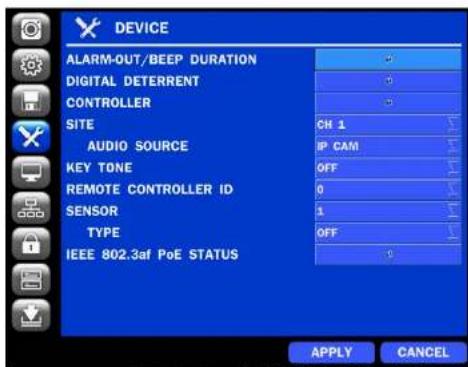
In the SETUP menu, select the DEVICE tab. Then, the device menu is displayed as pictured below. Navigate through the menu items or change the settings using the mouse or the remote control.
text_image
DEVICE ALARM-OUT/BEEP DURATION DIGITAL DETERRENT CONTROLLER SITE AUDIO SOURCE KEY TONE REMOTE CONTROLLER ID SENSOR TYPE IEEE 802.3af PoE STATUS CH 1 IP CAM OFF 0 1 OFF 0 APPLY CANCELFigure 4.4.1. DEVICE Setup Screen
Table 4.4.1. Menu Items in DEVICE Setup Screen
| Item | Description |
| ALARM OUT | Only one Alarm-out is available. |
| / BEEP DURATION | Set alarm dwell time from 5 to 60 seconds or infinite. |
 | |
| The options are from 0 to 99 | |
| SENSOR | Select the type of each sensor.Option is Off, Normal Open or Normal Close. |
| IEE 802.3af POE STATUS | POE (Power Of Ethernet) Status Monitoring Menu |
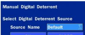
4-4-1. Digital Deterrent
Trigger audio message via motion detection or sensor.

text_image
IMPORT FROM USB ... EXPORT TO USB ... RECORD ... SCHEDULE ... OKFigure 4.4.2. Digital Deterrent setup screen
Table 4.4.2. Item for Digital Deterrent Setup Screen
| Item | Description |
| IMPORT FROM USB | Import up to 8 sound files from USB. |
| EXPORT TO USB | Export the sound file to USB |
| RECORD | Select a channel and set up the date and the duration.And, select the sound file to play. |
 |
4-5. Setup - DISPLAY Mode
In the SETUP menu, select the DISPLAY tab. Then, the DISPLAY menu is displayed as pictured below. Navigate through the menu items or change the settings using the mouse or the remote control. To return to the previous setup menu screen, press the ESC button.
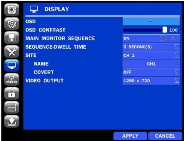
text_image
DISPLAY OSD OSD CONTRAST MAIN MONITOR SEQUENCE SEQUENCE-DWELL TIME SITE NAME COVERT VIDEO OUTPUT 100 ON 3 SECOND(S) CH 1 CH1 OFF 1280 x 720 APPLY CANCELFigure 4.5.1. DISPLAY Setup Screen
Table 4.5.1. Menu Items in DISPLAY Setup Screen
| Item | Description |
| OSD | Enable/Disable on-screen-display. |
| SEQUENCE | Set the dwell time of each, |
| DWELL TIME | single channel display in sequential display mode (3~60 seconds) |
| SITE | Select a channel to apply the name and covert settings change using the mouse or the remote control.Select a channel to apply the following settings using the mouse. |
| NAME | Set the channel name. Press the right square button and set the channel name and select OK using the mouse.The name can be made up to 10 characters. |
| COVERT | Enable/disable display of the specified video channel in live display. |
| VIDEO OUTPUT | Select 1280x720 or 1920x1080. |
4-6. Setup - NETWORK Mode
Select the NETWORK tab. Then, the network menu is displayed as pictured below. Navigate through the menu items or change the settings using the mouse or the remote control.

text_image
NETWORK NETWORK TYPE IP 172.16.2.38 SUBNET MASK 255.255.0.0 GATEWAY 172.16.1.254 DNS (PRIMARY) 168.126.63.1 DNS (SECONDARY) 168.126.63.2 DDNS 5445 NETWORK PORT NETWORK AUDIO PORT 5446 WEB PORT 80 WIRELESS LAN OFF| constantly synchronized with a dynamic IP address. In other words, it allows using a dynamic IP address to be associated with a static domain name so others can connect to it by the static name.Enable/disable using domain name address through DDNS server. | |
| NETWORK PORT | Enter the port number. |
| NETWORK AUDIO PORT | Display the network audio port (NETWORK PORT + 1). |
| WEB PORT | Enter the port number for connection using web. |
| WIRELESS LAN | Wireless networks can be configured(option) |
4-6-1. Network Types
4-6-1-1. DHCP
DHCP server automatically assigns the IP address and other parameters to new devices.
4-6-1-2. STATIC
IP address, Subnet Mask, Gateway, and DNS are manually assigned by the user.
• IP ADDRESS: The fixed IP address of the ZS unit.
- SUBNET MASK: The subnet mask for the LAN.
• GATEWAY: The IP address of the Gateway.
• DNS (PRIMARY) The primary address of Domain Name Server
• DNS (SECINDARY): The secondary address of Domain Name Server

NOTE
Unless DNS is properly set, the DDNS and the e-mail features will not work.
4-6-2 DDNS
Table 4.6.2. DDNS
| Item | Description |
| ENABLE DDNS | Turn DDNS on/off |
| HOST NAME | This item allows the user to setup a domain name manually using virtual keyboard displays as shown. |
| SUBMIT/UPDATE | When manual host name input is done, move the cursor to this item and select ON to submit the settings. |
| ezDDNS | Enable/disable ezDDNS to register the host name automatically. |
4-6-3. Network Port and Web Port
Connecting ZS through a common IP sharing device, each ZS must be assigned a unique TCP port number for access from outside the LAN. This port number is displayed on NETWORK>NETWORK PORT Setup MENU.

NOTE:
If you access the ZS only within the same LAN, the TCP port number does not need to be changed.
Network access beyond a router
To access ZS beyond a router (firewall), you must open the proper TCP ports for live/playback streaming, for commands, for remote backup, and for audio streaming. If these ports are not opened properly, you can't access the ZS beyond a router.

For live/playback streaming, for commands, for remote backup: Open the port number on NETWORK>NETWORK PORT menu. The default port number is 5445.
For bi-directional audio: Open the port number on NETWORK AUDIO PORT. The default port number is NETWORK PORT number + 11
4-7. Setup - USER MANAGEMENT Mode
In the SETUP menu, select the USER MANAGEMENT tab. Then, the USER MANAGEMENT menu is displayed as pictured below. Navigate through the menu items or change the settings using the mouse or the remote control.

text_image
USER MANAGEMENT AUTHORITY SETUP USER NAME SETUP PASSWORD SETUP PLAYBACK AUTHORITY APPLY CANCELFigure 4.7.1. USER MANAGEMENT Setup Screen
Table 4.7.1. Menu Items in USER MANAGEMENT Setup Screen
| Item | Description | |||
| AUTHORITY | Only the Admin will have access to the menu. | |||
| SETUP | PASSWORD CHECK: Select the Checkbox to enable the functions or leave the Checkbox blank to disable the functions. | |||
| ADMIN, USER1, USER2, USER3:Selected Checkbox: The user can access the function.Blank Checkbox: The user can not access the function. | ||||
| USER NAMESETUP | Change the name of USER1, USER2 and USER3.● Click "ENTER" after naming. | |||
PASSWORDSETUP | Passwords can be changed for ADMIN, USER1, USER2 and USER3.Select USER PASSWORD using the mouse or the remote control. Select username and enter the current password. And, enter a new password, enter the same password again to confirm and select OK. Then the message "PASSWORD CHANGED" is displayed.The factory default password is 1111.It is highly recommended to assign a new password to protect the system. | |||
| PLAYBACKAUTHORITY | Set authority level of playback on each user.Checked box: authorized to playback. Blank check box: no authority. | |||
| 1 | 2 | 3 | ||
| ADMIN | ☑ | ☑ | ☑ | |
| USER1 | ☑ | ☑ | ☑ | |
| USER2 | ☑ | ☑ | ☑ | |
| USER3 | ☑ | ☑ | ☑ | |
| 1 | 2 | 3 | 4 | |
| ADMIN | ☑ | ☑ | ☑ | ☑ |
| USER1 | ☑ | ☑ | ☑ | ☑ |
| USER2 | ☑ | ☑ | ☑ | ☑ |
| USER3 | ☑ | ☑ | ☑ | ☑ |
4-8. Setup - STORAGE Mode
In the SETUP menu, select the STORAGE tab. Then, the STORAGE menu is displayed as pictured below. Navigate through the menu items or change the settings using the mouse or the remote control.
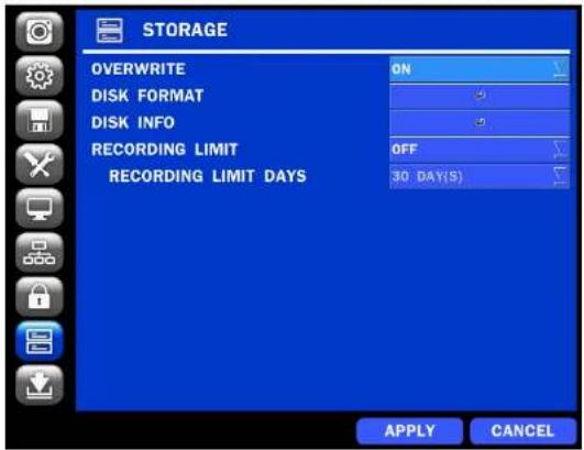
text_image
STORAGE OVERWRITE ON DISK FORMAT 5 DISK INFO 5 RECORDING LIMIT OFF 30 DAY(S) RECORDING LIMIT DAYS APPLY CANCELFigure 4.8.1. STORAGE Setup Screen
Table 4.8.1. Menu Items in STORAGE Setup Screen
| Item | Description |
| OVERWRITE | When enabled, the ZS will continue recording and overwrite the oldest existing recorded data once the hard drive is full. When disabled, recording will stop once the hard drive is full. |
| DISK FORMAT | Once clicked, the user will have to confirm to format the Hard Drive.After confirming, the ZS will reboot, and the format sequence will load. |
| Reallocated Sectors | Current Pending Sectors | Uncorrectable Sectors | Spin Retry Count | |
| HDD 1 | 0 | 0 | 0 | 0 |
| HDD 2 | ||||
| HDD 3 | ||||
| HDD 4 | ||||
| HDD 5 | ||||
| HDD 6 |
RECORDING LIMIT
Enable recording limit: The amount of data recorded in HDD will be limited to the most recent number of days as set by "RECORDING LIMIT DAYS".
Disable recording limit : When OVERWRITE is ON, DVR will continue to record when HDD is full and overwrite older data. When OVERWRITE is OFF, DVR will stop recording when the HDD is full.
Set the recording limit days. (1- 90 days)
If the RECORDING LIMIT DAYS are set to 1, the data will be overwritten after 24 hours.
4-9. Setup - CONFIG Mode
In the SETUP menu, select the CONFIG tab. Then, the configuration menu is displayed as pictured below. Navigate through the menu items or change the settings using the mouse or the remote control.

text_image
CONFIG EXPORT TO USB IMPORT FROM USB LOAD DEFAULT LOAD FACTORY DEFAULT SOFTWARE UPGRADE APPLY CANCELFigure 4.9.1. CONFIGURATION Setup Screen
Table 4.9.1. CONFIGURATION Setup
SOFTWARE
Upgrade software to the latest version.
UPGRADE
After connecting USB flash drive to USB port on the ZS, click SEARCH.
It will automatically find the upgrade file.
4-9-1. Firmware Upgrade
- Create a new folder named "upgrade" in the USB flash drive root directory.
- Create sub-folder for each model under "upgrade" folder and copy each firmware.
- "n4zs" for N4ZS: "main_n4ns_speco_.*.*_201****"
- "n8zs" for N8ZS: "main_n8ns_speco_.*.*_201****"

text_image
Computer > Removable Disk (C) > Upgrade > File Edit View Insert Modify Remove M25 M25 Data modified Type 3/20/214 10:30 AM File Color 3/20/214 10:30 AM File Color Data modified S:\30\214\10\30\AM M25 Data modified S:\30\214\10\30\AM
- Plug in the USB flash drive on the rear panel.
- Navigate to CONFIG menu of SETUP.
- Select SOFTWARE UPGRADE.
- Follow the procedure from Figure 4.9.2 to Figure 4.9.4.
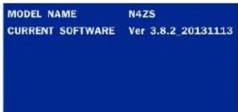
text_image
MODEL NAME N4ZS CURRENT SOFTWARE Ver 3.8.2 20131113
text_image
MODEL NAME N4ZS CURRENT SOFTWARE Ver 3.8.2_20131113 USB CHECK FOUND USB MOUNT OK FILE CHECK main_N4ZS_speco_3.8.2_20131113.bln
NOTICE
- If selecting REBOOT LATER, the upgraded software will not be applied until the system reboots.
- If selecting REBOOT NOW when the USB flash drive is plugged, the following message will pop up: Remove the USB flash drive and select OK.
5. Live, Search and Playback
5-1. Live View
In the Live screen, video inputs from the cameras are displayed as they are configured in the Display Setup screen. Various On-Screen Display (OSD) symbols, which indicate the status of the ZS, are described in Table 5.1.1.

text_image
CH1 10.20.30.13 CAMERA 1 CH4 10.20.30.14 CH7 10.20.30.17 SEARCH SETUP DISPLAY SNAPSHOT ENABLE MANUAL RECORD ADVANCED MENU CH5 10.20.30 EZ SETUP CONNECT AUDIO MUTE CAMERA PT2 ENABLE MAIN MONITOR SEQUENCE DISABLE ALARM OUT MANUAL DIGITAL DETERRENT CAMERA INFORMATION SYSTEM INFORMATION EXPORT HELP NO CAM SYSTEM LOCK SYSTEM SHUTDOWN 0.0.0 05/29/2013 15:42:10 RC: ALL HDD: OVERWRITE

05/29/2013 15:42:10
Indicates that a network client is connected to the ZS.
Indicates that sequencing mode is enabled.
RC: ALL
Displays the current date and time.
Remote control ID display. If a remote ID is not set, the message "ALL" is displayed.
HDD: OVERWRITE
Displays the amount of recording on the hard disk from 0-99%.

Indicates that HDD is recycled.

Continuous recording in progress.

Manual recording in progress. To set the Manual recording mode, press the Record button on the front panel.

Motion alarm recording in progress.

Sensor recording in progress.
Right click the mouse, and the Quick Menu will be displayed as below.
EZ SETUP
CONNECT
AUDIO MUTE
V
Table 5.1.2. Menu Items in Quick Menu
| Icon | Description |
| SEARCH | Search button. Click this button to enter the search menu. |
| SETUP | Select this option to enter the Setup menu. |
| DISPLAY | Select between different multi-view display formats. |
| SNAPSHOT | Capture pictures and store as BMP files |
| ENABLE MANUAL | Manual Record button. Click this button to enable manual recording. |
| RECORD |
ADVANCED MENU
| EZ SETUP | Select this option to start EZ Setup Wizard. |
| CONNECT | Select this option to disconnect/connect from IP Camera. |
| AUDIO MUTE | Select this option to mute audio on all channels. |
| CAMERA PTZ | Pop up the PTZ user interface. |
| ENABLE MAIN | Sequence button. Click this button to use a sequence function. |
| MONITOR | |
| SEQUENCE | |
| ON/OFF | |
| DISABLE | Click this button to enable/disable Alarm outputs |
| ALARM OUT | |
| MANUAL | Select this option to manually trigger any of the saved Digital Deterrent messages. |
| DIGITAL |
DETERRENT
text_image
MODEL NAME N4ZS SOFTWARE VERSION Ver 3.8.2_20131114 STORAGE SIZE 870 GB NETWORK TYPE STATIC IP ADDRESS 172.16.2.38 MAC ADDRESS 00:02:69:FF:F2:E2 DDNS STATUS DDNS OFF UNIT NAME NVR REMOTE CONTROLLER ID 0 OKEXPORT HELP
Displays window with instructions for exporting video.

text_image
SUB-MENU*SYSTEM
Locks the ZS from unauthorized user access.
LOCK
SYSTEM
Select this option to shutdown system.
SHUTDOWN
5-1-1. PTZ Control
Table 5.1.3. Menu Items in PTZ Control Window
| Item | Description |
| INITIALIZE | Initialize the PTZ settings of the selected camera |
| PAN/TILT | Select PAN/TILT using the ▲▼◀ and ▶button, then press SEL.Adjust the tilt (UP/DOWN) & pan (LEFT/RIGHT) position using the ▲▼◀and ▶buttons. |
| ZOOM/FOCUS | Select ZOOM/FOCUS using the ▲▼◀ and ▶buttons, then press SEL.Adjust the zoom (UP/DOWN)/ focus (LEFT/RIGHT) position using the ▲▼◀ and ▶ buttons. |
| OSD | Select OSD to enter the menu. Control keys are Right, Left, UP, Down, Select, Far (REW KEY), and Near (FF KEY).Press the ESC button to return to the previous menu. Press the PTZ button to close the OSD menu. |
| AUTOSCAN | Press the right key (▶) to start auto scan.Press the left key (◀) to stop auto scan. |
| PRESET | Select PRESET, and then press the left key (◀). A number input window will appear.Set the number (3 digits) using the number key, and then press the SEL to confirm the preset number for the current position. Press the right key (▶) and enter the number (3digits) to go to the preset position. |
| TOUR | Select TOUR and press the right (▶) key. A number input window will soon. |

text_image
PTZ CH 2 INITIALIZE PAN/TILT ZOOM/FOCUS SEL ESC OSD AUTOSCAN PRESET TOUR 1 2 3 No :5-2. Digital Zoom in Live and Playback Screen
ZS series supports Digital Zoom feature during live and playback mode.
- Double click the target channel.

text_image
CH 2 CH 5 CH 6- Click the left button of the mouse and drag to make rectangular shape.
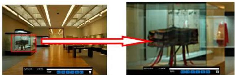
natural_image
Interior view of a modern exhibition hall with display cases and a red arrow pointing to a museum exhibit (no visible text or symbols)5-3. SEARCH Screen
To enter the search screen menu, select SEARCH menu on the screen using the mouse or press SEARCH icon on live screen.
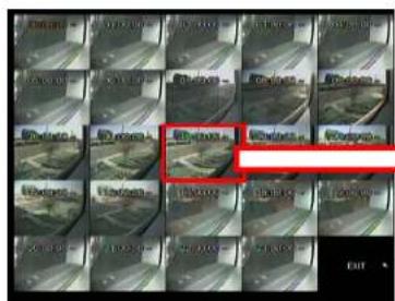
5-3-1. EZSearch
The EZSearch window is used to find stored video with ease using the thumb nail playback screen.

text_image
May, 2013 Sun Mon Tue Wed Thu Fri Sat 5 6 7 8 9 10 11 12 13 14 15 16 17 18 19 20 21 22 23 24 25 26 27 28 29 30 31 < PREV NEXT > CLOSEFigure 5.3.2. Calendar Screen

text_image
CH1 CH2 11/15/2013 CH1 0 3 4 8 12 18 21 24 ON CH1 2 CH1 4 CH1 6 CH1 8 CH1 10 CH1 12 CH1 14 CHANNEL 0 CH1 0 CH2 0 CH3 0 CH4 NO PREF PLAY CLOSE ON 0.0.0.0 0.0.0.0 VDD: 海通A 11/15/2013 13:27:30 RC: ALL HBD: OVERWRITEFigure 5.3.3. Channel Selection Screen
text_image
Grid of surveillance cameras with red annotation highlighting a specific camera's focus areaFigure 5.3.4. 24 Hourly Thumbnail Screen
text_image
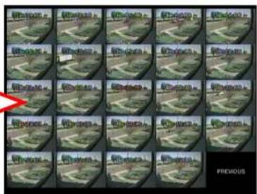
PREVIOUSFigure 5.3.5. Minute Thumbnail Screen

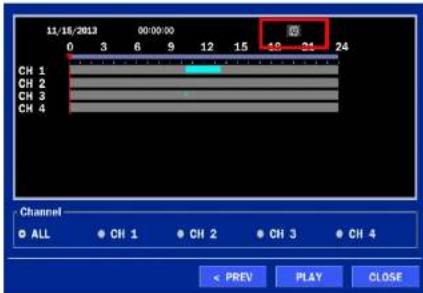
5-3-2. Time Line Search
The CALENDAR Search window is used to find the stored video by using the time line bar.

text_image
May, 2013 Sun Mon Tue Wed Thu Fri Sat 5 6 7 8 9 10 11 12 13 14 15 16 17 18 19 20 21 22 23 24 25 26 27 28 29 30 31 < PREV NEXT > CLOSEFigure 5.3.7. Calendar Screen
text_image
11/16/2013 00:00:00 CH 1 CH 2 CH 3 CH 4 Channel ● ALL ● CH 1 ● CH 2 ● CH 3 ● CH 4 < PREV PLAY CLOSEFigure 5.3.8. Time-Line Search Screen
When the Timeline menu is selected, the user can see a calendar, which displays recorded dates with highlights. Select a specific date and time. Click and drag the red time indicator bar to the desired hour. User can select specific minutes using a button in the above red box. Press the PLAY button after selecting the specific time. Press the PREV to return to the SEARCH window.
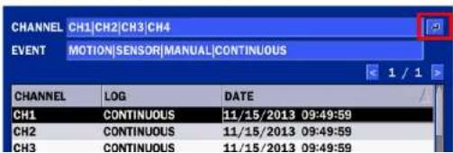
5-3-3. Event Search
The Event Search window is used to find stored video.
text_image
CHANNEL CH1|CH2|CH3|CH4 EVENT MOTION|SENSOR|MANUAL|CONTINUOUS CHANNEL LOG DATE CH1 CONTINUOUS 11/15/2013 09:49:59 CH2 CONTINUOUS 11/15/2013 09:49:59 CH3 CONTINUOUS 11/15/2013 09:49:59
text_image
Channel ALL CH1 CH2 CH3 CH4 Event ALL MOTION SENSOR MANUAL CONTINUOUS OK CANCELFigure 5.3.10. Event Search Screen
5-3-4. Go To First Time
User can access from the oldest recorded data on the ZS hard drive by selecting GO TO FIRST TIME on the SEARCH window. Press the PREV to return to the SEARCH window.
5-3-5. Go To Last Time
User can access from the last minute recorded data on the ZS hard drive by selecting GO TO LAST TME on the SEARCH window. Press the PREV to return to the SEARCH window.
5-3-6. Go To Specific Time
User can search for video data from a specific instance by setting the date and time in the GO TO SPECIFIC TIME menu. Use the mouse or the remote control to change the date and time value and press the PLAY button after setting. If there is no video data in the set date and time, No Data Exist message displays.
5-3-7. Archive List
The ARCHIVE Search window is used to find previously stored video or images.

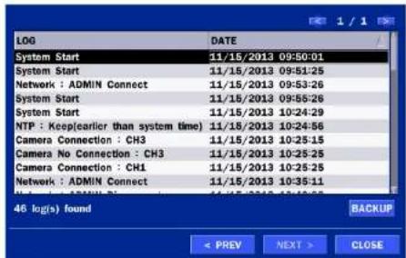
5-3-8. Log List
You can access the LOG list search screen by selecting LOG on the SEARCH window.
text_image
LOG DATE System Start 11/15/2013 09:50:01 System Start 11/15/2013 09:51:25 Network : ADMIN Connect 11/15/2013 09:53:26 System Start 11/15/2013 09:58:26 System Start 11/15/2013 10:24:29 NTP : Keep(earlier than system time) 11/15/2013 10:24:56 Camera Connection : CH3 11/15/2013 10:25:15 Camera No Connection : CH3 11/15/2013 10:25:25 Camera Connection : CH1 11/15/2013 10:25:25 Network : ADMIN Connect 11/15/2013 10:35:11 46 log(s) found BACKUP < PREV NEXT > CLOSEFigure 5.3.12. Log List Screen
When the Log menu is selected, the user can see a calendar, which has a log data. Select a specific date and press NEXT button, and then the log data will be displayed. Press the SAVE button to save the data and then the data is saved as a text file format.
5-4. Play Mode
During playback of a recorded event, the mode changes from SEARCH to PLAY. While in PLAY mode, user may return to the SEARCH screen by pressing the X button on the status bar.

text_image
CH2 NO DATATable 5.4.1. Button Functions in PLAY Mode
| Button | Description |
 | 2x, 4x, 8x,16x, 32x speeds at 2x2 screen display mode.2x, 4x, 8x,16x speeds at 3x3 screen display mode.2x, 4x, 8x speeds at the 4x4 screen display mode.Single Channel backward playback speed 1x, 2x, 4x, 8x, 16x, 32x, 64x |
 | Jump/Step backward. The playback position moves 60 seconds backward. |
 | Press to play or pause recorded video. |
 | Jump/Step forward. Playback position moves 60 seconds forward. |
 | 2x, 4x, 8x,16x, 32x speeds at 2x2 screen display mode2x, 4x, 8x,16x speeds at 3x3 screen display mode.2x, 4x, 8x speeds at the 4x4 screen display mode.Single Channel forward playback speed 1x, 2x, 4x, 8x, 16x, 32x, 64x |
 | Slow Mode play. Forward playback speed x1/4, x1/2 |
 | Press to Backup the video. |
 | EZCopy button. |
 | Return to the previous menu screen, search window, or exit from the Menu. |
6. Back Up
6-1. Video Backup onto USB Flash Drive during playback
Video can be captured and archived onto the USB flash drive or a hard drive while playing back the
recorded video. In playback mode, press the BACKUP button to launch the backup function.
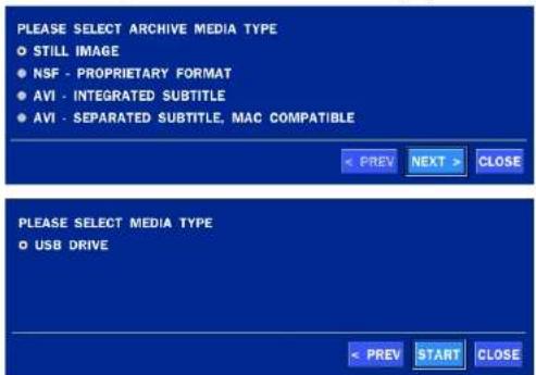
- When you press BACKUP button on the selected channel or all channels, the ZS will ask whether to archive a Still Image, a NSF or AVI and select the proper media type.
text_image
PLEASE SELECT ARCHIVE MEDIA TYPE ○ STILL IMAGE ● NSF - PROPRIETARY FORMAT ● AVI - INTEGRATED SUBTITLE ● AVI - SEPARATED SUBTITLE, MAC COMPATIBLE < PREV NEXT > CLOSE PLEASE SELECT MEDIA TYPE ○ USB DRIVE < PREV START CLOSE- Select USB STICK (Flash Drive) to back up less than an hour. Select USB HDD (Large Backup) to back up from 1 hour to 24 hours. (Only for NSF type)

- The following image shows the progress of archiving the data.

text_image
90% < PREV START CLOSE- The following shows the image to complete the backup. Select close to return to the previous screen.

text_image
100% COMPLETE + PREV START CLOSE6-2. EZCopy: Video Backup onto USB Flash Drive during playback
Using EZCopy feature, Video can be easily archived onto the USB flash drive or a hard drive.
In playback mode, press the

OPY button to launch the backup function.
- Press EZCOPY button on the selected channel or all channels.

text_image
- 1/4 + EZ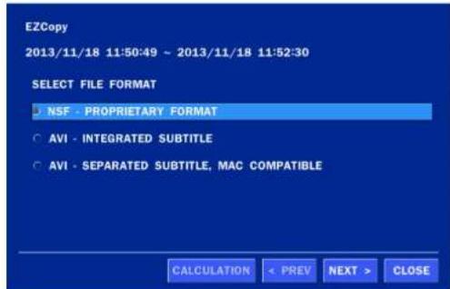
text_image
EZCopy 2013/11/18 11:50:49 ~ 2013/11/18 11:52:30 SELECT FILE FORMAT • NSF - PROPRIETARY FORMAT ○ AVI - INTEGRATED SUBTITLE ○ AVI - SEPARATED SUBTITLE, MAC COMPATIBLE CALCULATION < PREV NEXT > CLOSE- After backup format is selected, also select media type and channel(s) to archive the data to the media.
6-3. Transferring Still Images or Video from the ARCHIVE List
The stored data in the hard drive can be found in the ARCHIVE list in the SEARCH window. User can back up still images or video into the storage device from the ARCHIVE list.
- Select the date to begin searching and navigate through the days using the mouse or the remote control.
- Once you have selected the date, press the NEXT button to open the list of stored data.
- Use the mouse or the remote control to scroll through the archive list.
- Select a list of stored events in the archive list.
- Once the desired event has been selected, press the DISPLAY button to view the still image or the first frame of the selected video.
- Press the BACKUP button to launch the archiving function in playback mode.
- Press the CLOSE button to return to the SEARCH window.
6-4. Playback of Backup Video
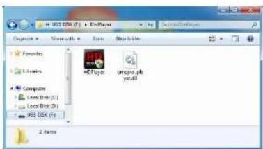
6-5-1. AVI Format
AVI format: AVI format video can be played back by Window Media Player™ or other media player that is compatible with AVI format video.
- Please install the ZS copies "HDPlayer" folder on USB flash drive with the video.
text_image
US1206 (F) - FoxPlayer SapiRv400000 Options > Save all > Run > New Index Favorites Libraries Computer Last Disk(D) Last Disk(D) US1206 (F) HP503 uniproc.p5 2 days- Otherwise, the video and time stamp over video can't be properly played back and displayed on Window Media Player™.
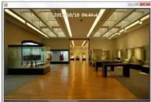
natural_image
Interior view of a museum or exhibition hall with wooden flooring, display cases, and ceiling lighting (no visible text or signage)
Timestamp On AVI. The subtitle is embedded to the video clip file.
ubtitle is embedded to the AVI file.
7. Network Access Using the Multi-Sites Network Viewer
7-1. Overview
The SpecoTech Multi Client is a multiple site monitoring client software with; video, audio, and alarm signals from the ZS over the network. The SpecoTech Multi Client does not limit the number of ZS units to register. The program displays up to 16 ZS units and supports dual monitors.
On the program, user may control PTZ cameras on the ZS. By attaching a microphone and speaker system to devices on site, the user may make bi-directional audio communication over the network.
7-2. PC Requirements
Minimum PC Requirements
| CPU | Intel Core i3 |
| 1.8Ghz | |
| Memory | 2GB DDR2 |
| VGA | 512MB |
| Resoluon | 1280x720 |
| Disk Space | 1GB |
| OS | Windows 2000, XP Professional, XP Home, Vista, 7 (NOTE: Not all versions of Vista and 7 are supported) |
| Network | 10/100Base T |
| Others | Direct X 9.0c or Higher |
Recommended PC Requirements
| CPU | Intel Core i5 |
| 2Ghz or higher. |
7-3. Installation of the Program
- Insert the provided CD in the CD drive and double-click "SpecoTech Multi Client (XXXX).exe"
- Select a destination folder and click "Next".

text_image
InstallShield Wizard Choose Destination Location Select folder where Setup will install files. Setup will install SpecoTech Multi Client in the following folder. To install to this folder, click Next. To install to a different folder, click Browse and select another folder. Destination Folder C:\Speco Technologies\SpecoTech Multi Client Browse... < Back Next > Cancel- Select the program folder and click "Next".
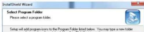
text_image
InstallShield Wizard Select Program Folder Please select a program folder. Setup will add program icons to the Program Folder listed below. You may type a new folder7-4. Live Window
When installation is completed, double click the "SpecoTech Multi Client" icon on your desktop to start the program.
7-4-1. Main User Interface
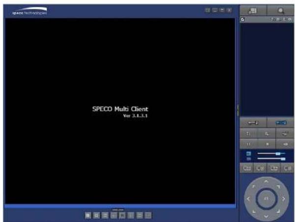
text_image
SPECO Multi Client Ver 3.1.3.17-4-2. Control Buttons
 |
 | SETUP | Click this icon to setup configuration of SpecoTech Multi Client. |
 | CAPTURE | Click this icon to capture a still image. |
 | EVENT LIST | Opens list of events logged by the SpecoTech Multi Client. |
 | PAUSE | Click this icon to play/pause live video. |
 | ALARM ON | Click this icon to turn on/off alarm outputs. |
 | RECORD ON | Enable or disable recording of live video to local disk, which has set in setup menu. |
 | Use the volume control bar to set the audio level. | |
 | Use the microphone volume control bar to set the micro phone level. | |
 | User can control PRESET/TOUR/SCAN/MENU | |
| PRESET/TOUR/SCAN/MENU | ||
 |  | To select the numbers of display channel/channels (Single, quad, 9 channels, and 16 channels) of highlighted site. |
 | _ SPLIT | |
 | To select the numbers of ZS/ZSs (1 ZS, 4 ZSs, 9 ZSs, 16 ZSs) on main display screen. | |
| ZS SITE SPLIT | ||
PRESET/TOUR/SCAN/MENU
ZS SITE S

7-5-2. Main Control Panel
| Button | Description | |
 | LOCAL PLAYBACK | Click this icon to run a playback window to search and play videos that are recorded in the local PC. |
 | REMOTE PLAYBACK | Click this icon to run a playback window to search and play videos that are recorded in the remote ZS. |
 | THUMBNAIL REFRESH: Click this icon to refresh and renew thumbnail image of the connected sites.SITE ADDITION: Click this icon to open 'Site Addition' window.SITE DELETE: Click this icon to delete site from the index window, after disconnect a site.NET FINDER: Select the site from the index window and click this icon to modify the information of specific site. | |
 | CONNECT | Click this icon to connect the selected site/sites. |
 | DISCONNECT | Click this icon to disconnect the selected site/sites. |
 | ETUP | Click this icon to setup configuration of SpecoTech Multi Client. |
  | APTURE | Click this icon to capture a still image.To select the channel to playback. |
| The calendar shows dates with recorded video in color. | ||
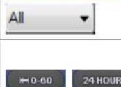 | To display the recorded data of selected channel or all channels on a time line scale. | |
| To change a timeline scale from 24 hours to 60 minutes.The timeline shows recorded data in color on the bar. You can adjust the timeline scale and move it to the time you wish to playback. Then click the play icon to display the recorded video. | ||
 | Playback buttons. | |
 | Thumbnail search over the network.- List the thumbnail 24images from 00:00 to 23:00.- Select one of 24 images every 150sec for an hour.- Then play the tile* Click the "PREVIOUS" button to go the previous step. | |
 | Digital Zoom Window in Live and Playback. (Only available in Single Channel Viewing) | |
7-6. Setup of SpecoTech Multi Client

text_image
Setup General Event Event search Record Disk Display Language About Security Option Startup Shutdown Setup Local Playback Remote Playback Password... Save Path Capture : C:\Storage\Capture\ Backup : C:\Storage\Backup\ Miscellaneous Automatic reconnection Always On Top Time Format : YYYY-MM-DD OK Cancel7-6-2. Event
Event log can be archived and searched.
Event Log: Specify the location to save event logs and select event to archive.
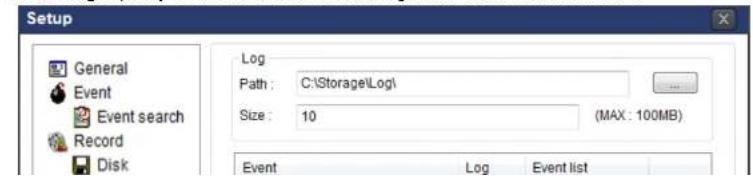
text_image
Setup General Event Event search Record Disk Log Path : C:\Storage\Log\ Size : 10 (MAX : 100MB) Event Log Event listEvent Search: Event log can be searched from the selected time.
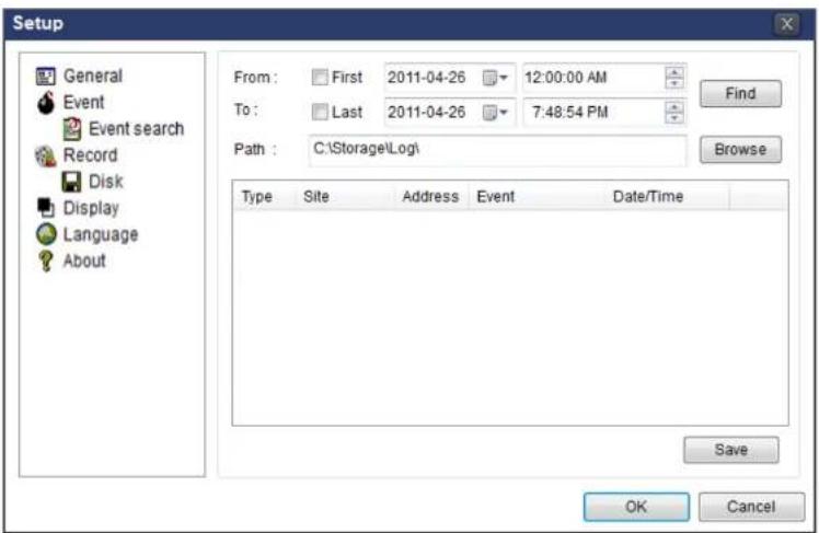
text_image
Setup General Event Event search Record Disk Display Language About From: First 2011-04-26 12:00:00 AM To: Last 2011-04-26 7:48:54 PM Path: C:\Storage\Log\( Type Site Address Event Date/Time Save OK Cancel7-6-3. Record
Record Setup: You can set the recording conditions as the following; Always, Event, or Auto record. And you can also select target ZIP and channel/channels. When you set the recording condition to event, you can set event for motion or alarm with duration.

text_image
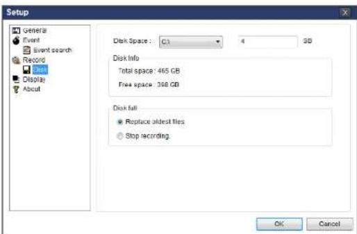
Setup General Record ConditionRecord Local Storage Setup: You can select the local disk to record and the amount of disk space you want to allow the program to use for recording. You can also select the option to overwrite data or stop recording when the maximum amount of disk space is full.

text_image
Setup General Event Event search Record Disk Display Language About Disk Space : C:\ 4 GB Disk Info Total space : 465 GB Free space : 398 GB Disk full Replace oldest files. Stop recording. OK Cancel7-6-4. Display
You can select the OSD (On Screen Display) to be displayed.
text_image
Setup General OSD7-6-5. Language
English, French and Spanish is selectable.

text_image
Setup General Event Event search Record Disk Display Language About Language: English French English Spanish OK Cancel7-6-6. About
"About" provides network client version information.
text_image
Setup General Event Event search SPECO Multi Client Version 3.1.2.5 (Build 130506)7-7. Remote Setup
The menu settings for the ZS unit can be set over network.
Put the cursor of the mouse on the channel, which is connected to the site and right click on the mouse to open the submenu. Then the following window is displayed as below. Select the REMOTE SETUP.
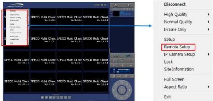
text_image
Client High Quality Normal Quality Interface Only Setup Remote Setup SPECO Multi Client SPECO Multi Client SPECO Multi Client Ver 3.1.3.1 Ver 3.1.3.1 Ver 3.1.3.1 SPECO Multi Client SPECO Multi Client SPECO Multi Client Ver 3.1.3.1 Ver 3.1.3.1 Ver 3.1.3.1 SPECO Multi Client SPECO Multi Client SPECO Multi Client Ver 3.1.3.1 Ver 3.1.3.1 SPECO Multi Client SPECO Multi Client SPECO Multi Client Ver 3.1.3.1 Ver 3.1.3.1 SPECO Multi Client SPECO Multi Client SPECO Multi Client Ver 3.1.3.1 Ver 3.1.3.1 SPECO Multi Client SPECO Multi Client SPECO Multi Client Ver: 20000000000000000000000000000000000000000000000000000000000000000000000000000000000000000000000000000 Connect High Quality Normal Quality IFrame Only Setup Remote Setup IP Camera Setup Lock Site Information Full Screen Aspect Ratio ExitThen the setup window is displayed. The specified menu screen is displayed on the upper left of the screen.
Enter the password of the ZS when prompted. (NOTE: The default password is 1111)
Setting is the same as with the ZS menu setting. Refer to the corresponding pages for details on the setting items.

text_image
SPECO WEB SETUP 17216.2.62(cgl bin/websetup.cg) SPECO WEB SETUP7-7-1. IP Camera
Select IP Camera to set system and time settings
SPECO WEB SETUP (ver 1.10.7)
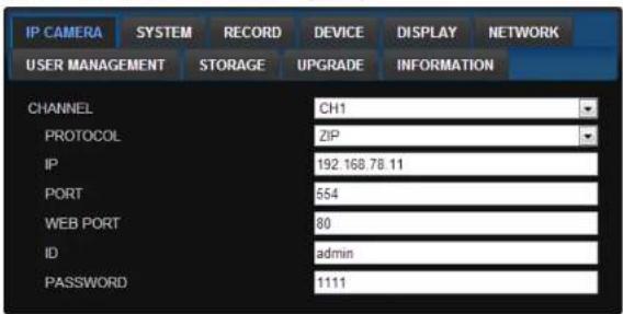
text_image
IP CAMERA SYSTEM RECORD DEVICE DISPLAY NETWORK USER MANAGEMENT STORAGE UPGRADE INFORMATION CHANNEL CH1 PROTOCOL ZIP IP 192.168.78.11 PORT 554 WEB PORT 80 ID admin PASSWORD 1111RELOAD APPLY
• CHANNEL: Select the Channel to setup an IP Camera.
o Protocol : Select the Brand of the IP Camera
- IP : Enter the IP Address of the desired Camera
o Port : Enter the Camera stream Port Number (default : 554).
- Web Port: Enter the Camera Web Port Number (default : 80).
- ID : Enter the User ID for access to the IP Camera
- PASSWORD : Enter the Password for the associated ID
7-7-2. System
Select System to set system and time settings.
SPECO WEB SETUP (ver 1.10.7)

text_image
IP CAMERA SYSTEM RECORD DEVICE DISPLAY NETWORK USER MANAGEMENT STORAGE UPGRADE INFORMATION DATE DISPLAY FORMAT MMDD/YYYY CLIENT ACCESS ON OFF NTP SETUP ON PRIMARY SNTP SERVER Pool.ntp.org SECONDARY SNTP SERVER Time.nist.gov TIME ZONE GMT -5.00 (Montreal/New York) CONNECTION MODE TIME CONNECTION PERIOD 03:00 AM SEND EMAIL SETUP OFF SERVER TYPE MANUAL MAIL SERVER MAIL PORT 25 SECURE OPTION NONE ID PASSWORD MAIL TO MAIL FROM SEND MAIL TEST APPLY MAIL SETTING & TEST UNIT NAME NVR SYSTEM RESTART SYSTEM EVENT NOTIFICATION SYSTEM RESTART HEALTH CHECK DAILY PERIOD FIRST SUN 0 H HDD TEMPERATURE 60°C 140°F HDD BAD SECTORS 10% HDD ALMOST FULL 90% EVENTS AND NOTIFICATION ALARM-OUT BEEP E-MAIL HEALTH CHECK - YES- SEND E-Mail SETUP: Sets whether to enable/disable e-mail sending function.
- SEVER TYPE: Select GMAIL, HOTMAIL, AOL, YAHOO or MANUAL)
- MAIL SERVER: Input the SMTP server name as well as the user ID and password.
- MAIL PORT: Mail port setting.
- SEURE OPTION: Select a secure mail server connection. (SSL or TLS)
○ ID : Email User ID
- PASSWORD : Email User Password
- MAIL TO: Input the appropriate email address to enable sending e-mail reports
- MAIL FROM (Return Mail Address): Set the source e-mail address to be notified to the destination.
- SEND MAIL TEST : E-mail settings sent a test mail to the registered account
• UNIT NAME: Name the ZS
• SYSTEM RESTART : Restart the system
• SYSTEM EVENT NOTIFICATION
Allows the user to set EVENT NOFICIATION ON or OFF
○ HEALTH CHECK
(Allows the user to set MAIL STATUS periodically) : DAILY or WEELY or MONTHLY
- HDD TEMPERATURE
- HDD BAD SECTOR
- HDD ALMOST FULL
o HEALTH CHECK / RESTART / SHUTDOWN / PANIC RECORD Enable Email Notification in the event a problem occurs with the ZS.
- ALARM-IN : Enable Email Notification when the camera detects sensor
- MOTION DETECTION : Enable Email Notification when the camera detects motion
- NO CONNECTION : Enable Email Beep and Alarm output Notification when the camera signal is lost
7-7-3. Record
Select RECORD tab to set the recording conditions.
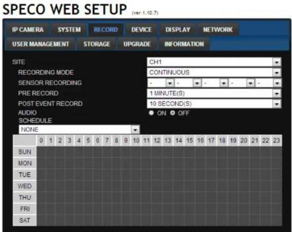
text_image
SPECO WEB SETUP (ver 1.10.7) IP CAMERA SYSTEM RECORD DEVICE DISPLAY NETWORK USER MANAGEMENT STORAGE UPGRADE INFORMATION SITE CH1 RECORDING MODE CONTINUOUS SENSOR RECORDING PRE RECORD 1 MINUTE(S) POST EVENT RECORD 10 SECOND(S) AUDIO ON OFF SCHEDULE NONE 0 1 2 3 4 5 6 7 8 9 10 11 12 13 14 15 16 17 18 19 20 21 22 23 SUN MON TUE WED THU FRI SATThese settings apply to the specified channel only.
- Recording Setup
o RECORDING MODE: CONTINUOUS, MOTION, SENSOR, SCHEDULE
o PRE RECORD: Sets whether to perform or not pre recording.
o POST EVENT RECORD: Sets the duration of the event recording.
o AUDIO: Sets audio recording ON or OFF.
o SCHEDULE: Sets the schedule recording.
7-7-4. Device
Select Device to set device settings of the ZS
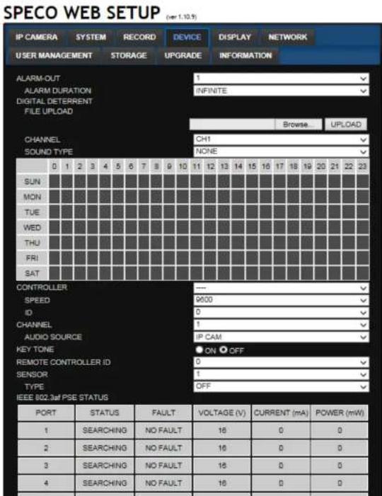
text_image
SPECO WEB SETUP (see 1.10.9) IP CAMERA SYSTEM RECORD DEVICE DISPLAY NETWORK USER MANAGEMENT STORAGE UPGRADE INFORMATION ALARM-OUT 1 ALARM DURATION INFINITE DIGITAL DETERRENT FILE UPLOAD CHANNEL CH1 NONE SOUND TYPE 0 1 2 3 4 5 6 7 8 9 10 11 12 13 14 15 16 17 18 19 20 21 22 23 SUN MON TUE WED THU FRI SAT CONTROLLER SPEED ID CHANNEL AUDIO SOURCE KEY TONE REMOTE CONTROLLER ID SENSOR TYPE IEEE 802.3af PSE STATUS PORT STATUS FAULT VOLTAGE (V) CURRENT (mA) POWER (mW) 1 SEARCHING NO FAULT 16 0 0 2 SEARCHING NO FAULT 16 0 0 3 SEARCHING NO FAULT 16 0 0 4 SEARCHING NO FAULT 16 0 07-7-5. Display
Select the DISPLAY tab to set the DISPLAY conditions.
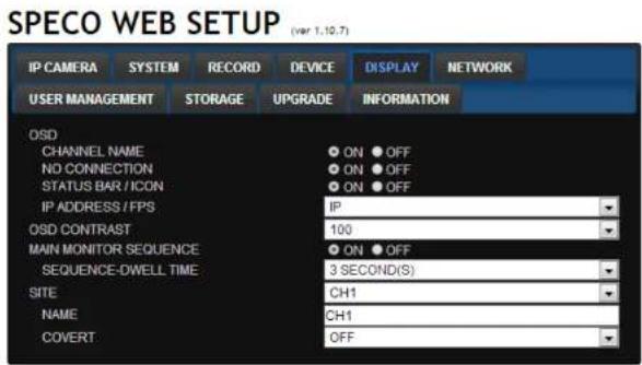
text_image
SPECO WEB SETUP (var 1.10.7) IP CAMERA SYSTEM RECORD DEVICE DISPLAY NETWORK USER MANAGEMENT STORAGE UPGRADE INFORMATION OSD CHANNEL NAME ON OFF NO CONNECTION ON OFF STATUS BAR / ICON ON OFF IP ADDRESS / FPS IP OSD CONTRAST 100 MAIN MONITOR SEQUENCE ON OFF SEQUENCE-DWELL TIME 3 SECOND(S) SITE CH1 NAME CH1 COVERT OFFThese settings apply to all channels.
- OSD: Sets whether to display or not date and time as well as channel number on the screen.
- OSD CONTRAST: Adjust the character contrast on the screen.
- MAIN MONITOR SEQUENCE: Setting for automatically switching the displayed video.
- SEQUENCE DWELL TIME: Sets the interval for automatically switching the screens.
- SITE: Name, Covert, These settings apply to the specified channel only.
7-7-6. Network
SPECO WEB SETUP (ver 1.10.7)
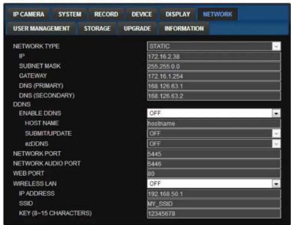
text_image
IP CAMERA SYSTEM RECORD DEVICE DISPLAY NETWORK USER MANAGEMENT STORAGE UPGRADE INFORMATION NETWORK TYPE IP 172 16.2.38 SUBNET MASK 255 255.0.0 GATEWAY 172 16.1.254 DNS (PRIMARY) 168 126.63.1 DNS (SECONDARY) 168 126.63.2 DDNS ENABLE DDNS OFF HOST NAME hostname SUBMIT/UPDATE OFF eZDDNS OFF NETWORK PORT 5445 NETWORK AUDIO PORT 5446 WEB PORT 80 WIRELESS LAN OFF IP ADDRESS 192.168.50.1 SSID MY_SSID KEY (8-15 CHARACTERS) 12345678• NETWORK TYPE (Cannot be altered remotely)
o STATIC: The address setting mode is manual. Input IP, Gateway, Subnet Mask, and DNS IP.
o DHCP: The address setting mode is automatic.
- DDNS: Set whether to use DDNS service or not
- HOST NAME: Allows the user to setup a domain name manually
SUMBIT/UPDATE: Select ON to submit the settings - ezDDNS: Enable ezDDNS to register the host name automatically
• NETWORK PORT: When connecting multiple ZSs to the network. set a unique port number.
7-7-7. User Management
Select the USER MANAGEMENT tab to set the DISPLAY conditions.
SPECO WEB SETUP (ver 1.10.7)
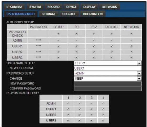
text_image
IP CAMERA SYSTEM RECORD DEVICE DISPLAY NETWORK USER MANAGEMENT STORAGE UPGRADE INFORMATION AUTHORITY SETUP PASSWORD SETUP PB PTZ REC OFF NETWORK PASSWORD CHECK ✓ ✓ ✓ ✓ ✓ ADMIN **** ✓ ✓ ✓ ✓ ✓ USER1 **** ✓ ✓ ✓ ✓ ✓ USER2 **** ✓ ✓ ✓ ✓ ✓ USER3 **** ✓ ✓ ✓ ✓ USER NAME SETUP NEW USER NAME PASSWORD SETUP CHANGE NEW PASSWORD CONFIRM PASSWORD PLAYBACK AUTHORITY USER1 USER1 ADMIN KEEP 1 2 3 4 ADMIN ✓ ✓ ✓ ✓ USER1 ✓ ✓ ✓ ✓ USER2 ✓ ✓ ✓ ✓ USER3 ✓ ✓ ✓- AUTHORITY SETUP: Select which users have access to each function, password check can be implemented for each function accessed.
- USER NAME SETUP: Select which Username to change
- NEW USER NAME: Input the new username
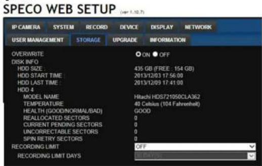
7-7-8. Storage
Select Storage to configure recording settings such as overwriting the hard disk and the setting a storage period for the recording data.
text_image
SPECO WEB SETUP (var 1.10.7) IP CAMERA SYSTEM RECORD DEVICE DISPLAY NETWORK USER MANAGEMENT STORAGE UPGRADE INFORMATION OVERWRITE ON OFF DISK INFO HDD SIZE 435 GB (FREE: 154 GB) HDD START TIME 2013/12/03 17:56:00 HDD LAST TIME 2013/12/09 17:41:00 HDD 4 MODEL NAME Hitachi HDS721050CLA362 TEMPERATURE 40 Celsius (104 Fahrenheit) HEALTH (GOOD/NORMAL/BAD) GOOD REALLOCATED SECTORS 0 CURRENT PENDING SECTORS 0 UNCORRECTABLE SECTORS 0 SPIN RETRY SECTORS 0 RECORDING LIMIT OFF RECORDING LIMIT DAYS 80 DAYS• OVERWRITE: Select on to continue recording by overwriting when the hard disk becomes full.
• DISK INFO : Hard drive information.
- RECORD LIMIT: Sets whether to limit or not the recording data storage period.
7-7-9. Remote Upgrade
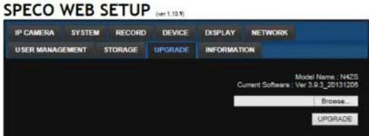
text_image
SPECO WEB SETUP (per 1.19.9) IP CAMERA SYSTEM RECORD DEVICE DISPLAY NETWORK USER MANAGEMENT STORAGE UPGRADE INFORMATION Model Name: N425 Current Software: Ver 3.9.3_20131206 Browse UPGRADE7-8. Operation via SpecoTech Multi-Client Viewer Software
7-8-1. Addition, Delete, and Modify ZS Sites
7-8-1-1. Addition of Sites
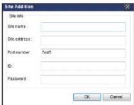
- Click SITE ADDITION button. And then the following window will be displayed as below.
text_image
Site Addition Site info: Site name: Site address: Print number: 5445 ID: Password: OK CancelSite Name: Input a name that properly describes a site.
IP Address: Input IP address (Public IP address of a router that ZS is connected.) or Domain name
- Port Number: Default Port Number is "5445".
ID: Input ID of ZS. Default ID is "admin".
- Password: Input network password of ZS. Default Password is "1111".
- Click OK button. And then the registered site is added on the directory window.

7-8-1-2. Deleting a Site
- Select the site/sites to delete from the directory window.
7-8-1-3. Modify Sites
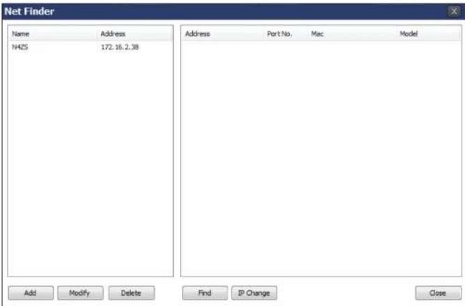
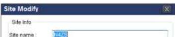
- Select the site/sites to modify from the directory window.

- Click NET FINDER button. And then the following window will be displayed as below.
text_image
Net Finder Name Address NHZ5 172.16.2.38 Address Port No. Mac Model Add Modify Delete Find JP Change Close- Click MODIFY button and then the modified information is displayed as below.
7-8-2. Connect and Disconnect
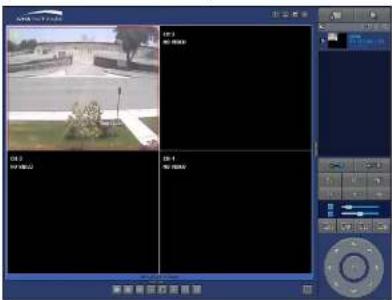
7-8-2-1. Connect
- Select site/sites to connect from the directory window.

- Click CONNECT button, and then site/sites displays/display as connected.
text_image
Screenshot of a video editing software interface showing a surveillance camera with real-time status and channel controls7-8-2-2. Disconnect
- Select site/sites to disconnect from the directory window.

- Click DISCONNECT button, and then selected site/sites disconnected.
7-8-3. Still-Image Capture During Live
- Double-click a channel to capture from the display screen. (Otherwise all channels will be captured).

text_image
Street photo with visible store signboards and a red arrow indicating transformation from left to right.- Click CAPTURE button. And then the Capture window will be displayed as below.

text_image
Capture Save Path: ersUPLIM\Documents\Speco\Capture\N4ZS Browse File name: 2013-11-18-135153 File Format: BITMAP(*.BMP) OK Cancel- Set Save Path, File Name, and File Format. And then click OK button.
- Still image is saved as set in Capture window.
7-8-4. Recording Video on Local PC During Live
- Click SETUP button and then a setup window will be displayed as below.
-
Select Record and set the values.
-
Select Disk and set the values.
text_image
Setup General Event Event search Record and Display About Disk Space : C:\ 4 SB Disk Info Total space: 465 GB Free space: 398 GB Disk full ● Replace oldest files ○ Stop recording. OK Cancel-
Click RECORD ON button. And the color of button is changed.
-
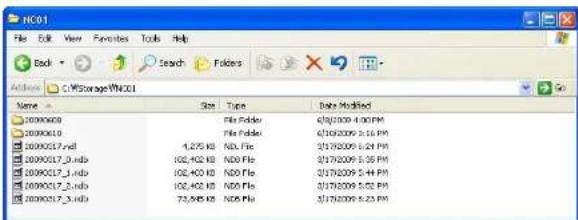
Live video data is recorded as set in Record and Disk setup. These video data can be searched and play-backed with Local Playback.
text_image
HC01 File Edit View Favorites Tools Help Back Search Folders C:\Storage\HC01 Name Size Type Date Modified 20090608 File Folder 01/2009 4:00 PM 20090610 File Folder 01/2009 5:16 PM 20090617.ind 1,275 KB ND. File 2019209 6:24 PM 20090617_3.ind 102,402 KB ND. File 2019209 8:38 PM 20090617_3.ind 102,402 KB ND. File 2019209 9:44 PM 20090617_3.ind 102,402 KB ND. File 2019209 5:02 PM 20090617_3.ind 73,545 KB ND. File 2019209 8:23 PM7-8-5. Local Playback and Remote Playback
7-8-5-1. Playback of Recorded Video on a Local PC
- Click LOCAL PLAYBACK. And then Playback Window will be displayed over the Live
Window.
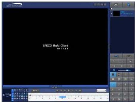
text_image
SPECO Multi Client View 3.0.4.4-
Select site/sites to connect from the directory window.
-
Click CONNECT button. And then Green bar displays on Search calendar and timeline scale window.

text_image
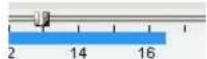
2013 May S M T W T F S 1 2 3 4 6 7 8 9 10 11 13 14 15 16 17 18 29 30 22 23 24 25 27 28 29 30 31 0 2 4 6 8 10 12 14 16 18 EZSearch AI- Move the marker on the timeline scale to where there is video data and press the PLAY button.

7-8-5-2. Playback of Recorded Video on Remote ZS
- Click

REMOTE PLAYBACK. And then Playback Window will be displayed over the Live
Window.

text_image
SPECO Hulo Client Vor 1.0.2.6-
Select the site to connect from the directory window.
-
Click

And then Green bar displays on Search calendar and timeline scale window.

text_image
2013 May S M T W T E S 1 2 3 4 5 6 7 8 9 10 11 12 13 14 15 16 17 18 19 20 21 22 23 24 25 26 27 28 29 30 31 0 2 4 6 8 10 12 14 16 18 EZ Search All- Move the marker on the timeline scale to where there is video data and press the PLAY button.
7-8-6. AVI Backup during Playback
You can back up the recorded videos in AVI format during playback.
- Double-click the target channel to backup.
- Select the beginning time by using the search calendar and timeline scale bar.

text_image
2013 Nov S M T W T F S 1 2 3 4 5 6 7 8 9 10 11 12 13 14 15 16 17 18 19 20 21 22 23 24 25 26 27 28 29 30 0 2 4 6 8 10 12 14 16 18 20 22 24 EZ Search All- Click EZCOPY START button on the timeline scale to select the beginning point of the backup.

text_image
0 10 20 30 40 50 60- Click EZCOPY END button on the timeline scale to select the ending point of the backup. Then, the selected starting point and the ending point on the timeline scale bar will be marked in green.
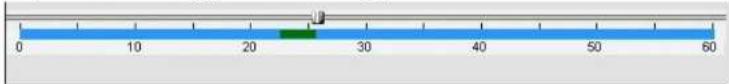
text_image
0 10 20 30 40 50 60- Click BACKUP. And then the BACKUP window will be displayed as below.
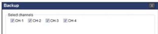
text_image
Backup Select channels ✓ CH-1 ✓ CH-2 ✓ CH-3 ✓ CH-4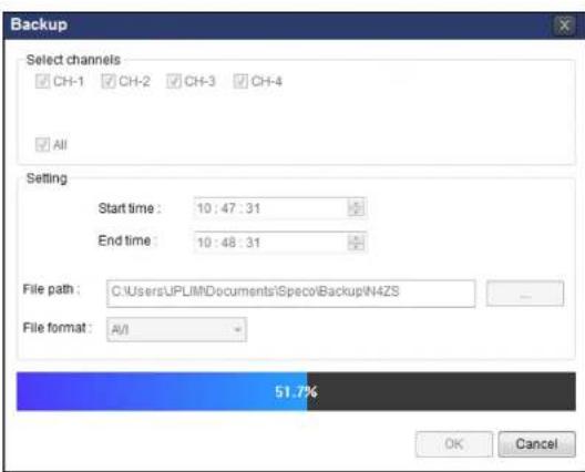
text_image
Backup Select channels CH-1 CH-2 CH-3 CH-4 All Setting Start time: 10:47:31 End time: 10:48:31 File path: C:\UsersUPLIM\Documents\Specol\Backup\N4ZS File format: A/I 51.7% OK Cancel- AVI video data is recorded as set in AVI Backup window. AVI format video can be played back by using Window Media Player™ or other media player that is compatible with AVI format video.
natural_image
Exterior view of a construction site with excavated earth, bare trees, and adjacent buildings under clear sky (no signage or text visible)7-9. ZIP IP Camera Setup
The menu settings for the ZIP IP Cameras can be set over network via SpecoTech Multi client Software. Put the cursor of the mouse on the channel, which is connected to the site and right click on the mouse to open the submenu. Then the following window is displayed as below. Select the IP CAMERA SETUP.

text_image
space technology Document High Quality Normal Quality IFrame Only Setup Remote Setup IP Camera Setup Lock Off Features Lock Adjust Auto CH1 CH2 NO VIDEO Connect High Quality Normal Quality IFrame Only Setup Remote Setup IP Camera Setup Lock Site Information Full Screen Aspect Ratio CH 1 CH 2 CH 3 CH 4Then the setup window is displayed. The specified menu screen is displayed on the upper left of the screen. Enter the password of the IP Camera when prompted.
(NOTE: The default ID : "admin" and Password is "1111")
7-9-1. Live View

text_image
speco technologies TREE7-9-2. Video
text_image
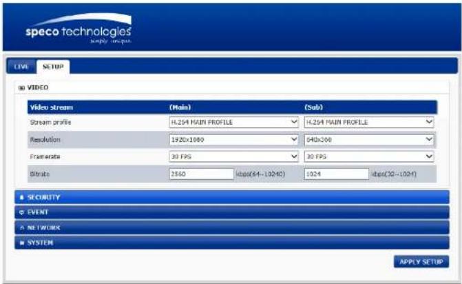
speco technologies LIVE SETUP VIDEO Video stream (Main) (Sub) Stream profile H.254 MAIN PROFILE H.254 MAIN PROFILE Resolution 1920x1080 640x300 Framescale 30 FPS 30 FPS Rate 3350 kbps(64-102kΩ) 1024 kbps(30-102kΩ) SECURITY EVENT NETWORK SYSTEM APPLY SETUP■ VIDEO Stream (MAIN/SUB)
- Stream profile : The standard defines various sets of capabilities, which are referred to as profiles, targeting specific classes of applications.
- Resolution : Select video compression resolution. Compression resolutions are different depending on input formats.
- Framerate : Determine the maximum number of frames of video images to compress. The frame rate of actually transmitted video can be affected by the network bandwidth limitation
- Bitrate : Selectable video Bit rate. This selection is available if Preference is set to 'Bit rate'
7-9-3. Security
7-9-4. Event

text_image
speco technologies' only support LIVE SETUP VIDEO SECURITY EVENT Motion defetion Set area FULL ZONE Sensitivity 5 NETWORK SYSTEM APPLY SETUP■ Motion Detection : Select Motion Detection function
- SET AREA : Configure regions for motion detection
- Sensitivity: Set the condition to trigger an event for motion detection. The value determines the sensitivity of the motion detection within a block: the smaller, the more sensitive
7-9-5. Network

text_image
speco technologies' supply design LIVE SETUP S VIDEO B SECURITY B EVENT7-9-6. System
text_image
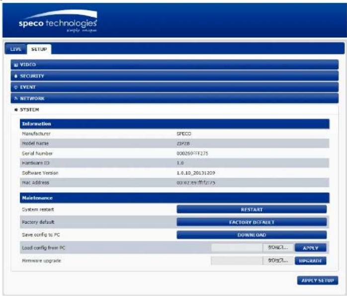
speco technologies LIVE SETUP VIDEO SECURITY EVENT NETWORK SYSTEM Information Manufacturer SPECO Model name ZIP28 Serial Number 000269-FT275 Hardware ID 1.0 Software Version 1.0.10_20131209 Mac address 00:02:25 布户275 Maintenance System restart RESTART Factory default FACTORY DEFAULT Save config to PC DOWNLOAD Load config from PC $0美元... Hardware upgrade $0美元... UPGRADE APPLY APPLY SETUPInformation
- Manufacturer
- Model Name
- Serial Number
● Hardware ID : Display the Network Hardware ID of the camera recognized by system
Press Browse button to select a firmware file from PC.
Press Firmware Upgrade button to start to upgrade.
Messages for showing status (downloading / upgrading) will be displayed.
The camera will reboot automatically after completing upgrade. Do not turn the camera off during upgrading
8. Network Access Using SpecoTech Web Viewer
The ZS provides a live remote monitoring feature via SpecoTech Web Viewer.
(NOTE: Web-Browser is only available for Internet Explorer)
- Check the IP address of the ZS from SETUP>SYSTEM>DESCRIPTION>IP ADDRESS or
- Input the IP address or Domain name address that you pre-registered.

- Click this bar. Then the dialog box is displayed.

text_image
This webpage wants to run the following add-on: 'CNC_Ctrl Module' from 'Not Available'. What's the risk? Allow This website wants to install the following add-on: 'speco_control(ver1.6.3.7)' from 'Speco Technologies'. What's the risk? Install- Click "Install" to download and install the ActiveX control.

text_image
User Account Control Do you want to allow the following program to make changes to this computer? Program name: SpecoTech-WebViewer(verL4.8.7) Verified publishers: Speco Technologies File origin: Downloaded from the Internet Show details Yes No Change when these notifications appear-
The Web Viewer will be displayed as below after the ActiveX installation
-
Click the CONNECT button on the Left upper corner of web-viewer. Then "Connect" dialog is displayed.
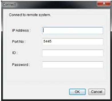
text_image
Connect Connect to remote system. IP Address : Port No : 5445 ID : Password : OK Cancel- Site Name: Input a name that properly describes a site.
- IP Address: Input IP address (Public IP address of a router that ZS is connected.) or Domain name
• Port Number: Default Port Number is "5445".
• ID: Input ID of ZS. Default ID is "admin". -
Password: Input network password of ZS. Default Password is "1111".
-
Then the cameras connected to the ZS are displayed on the screen.
- Use mouse scroll to digitally zoom in and out from a single channel display.

text_image
File Edit View Insert View Search 2014-06-01 09:33:13 Service Technologies C# 29. Network Access Using the Smart Phone Viewer

Notice
Data Usage applied without Wi-Fi connection. Please check with your Phone Carrier.
9-1. App Viewer for iPhone
- Enter the Apple iTunes Store.

- Search "Speco Player" in the App Store.

Notice
SPECO Player is for the ZS, NS, DS, RS, their Wall Mount versions and HD series. SPECO Player is not compatible with the CS/LS/PS/GS Models, the T Series (TH, TN or TL) or the PC Series.
9-1-1. Live
- Open the installed "Speco Player" App and click button to add a remote device.

-
Enter the site name, IP or DDNS address, Network Port number (default 5445), ID(default admin) and Password (default 1111). Then. click "Save" buon.
-
The app will display the selected channel(s). Double tap the channel screen to switch 1 channel display to 4 or 8 channels split display depending on the ZS.
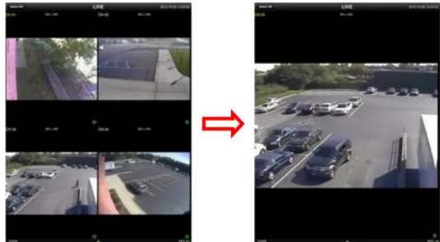
text_image
Side-by-side comparison of surveillance camera frames showing outdoor scenes and vehicle detection, with a red arrow indicating the process.- To select the display mode(1, 4, 9, 10 or 16 split display), tap the arrow menus button

text_image
Photo LYPE 01:00 01:01 01:02 01:03 01:04 01:05 01:06 01:07 01:08 01:09 01:10 01:11 01:12 01:13 01:14 01:15 01:16 01:17 01:18 01:19 01:20 01:21 01:22 01:23 01:24 01:25 01:26 01:27 01:28 01:29 01:30 01:31 01:32 01:33 01:34 01:35 01:36 01:37 01:38 01:39 01:40 01:41 01:42 01:43 01:44 01:45 01:46 01:47 01:48 01:49 01:50 01:51 01:52 01:53 01:54 01:55 01:56 01:57 01:58 01:59 01:60 01:61 01:62 01:63 01:64 01:65 01:66 01:67 01:68 01:69 01:70 01:71 01:72 01:73 01:74 01:75 01:76 01:77 01:78 01:79 01:80 01:81 01:82 01:83 01:84 01:85 01:86 01:87 01:88 01:89 01:90 01:91 01:92 01:93 01:94 01:95 01:96 01:97 01:98 01:99 02:009-1-2.PTZ Control
To control the PTZ funcons of the camera, tap the menu buon. Then PTZ menu icons will display. Using the PTZ icon on the screen, control PTZF control.
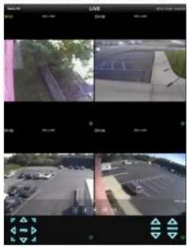
natural_image
Three-panel surveillance camera view showing outdoor scenes with vehicles and buildings (no visible text or symbols)9-1-3. Playback
- Select Mode as 'Playback' and click 'CONNECT' buon. Then select Date & Time and click PLAY buon.

text_image
Device List Demo ZS Connect Playback Live Site Information: File: Demo ZS ID:DNS: demoZS.dina.specodides.net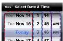
- Tap the menu buon. Then Playback menu Icons will display.

text_image
1 4 9 10 16 Now Minute Hour Day 8x 6x9-2. App Viewer for Android Phone
- Enter the Google Play Store.

- Search "Speco Player" in the Android Market and install the "Speco Player" App.

Notice
SPECO Player is for the DS, RS, WRS, NS and ZSs. SPECO VIEWER is not compatible with the T Series NS's (TH, TN or TL) or the PC Series NS's.
9-2-1. Live
- Open the installed "Speco Player" App and select the Live Preview. Then click the menu buon of the phone to add a remote device.
- Select the registered device and select LIVE VIEW and select up to 4 channels to monitor. Then click START buon.

- The app will display the selected channel(s). Double tap the channel screen to switch 1 channel display to 4 channels split display.
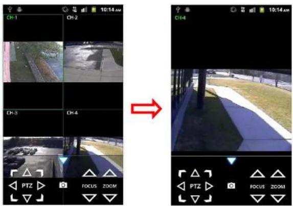
text_image
OH-1 OH-2 OH-3 OH-4 PTZ FOCUS ZOOM 10:14 AM 10:14 AM PTZ FOCUS ZOOM9-2-2. Playback
- Select the registered device and select PLAYBACK and select up to 4 channels to search. Then click START buon.
- The app will display the selected channel(s). Double tap the channel screen to switch 1 channel display to 4 channels split display.


9-2-3. PTZ Control
To control the PTZ funcon of the camera, tap the channel screen, then the channel name will be highlighted in Yellow. Using the PTZ menu icons on the screen, control PTZF.
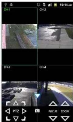
text_image
CH-1 CH-2 CH-3 CH-4 PTZ FOCUS ZOOM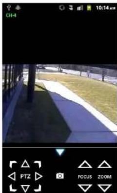
natural_image
Outdoor scene with a paved path, grassy area, and trees under a fence (no visible text or symbols)APPENDIX: Network Connection - LAN

flowchart
graph LR
    A["Internet"] --> B["Cable Modem"]
    B --> C["Router"]
    C --> D["Computer"]
- Run the network client software.
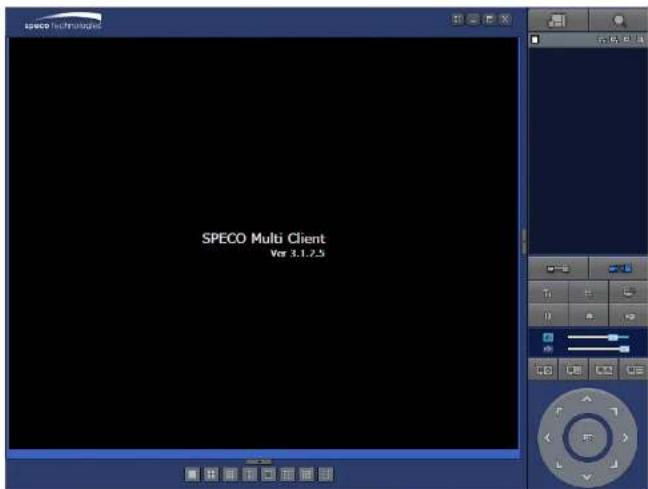
text_image
SPECO Multi Client Ver 3.1.2.5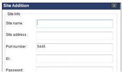
text_image
Site Addition Site Info Site name: Site address: Port number: 5445 ID: Password:- Select a site by checking the box, and Press
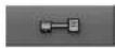
button to connect to the site.
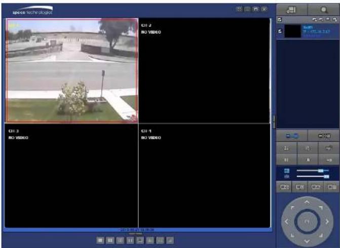
text_image
space technologies CH 2 NO VIDEO CH 3 NO VIDEO CH 4 NO VIDEO 20+视频监控系统APPENDIX: Network Connection – Internet and DDNS
Dynamic Domain Name System (DDNS) allows a domain name to be constantly synchronized with a dynamic IP address. A current dynamic IP address is being associated with a static domain name.
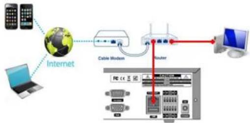
flowchart
graph TD
    A["Internet"] --> B["Cable Modem"]
    B --> C["Router"]
    C --> D["Computer"]
    A --> E["Laptop"]
    A --> F["Mobile Phone"]
    style A fill:#f9f,stroke:#333
    style B fill:#ccf,stroke:#333
    style C fill:#cfc,stroke:#333
    style D fill:#fcc,stroke:#333
    style E fill:#ffc,stroke:#333
    style F fill:#cfc,stroke:#333
- Go to SETUP>NETWORK>DDNS and set the DDNS SERVER to ON.
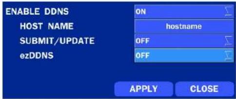
text_image
ENABLE DDNS HOST NAME SUBMIT/UPDATE ezDDNS ON hostname OFF OFF APPLY CLOSEIf you set ezDDNS to ON, the host name is automatically generated and registered.
- Go to SETUP>NETWORK>DDNS>HOST NAME. Manually enter a domain name using the virtual keyboard and click ENTER button.

- When you exit SETUP menu, DDNS NOTIFY window will pop up.

text_image
DDNS NOTIFY : HOST NAME : n4zs_fff2e2 STATUS : SUCCESS OK DDNS NOTIFY : HOST NAME : hostname STATUS : ALREADY REGISTERED OK- DDNS registration status can be checked from SYSTEM INFORMATION or SETUP>SYSTEM>DESCRIPTION>DDNS STATUS

text_image
MODEL NAME N4ZS SOFTWARE VERSION Ver 3.8.2_20131113 STORAGE SIZE 870 GB NETWORK TYPE STATIC IP ADDRESS 172.16.2.38 MAC ADDRESS 00:02:69:FF:F2:E2 DDNS STATUS DDNS OFF UNIT NAME NVR REMOTE CONTROLLER ID 0 OK- Check the NETWORK PORT (Default: 5445), WEB PORT (Default: 80), and the IP Address of the ZS from SETUP>NETWORK.

text_image
NETWORK NETWORK TYPE IP SUBNET MASK DHCP 172.16.2.38 255.255.0.0- Run the network client software.
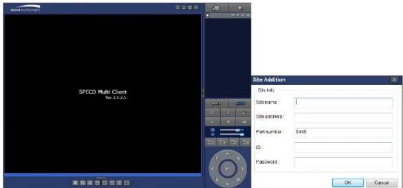
text_image
SPECD Multi Client Ver 3.1.2.5 Site Addition Site Info Site name : Site address : Port number: 5446 ID: Password : OK Cancel-
Input Site Name, Site Address (IP address), Port No., and Password on the connect window.
-
Site Name: Input a name that properly describes a site.
• IP Address: Domain name or Public IP address of a router that ZS is connected.
• Port Number: Default Port Number is "5445".
• ID: Input ID of ZS. Default ID is "admin". -
Password: Input network password of ZS. Default Password is "1111".
-
And select the OK button. Then, press