
MCAES3 - Audio Equipment Lectrosonics - Free user manual and instructions
Find the device manual for free MCAES3 Lectrosonics in PDF.

| Product Type | Digital Audio Cable |
| Connector 1 | 5-pin TA5F Female |
| Connector 2 | 3-pin Female XLR |
| Cable Length | 18 inches (45.7 cm) |
| Cable Type | RG-174U Coaxial |
| Application | Connect SPDR recorder output to AES3 digital input of mixer or recorder |
| Compatible Devices | Lectrosonics SPDR Recorder; Devices with AES3 digital input |
| Signal Type | AES3 Digital Audio |
| Connector Contacts | Soldered |
| Weight | Approx. 0.1 lb (45 g) |
| Color | Black (typical) |
| Brand | Lectrosonics |
| Model | MCAES3 |
Frequently Asked Questions - MCAES3 Lectrosonics
User questions about MCAES3 Lectrosonics
0 question about this device. Answer the ones you know or ask your own.
Ask a new question about this device
Download the instructions for your Audio Equipment in PDF format for free! Find your manual MCAES3 - Lectrosonics and take your electronic device back in hand. On this page are published all the documents necessary for the use of your device. MCAES3 by Lectrosonics.
USER MANUAL MCAES3 Lectrosonics
1) Install batteries (or connect to external power) and turn the power on (p. 5).
2) Insert microSDHC memory card and format it with the SPDR (p. 6).
3) Jam to a timecode source, if needed.(p. 10).
4) Connect microphone or audio source (p. 7).
5) Set input type and level, if analog source (p.12).
6) Select record mode (p. 11).
7) Set output level (HP Volume p. 10).
8) Begin recording (p.8).
micro™
SPDR
Table of Contents
Quick Start Steps....1
Technical Highlights....4 Broadcast Wave Format....4
Broadcast Wave Format....4
IXML HEADER SUPPORT 4
Standard TA5 mic/line inputs....4
AES3 Digital Input....4
Timecode Support 4
Dual Sample Rates 4
Linked vs. Independent Stereo 4
Split Gain Mode 4
Dual Power Sources 4
Power Options 5
Battery Installation 5
Power Input Connector 5
Preparing a MicroSDHC Memory Card....6
iXML HEADER SUPPORT 6
Features and Controls 7
Settings 7
Powering On 8
Powering Off 8
Recording Screens 8
Navigating Menus....9
Main Menu and Sub Menus ....10
Timecode 10
Inputs 10
HP Volume 10
Scene & Take 10
SD Card 10
Settings 11
About SPDR....11
Default 11
Operating Instructions....12
Recording in Analog Mode....12
Recording in Digital Mode....12
Browsing/Playing Back Recordings 13
Copying Recordings to a Computer....14
Recovering an Interrupted Recording....14
Locking and Unlocking the Settings....15
Using a Remote Control App....15
5-Pin Input Jack Wiring 16
Microphone Cable Termination for Non-Lectrosonics Microphones 17
Input Jack Wiring for Different Sources ....18
SPDR
Introduction
The second recorder from Lectrosonics, the SPDR (Stereo Portable Digital Recorder) delivers advanced technology and features, including stereo mode with two channels available. As a backup recorder in a bag, the recorder is small, yet packed with features, including extended run time, optional external power and higher sample rates.
On occasion, there is a need to record high quality, stereo audio in circumstances where a traditional full sized recorder is impractical or when a reliable backup is needed. When talent is at an extreme distance or using a wireless microphone is not practical (knights in armor come to mind), the SPDR can travel with your subject and record professional quality stereo audio, synchronized with timecode.
The SPDR can be tethered to a camera to capture a higher quality or backup audio recording. The headphone output doubles as a line output to feed the AV input on a camera.
Setup and adjustment is made through an intuitive interface provided by the keypad and LCD. The housing is an aluminum extrusion with machined aluminum top and control panels, as well as a hard anodized finish.
Technical Highlights
Broadcast Wave Format
With a timecode jam at the start of the production, the audio data file contents include a timing reference to make it easy to synchronize them in the time line. The industry standard BWF/.WAV file format is compatible with essentially any audio or video editing software.
iXML HEADER SUPPORT
Recordings contain industry standard iXML chunks in the file headers with the most commonly used fields.
Timecode Support
Timecode can be copied from the internal real time clock, for projects where it is desirable for timecode to approximately match time of day but it is not necessary to keep time with other devices.
Timecode defaults to zero at power up if no timecode source is used to jam the unit. A timing reference is logged into the BWF metadata.
Dual Sample Rates
The SPDR has two sample rate options available; 48 kHz is an industry standard rate and should be suitable for nearly all purposes. At 96 kHz, the microSDHC memory card will be used up twice as fast, but will have slightly less phase distortion near the top end of the audible spectrum (close to 20 kHz).
Linked vs. Independent Stereo
The Linked Stereo option operates limiters on both channels together to preserve the balance of the stereo image. Use Independent Stereo when you have two separate sounds/voices and each input will have a separate limiter.
Split Gain Mode
There are two recording modes available in the menu, HD Mono, which records a single audio track and Split Gain, which records two different tracks, one at the normal level and another at -18 dB as a "safety" track that can be used in place of the normal track in the event that overload distortion (clipping) has occurred on the normal track. In either mode, recordings over 4GB are broken into sequential segments so very long recordings (over approx 5 hours in HD mode or 2.5 hours in split mode) will not be a single file.
Dual Power Sources
The SPDR has an external power input with internal
Power Options
Battery Installation
The audio recorder is powered by two AA Lithium batteries. Zinc-carbon batteries marked "heavy-duty" or "long-lasting" are not adequate.
Push outward on the battery compartment door and lift it to open.
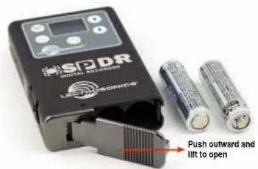
Insert the batteries according to the markings on the back side of the housing.
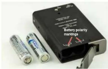
Power Input Connector
The SPDR is designed to be used with the DCR12/A5U external (or equivalent) power source. The nominal voltage to operate the unit is 12 VDC, although it will operate at voltages as low as 6 VDC and as high as 17 VDC. External power sources must be able to supply 200 mA continuously.
NOTE: There is an automatic switch over to battery if power is interrupted.
natural_image
Product photo of a black electronic device with attached charging cable and power plug (no visible text or symbols)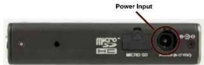
SPDR
Preparing a MicroSDHC Memory Card
Compatible Cards
We have tested a wide variety of cards and these performed the best with no issues or errors.
- Lexar 16GB High Performance UHS-I (Lexar part number LSDMI16GBBNL300).
- SanDisk 16GB Extreme PLUS UHS-I (SanDisk part number SDSDQX-016G-GN6MA)
• Sony 16GB UHS-I (Sony part number SR16UXA/TQ) - PNY Technologies 16GB Elite UHS-1 (PNY part number P-SDU16U185EL-GE)
• Samsung 16GB PRO UHS-1 (Samsung part number MB-MG16EA/AM)
Installing Card
The card slot is covered by a flexible cap. Open the cap by pulling out on the side flush with the housing.

Pull up on this side of cap to open
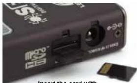
When a card is installed, or when the SPDR is powered on with a card already installed, the card is scanned to see if it has been formatted for use with the SPDR. If it hasn't, a prompt appears offering to do so. Follow the on-screen prompts to format the card. If the scan finds an interrupted recording, the Recovery screen will appear. The formatting operation may also be performed on a card whish is already formatted, to erase all recordings and start over with an empty card. To do this, select Format Card from the menu.
WARNING: DO NOT PERFORM A LOW LEVEL FORMAT (COMPLETE FORMAT) WITH A COMPUTER. DOING SO MAY RENDER THE MEMORY CARD UNUSABLE WITH THE SPDR RECORDER. WITH A WINDOWS BASED COMPUTER, BE SURE TO CHECK THE QUICK FORMAT BOX BEFORE FORMATTING THE CARD.
IMPORTANT
The formatting of the SPDR SD card sets up contiguous sectors for maximum efficiency in the recording process. The file format utilizes the BEXT (Broadcast Extension) wave format which has sufficient data space in the header for the file information and the time code imprint.
The SD card, as formatted by the SPDR, can be corrupted by any attempt to directly edit, change, format or view the files on a computer.
The simplest way to prevent data corruption is to copy the .wav files from the card to a computer or other Windows or OS formatted media FIRST. Repeat - COPY THE FILES FIRST!
Do not rename files directly on the SD card.
Do not attempt to edit the files directly on the SD card. Do not save ANYTHING to the SD card with a computer (such as the take log, note files etc) - it is formatted for SPDR use only.
Do not open the files on the SD card with any third
Features and Controls

The audio input circuitry is essentially the same as on Lectrosonics SM and L Serles transmitters. Any microphone wired as Lectrosonics "compatible" or "servo bias" will work with the SPDR.
The Power LED is green when the SPDR is running on battery power. When recording, the light will flash green. Once battery power is low (30 minutes remaining), the LED will turn red. Once the red LED begins flashing, the SPDR can die at any moment.
The Power LED is blue when the SPDR is running on external power. When recording, the light will flash blue. If both batteries and external power are connected to the SPDR, it will run on external power and the LED will be blue.
Last, the LED will briefly blink blue rapidly on receiving a successful time code jam.
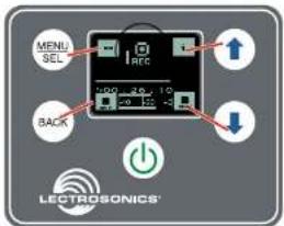
Settings
Settings are accessed by pressing MENU/SEL on the keypad, and then using the UP and DOWN arrow buttons and BACK button to navigate the menu items and select functions. The buttons also provide alternate functions as labeled by the soft buttons (or icons) on the
The main functions of SPDR, Record, Stop Recording, Playback are revealed by the status indicator. Both the status indicator and soft buttons change to accommodate the current SPDR function.
In Playback Mode, the soft buttons on the LCD change to provide the functions needed during playback. There are three variants of playback:
• active playback
• paused playback in the middle of the recording
• paused playback at the end of the recording
The soft buttons in the corners of the LCD and the status indicator will change depending on the status of the playback.

SPDR
Powering On
Press and hold the Power Button until the Lectrosonics logo appears on the LCD.
Powering Off
Power can be turned off by holding the Power Button in and waiting for the countdown. The Power Button will not work while the unit is recording (stop recording first before powering down) or if the SPDR has been locked (unlock the recorder first).
If the power button is released before the countdown reaches 3, the unit will remain turned on and the LCD will return to the same screen or menu that was displayed previously.
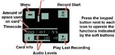
Recording Screens
While recording, the screen provides a view of the battery status, timecode and the input audio level. Soft buttons in the four corners of the screen provide access to the Menu, Info (available recording time if microSDHC memory card installed, SPDR info if no card in unit), and the REC (record start) and LAST (play last clip) functions. These functions are invoked by pressing the adjacent keypad button as shown on the previous page.
Battery status
The status indicator will alert you if there is no microSDHC memory card in the SPDR.

Press and Hold BACK and DOWN arrow to stop recording
If both buttons are not pressed to stop recording, you will receive this reminder.

Stereo Portable Digital Recorder
Navigating Menus

flowchart
graph TD
    A["Inputs..."] --> B["SEL"]
    B --> C["Input Level"]
    C --> D["Input Type"]
    D --> E["Stave Mode"]
    E --> F["LF Rolloff"]
    F --> G["HP Volume"]
    G --> H["Sceled/Take"]
    H --> I["SD Card..."]

    B --> J["SEL"]
    J --> K["Back"]

    C --> L["Input Level"]
    L --> M["Input Type"]
    M --> N["Stave Mode"]
    N --> O["LF Rolloff"]

    G --> P["SCE"]
    P --> Q["SFL"]
    Q --> R["Back"]

    H --> S["Scened/Take"]
    S --> T["SCL"]
    T --> U["Back"]

    H --> V["SD Card..."]
    V --> W["SCL"]
    W --> X["Back"]

    L --> Y["Input Level"]
    Y --> Z["Input Type"]
    Z --> AA["Stave Mode"]
    AA --> AB["LF Rolloff"]

    M --> AC["HP Volume"]
    AC --> AD["Sceled/Take"]
    AD --> AE["SCL"]
    AE --> AF["Back"]

    Y --> AG["Input Level"]
    AG --> AH["Input Type"]
    AH --> AI["Stave Mode"]
    AI --> AJ["LF Rolloff"]

    M --> AK["HP Volume"]
    AK --> AL["SCE"]
    AL --> AM["SCL"]

    Y --> AN["Scened/Take"]
    AN --> AO["SCL"]
    AO --> AP["SCL"]

    M --> AQ["Input Level"]
    AQ --> AR["Input Type"]
    AR --> AS["Stave Mode"]
    AS --> AT["LF Rolloff"]

    M --> AU["HP Volume"]
    AU --> AV["SCE"]
    AV --> AW["SCL"]

    M --> AX["SCL"]
    AX --> AY["SCL"]

    Y --> AZ["SCL"]
    AZ --> BA["SCL"]

    M --> BB["SCL"]
    BB --> BC["SCL"]

    M --> BD["SCL"]
    BD --> BE["SCL"]

    M --> BF["SCL"]
    BF --> BG["SCL"]

    M --> BH["SCL"]
    BH --> BI["SCL"]

    M --> BJ["SCL"]
    BJ --> BK["SCL"]

    M --> BL["SCL"]
    BL --> BM["SCL"]

    M --> BN["SCL"]
    BN --> BO["SCL"]

    M --> BP["SCL"]
    BP --> BQ["SCL"]

    M --> BR["SCL"]
    BR --> BS["SCL"]

    M --> BT["SCL"]
    BT --> BU["SCL"]

    M --> BV["SCL"]
    BV --> BW["SCL"]

    M --> BX["SCL"]
    BX --> BY["SCL"]

    M --> BZ["SCL"]
    BZ --> CA["SCL"]

    M --> CB["SCL"]
    CB --> CC["SCL"]

    M --> CD["SCL"]
    CD --> CE["SCL"]

    M --> CF["SCL"]
    CF --> CG["SCL"]

    M --> DH["SCL"]
    DH --> DI["SCL"]

    M --> DJ["SCL"]
    DJ --> DE["SCL"]

    M --> DF["SCL"]
    DF --> DG["SCL"]

    M --> DH
    DH --> DE
SPDR
Main Menu and Sub Menus
Timecode
TC Jam (jam timecode)

When TC Jam is selected, JAM NOW will flash on the LCD and the unit is ready to be synced with the timecode source. Connect the timecode source and the sync will take place automatically. When the sync is successful, a message will be
displayed to confirm the operation.
Timecode defaults to zero at power up if no timecode source is used to jam the unit. A timing reference is logged into the BWF metadata.
Frame Rate
The frame rate affects embedding of the timing reference in the BWF file metadata and display of timecode. The following options are available:
NOTE: While it is possible to change the frame rate, the most common use will be to check the frame rate which was received during the most recent timecode jam. In rare situations, it might be useful to alter the frame rate here, but be aware that audio tracks many not line up correctly with mismatched frame rates.
Use Clock
Choose to use the clock provided in the SPDR as opposed to a timecode source. Set the clock in the Settings Menu, Date & Time on next page.
channel, but the audio bar graph meters will operate independently.
Independent:
Use this mode if you are recording two separate sounds/voices, and each input will have a separate limiter.
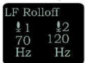
NOTE: Input Level and LF Rolloff screens have one control in Linked Mode and two controls in Independent Mode.
LF Rolloff
Press MENU/SEL to select which input to adjust. Adjust with the UP and DOWN arrow buttons.
HP Volume
Use UP and DOWN arrows to adjust headphone volume.
Scene & Take
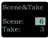
Each time a recording is started, the SPDR automatically increments take. Scene and Take numbers can be manually updated. Takes can run up to 999 and scene number can run up to 99.
The progressive scene and take automatically catalogo each time a recording is begun; S01T001.WAV. The initial 'S' is meant to suggest "Scene" but also serves as the overwrite prevention character, decrementing to 'R', 'Q', etc. as needed to avoid a naming conflict. The "01" after the 'S' is the scene number. 'T' means take, and the "001" is the take number. An eighth character is used only for the second and subsequent (4 GB) segments for very large recordings. Scene numbers are entered manually. Take numbers increment automatically.
SD Card
Takes/Play
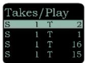
Choose to play the files based on scene and take. Use the arrows to scroll, MENU/SEL to select the file and the DOWN arrow to play.
File Naming
File naming can be set as Sequence, Clock Time or Scene/Take. Use the arrows to scroll, MENU/SEL to choose.
About Card
View information about the microSDHC memory card See storage used, storage capacity and available recording time.
![[SPDR] Fuel gauge Storage capacity Available recording time (H : M : S) Max Rec Time 14:24:42](/content/2026/06/1216268/images/c09237fbd906b4a24f96640f51433fb105d5cd2645a7665633c78f36940b6311.jpg)
Settings
Record Mode
Two record modes are available:
HD Stereo: Records a stereo audio track
Split Gain: Records two stereo pairs, for a total of four tracks, one of each pair at the normal level and another at -18 dB as a "safety" track that can be used in place of the normal track in the event that overload distortion (clipping) has occurred on the normal track.
Backlight
The recorder backlight can be set to turn off after either 5 minutes or 30 seconds, or to stay on continuously.
Bat Type
Choose either Alkaline or Lithium AA battery type. The voltage of the installed batteries will be shown at the bottom.
Remote
The recorder can be configured to respond to "dweedle tone" signals from the PDRRemote smart phone app or to ignore them. Use the arrow buttons to toggle between "yes" (remote control on) and "no" (remote control off). (See Using A Remote Control App.)
About SPDR
The SPDR's firmware version and serial number are displayed.
Default
To return the recorder to its factory default settings, use the UP and DOWN arrow buttons to choose Yes. SPDR default settings:
Frame Rate 30
Input Level 22 both sides
Input Type Analog
Stereo Mode Linked
LF Rolloff 70 Hz both sides
Headphone Volume 60% of the way up
Scene 1
Take 1
File Sequence Number 1
File Naming Sequence
SPDR
Operating Instructions
Recording in Analog Mode
1) Connect microphone or audio source (p. 7).
2) In Input menu, set Input Type to Analog:
When the Input Type is set to Analog, this menu item will allow you to adjust the input gain. The two tricolor audio level indicator LEDs on the top of the SPDR provide a visual indication of each analog audio signal level entering the recorder. The LEDs will glow either red or green to indicate audio levels, as shown in the following table.
Signal Level LED
| Less than -20 dB | ● Off | |
| -20 dB to +0 dB | Green | ● |
| +0 dB and up | ● Red | |
3) In Input menu, set Input Level.
When setting input level in Analog Input Type, it is best to go through the following procedure before recording.
1) With fresh batteries in the SPDR, power the unit on.
2) Prepare the signal source(s). Position microphone(s) the way it will be used in actual operation and have the user speak or sing at the loudest level that will occur during use, or set the output level of the instrument or audio device to the maximum level that will be used (see signal level chart below).
3) Press MENU/SEL to select which input to adjust. Adjust the input gain with the UP and DOWN arrow buttons so that the input LED glows green during the loudest peaks in the audio. The LED will turn red if the peak is being limited in the preamp.
4) In Input menu, set Stereo Mode.
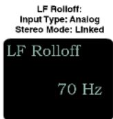
5) In Input menu, set LF Rolloff:
Low frequency audio content may be desirable or distracting, so the point at which the roll-off takes place can be set to 35, 50, 70, 100, 120 or 150 Hz.
LF Rolloff:
Input Type: Analog
Stereo Mode: Independent
5) Set output level (HP Volume p. 8).
6) Begin recording (p. 13).
Recording in Digital Mode
1) Connect microphone or audio source (p. 7).
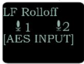
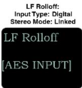
2) In Input menu, set Input Type to Digital:
When the Input Type is set to Digital, the two tricolor audio level indicator LEDs on the top of the SPDR will be blue for a signal above -40 and off otherwise. In Digital mode, the input is AES 3 compatible. In this configuration, pin 4 is + and pin 1 is -.
Input Level:
Input Type: Digital
Stereo Mode: Independent


6) In input matrix, set Steve Mada
4) In Input menu, set LF Rolloff:
Low frequency audio content may be desirable or distracting, so the point at which the roll-off takes place can be set to 35, 50, 70, 100, 120 or 150 Hz.
LF Rolloff:
Input Type: Digital
Stereo Mode: Independent
5) Set output level (HP Volume p. 8).
6) Begin recording (p. 13).
Browsing/Playing Back Recordings
Soft buttons in the Playback function provide the common button functions used for playback on a recording device. The soft buttons will change depending on the status of the playback: active playback, paused in the middle, or paused at the end.

Files/Play Choose to play files by the filename. File-names of the recordings contain industry standard iXML chunks in the file headers, with the most commonly used fields filled in. File naming can be set as:
- Sequence: a progressive sequence of numbers
- Clock Time: the time of the internal clock at the beginning of the recording; recorded as DDHHM-MA.WAV. DD is the day of the month, HH is hours, MM is minutes, A is the overwrite-prevention character, incrementing to 'B', 'C', etc. as needed to avoid a naming conflict A final character serves as the segment identifier, being absent in the first segment, '2' in the second segment, '3' in the third and so on.
- Scene/Take: the progressive scene and take automatically cataloged each time a recording is begun; S01T001.WAV. The initial 'S' is meant to suggest "Scene" but also serves as the overwrite prevention character, decrementing to 'R', 'O', etc. as needed to avoid a naming conflict. The "01" after the 'S' is the scene number. 'T' means take, and the "001" is the take number. An eighth character is used only for the second and subsequent (4 GB) segments for very large recordings. Scene numbers are entered manually. Take numbers increment automatically. (See Recording Screens.)
Takes/Play Choose to play the files based on scene and take. Scene and take numbers can be manually entered, and are embedded in the filenames and IXML headers of recordings. Take number automatically increments each time the record button is pressed. When browsing by scene and take, recordings that span multiple files are listed singly and played as one long recording. (See Recording Screens.)
SPDR
Copying Recordings to a Computer
- Remove your MicroSD card from the SPDR by lightly pushing down on the card and, when released, the card should pop out of the recorder enough to gently remove the card.
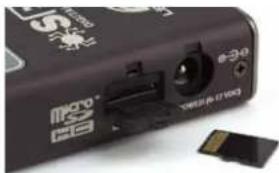
natural_image
Close-up of a black USB flash drive with a 34G port and a small SAG card (no visible text or symbols)- Insert the MicroSD card into the adapter.
- Slide the white button on the side of the adapter to the locked position and insert the adapter (with MicroSD card inside) into your computer's memory card slot.
NOTE: The MicroSD card adapter has a write protect tab. Sliding the tab downward to the locked position prevents recording of data and protects existing data. When recording to, erasing from or formatting the MicroSD card, slide the tab upward.
Write Protect Tab
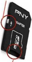
Insert MicroSD card into adapter here
- If using a Windows operating system, the computer should detect the card and assign it to a drive. Open the selected drive by clicking on the "Start" button and select "Computer" to launch Windows Explorer, the native file manager. Open the folder that was assigned to your MicroSD card.
Recovering an Interrupted Recording
Recordings can be reliably recovered even if the microSDHC memory card is accidentally removed or the battery dies while a recording is in progress. If a recording is interrupted, all of the audio is present on the card and can be easily recovered by the SPDR. The SPDR keeps track of the length of the most recent recording so it can supply a good suggestion for the length to recover. If the length is ever unknown or the SPDR's suggestion seems incorrect, it is always possible to override the suggested length. If in doubt, specify the maximum length possible, in which case the entire remainder of the card is recovered. All of the interrupted recording will be present, followed by extra contents which might be random noise or audio from previously deleted recordings.
NOTE: A good battery is required to begin the recovery process. If recovery is attempted with a weak battery, a message appears saying that a fresh battery will be required.
Once a fresh battery has been installed, power on the SPDR and insert the card with the interrupted recording. The SPDR will detect the interrupted recording and display:

And then:
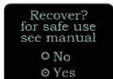
Once set as desired, use MENU/SEL to navigate to the "GO" soft button and press the DOWN arrow button to begin the recovery process.
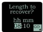
Recovery is nearly instantaneous. When completed, the display will show:

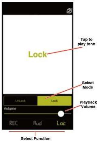
Locking and Unlocking the Settings
The LOCKED mode protects the recorder from accidental changes to its settings. When locked, menu navigation is possible, but any attempt to alter settings will prompt a "LOCKED/can use menu to unlock" message. The unit can be unlocked using the Lock/Unlock setup screen. The PDRRemote app will still work.
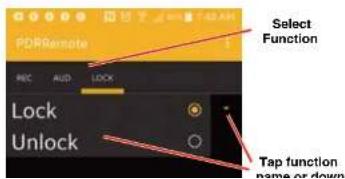
Using a Remote Control App
PDRRemote By New Endlan LLC
Convenient remote control is provided by a phone app available on the AppStore and Google Play. The app uses audio tones ("dweedle tones") played through the phone's speaker that are interpreted by the recorder to make changes:
- Record Start/Stop
iOS Version
Android Version
SPDR
5-Pin Input Jack Wiring
The wiring diagrams included in this section represent the basic wiring necessary for the most common types of microphones and other audio inputs. Some microphones may require extra jumpers or a slight variation on the diagrams shown.
It is virtually impossible to keep completely up to date on changes that other manufacturers make to their products, thus you may encounter a microphone that differs from these instructions. If this occurs please call our toll-free number listed under Service and Repair in this manual or visit our web site at:
www.lectrosonics.com

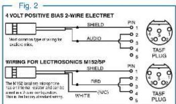
Audio input jack wiring:
PIN 1
Shield (ground) for positive biased electret lavaliere microphones. Shield (ground) for dynamic microphones and line level inputs.
PIN 2
Bias voltage source for positive biased electret lavaliere microphones that are not using servo bias circuitry and voltage source for 4 volt servo bias wiring.
PIN 3
Microphone level input and bias supply.
PIN 4
Bias voltage selector for Pin 3.
Pin 3 voltage depends on Pin 4 connection.
Pin 4 tied to Pin 1: 0 V
Pin 4 Open: 2 V
Pin 4 to Pin 2: 4 V
PIN 5
Line level input for tape decks, mixer outputs, musical instruments, etc.

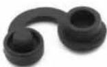
Note: If you use the dust boot, remove the rubber strain relief that is attached to the TA5F cap, or the boot will not fit over the assembly.
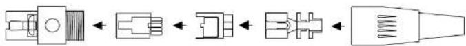
Microphone Cable Termination for Non-Lectrosonics Microphones
TA5F Connector Assembly
flowchart
graph LR
    A["Component 1"] --> B["↔"]
    B --> C["↔"]
    C --> D["↔"]
    D --> E["↔"]
Mic Cord Stripping Instructions
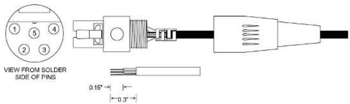
Crimping to Shield and Insulation

natural_image
Pure electrical circuit lines without any symbolsStrip and position the cable so that the clamp
SPDR
Input Jack Wiring for Different Sources
In addition to the microphone and line level wiring hook-ups illustrated below, Lectrosonics makes a number of cables and adapters for other situations such as connecting musical instruments (guitars, bass guitars, etc.) to the transmitter. Visit www.lectrosonics.com and click on Accessories, or download the master catalog.
A lot of information regarding microphone wiring is also available in the FAQ section of the web site at:
http://www.lectrosonics.com
Hover over Support and click on FAQs. Follow the instructions to search by model number or other search options.
Compatible Wiring for Both Servo Bias Inputs and Earlier Transmitters:
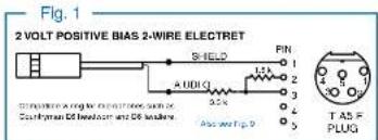


Simple Wiring - Can ONLY be used with Servo Bias Inputs:
Servo Bias was introduced in 2005 and all transmitters with 5-pin inputs have been built with this feature since 2007.
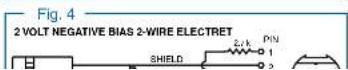

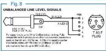
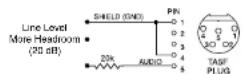
Line Level Signals
The normal wiring for line level signals is:
• Signal Hot to pin 5
- Signal Gnd to pin 1
- Pin 4 jumped to pin 1
This allows signal levels up to 3V RMS to be applied without limiting.
If more headroom is needed, insert a 20 k resistor in series with pin 5. Put this resistor inside the TA5F connector to minimize noise pickup.
See Fig. 8 on previous page
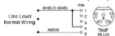
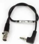
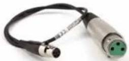
Wiring Diagram for MCAES3 Digital Cable
The MCAES3 cable is used to connect the output of the Lectrosonics SPDR portable recorder to the AES3 digital input of a mixer or recorder. It is constructed with a TA5F jack, rugged coaxial cable and a 3-pin female XLR connector. The connectors have soldered connections to the cable, allowing them to be serviced or replaced if the need arises.
Connectors: • 5-pin TA5F female
XLR-3 female
Cable: RG-174U coaxial
Length: 18 inches

SPDR
Optional Accessories
26526 Wire belt clip

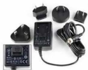
DCR12/A5U External power source; interchangeable blades.

natural_image
Product photo of a black electrical power adapter with attached circuit board and cable (no visible text or symbols)MC35 line level adapter cable. Female XLR to female TA5F; 37 inches long. Feed line level signal to pin 5 on the TA5M jack.
MC70 line level adapter cable. Male 3.5 mm TRS to female TA5F; 14 inches long. Feeds line level signal to pin 5 on the TA5M input jack.
MCAES3 Used to connect the output to the AES3 digital input of a mixer or recorder; TA5F jack to 3-pin female XLR connector
P1354 dust and moisture plug for headphone/line output and timecode sync port.
External Power Supply:
DCR12/A4U 90-240 VAC, 50/60 Hz input; 12 VDC (regulated), 400 mA max. output.

natural_image
Black electronic device with attached cable and connector (no visible text or symbols)External DC Power Cords:
21425 6 ft. long power cord, coaxial to stripped and tinned leads. Coaxial plug: ID-.080"; OD-.218"; Depth-.5".

21472 6 ft. long power cord; coaxial to stripped and tinned leads. Right angle coaxial plug: ID-.080"; OD-.215"; Depth-.400".

PS12A

PS12A Hirose 7-4 to sleeve
Specifications
Recording
Storage media: MicroSD (HC type)
File format: .wav files (BWF) iXML metadata
A/D converter: 24-bit
Sampling rate: 48 kHz or 96 kHz
Recording modes/Bit rate:
| Sample Rate | HD Stereo Mode Split | Gain Mode |
| 48 kHz 288 | kbps 576 kbps | |
| 96 kHz 576 | kbps not supported |
• Time Base: 1ppm TCXO
Input
Type: • Analog micrline level compatible; servo bias preamp for 2V and 4V lavaliere microphones
- Input 1 is switchable to AES3 two channel digital.
Input level: - Electret mic: Nominal 2 mV to 300 mV - Line level: 17 mV to 1.7 V - Dynamic mic: 0.5 mV to 50 mV
Input connector: TA5M 5-pin male
Headphone Output
Connector: 3.5 mm mini jack; TRS Maximum level: -3 dBu (575 mV RMS)
Audio Performance
Frequency response: 20 Hz to 20 kHz; +0.5/-1.5 dB Dynamic range: 110 dB (A), before limiting Distortion: < 0.035%
Time Code
Connector: 5-pin LEMO Signal voltage: 0.5V p-p to 5V p-p Input impedance: 10 k Ohms Format: SMPTE 12M - 1999 compliant
Battery Power/Life
Battery type: AA Lithium non-rechargeable
This device complies with part 15 of the FCC Rules. Operation is subject to the following two conditions: (1) This device may not cause harmful interference, and (2) this device must accept any interference received, including interference that may cause undesired operation.
NOTE: This equipment has been tested and found to comply with the limits for a Class B digital device, pursuant to part 15 of the FCC Rules. These limits are designed to provide reasonable protection against harmful interference in a residential installation. This equipment generates, uses and can radiate radio frequency energy and, if not installed and used in accordance with the instructions, may cause harmful interference to radio communications. However, there is no guarantee that interference will not occur in a particular installation. If this equipment does cause harmful interference to radio or television reception, which can be determined by turning the equipment off and on, the user is encouraged to try to correct the interference by one or more of the following measures:
— Reorient or relocate the receiving antenna.
— Increase the separation between the equipment and receiver.
— Connect the equipment into an outlet on a circuit different from that to which the receiver is connected.
— Consult the dealer or an experienced radio/TV technician for help.
Service and Repair
If your system malfunctions, you should attempt to correct or isolate the trouble before concluding that the equipment needs repair. Make sure you have followed the setup procedure and operating instructions. Check the interconnecting cables and then go through the Troubleshooting section in this manual.
We strongly recommend that you do not try to repair the equipment yourself and do not have the local repair shop attempt anything other than the simplest repair. If the repair is more complicated than a broken wire or loose connection, send the unit to the factory for repair and service. Don't attempt to adjust any controls inside the units. Once set at the factory, the various controls and trimmers do not drift with age or vibration and never require readjustment. There are no adjustments inside that will make a malfunctioning unit start working.
LECTROSONICS' Service Department is equipped and staffed to quickly repair your equipment. In warranty repairs are made at no charge in accordance with the terms of the warranty. Out-of-warranty repairs are charged at a modest flat rate plus parts and shipping. Since it takes almost as much time and effort to determine what is wrong as it does to make the repair, there is a charge for an exact quotation. We will be happy to quote approximate charges by phone for out-of-warranty repairs.
Returning Units for Repair
For timely service, please follow the steps below:
A. DO NOT return equipment to the factory for repair without first contacting us by email or by phone. We need to know the nature of the problem, the model number and the serial number of the equipment. We also need a phone number where you can be reached 8 A.M. to 4 P.M. (U.S. Mountain Standard Time).
B. After receiving your request, we will issue you a return authorization number (R.A.). This number will help speed your repair through our receiving and repair departments. The return authorization number must be clearly shown on the outside of the shipping container.
C. Pack the equipment carefully and ship to us, shipping costs prepaid. If necessary, we can provide you with the proper packing materials. UPS is usually the best way to ship the units. Heavy units should be "double-boxed" for safe transport.
D. We also strongly recommend that you insure the equipment, since we cannot be responsible for loss of or damage to equipment that you ship. Of course, we insure the equipment when we ship it back to you.
Lectrosonics USA:
Malling address: Shipping address: Telephone:
Lectrosonics, Inc. Lectrosonics, Inc. (505) 892-4501
PO Box 15900 581 Laser Rd. (800) 821-1121 Toll-free
Rio Rancho, NM 87174 Rio Rancho, NM 87124 (505) 892-6243 Fax
USA USA
LIMITED ONE YEAR WARRANTY
The equipment is warranted for one year from date of purchase against defects in materials or workmanship provided it was purchased from an authorized dealer. This warranty does not cover equipment which has been abused or damaged by careless handling or shipping. This warranty does not apply to used or demonstrator equipment.
Should any defect develop, Lectrosonics, Inc. will, at our option, repair or replace any defective parts without charge for either parts or labor. If Lectrosonics, Inc. cannot correct the defect in your equipment, it will be replaced at no charge with a similar new item. Lectrosonics, Inc. will pay for the cost of returning your equipment to you.
This warranty applies only to items returned to Lectrosonics, Inc. or an authorized dealer, shipping costs prepaid, within one year from the date of purchase.
This Limited Warranty is governed by the laws of the State of New Mexico. It states the entire liability of Lectrosonics Inc. and the entire remedy of the purchaser for any breach of warranty as outlined above. NEITHER LECTROSONICS, INC. NOR ANYONE INVOLVED IN THE PRODUCTION OR DELIVERY OF THE EQUIPMENT SHALL BE LIABLE FOR ANY INDIRECT, SPECIAL, PUNITIVE, CONSEQUENTIAL, OR INCIDENTAL DAMAGES ARISING OUT OF THE USE OR INABILITY TO USE THIS EQUIPMENT EVEN IF LECTROSONICS, INC. HAS BEEN ADVISED OF THE POSSIBILITY OF SUCH DAMAGES. IN NO EVENT SHALL THE LIABILITY OF LECTROSONICS, INC. EXCEED THE PURCHASE PRICE OF ANY DEFECTIVE EQUIPMENT.
This warranty gives you specific legal rights. You may have additional legal rights which vary from state to state.

- Table of Contents
- SPDR
- Introduction
- Technical Highlights
- Broadcast Wave Format
- iXML HEADER SUPPORT
- Timecode Support
- Dual Sample Rates
- Linked vs. Independent Stereo
- Split Gain Mode
- Dual Power Sources
- Power Options
- Battery Installation
- Power Input Connector
- Preparing a MicroSDHC Memory Card
- Compatible Cards
- Installing Card
- IMPORTANT
- Features and Controls
- Settings
- Powering On
- Powering Off
- Recording Screens
- Navigating Menus
- Main Menu and Sub Menus
- Timecode
- TC Jam (jam timecode)
- Frame Rate
- Use Clock
- Independent:
- LF Rolloff
- HP Volume
- Scene & Take
- SD Card
- Takes/Play
- File Naming
- About Card
- Record Mode
- Backlight
- Bat Type
- Remote
- About SPDR
- Default
- Operating Instructions
- Recording in Analog Mode
- Recording in Digital Mode
- 4) In Input menu, set LF Rolloff:
- Browsing/Playing Back Recordings
- Copying Recordings to a Computer
- Recovering an Interrupted Recording
- Locking and Unlocking the Settings
- Using a Remote Control App
- PDRRemote By New Endlan LLC
- 5-Pin Input Jack Wiring
- Audio input jack wiring:
- PIN 1
- PIN 2
- PIN 3
- PIN 4
- PIN 5
- Microphone Cable Termination for Non-Lectrosonics Microphones
- Input Jack Wiring for Different Sources
- http://www.lectrosonics.com
- Simple Wiring - Can ONLY be used with Servo Bias Inputs:
- Line Level Signals
- Wiring Diagram for MCAES3 Digital Cable
- Optional Accessories
- External Power Supply:
- External DC Power Cords:
- PS12A
- Specifications
- Recording
- Input
- Headphone Output
- Audio Performance
- Time Code
- Battery Power/Life
- Service and Repair
- Returning Units for Repair
- LIMITED ONE YEAR WARRANTY
Brand : Lectrosonics
Model : MCAES3
Category : Audio Equipment