O4FT1M - Security Camera Speco Technologies - Free user manual and instructions
Find the device manual for free O4FT1M Speco Technologies in PDF.

User questions about O4FT1M Speco Technologies
0 question about this device. Answer the ones you know or ask your own.
Ask a new question about this device
Download the instructions for your Security Camera in PDF format for free! Find your manual O4FT1M - Speco Technologies and take your electronic device back in hand. On this page are published all the documents necessary for the use of your device. O4FT1M by Speco Technologies.
USER MANUAL O4FT1M Speco Technologies
Important Safeguards and Warnings
1. Electrical safety
All installation and operation here should conform to local electrical safety codes.
Use a certified/listed 12VDC Class2 power supply only.
Please note: Do not connect two power supplying sources to the device at the same time; it may result in device damage! The
product must be grounded to reduce the risk of electric shock.
Improper handling and/or installation could run the risk of fire or electrical shock.
2. Environment
Heavy stress, violent vibration or exposure to water is not allowed during transportation, storage, and installation.
This product should be installed in a cool, dry place away from direct sunlight and heat sources.
Do not install the product in extreme temperature conditions.
Do not expose the camera to electromagnetic radiation. Otherwise, it may result in CMOS sensor failure.
Do not block any ventilation openings.
Do not allow water and liquid intrusion into the camera.
3. Operation and Daily Maintenance
Please shut down the device and then unplug the power cable before you begin any maintenance work.
Do not touch the CMOS sensor optic component. You can use a blower to clean the dust on the lens surface.
Always use the dry soft cloth to clean the device. If there is too much dust, use a cloth dampened with a small quantity of neutral
detergent. Finally use the dry cloth to clean the device.
Please use a professional optical cleaning method to clean the enclosure. Improper enclosure cleaning (such as using cloth) may result in poor IR functionality and/or IR reflection.
The grounding holes of the product are recommended to be grounded to further enhance the reliability of the camera.
Dome cover is an optical device, please do not touch or wipe cover surface directly during installation and use, please refer to the
Warning
This camera should be installed by qualified personnel only.
All the examination and repair work should be done by qualified personnel.
Any unauthorized changes or modifications could void the warranty.
Statement
This guide is for reference only.
Product, manuals, and specifications may be modified without prior notice. Speco Technologies reserves the right to modify these without notice and without incurring any obligation.
Speco Technologies is not liable for any loss caused by improper operation.
Regulatory Information
FCC conditions:
This device complies with part 15 of the FCC Rules. Operation is subject to the following two conditions:
● This device may not cause harmful interference.
● This device must accept any interference received, including interference that may cause undesired operation.
FCC compliance:
This equipment has been tested and found to comply with the limits for a digital device, pursuant to part 15 of the FCC Rules. These limits are designed to provide reasonable protection against harmful interference. This equipment generates uses and can radiate radio frequency energy and, if not installed and used in accordance with the instruction manual, may cause harmful interference to radio communication. However, there is no guarantee that interference will not occur in a particular installation. If this equipment does cause harmful interference to radio or television reception, which can be determined by turning the equipment off and on, the user is encouraged to try to correct the interference by one or more of the following measures:
● Reorient or relocate the receiving antenna.
- Increase the separation between the equipment and receiver.
- Connect the equipment into an outlet on a circuit different from that to which the receiver is connected.
Table of Contents
1 Introduction....2
2 Web Access and Login 3
3 Live View 5
4 Camera Configuration 7
4.1 System Configuration....7
4.1.1 System Information 7
4.1.2 Date and Time 7
4.1.3 Local Recording....8
4.1.4 Storage....8
4.2 Video Configuration....10
4.2.1 Image Configuration....10
4.2.2 Video / Audio Configuration....12
4.2.3 OSD Configuration 13
4.2.4 Video Mask 14
4.2.5 ROI Configuration 15
4.2.6 Zoom/Focus....15
4.3 Alarm Setup 16
4.3.1 Motion Detection 16
4.3.2 Other Alarms....17
4.3.3 Alarm In (Sensor Input)....19
4.3.4 Alarm Out 19
4.3.5 Alarm Server 20
4.4 Analytics Configuration....20
4.4.1 Exception 20
4.4.2 Line Crossing....21
4.4.3 Intrusion....23
4.4.4 Face Detection 25
4.4.5 Target Counting....27
4.7 Maintenance Configuration....40
4.7.1 Backup and Restore 40
4.7.2 Reboot 40
4.7.3 Upgrade 40
4.7.4 Operation Log 41
5 Search 42
5.1 Image Search 42
5.2 Video Search....44
5.2.1 Local Video Search 44
5.2.2 SD Card Video Search 45
Appendix 48
Appendix 1 Troubleshooting ....48
1 Introduction
Welcome
Thank you for purchasing this network camera!
Please read this manual carefully before operating the unit and retain it for further reference.
Should you require any technical assistance, please contact Speco Technologies Technical Support at 1-800-645-5516.
Main Features
● Built-in PoE (Power over Ethernet)
● Integrated IR LEDs for clear vision in low light
● IP67 rated for outdoor installations
● Remote viewing support via web browser, mobile APP, and CMS/VMS
Applications
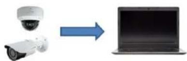
natural_image
Diagram showing a surveillance camera and a laptop connected by an arrow, no text or symbols present.IP Camera


Network
Web Browser

natural_image
Diagram showing a security camera icon transforming into a device (no text or symbols present)2 Web Access and Login
The IP camera settings can be accessed via a web browser through the LAN.
Available web browser: IE (plug-in required)/ Firefox/Edge/Safari/Google Chrome
It is recommended to use the latest version of these web browsers.
The menu display and operation of the camera may be slightly different by using the browser with plug-in or without plug-in. Installing plug-in will display more functions of the camera.
Connect IP-Cam via LAN or WAN. Here only take IE browser for example. The details are as follows:
- Access through IP Scanner
Network connection:

flowchart
graph LR
    A["IP Camera"] --> B["Router/Switch"]
    B --> C["Web Browser"]
①Make sure the PC and IP-Cam are connected on the same local network. The camera is set to DHCP by default and will be assigned an IP address by the DHCP server. Make sure that the local network has a DHCP server. Routers typically have a DHCP server built in.
② Install IP Scanner from the CD and run it after installation. IP Scanner is the tool for discovering the IP cameras on the local network.

text_image
SecureGuard IP Scanner Refresh Open Web Page Login... IP Restart Factory Default Information About Status Model Name Name IP Address MAC Address Wireless IP Address Zero Config IP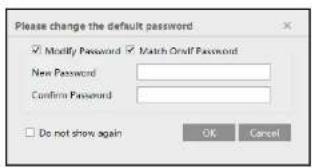
text_image
Please change the default password Modify Password Match Oralf Password New Password Confirm Password Do not show again OK CancelIf this is the first time for you to log in, the password prompt may only change the admin password. To change ONVIF password, you either have to check the "Match Onvif Password" box (if available) or go to the the ONVIF section to change the password. (Config→Network→Ports/Connections→Onvif)
text_image
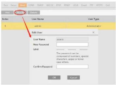
Add Modify Delete Index User Name User Type 1 admin Administrator Edit User User Name admin New Password Level The password can be composed of numbers, special characters, upper or lower case letters. Confirm Password OK Cancel3 Live View
The window below will be shown after logging in.
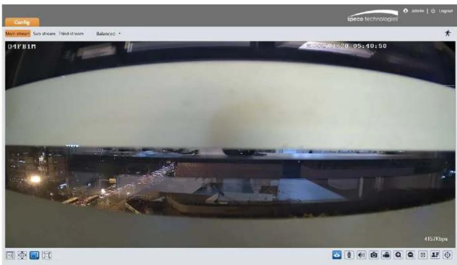
text_image
Config Main stream Sub stream Third stream Balanced D4FB1R 415/8bpsThe following table describes the icons on the live view interface
*Plug-in free live view: Two-way audio and local recording are not supported.
● All indicator icons above will flash in live view interface only when the corresponding events are enabled.
- In full screen mode, to exit, double click on the mouse or press the ESC key on the keyboard.
Click the zoom/focus control button to show the control panel. The descriptions of the control panel are as follows:
| Icon | Description | Icon | Description |
| Zoom - | Zoom + | ||
| Focus - | Focus + | ||
| One key focus (used when image is out of focus after manual adjustment) | |||
Face Capture View
① Go to Config→Event→Face Detection interface. Check "Enable".
② Return to the live view interface. Click 📄 to go to the following interface. When there are faces detected, the face pictures will be listed on the right.

text_image
Main stream Sub stream Third stream Balanced D4FB1M 2020/11/26 1m E3.5g ID4 锁 台 Mask Off 2020/11/26 1m E3.5g ID4 锁 台 Mask Off 2020/11/26 1m E3.5g4 Camera Configuration
Press the "Setup" button to go to the configuration interface.
Note: Wherever applicable, click the "Save" button to save the settings.
4.1 System Configuration
4.1.1 System Information
In the "System Information" Interface, the system information of the device is listed.
| Config Home ▶ System ▶ Basic Information | |
| Device Name | O4FB1M |
| Product Model | O4FB1M |
| Brand | Speco |
| Software Version | 5.1.1.0(27092) |
| Software Build Date | 2022-01-07 |
| Onvif Version | 21.06 |
| OCX Version | 2.2.0.3 |
| MAC | 5C:F2:07:d5:9a:3b |
| About this machine | Look Over |
4.1.2 Date and Time
To set the time and date, go to System→Date and Time. Please refer to the following interface.

text_image
Time Model: ● Synculatorize with NTP server NTP server: Time.windows.com Update period: 1440 Minutes ● Synculatorize with computer time Date: 2018-06-09 Time: 09:35:19 ● Set manually Date: 2018-06-09 Time: 09:35:19 Save4.1.3 Local Recording
Go to System→Local Recording to set up the storage path of captured pictures and recorded videos on the local PC. There is also an option to enable or disable the bitrate display in the recorded files.

text_image
Picture Path C:\Program Files\Speco\ADPCamera Record Path C:\Program Files\Speco\ADPCamera Video Audio Settings Open Close Show Bitrates Open Close Local Smart Snapshot Storage Open Close Rendering Mode High-efficient Mode(Recommended) Compatible Mode Low-efficient Mode(Not Recommended) SaveAdditionally, the snapshots triggered by smart events (including face detection, line crossing detection and intrusion detection) can be selected to save to the local PC.
Rendering Mode: High-efficient mode, compatible mode or low-efficient mode can be optional.
If the performance of your computer is not compatible with the web client or your computer has no graphics card, low-efficient mode is suggested.
4.1.4 Storage
Go to System→Storage to go to the interface as shown below.

- Go to Storage→Record to go to the interface as shown below.
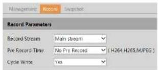
text_image
Management Record Snapshot Record Parameters Record Stream Main stream Pre Record Time No Pre Record (H264,H265,MJPEG) Cycle Write Yes- Set record stream, pre-record time and cycle writing.
Pre Record Time: Set the time to record before the actual recording begins.
- Set schedule recording. Check "Enable Schedule Record" and set the schedule.
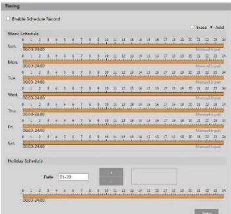
text_image
Timing Enable Schedule Record Wave Schedule Sun. 00:00-34:00 Mon. 00:00-24:00 Tue. 00:00-24:00 Wed. 00:00-24:00 Thu. 00:00-24:00 Fri. 00:00-24:00 Sat. 00:00-24:00 Holiday Schedule Date 01-20 Brasie Add Manual Input Manual Input Manual Input Manual Input Manual Input Manual Input Manual Input Manual Input Manual Input Manual Input Manual Input Manual Input Manual Input Manual Input Manual Input Manual Input Manual Input Manual Input Manual Input Manual Input Manual Input Manual Input Manual Input Manual Input Manual Input Manual Input Manual Input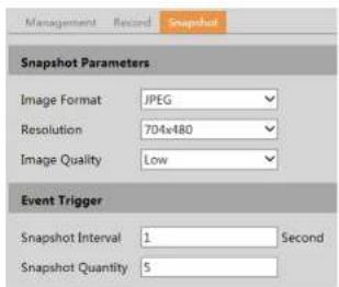
text_image
Management Record Snapshot Snapshot Parameters Image Format JPEG Resolution 704x480 Image Quality Low Event Trigger Snapshot Interval 1 Second Snapshot Quantity 5Set the format, resolution and quality of the image saved on the SD card and the snapshot interval and quantity and the timing snapshot here.
Snapshot Quantity: The number you set here is the maximum quantity of snapshots. The actual quantity of snapshots may be less than this number. Supposing the occurrence time of an alarm event is less than the time of capturing pictures, the actual quantity of snapshots is less than the set quantity of snapshots.
Timing Snapshot: Enable timing snapshot first and then set the snapshot interval and schedule. The setup steps of schedule are the same as the schedule recording (See Schedule Recording).
4.2 Video Configuration
Video Configuration includes Image Settings, Video/Audio Setup, OSD, Privacy Mask and Region of Interest.
4.2.1 Image Configuration
In the Image Settings interface as shown below, various settings can be adjusted, such as brightness, contrast, hue, and saturation and so on. The common mode and day and night mode can be set up separately. The image effect can be quickly viewed by switching the configuration file.
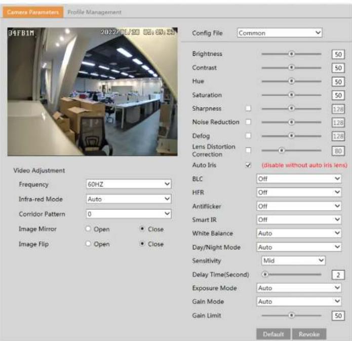
text_image
Camera Parameters Profile Management 04FB1M 2022/01/20 05:09:58 Config File Common Brightness 50 Contrast 50 Hue 50 Saturation 50 Sharpness 1.28 Noise Reduction 1.28 Defog 1.28 Lens Distortion 80 Correction Auto Iris (disable without auto iris lens) Video Adjustment Frequency 60HZ Infra-red Mode Auto Corridor Pattern 0 Image Mirror Open Close Image Flip Open Close BLC Off HFR Off Antiflicker Off Smart IR Off White Balance Auto Day/Night Mode Auto Sensitivity Mid Delay Time(Second) 2 Exposure Mode Auto Gain Mode Auto Gain Limit 50 Default RevokeBrightness: Set the brightness level of the camera's image.
Contrast: Set the color difference between the brightest and darkest parts.
can be set to 60 fps /50fps.
Antiflicker:
- Off: disables the anti-flicker function. This is used mostly in outdoor installations.
- 50Hz: reduces flicker in 50Hz lighting conditions.
- 60Hz: reduces flicker in 60Hz lighting conditions.
Smart IR: Choose "ON" or "OFF". This function can effectively avoid image overexposure so as to make the image more realistic. The higher the level is, the more overexposure compensation will be given.
White Balance: Adjust the color temperature according to the environment automatically.
Day/Night Mode: Choose "Auto", "Day", "Night" or "Timing".
Exposure Mode: Choose "Auto" or "Manual". If manual is chosen, the digital shutter speed can be adjusted.
Gain Mode: Choose "Auto" or "Manual". If "Auto" is selected, the gain value will be automatically adjusted according to the actual situation. If "Manual" is selected, the gain value shall be set manually. The higher the value is, the brighter the image is.
Frequency: 50Hz and 60Hz can be optional.
Infra-red Mode: Choose "Auto", "ON" or "OFF".
Corridor Pattern: Corridor viewing modes can be used for situations such as long hallways. 0, 90, 180 and 270 are available. The default value is 0. The video resolution should be 1080P or below if this function is used.
Image Mirror: Turn the current video image horizontally.
Image Flip: Turn the current video image vertically.
Schedule Settings of Image Parameters:
Click the "Profile Management" tab as shown below.

text_image
Camera Parameters Profile Management Schedule Full Time Config File Common SaveSet full time schedule for common, day or night mode and specified time schedule for day and night. Choose "Timing" in the drop-down box of schedule as shown below.

text_image
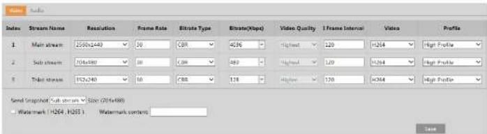
Stream Index Stream Name Resolution Frame Rate Eltrate Type Eltrate(Hop) Video Quality I Frame Interval Video Profile 1 Main stream 2500x240 30 CDR 4286 - Highest 120 H264 High Profile 2 Sub stream 704x491 30 CDR 480 - Highest 120 H264 High Profile 3 Ticket stream 152x240 30 CRR 178 - Highest 120 H264 High Profile Send Snapshot (Sub stream) Size (2014x490) Watermark (H264, H265) Watermark content: SaveThree video streams can be adjustable.
Resolution: The size of image.
Frame rate: The higher the frame rate, the video is smoother.
Bitrate type: CBR and VBR are optional. Bitrate is related to image quality. CBR means that no matter how much change is seen in the video scene, the compression bitrate will be kept constant. VBR means that the compression bitrate will be adjusted according to scene changes. For example, for scenes that do not have much movement, the bitrate will be kept at a lower value. This can help optimize the network bandwidth usage.
Bitrate: It can be adjusted when the mode is set to CBR. The higher the bitrate, the better the image quality will be.
Video Quality: It can be adjusted when the mode is set to VBR. The higher the image quality, the more bitrate will be required.
I Frame interval: It determines how many frames are allowed between a "group of pictures". When a new scene begins in a video, until that scene ends, the entire group of frames (or pictures) can be considered as a group of pictures. If there is not much movement in the scene, setting the value higher than the frame rate is fine, potentially resulting in less bandwidth usage. However, if the value is set too high, and there is a high frequency of movement in the video, there is a risk of frame skipping.
Video Compression: MJPEG, H264+, H264, H265or H265+can be optional. MJPEG is not available for main stream. If H.265/H.265+/H.265S is chosen, make sure the client system is able to decode H.265/H.265+. Compared to H.265, H.265+ saves more storage space with the same maximum bitrate in most scenes. Compared to H.264, H.265 reduces the transmission bitrate under the same resolution, frame rate and image quality.
Profile: For H.264. Baseline, main and high profiles are selectable.
Send Snapshot: Set the snapshot stream.
Video encode slice split: If this function is enabled, smooth image can be gotten even though using the low-performance PC.
Watermark: When playing back the local recorded video in the search Interface, the watermark can be displayed. To enable it, check the watermark box and enter the watermark text.
Click the "Audio" tab to go to the interface as shown below

text_image
Setup > Video > OSD Date Format YYYY-MM-DD Show Timestamp Device Name IPC Show Device Name OSD Content1 Add One Line OSD Content2 Add One Line OSD Content3 Add One Line OSD Content4 Add One Line SaveSet time stamp, device name, OSD content and picture overlap here. After enabling the corresponding display and entering the content, drag them to change their position. Then click the "Save" button to save the settings.
Picture Overlap Settings:
Check "OSD Content1", choose "Picture Overlay" and click "Browse" to select the overlap picture. Then click "Upload" to upload the overlap picture. The pixel of the image shall not exceed 200*200, or it cannot be uploaded.
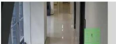
4.2.4 Video Mask
Go to Image→Video Mask interface as shown below. A maximum of 4 zones can be set up.
natural_image
Interior hallway with glass doors and a green carpet, no visible text or symbols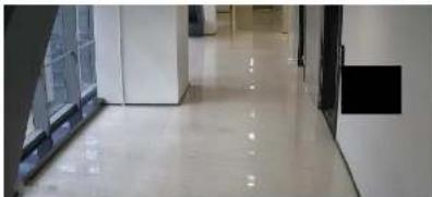
natural_image
Interior hallway with white tiled floor and glass railings, no visible text or symbolsTo clear the video mask:
Click the "Clear" button to delete the current video mask area.
4.2.5 ROI Configuration
Go to Image→ROI Config interface as shown below. An area in the image can be set as a region of interest. This area will have a higher bitrate than the rest of the image, resulting in better image quality for the identified area.

natural_image
Aerial view of a multi-lane road with cars and trees, no visible text or symbols.- Check "Enable" and then click the "Draw Area" button.
- Drag the mouse to set the ROI area.

text_image
04FB1M 2022/01/20 05:38:31 Day and night setting Focus One key focus Zoom - Zoom -1 Focus - Focus - Reset4.3 Alarm Setup
4.3.1 Motion Detection
Go to Alarm→Motion Detection to set motion detection alarm.
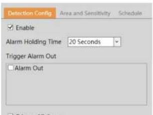
text_image
Detection Config Area and Sensitivity Schedule Enable Alarm Holding Time 20 Seconds Trigger Alarm Out Alarm OutTrigger FTP: If "Trigger FTP" and "Attach Picture" are checked, the captured pictures will be sent into FTP server address. Please refer to FTP configuration chapter for more details.
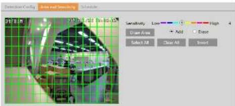
- Set motion detection area and sensitivity. Click the "Area and Sensitivity" tab to go to the interface as shown below.
text_image
Extrusion Coing Aire and Sensing Sensitivity Low High Close Area Add Close Select All Clear All InsertMove the "Sensitivity" scroll bar to set the sensitivity. Higher sensitivity value means that motion will be triggered more easily. Select "Add" and click "Draw". Drag the mouse to draw the motion detection area; Select "Erase" and drag the mouse to clear motion detection area. After that, click the "Save" to save the settings. "Clear All" can be used to clear out the entire motion zone.
- Set the schedule for motion detection. The schedule setup steps of the motion detection are the same as the schedule recording setup (See Schedule Recording).
4.3.2 Other Alarms
SD Card Full
- Go to Alarm→Anomaly→SD Card Full.

text_image
SD Card Full SD Card Error IP Address Collision Cable Disconnected Enable Alarm Holding Time 20 Seconds Trigger Alarm Out Alarm Out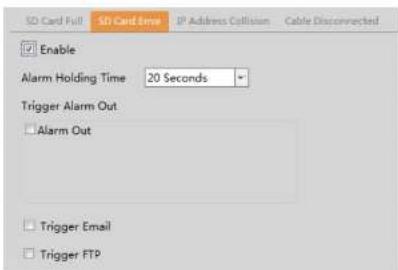
text_image
SD Card Full SD Card Error IP Address Collision Cable Disconnected Enable Alarm Holding Time 20 Seconds Trigger Alarm Out Alarm Out Trigger Email Trigger FTP- Click "Enable" and set the alarm holding time.
- Set alarm trigger options. Trigger alarm out, Email and FTP. The setup steps are the same as motion detection. Please refer to motion detection chapter for details.
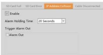
IP Address Conflict
This function is only available for the models with Alarm Out interface.
- Go to Alarm→Anomaly→IP Address Collision as shown below.
text_image
SD Card Full SD Card Error IP Address Collision Cable Disconnected Enable Alarm Holding Time: 20 Seconds Trigger Alarm Out Alarm Out- Click "Enable" and set the alarm holding time.
- Trigger alarm out. When the IP address of the camera conflicts with the IP address of other devices, the system will trigger the
4.3.3 Alarm In (Sensor Input)
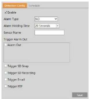
This function is only available for some models. To set sensor alarm (alarm in): Go to Alarm→Alarm In interface as shown below.
text_image
Detection Config Schedule Enable Alarm Type NO Alarm Holding Time 20 Seconds Sensor Name: Trigger Alarm Out Alarm Out Trigger SD Snap Trigger SD Recording Trigger Email Trigger FTP Save- Click "Enable" and set the alarm type, alarm holding time and sensor name.
- Set alarm trigger options. The setup steps are the same as motion detection. Please refer to motion detection chapter for details.
- Click "Save" button to save the settings.
- Set the schedule of the sensor alarm. The setup steps of the schedule are the same as the schedule recording setup. (See Schedule Recording).
4.3.4 Alarm Out
This function is only available for some models. Go to Alarm→Alarm Out.

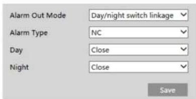
text_image
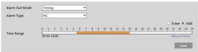
Alarm Out Mode Day/night switch linkage Alarm Type NC Day Close Night Close SaveTiming: Select the alarm type. Then click "Add" and drag the mouse on the timeline to set the schedule of alarm out; click "Erase" and drag the mouse on the timeline to erase the set time schedule. After this schedule is saved, the alarm out will be triggered in the specified time.
text_image
Alarm Out Mode Timing Alarm Type NC 0 1 2 3 4 5 6 7 8 9 10 11 12 13 14 15 16 17 18 19 20 21 22 23 24 Time Range 05:30-14:00 Erase Add Manual Input Save4.3.5 Alarm Server
Go to Alarm→Alarm Server interface as shown below.
Set the server address, port, heartbeat, and heartbeat interval. When an alarm occurs, the camera will transfer the alarm event to the alarm server. If an alarm server is not needed, there is no need to configure this section.

text_image
Server Address Port 8010 Heartbeat Disable Heartbeat interval 30 Second
text_image
Detection Config Sensitivity ✓Scene Change Detection ✓Video Blur Detection ✓Video Cast Detection Alarm Holding Time 20 Seconds Trigger Alarm Out ✓ Alarm Out ✓ Trigger SD Snap ✓ Trigger SD Recording ✓ Trigger Email ✓ Trigger FTP Save- Enable the applicable detection that is desired.
Scene Change Detection: Alarms will be triggered if the scene of the video has changed.
Video Blur Detection: Alarms will be triggered if the video becomes blurry.
Video Cast Detection: Alarms will be triggered if the image is abnormal caused by color deviation.
-
Set the alarm holding time and alarm trigger options. The setup steps are the same as motion detection. Please refer to motion detection chapter for details.
-
Click "Save" button to save the settings.
-
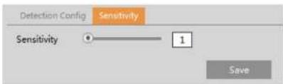
Set the sensitivity of the exception detection. Click "Sensitivity" tab to go to the interface as shown below.
text_image
Detection Config Sensitivity Sensitivity 1 Save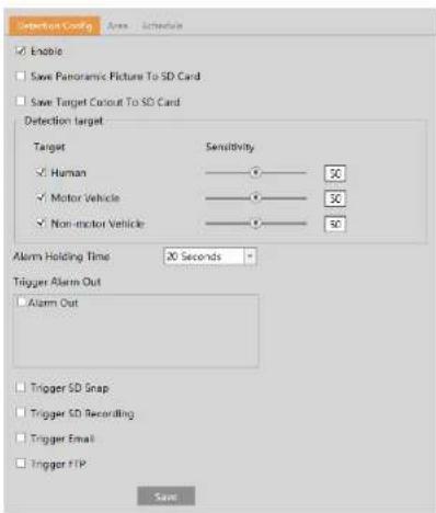
text_image
Detection Config Area Schedule Enable Save Panoramic Picture To SD Card Save Target Conout To SD Card Detection target Target Sensitivity Human 30 Motor Vehicle 30 Non-motor Vehicle 30 Alarm Holding Time 30 Seconds Trigger Alarm Out Alarm Out Trigger SD Snap Trigger SD Recording Trigger Email Trigger FTP Save- Enable line crossing alarm and select the snapshot type and the detection target.
Save Panoramic Picture: If it is enabled, the detected panoramic pictures will be captured and saved to the SD card when there are targets detected.
Save Target Cutout: If it is enabled, the detected target cutout pictures will be captured and saved to the SD card when there are targets detected.
Note: To save images to a local PC, please enable the local smart snapshot storage first (System→Local Recording). To save images to an SD card, please install an SD card first.
Detection Target:
Human: Select it and then alarms will be triggered if someone crosses the pre-defined alarm line.
Motor Vehicle: Select it and then alarms will be triggered if a vehicle with four or more wheels (eg. a car, bus or truck) crosses the pre-defined alarm line.
Non-motor Vehicle: Select it and then alarms will be triggered if a vehicle with two wheels (eg, a motorcycle or bicycle) crosses the

text_image
Detection Config Area Schedule Alarm: 1 Line Direction A->B Draw Area Clear SaveSet the alarm line number and direction. Up to 4 lines can be added. Multiple lines cannot be added simultaneously.
Direction: A<->B, A->B and A<-B optional. This indicates the direction of the intruder who crosses over the alarm line that would trigger the alarm.
A<->B: The alarm will be triggered when the intruder crosses over the alarm line from B to A or from A to B.
A->B: The alarm will be triggered when the intruder crosses over the alarm line from A to B.
A<-B: The alarm will be triggered when the intruder crosses over the alarm line from B to A.
Click the "Draw Area" button and then drag the mouse to draw a line in the image. Click the "Stop Draw" button to stop drawing. Click the "Clear" button to delete the lines. Click the "Save" button to save the settings.
- Set the schedule of the line crossing alarm. The setup steps of the schedule are the same as the schedule recording setup (See Schedule Recording).
※Configuration of camera and surrounding area
-
Auto-focusing function should not be enabled for line crossing detection.
-
Avoid the scenes with many trees or the scenes with various light changes (like many flashing headlights). The ambient brightness of the scenes shouldn't be too low.
-
Cameras should be mounted at a height of 10ft or above.
-
Keep the mounting angle of the camera at about 45°
-
The detected objects should not be less than 1% of the entire image and the largest sizes of the detected objects should not be more than 1/8 of the entire image.
-
Make sure cameras can view objects for at least 2 seconds in the detected area for accurate detection.

text_image
Detection Config Area Schedule Enable Save Panoramic Picture To SD Card Save Target Cutout To SD Card Detection target Target Sensitivity Human Motor Vehicle Non-motor Vehicle 50 50 50 Alarm Holding Time 20 Seconds Trigger Alarm Out Alarm Out Trigger SD Snap Trigger SD Recording Trigger Email Trigger FTP Save- Enable intrusion alarm and select the snapshot type and the detection target.
- Set the alarm holding time.
- Set alarm trigger options. The setup steps are the same as motion detection. Please refer to motion detection chapter for details.
- Click "Save" button to save the settings.
- Set the alarm area of the intrusion detection. Click the "Area" tab to go to the interface as shown below.
- Auto-focusing function should not be enabled for intrusion detection.
- Avoid the scenes with many trees or the scenes with various light changes (like many flashing headlights). The ambient brightness of the scenes shouldn't be too low.
- Cameras should be mounted at a height of 10ft or above.
- Keep the mounting angle of the camera at about 45°.
- The detected objects should not be less than 1% of the entire image and the largest sizes of the detected objects should not be more than 1/8 of the entire image.
- Make sure cameras can view objects for at least 2 seconds in the detected area for accurate detection.
- Adequate light and clear scenery are crucial to line crossing detection.
4.4.4 Face Detection
Face detection function is to detect the face appearing in the surveillance scene. Alarms will be triggered when a face is detected.
The setting steps are as follows:
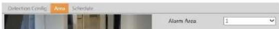
- Go to Event→Face Detection as shown below.
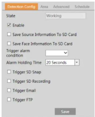
text_image
Detection Config Area Advanced Schedule State Working Enable Save Source Information To SD Card Save Face Information To SD Card Trigger alarm condition Alarm Holding Time 20 Seconds Trigger SD Snap Trigger SD Recording Trigger Email Trigger FTP Save
text_image
Detection Config Area Schedule Advanced 12/26/2018 1st Camera42 Draw Area Clear Min 3 % Max 50 % SaveUse this to draw the approximate size of the face that you want the camera to capture. This is useful when there are multiple faces in the background or foreground that are not needed to be captured. To enable, Click "Draw Area" and drag the border lines of the rectangle to modify its size. Move the rectangle to change its position. Click "Stop Draw" to stop drawing the area. Click "Clear" to clear the area. Then set the detectable face size by defining the maximum value and the minimum value(The default size range of a single face image occupies from 3% to 50% of the entire image).
-
Set the schedule of the face detection. The setup steps of the schedule are the same as schedule recording setup (See Schedule Recording).
-
Advanced configuration. Choose the snapshot interval and number as needed to avoid capturing multiple similar pictures in a very short period of time.

text_image
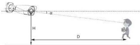
H D α- The object distance depends on the focal-length of the lens mounted in the camera.
- In order to guarantee the captured face recognition rate, the requirement for face capture are: left or right face turn angle is less than about 30^ ; pitching angle is less than 20^ .
- Face illumination must be uniform, if the brightness is low or there is a large area of shadow, need to do the light filling.
- When the capture scenario is backlight, the camera's BLC/HLC/WDR need to be turned on, or fill the light.
- The face recognition do not support black & white mode for now.
4.4.5 Target Counting
This function is to calculate the number of the people or vehicles crossing the alarm line through detecting, tracking and counting the shapes of the people or vehicles.
- Go to Config→Event→Target Counting as shown below.

text_image
Detection-Cating Area Schedule Enable Save Panoramic Picture To SD Card Save Target Cutout To SD Card Detection target Target Sensitivity Staying Threshold Human 50 0 Motor Vehicle 50 0 Non-motor Vehicle 50 0 Counting Reset Timing Off Manual Reset
text_image
Detection Config Area Schedule Entry: Humani# Car Bikes Exit: Humani# Car Bike Stay: Humani# Car Bike Alarm Line 1 Direction A->B Statistics OSD Entrance Entry Exit Exit Stay Stay Human human Car car Bike bike Under Welcome Threshold Over Please wait Threshold Draw Area Clear SaveSet the alarm line number and direction. Only one alarm line can be added.
Direction: A->B and A<-B can be optional. The direction of the arrow is entrance.
Statistics: If enabled, you can see the statistical information in the live view interface. If disabled, the statistical information will not be displayed in the live view interface.
The statistical OSD information can be customized as needed.
Click the "Draw Area" button and then drag the mouse to draw a line in the image. Check "Statistics" and then move the red box to change the position of the statistical information displayed on the screen. Click the "Stop Draw" button to stop drawing. Click the "Clear" button to delete the lines.
-
Set the schedule of the target counting. The setup steps of the schedule are the same as schedule recording setup (See Schedule Recording).
-
View the statistical information in the live view interface.


text_image
Target Location Report Type: Day Record Count Type: Count Time: 2022 - Year 1 Month 20 Buy Check Table Chart Index Count Time Human Motor Vehicle Non-motor Vehicle 1 2022-01-20 01:00:00 - 2022-01-20 00:59:59 0 0 0 2022-01-20 01:00:00 - 2022-01-20 01:59:59 0 0 3 2022-01-20 02:00:00 - 2022-01-20 02:59:59 0Select the report type. Daily report, weekly report, monthly report and annual report are selectable.
Select the count type. Enter or leave can be optional.
Select the start time and then click "Count". Then the counting result will display in the statistic result area. Click Table or Chart to display the result in different way.
4.5 Network Configuration
4.5.1 TCP/IP
Go to Network→TCP/IP interface as shown below. There are two ways for network connection.
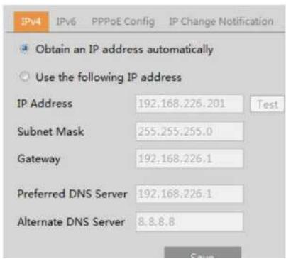
text_image
IPv4 IPv6 PPPoE Config IP Change Notification Obtain an IP address automatically Use the following IP address IP Address 192.168.226.201 Test Subnet Mask 255.255.255.0 Gateway 192.168.226.1 Preferred DNS Server 192.168.226.1 Alternate DNS Server 8.8.8.8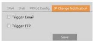
text_image
IPv4 IPv6 PPPoE Config IP Change Notification Trigger Email Trigger FTP SaveTrigger Email: when the IP address of the device is changed, the new IP address will be sent to the email address that has been set up.
Trigger FTP: when the IP address of the device is changed, the new IP address will be sent to FTP server that has been set up.
4.5.2 Port
Go to Network→Port interface as shown below. HTTP port, Data port and RTSP port can be set.

text_image
HTTP Port 80 HTTPS Port 443 Data Port 554 RTSP Port 9000 Persistent connection Port 8080 Enable Websocket Port 7681 SaveHTTP Port: The default HTTP port is 80. It can be changed to any port which is not occupied.
HTTPS Port: The default HTTPS port is 443. It can be changed to any port which is not occupied.
Data Port: The default data port is 9008. Please change it as necessary.
RTSP Port: The default port is 554. Please change it as necessary.
Persistent Connection Port: The port is used for a persistent connection of the third-party platform to push smart data, like face pictures.
WebSocket Port: Communication protocol port for plug-in free preview.
453 Server Configuration
4.5.4 Onvif
The camera can be searched and connected to the third-party platform via ONVIF/RTSP protocol.
text_image
Add User User Name: Password: Level: Custom Password: User Type: OK CancelNote: when adding the device to the third-party platform with ONVIF/RTSP protocol, please enter the username and password created in the above interface.
4.5.5 DDNS
If the camera is set up with a DHCP connection, DDNS should be set for accessing the camera from the internet. 1. Go to Network→DDNS.
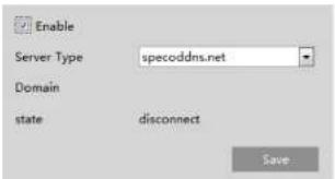
text_image
Enable Server Type specoddns.net Domain state disconnect Save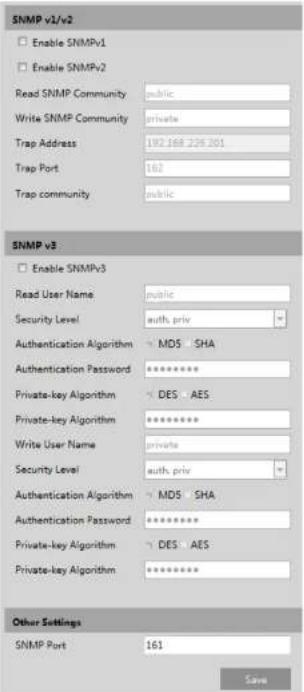
text_image
SNMP v1/v2 Enable SNMPv1 Enable SNMPv2 Read SNMP Community public Write SNMP Community private Trap Address 192.168.229.201 Trap Port 162 Trap community public SNMP v3 Enable SNMPv3 Read User Name public Security Level auth. priv Authentication Algorithm MDS SHA Authentication Password ********* Private-key Algorithm DES AES Private-key Algorithm ********* Write User Name private Security Level auth. priv Authentication Algorithm MDS SHA Authentication Password ********* Private-key Algorithm DES AES Private-key Algorithm ********* Other Settings SNMP Port 161 Save2 Check the corresponding version checkbox (Enable SNMPv1, Enable SNMPv2, Enable SNMPv3) according to the version of the
authentication system to identify the device in a local network. If the camera connected to the network interface of the switch has passed the authentication of the switch, it can be accessed via the local network.
Protocol type and EAPOL version: Please use the default settings.
User name and password: The user name and password must be the same with the user name and password applied for and registered in the authentication server.
4.5.8 RTSP
Go to Network→RTSP.

text_image
Enable Port 9008 Address http://P or domain naspport/profile1 http://P or domain naspport/profile2 http://P or domain naspport/profile3 Multicast address Main stream 236.0.0.0 50354 Automatic start Sub stream 239.0.0.1 51254 Automatic start Sub stream 230.0.0.2 52654 Automatic start Audio 236.0.0.3 53354 Automatic start Allow anonymous login (No username or password required)Select "Enable" to enable the RTSP function.
Port: Access port of the streaming media. The default number is 554.
RTSP Address: The RTSP address (unicast) format that can be used to play the stream in a media player.
Multicast Address
Main stream: The address format is
"rtsp://IP address: rtsp port/profile1?transportmode=mcast".
Sub stream: The address format is
"rtsp://IP address: rtsp port/profile2?transportmode=mcast".
Third stream: The address format is
"rtsp://IP address: rtsp port/profile3?transportmode=mcast".
Check "Enable", select stream type, set the reconnection time after timeout and server address as needed.
Server address: Enter the server address allocated by the third party server.
After that, click "Save" to save the settings. Then click "Refresh" to view the connection status.
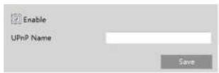
4.5.10 UPNP
If this function is enabled, the camera can be quickly accessed through the LAN.
Go to Network→UPnP. Enable UPNP and then enter UPnP name.
4.5.11 Email
If you need to trigger Email when an alarm happens or IP address is changed, please set the Email here first.
Go to Network→Email.
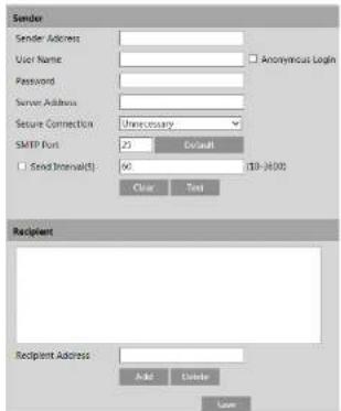
text_image
Sender Sender Address User Name: Anonymous Login Password: Server Address: Secure Connection: Unnecessary SMTP Port: 23 Default Send Internals() 66 10-4000 Clear Test Recipient Recipient Address: Add Delete Save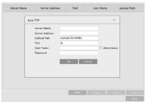
text_image
Server Name Server Address Port User Name Upload Path Acid FTP Server Name: Server Address: Upload Path Example/Div/folder Port 21 User Name: Password Anonymus OK Cancel Add Modify Satte ShowServer Name: The name of the FTP server.
Server Address: The IP address or domain name of the FTP.
Upload Path: The directory where files will be uploaded to.
Port: The port of the FTP server.
Use Name and Password: The username and password that are used to login to the FTP server.
4.5.13 HTTPS
HTTPS provides authentication of the web site and protects user privacy.
Go to Network→HTTPS as shown below.
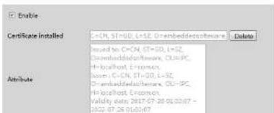
text_image
Enable Certificate installed C=CN, ST=GD, L=52, O=embeddedsoftware Delete used to C=CN, ST=GD, L=52, O=embeddedsoftware, CL=PC, H=localhost Efromon, base C=CN, ST=GD, L=52, O=embeddedsoftware, CL=PC, H=localhost Efromon, Validity data 2017-07-20 01:32:07 - 01:02.07.26 01:03:07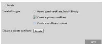
text_image
Enable Installation type Have signed certificate, install directly Create a private certificate Create a certificate request Create a private certificate Create SaveClick the "Create" button to create a private certificate. Enter the country (only two letters available), domain (camera's IP address/domain), validity date, password, province/state, region and so on. Then click "OK" to save the settings.
* Click "Create a certificate request" to enter the following interface.
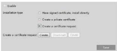
text_image
Enable Installation type Have signed certificate, install directly Create a private certificate Create a certificate request Create a certificate request Create Download Delete SaveClick "Create" to create the certificate request. Then download the certificate request and submit it to the trusted certificate authority for signature. After receiving the signed certificate, import the certificate to the device.
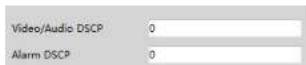
4.5.14 QoS
QoS (Quality of Service) function is used to provide different quality of services for different network applications. With the deficient bandwidth, the router or switch will sort the data streams and transfer them according to their priority to solve the network delay and network congestion by using this function.
Go to Network→QoS.

text_image
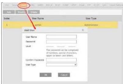
Setup > Security > User Admin Add Modify Delete Index User Name User Type Bind MAC 1 admin AdministratorAdd user:
- Click "Add" to pop up the following textbox.
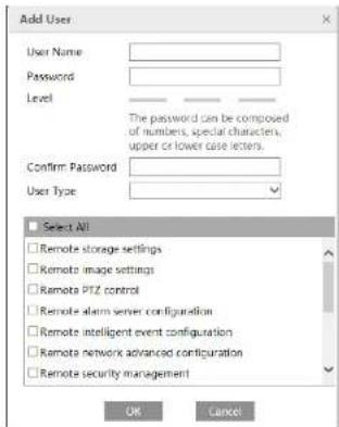
text_image
Add User User Name: Password: Level: The password can be composed of numbers, special characters, upper or lower case letters. Confirm Password: User Type: Select All Remote storage settings Remote image settings Remote PTZ control Remote alarm server configuration Remote intelligent event configuration Remote network advanced configuration Remote security management OK Cancel- Enter user name in "User Name" textbox.
- Enter letters or numbers in "Password" and "Confirm Password" textbox. Please set the password according to the requirement of
the password security level (Go to Setup→Security→Security Management→Password Security interface to set the security level). - Choose the user type and select the permission.
text_image
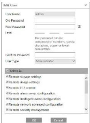
Edit User User Name admin Old Password New Password Level The password can be composed of members, special characters, upper or lower. Case letters. Confirm Password User Type Administrator Select All Remote storage settings Remote image settings Remote FTZ control Remote alarm server configuration Remote network event configuration Remote security management OK Cancel-
Enter the old password of the user in the "Old Password" text box.
-
Enter the new password in the "New password" and "Confirm Password" text box.
-
Modify the permission as necessary.
-
Click the "OK" button to save the settings.
Note: To change the access level of a user, the user must be deleted and added again with the new access level.
Delete user:
-
Select the user to be deleted in the user configuration list box.
-
Click the "Delete" button to delete the user.
Note: The default administrator account cannot be deleted.
4.6.2 Online User
Go to Security→Online User to view the user who is viewing the live video.
text_image
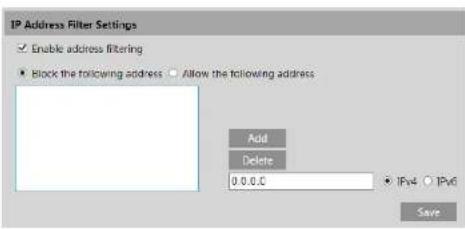
IP Address Filter Settings Enable address filtering Block the following address Allow the following address Add Delete 0.0.0.0 IPv4 IPv6 SaveThe setup steps are as follows:
Check the "Enable address filtering" check box.
Select "Block/Allow the following address", IPv4/IPv6 and then enter IP address in the address box and click the "Add" button.
4.6.4 Security Management
Go to Security→Security Management as shown below.
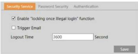
text_image
Security Service Password Security Authentication Enable "locking once illegal login" function Trigger Email Logout Time 3600 Second SaveIn order to prevent against malicious password unlocking, "locking once illegal login" function can be enabled here. If this function is enabled, login failure after trying six times will make the login interface locked. The camera can be logged in again after a half hour or after the camera reboots.
Trigger Email: if enabled, e-mail will be sent when logging in/out or illegal login lock occurs.
Logout time: Set the logout time as needed. For example: 3600s, you will be automatically logged out after 3600s and then you need to enter the username and password again to log in.
4.7 Maintenance Configuration
4.7.1 Backup and Restore
Go to Maintenance→Backup & Restore.

text_image
Import Setting Path Browse Import Setting Export Settings Export Settings Default Settings Keep Network Config Security Configuration Image Configuration Factory Default- Import & Export Settings
Configuration settings of the camera can be exported from a camera into another camera.
-
Click "Browse" to select the save path for import or export information on the PC.
-
Click the "Import Setting" or "Export Setting" button.
- Default Settings
Click the "Load Default" button to restore all system settings to the default factory settings except those you want to keep.
4.7.2 Reboot
Go to Maintenance→Reboot.
4.7.4 Operation Log
To query and export log:
- Go to Maintenance→Operation Log.
| Index | Time | Main Type | Sub Type | User Name | Logic IP |
| 1 | 2019-04-08 08:43:43 | Alarm | Motion start | ||
| 2 | 2019-04-08 08:43:24 | Alarm | Vfd Alarm | ||
| 3 | 2019-04-08 08:43:14 | Alarm | Motion stop | ||
| 4 | 2019-04-08 08:41:20 | Alarm | Motion start | ||
| 5 | 2019-04-08 08:40:26 | Alarm | Motion stop | ||
| 6 | 2019-04-08 08:40:08 | Alarm | Motion start | ||
| 7 | 2019-04-08 08:37:16 | Alarm | Motion stop | ||
| 8 | 2019-04-08 08:34:43 | Alarm | Motion start |
- Select the main type, sub type, start and end time.
- Click "Search" to view the operation log.
- Click "Export" to export the operation log.
5 Search
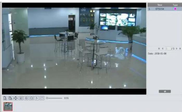
5.1 Image Search
In the Setup interface, click Search to go to the interface as shown below. Images that are saved on the PC or SD card can be found here.
text_image
Line Config Chart Record 0 CD Card Rev: Max Text Word The Art Set 1 2 3 4 5 6 7 8 9 10 11 12 13 14 15 16 17 18 19 20 21 22 23 24 25 26 27 28 29 36 37 38 39 40 41 46 47 48 49 50 51 56 57 58 59 60 60:00:00 - 20:00:00 Selected * 00:00:00 - 00:00:00 Select All Server Event Motion Detection Converse 241 254 264- Local Image Search
- Choose "Picture"—"Local".
- Set time: Select date and choose the start and end time.
- Click 🔒 to search the images.
- Double click a filename in the list to view the captured photos as shown above.
natural_image
Interior view of a modern office or meeting room with glass flooring, tables, chairs, and potted plants (no visible text or symbols)Click to return to the previous interface.
- SD Card Image Search
- Choose "Picture"—"SD Card".

text_image
ST Card Run Man Tue Wed Thu Fri Set 1 2 3 4 5 6 7 8 9 10 11 12 13 14 15 16 17 18 19 20 21 22 23 24 25 26 27 28 29 30 31 00:00:00 - 25:59:51| Icon | Description | Icon | Description |
| Close: Select an image and click this button to close the image. | Close all: Click this button to close all Images. | ||
| Save: Click this button to select the path for saving the image on the PC. | Save all: Click this button to select the path for saving all pictures on the PC. | ||
| Fit size: Click to fit the image on the screen. | Actual size: Click this button to display the actual size of the image. | ||
| Zoom in: Click this button to digitally zoom in. | Zoom out: Click this button to digitally zoom out. | ||
| Slide show play: Click this button to start the slide show mode. | Stop: Click this button to stop the slide show. | ||
| Play speed: Play speed of the slide show. | |||
5.2 Video Search
5.2.1 Local Video Search
Click Search to go to the interface as shown below. Videos were recorded locally to the PC can be played in this interface.

text_image
Record Local Sun Mon Tue Wed Thu Fri Sat 1 2 3 4 5 6 7 8 9 10 11 12 13 14 15 16 17 18 19 20 21 22 23 24 25 26 27 26 27 28 29 30 31 32 33 4 5 6 7 8 9 10 Time 00:00:00 - 23:55:59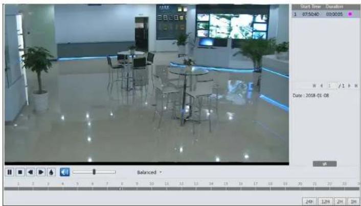
text_image
Start Time 1 07:50:40 09:00:05 Date : 2018-01-08 Balanced 24F 12H 2H 1H| Icon | Description | Icon | Description |
| Play button. After pausing the video, click this button to continue playing. | Pause button | ||
| Stop button | Speed down | ||
| Speed up | Watermark display | ||
| Enable / disable audio; drag the slider to adjust the volume after enabling audio. | |||
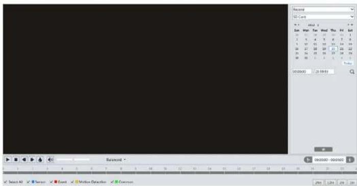
5.2.2 SD Card Video Search
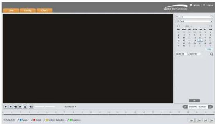
Click Search to go to the interface as shown below. Videos that were recorded on the SD card can be played in this interface.
text_image
Record 1D Card Sun Mon Tue Wed Thu Fri Sat 10 25 30 35 40 45 50 2 5 6 7 8 9 10 3 11 12 13 14 15 16 17 18 19 20 21 22 25 26 27 28 29 30 38 39 40 41 42 43 00:00:00 23:00:00 Balance - 12 00:00 - 00:00:00 Select All Event Motion Detection Concurs- Select the alarm events at the bottom of the interface.
- Select mix stream (video and audio stream) or video stream as needed.
- Double click on a file name in the list to start playback.

text_image
Mix Stream Visit Time Duration 1 07:31:51 00:12p7 2 05:30:15 02:00:32 3 05:27:17 00:02:49 4 05:21:35 00:05:19 5 05:18:25 00:02:58 6 05:14:53 00:03:21 7 05:08:17 00:06:09 8 04:53:15 00:14:48 9 04:50:24 00:02:41 10 04:49:26 00:05:49 Date : 2018-01-08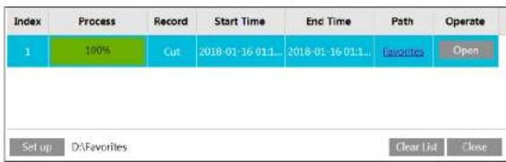
text_image
Index Process Record Start Time End Time Path Operate 1 100% Cut 2018-01-16 011... 2018-01-16 011... Favorites Open Set up D:\Favorites Clear List CloseClick "Set up" to set the storage directory of the video files.
Click "Open" to play the video.
Click "Clear List" to clear the downloading list.
Click "Close" to close the downloading window.
Appendix
Appendix 1 Troubleshooting
IP Scanner does not show any device.
Make sure that the PC that's running IP Scanner is on the same local network as the devices.
Internet Explorer cannot download ActiveX control.
IE browser may be set up to block ActiveX. Follow the steps below.
- Open IE browser and then click Tools→Internet Options.
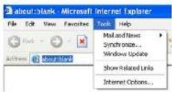
- Select Security→Custom Level.
- Enable all the options under "ActiveX controls and plug-ins".
- Click OK to finish setup.

text_image
Security Settings Settings ● Update ● Download signed active controls ○ Update ● Update ● Download signed active controls ○ Update ● Update ● Update and log Active controls not enabled as safe ○ Update ○ Update ● Update © 2017Models: O4FB1/O4FB1M/O4FD1/O4FD1M/O4FT1/O4FT1M
Federal Communications Commission (FCC) Statements
This device complies with Part 15 of the FCC Rules. Operation is subject to the following two conditions: (1) This device may not cause harmful interference, and (2) This device must accept any interference received, including interference that may cause undesired operation.
FCC Responsible Party:
Speco Technologies
200 New Highway
Amityville, NY11701
www.specotech.com