Intensifier O2IB50M - Security Camera Speco Technologies - Free user manual and instructions
Find the device manual for free Intensifier O2IB50M Speco Technologies in PDF.

User questions about Intensifier O2IB50M Speco Technologies
0 question about this device. Answer the ones you know or ask your own.
Ask a new question about this device
Download the instructions for your Security Camera in PDF format for free! Find your manual Intensifier O2IB50M - Speco Technologies and take your electronic device back in hand. On this page are published all the documents necessary for the use of your device. Intensifier O2IB50M by Speco Technologies.
USER MANUAL Intensifier O2IB50M Speco Technologies
IP Camera User Manual
O3FDP9 /O3FB56M /O3FB68 /O3FD8M O2iBD3 /O2iB68 / O2iB68M/ O2iD8 /O2iD8M O2B6M /O2iB50M /O2D6M /O2iD9 /O2iB9
IP Camera User Manual
Welcome
Thank you for purchasing this network camera!
This owner's manual is designed to be a reference tool for your system.
Please read this manual carefully before operating the unit and retain it for future reference.
Should you require any technical assistance, contact Speco Technologies Tech Support at 1-800-645-5516
Important Safeguards and Warnings
1. Electrical safety
All installation and operation here should conform to local electrical safety codes.
Use a certified/listed 12VDC Class 2 power supply only.
Please note: Do not connect two power supplying sources to the device at the same time; it may result in device damage! The product must be grounded to reduce the risk of electric shock.
Improper handling and/or installation could run the risk of fire or electrical shock.
2. Environment
Heavy stress, violent vibration or exposure to water is not allowed during transportation, storage and installation.
This product should be installed in a cool, dry place away from direct sunlight and heat sources.
Do not install the product in extreme temperature conditions.
Do not expose the camera to electromagnetic radiation. Otherwise it may result in CMOS sensor failure.
Do not block any ventilation openings.
Do not allow water and liquid intrusion into the camera.
- Operation and Daily Maintenance
Warning
This camera should be installed by qualified personnel only.
All the examination and repair work should be done by qualified personnel.
Any unauthorized changes or modifications could void the warranty.
Statement
This guide is for reference only.
Product, manuals and specifications may be modified without prior notice. Speco Technologies reserves the right to modify
these without notice and without incurring any obligation.
Speco Technologies is not liable for any loss caused by improper operation.
Note:
Before installation, check the package and make sure that all components are included.
Contact your rep or Speco customer service department immediately if something is broken or missing in the package.
| Accessory Name | Amount |
| Network Camera Unit | 1 |
| Junction Box | 1 |
| Quick Start Guide | 1 |
| Installation Accessories Bag | 1 |
| CD | 1 |
Table of Contents
Regulatory Information 2
- Introduction......6
Welcome 6
- Web Access and Login 7
2.1 LAN 7
-
Live View 8
-
Camera Configuration....9
4.1 System....9
4.1.1 System Restart....9
4.1.2 Factory Default....10
4.1.3 Export / Import 10
4.1.4 Date / Time 11
4.1.5 System Log....11
4.1.6 System Information....12
4.2 Basic Setup 13
4.2.1 Video Setup....13
4.2.2 Image Setup 14
4.2.3 Display....17
4.3 Network Setup 18
A 3.1 IP Address Column 1R
4.4.3 Alarm In Mode 23
4.4.4 Notification....24
4.5 User Admin....25
4.5.1 Password Change 25
4.5.2 User Account....25
Appendix 26
Appendix 1 Troubleshooting....26
IP Camera User Manual
1. Introduction
Thank you for purchasing this network camera!
Please read this manual carefully before operating the unit and retain it for future reference.
Should you require any technical assistance, please contact Speco Technologies Technical Support.
Applications
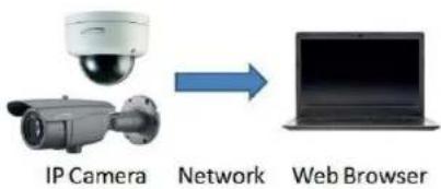
flowchart
graph LR
    A["IP Camera"] -->|Network| B["Web Browser"]
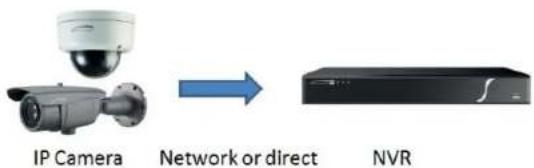
text_image
IP Camera Network or direct NVRIP Camera User Manual
2. Web Access and Login
The IP camera settings can be accessed via a web browser through the LAN.
2.1 LAN
- Access through IP Scanner
Network connection:
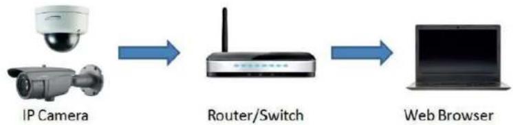
flowchart
graph LR
    A["IP Camera"] --> B["Router/Switch"]
    B --> C["Web Browser"]
① Make sure that the camera and the PC are connected on the same local network. The camera is set to DHCP by default and will be assigned an IP address by the DHCP server.
Make sure that the local network has a DHCP server. Routers typically have a DHCP server built in.
(2) Install IP Scanner from the CD and run it after installation. IP Scanner is the tool for discovering the IP cameras on the local network.
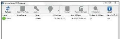
text_image
SecurityGuard 3D Server Network Open Web Page Logit... IP Server Report Server Details Information About Status ModuleName Name IP Server MAC Address Windows XP Server Tara Only 3D Enter Auto Auto Auto Auto Auto Auto Auto Auto Auto Auto Auto Auto Auto Auto Auto Auto Auto Auto Auto Auto Auto Auto Auto Auto Auto Auto Auto Auto Auto Auto Auto Auto Auto Auto Auto Auto Auto Auto Auto Auto Auto Auto Auto Auto Auto Auto Auto Auto Auto Auto 01/01/2019IP Camera User Manual
3. Live View
The window below will be shown after logging in.

text_image
Setup OFFSET H.264 10E STREAM Video size FIXED ORIGINAL Record Video START STOP SNAPSHOT Zoom + Zoom - Focus + Focus - Audio MIC SPAKER speco technologiesThe following table describes the buttons on the live view interface.
| Function | Button | Description |
| Stream | Dropdown menu | Choose which stream to view |
| Video Size | Fixed | Scales the video to fit in the browser window |
| Video Size | Original | Shows the video in the original resolution |
IP Camera User Manual
4. Camera Configuration
Press the "Setup" button to go to the configuration interface.
Note: Wherever applicable, press the "Save" button to save the settings.
4.1 System
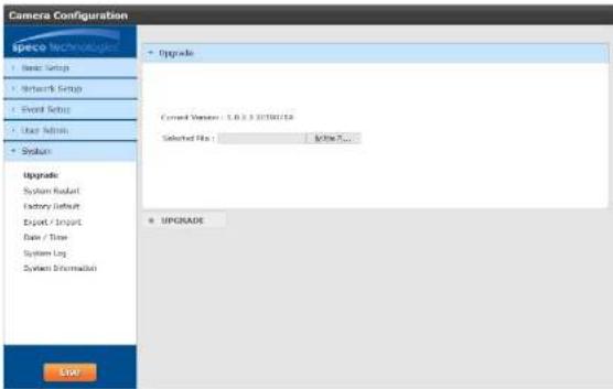
4.1.1 Upgrade
In the "System" interface, click on Upgrade to update the firmware of the device.
Navigate to the directory where the file is located and select it. Click on "Upgrade" at the bottom of the page to start the firmware update.
Make sure to not close the browser window until the update has completed. Firmware files can be downloaded on the Speco website.
text_image
Camera Configuration Speco Technologies Basic Setup Network Setup Event Setup User Admin System Upgrade System Readout Factory Default Export / Import Data / Time System Log System Information Upgrade Current Version: 1.0.3.32750/15 Selected Files: Active... UPGRADE START4.1.2 System Restart
IP Camera User Manual
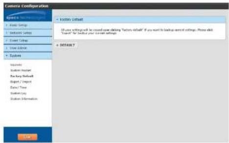
4.1.3 Factory Default
If the device needs to be factory reset for any reason, it can be done here. Be aware that this procedure will erase all settings that were changed and saved in the device and restore them to a factory default state. If restoring settings after a factory reset is desired, make sure to back up the settings using the "Export" function before the factory reset procedure.
text_image
Camera Configuration • Custom Default All user settings will be closed using clicking 'Custom Default' if you want to backup current settings. Please click "Custom" for default your current settings. + NOTABLE OK4.1.4 Export / Import
Export
Click the button to download the current system settings as a configuration file on the local PC.

text_image
Camera Configuration Special to Screen Help • Book Setup • Network Setup • Screen Setup • User Address • Systems • Export Make Setup File On Cash Options + Download/Export/Setup File • Export • ExportIP Camera User Manual
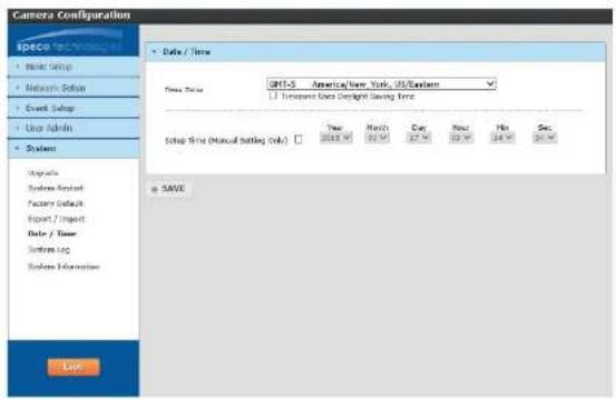
4.1.5 Date / Time
Time Zone
Select the appropriate time zone of the location of the device. The system time will update automatically if the device is connected to the internet.
Setup Time
If the device is not updating the time automatically for some reason, the time can be adjusted manually. Click the checkbox and change the time accordingly.
text_image
Camera Configuration SPACE TECHNOLOGY • Make Setup • Network Setup • Event Setup • Use Admin • System Setup Time (Manual Setting Only) Date / Time JPT-5 America/New York, US/Elemans J Tension Units Design Saving Time Setup Time (Manual Setting Only) Year 2018 Month 2017 Day Next 2016 No Sec Save © SAVE4.1.6 System Log
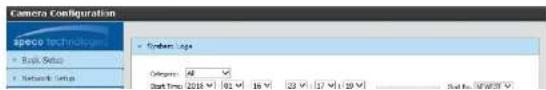
System log provides information on actions that were performed on the device such as providing the IP address of a PC that logged in to the device along with the date and time. Select the desired category to view and specify the start and end times to display the logs. Then click on "Search Logs" to retrieve the logs.
text_image
Camera Configuration speco technology Bank Sets Network Sets System Loga Parameters: 48 Start Time: 2018 102 16 V 23 V 17 V 129 V Start No: NFW59IP Camera User Manual
4.1.7 System Information
System Information
Provides information such as the current firmware version of the device and the model number. The device nickname can also be set up here. HTTP API Authentication and WSSE Authentication are used for 3rd party integration purposes and can remain disabled unless specifically needed.

text_image
Camera Configuration space technology Link Setup Network Setup Email Setup User Admins System Upgrade System Reset Factory Default Export / Export Date / Time System log System Information System Information Forward Version: 120.12.20270382 Pixel Type: constant Language: English ✓ FET-AR Authentication: Disable ✓ WISC Authentication: Disable ✓ Camera Manager: 0000464 Network Information SAVE LDONetwork Information
Provides network information of the device such as IP address and Mac address.

text_image
Camera Configuration Speed 100 MHz • Endo Setup • Network Setup • Point Setup • System Information • Network Information P Type: DHCP4.2 Basic Setup
Basic Setup includes setup for video, audio, and image settings.
4.2.1 Video Setup
Resolution, frame rate, etc. can be adjusted in this section. Each setting can be adjusted per stream. There are 3 streams in total – one main stream and two sub streams.

text_image
Camera Configuration Specio Technologies Basic Setup Video Setup Image Setup Display Main Stream Setting Code H.254 Resolution 350x15M Frame rate 30 G.O.F 80 Estimate mode CGR Struts Low Normal High E.O. Map Profile High Profile Curved View OFF Network Setup Event Setup User Admin System Bob Stream 1 Setting Bob Stream 2 Setting SAVECodec: For the main stream and sub stream 1, this is set to H.264. For sub stream 2, there is an option to choose between
H.264 and MJPEG.
Resolution: Set the desired resolution for each stream from the drop down list.
Frame Rate: Set the desired frame rate for each stream from the drop down list. Range is from 1 fps to 30 fps.
G.O.P: Stands for "Group of Pictures". This determines how many frames are processed in between unique I-frames. For example, if the frame rate is set to 30 fps and the GOP value is set to 1, there would be 30 I-frames per second. I-frames contain much more data compared to P-frames or B-frames. The higher the GOP value, the higher the image quality will be. For decoding process considerations, GOP should be set to a value equal to or greater than the frame rate.
Bitrate Mode: Choose between CBR (constant) or VBR (variable). The bit rate used in video encoding has a direct impact on the video quality and the bandwidth used to stream video over the network. As opposed to constant bit rate (CBR), VBR files vary the amount of output data per time segment VBR allows a higher bit rate (and therefore more storage space) to be allocated to the more complex segments of media files while
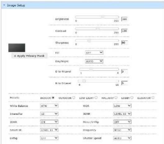
4.2.2 Image Setup
Image settings such as brightness, contrast, white balance, etc can be set up here.
- 2MP (O2iBD3 /O2iB68 / O2iB68M/ O2iD8 /O2iD8M /O2B6M /O2iB50M /O2D6M /O2iD9 /O2iB9)

text_image
Image Setup Brightness 0 255 161 Contrast 0 255 129 Sharpness 0 255 k6 Day/light AUTO D to N Level 1 0 3 N to D Level 4 11 5 Apply Privacy Mask FREETS INDIOR OUTDOOR LOW LIGHT HALLWAY LOBBY ELEVATOR White balance ATW WOR LOW Transistor x2 3DNR LEVEL 10 3DNR ON Mirror/V-Flip OFF Smart IR OFF Frequency INTSC Debug OFF Shutter Speed AUTO DC Lens Mode OUTDOORPrivacy Mask: There are 8 zones that can be applied. Right click within the image window and choose which zones to apply under "Show". Once the zones are enabled, they can be moved around within the image and resized. After adjustment, click "Apply Privacy Mask" to apply the changes. Brightness: Adjusts the brightness of the image. If set too high, it can have a white-out effect on the image. Contrast: Adjusts the contrast of the image which is the difference between black and white (color differentiation). If set too high, bright
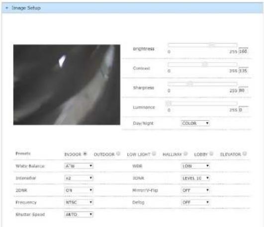
-2MP-F
text_image
Image Setup Brightness 0 259 160 Contrast 0 259 135 Sharpness 0 259 80 Luminance 0 259 0 Day/Night COLOR ▼ Presets INDOOR OUTDOOR LOW LIGHT HALLWAY LOBBY ELEVATOR White Balance A/W WDR LOW Interfer 42 3DAR LEVEL 10 2DAR ON Mirror/V-flip OFF Frequency NTSC Debug OFF Shutter Speed AMTOBrightness: Adjusts the brightness of the image. If set too high, it can have a white-out effect on the image.
Contrast: Adjusts the contrast of the image which is the difference between black and white (color differentiation). If set too high, bright scenes may look too bright.
Sharpness: Enhances edges for a sharper image perception. The higher the value, the less "soft" the image looks. However, if set too high,
this introduces artifacts in the video
Luminance: Reference brightness adjustment.
Day/Night: Can be set to Auto, Color, or Monochrome. If FIT mode is on, then this mode will be set to auto.
Presets: Presets adjust the WDR and Intensifier values automatically based the mode that's chosen. WDR and Intensifier can also be
adjusted manually.
White Balance: It adjusts color settings to achieve consistent quality in the white areas and other colors of the image.
Intensifier: Brighter video in low light
IP Camera User Manual
- 3MP (O3FDP9 /O3FB56M /O3FB68 /O3FD8M)
text_image
Image Setup Brightness 0 255 160 Contrast 0 255 130 Sharpness 0 255 80 Fill OFF Day/Night AUTO D to N Level 1 8 p N to D Level 4 11 s Controls INDOOR OUTDOOR LOW LIGHT HALLWAY LOBBY ELEVATOR White Balance ATW WDR LOW Intermittent >2 30%R LEVEL 10 20% R HIT/V-Hip OFF Smart OR LEVEL 11 Frequency MISC Unfog OFF Shutter speed AUTOPrivacy Mask: There are 8 zones that can be applied. Right click within the image window and choose which zones to apply under "Show". Once the zones are enabled, they can be moved around within the image and resized. After adjustment, click "Apply Privacy Mask" to apply the changes.
Brightness: Adjusts the brightness of the image. If set too high, it can have a white-out effect on the image.
Contrast: Adjusts the contrast of the image which is the difference between black and white (color differentiation). If set too high, bright scenes may look too bright.
Sharpness: Enhances edges for a sharper image perception. The higher the value, the less "soft" the image looks. However, if set too high, this introduces artifacts in the video.
FIT: FIT stands for Flexible Intensifier® Technology. Using Speco's low-light technology called Intensifier, the camera stays in color even in low light, to produce a quality color image. As light level drops even further, the camera will adjust itself automatically to provide the mode that will produce the best image according to the scene. The available modes are: color, monochrome without IR, and monochrome with IR.

IP Camera User Manual
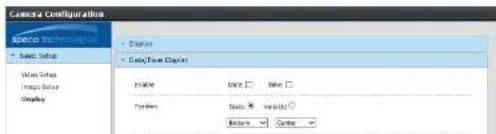
4.2.3 Display
Display
Enables an on-screen display on the video stream.
Position: Static places the OSD on a predefined area in the image. Variable allows for a user-specified location.
Size: Size of the font in the OSD.
Content Input: User-specified text. This can be used to display the nickname of the device.

text_image
Lemon's Configuration Display Preview Preview Size Text Color Background Color Color Transparency Level Data/Time Display SaveDate/Time Display
Enables an on-screen display of the date/time on the video stream.
Position: Static places the OSD on a predefined area in the image. Variable allows for a user-specified location.
Size: Size of the font in the OSD.
text_image
Camera Configuration Basic Setup Basic Setup Display Display Data/Time Display Enable OK Time Preview Status: Insulator: Options OrderIP Camera User Manual
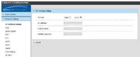
4.3 Network Setup
4.3.1 IP Address Setup
Sets the IP address, subnet mask, and gateway of the local network that the device is connected to. If the local network supports DHCP, the device can be set to DHCP mode and the network will assign an IP address to the device. The device is set to DHCP mode by default.
text_image
Camera Configuration SPICID IMOUNTED Basic System Network Settings IP Address Settings LNG GPG Cloud HIT FTP SMTP MSGP Fiat Setting IP Data IP Address Settings IP Type Member CACC IP/400000 Subnet Node Default Security = CACC4.3.2 DNS
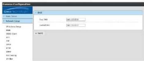
The DNS server addresses can be set up here. This does not have to be set up when using DHCP.
text_image
Camera Configuration E:\GPO\TNT100\B + Basic Status + Network Setup IP Active Group DIN HOLD Chart API FAT LSTM RTP LSTM FAT Setting PT Filter + GPIO Total: 268 SAP: 115.03.4 Connected: 1 SAP: 115.03.4 = SAVE4.3.3 DDNS Client
The device can be connected to Speco's DDNS server so that it can have a host name.
IP Camera User Manual
Click "Enable" to enable DDNS mode.
Enter a hostname for the device. The default name that's provided has the last 6 digits of the Mac address as part of the name.
If the name is found to be unique, it will be registered successfully on the DDNS server.
4.3.4 NTP
The device can configure the date and time automatically via an NTP (network time protocol) server if it is connected to the internet. The host name is "pool.ntp.org" by default. Other NTP servers can be entered manually. The Date / Time section under System Setup uses this NTP server to update the time when the time zone is selected.

text_image
Camera Configuration SPECO Technologies • Audio Setup • NATION STATUS IP Address Setup GND BOX: Cloud RTP FTP SMTP TCP SNP Port Setting IP Filter UP+P • Smart Setup • User Address • Systems NTP Settings Enable ○ Disable * Host Name: 100.482.000 Data Send: 1 - 24 bytes • SAVE Low4.3.5 FTP
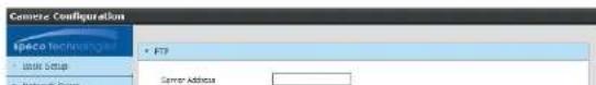
An FTP server can be used to store images for events. Enter the FTP server address, user ID, account password, and the port of the FTP server. Then enter the file name prefix and the file storage location on the server. For the file name, the date and time will be appended to the prefix.
text_image
Concrete Configuration File Name: Concrete • File Setup • Network Group • FTP Server AddressIP Camera User Manual
4.3.6 SMTP
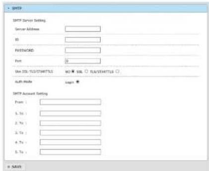
Emails can be sent with images when events occur. For the SMTP server setting, enter the information of the outgoing mail server. For common email services such as Gmail or Yahoo Mail, please check the SMTP settings for those services first and then enter them here. For SMTP Account Setting, enter the sender's email address and up to 5 emails addresses for the receiver.
text_image
SMTP SMTP Server Setting Server Address ID PASSWORD Port Use SQL/TLS/STARTLS NO SOL SQL/STARTLS Auth Mode Login * SMTP Account Setting From : 1. To : 2. To : 3. To : 4. To : 5. To : = SAVI4.3.7 RTSP
RTSP stands for Real Time Streaming Protocol and is used by various clients to stream the video from the device. Examples of clients are Speco's NVRs and SecureGuard® VMS. Other than changing the RTSP port (default is 554), the other options are advanced and do not need to be changed from the default settings for most applications.

text_image
Camera Configuration Space Basic Setup Network Setup IP Address Setup DNS DEM Chart FTP RTSP Port 354 Streaming Type Uncase Multicast Check Keep Active Enable EnableIP Camera User Manual
4.3.8 SNMP
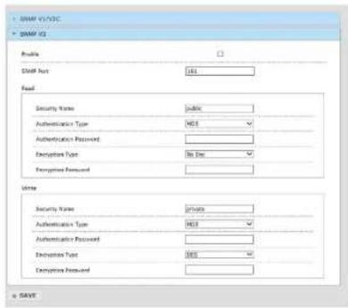
To get camera status, parameters and alarm information and remotely manage the camera, the SNMP function can be used.
Before using SNMP, please install an SNMP management tool and set the parameters of SNMP, such as SNMP port, trap address.
- Go to the SNMP section.
- Select the corresponding version (SNMPv1/SNMPv2c or SNMPv3) according to the version of the SNMP software that will be used.
- Set the values for "Read SNMP Community", "Write SNMP Community", "Trap Address", "Trap Port" and so on. Please make sure the settings are the same as that of the SNMP software.
text_image
DOSM V1/V2C DOSM V3 File DOSM Port 161 Read Security Name: public Authentication Type: MS Authentication Password: Encryption Type: No Data Encryption Password: Write Security Name: private Authentication Type: MS Authentication Password: Encryption Type: MS Encryption Password: + SAVE4.3.9 Port Setting
Set up the ports that are used to access different camera functions.
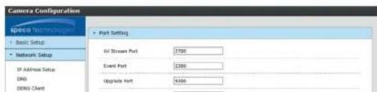
text_image
Camera Configuration Speed Technologies • Basic Setup • Network Setup IP Address Setup DNS DNS Client • Port Setting HV Stream Port 2700 Event Port 2300 Upgrade Port 9300IP Camera User Manual
4.3.10 IP Filter
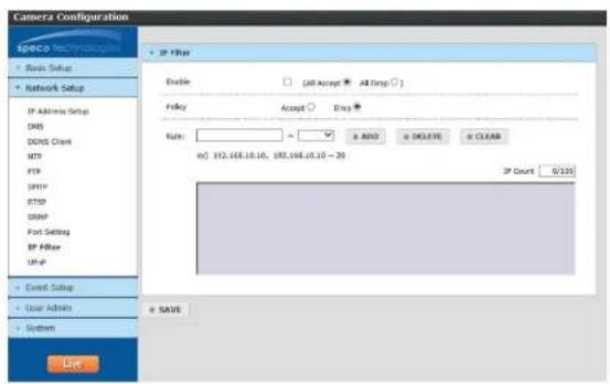
IP filtering can be used to provide access or deny access to a specific set of IP addresses.
- Select Enable and the select either "All Accept" or "All Drop".
- If All Drops is selected, then nobody can access the device except for a specified list of IP addresses and vice versa for All Accept.
- Specify the range of IP addresses under "Rule" and click Add to add the IP addresses to the list.
- Up to 100 IP addresses can be listed.
text_image
Camera Configuration SPRCP Technologies Basic Setup Network Setup IP Address Setup DNS DDNS Client MTP FTP SMTP SMTP DBMP Port Setting BP Filter Up-up Event Setup User Admin System Live Enable (All Accept ▼ All Drop □) Foley Accept □ Drag Rule: 82,168.10.10, 82,168.10.10 - 30 IP Count 0/220 + SAVE4.3.11 UPnP
If this function is enabled, the device will attempt to automatically open up ports on the local network and can be quickly accessed on the
The UPnP friendly name can be entered.

text_image
Camera Configuration SPGCG Network • Basic Setup • Network Setup IP Address Setup DNS • UWIP Port Forwarding Enable ○ Disable * Friendly Name: 237058-647009IP Camera User Manual
4.4 Event Setup
4.4.1 Motion Detection
Motion detection zone and sensitivity can be set up in this section.

text_image
Motion Detection Motion Sensitivity LOMINT Detection Area ( Drop a rectangular on the screen ) FULL AREA CLOSE ALL = SAVE- Set the sensitivity of motion detection for the zone. Higher sensitivity means that motion alarms will be triggered more easily.
- Click and drag the desired zone in the window. The defined zone will be highlighted.
4.4.2 Tampering Alarm
The device can detect tampering such as a global scene change and out of focus.
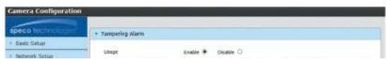
text_image
Camera Configuration speco Technology + Basic Setup + Network Setup + Tampering Alarm Usage Enable Disable ○IP Camera User Manual
4.4.3 Alarm in Mode
For devices with a sensor input, choose between Normally open or Normally closed.

text_image
Camera Configuration Camera Setup • Camera In Mode • Network Setup • Excel Setup Radio Deflection Alarm In Mode Applications • Use Options Systems • Add Direction (Start) Add Direction (End) • Add Options4.4.4 Notification
This section is used to control how notifications are delivered for motion and tampering alarm events.
Email: Choose the event type. Interval time defines how often the email is sent out. Images of the event can be attached to the email if enabled.

text_image
Camera Configuration SPECTR TECHNOLOGY • Start Image • Targeting • Start Image • Targeting • Start Image • Start Image • Targeting • Start Image • Targeting • Start Image • Targeting • Start Image • Targeting • Start Image • Targeting • Start Image • Targeting • Start Image • Targeting • Start Image • Targeting • Start Image • Targeting • Start Image • Targeting • Start Image • Targeting • Start Image • Targeting • Start Image • Targeting • Start image
IP Camera User Manual
4.5 User Admin
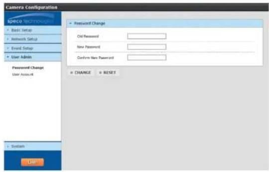
4.5.1 Password Change
Change the password of the admin account.
text_image
Camera Configuration Space Technology Basic Setup Network Setup Email Setup User Admin Password Change User Account System User Password Change Old Password New Password Confirm New Password CHANGE RESET4.5.2 User Account
Add or modify user accounts here.

text_image
Camera Configuration Apoico • Start Setup • Network Setup • Event Setup • User Admin • User Account 3D Password: COMPAR PAGEN/WORD • User AdminAppendix
Appendix 1 Troubleshooting
IP Scanner does not show any device.
Make sure that the PC that's running IP Scanner is on the same local network as the devices.
Internet Explorer cannot download ActiveX control
IE browser may be set up to block ActiveX. Follow the steps below.
1. Open IE browser and then click Tools->Internet Options

text_image
about-blank - Microsoft Internet Explorer File Edit View Favorites Tools Help Back Address about-blank Mail and News Synchronize... Windows Update Show Related Links Internet Options...- Select Security and then Custom Level.
- Enable all the options under "ActiveX controls and plug-ins".
- Click OK to finish setup.
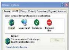
text_image
Internet Options General Security Price Content Connections Programs Advanced Select all sites categorized to specify in security settings Internet Local Internet Traded sites Particles Internet This is currently available to you Invent placed in other areas Source: http://www.ire.com