1215ROD - Fridge U-Line - Free user manual and instructions
Find the device manual for free 1215ROD U-Line in PDF.

User questions about 1215ROD U-Line
0 question about this device. Answer the ones you know or ask your own.
Ask a new question about this device
Download the instructions for your Fridge in PDF format for free! Find your manual 1215ROD - U-Line and take your electronic device back in hand. On this page are published all the documents necessary for the use of your device. 1215ROD by U-Line.
USER MANUAL 1215ROD U-Line
USER GUIDE & SERVICE MANUAL
SAFETY • INSTALLATION & INTEGRATION • OPERATING INSTRUCTIONS • MAINTENANCE • SERVICE

natural_image
Modern outdoor patio with stainless steel cooktop, open refrigerator, and large glass building under a canopy (no visible text or symbols)SAFETY • INSTALLATION & INTEGRATION • OPERATING INSTRUCTIONS • MAINTENANCE • SERVICE
Tip: Click on any section below to jump directly there
Contents
Intro
Safety
| Safety and Warning |
| Disposal and Recycling |
Installation
| Environmental Requirements |
| Electrical |
| Cutout Dimensions |
| Product Dimensions |
| Side by Side Installation |
| Anti-Tip Bracket |
| General Installation |
| Grille / Plinth Installation |
| Door Swing |
| Door Stop |
| Door Adjust |
Service
| Troubleshooting Warranty |
Service Extended
| Wire Diagram |
| Product Liability |
| Warranty Claims |
| Parts |
| Ordering Replacement Parts |
| System Diagnosis Guide |
| Compressor Specifications |
| Troubleshooting Extended |
| Control Quick Guide |
| Thermistor |
| Defrost |
WELCOME TO U-LINE
Congratulations on your U-Line purchase. Your product comes from a company with over five decades of premium modular ice making, refrigeration, and wine preservation experience. U-Line continues to be the American leader, delivering versatility and flexibility for multiple applications including residential, light commercial, outdoor and marine use. U-Line's complete product collection includes Wine Captain ^® Models, Beverage Centers, Clear Ice Machines, Crescent Ice Makers, Glass & Solid Door Refrigerators, Drawer Models, Freezers, Combo ^® Models, and more.
U-Line has captivated those with an appreciation for the finer things with exceptional functionality, style, inspired innovations and attention to even the smallest details. We are known and respected for our unwavering dedication to product design, quality and selection. U-Line is headquartered in Milwaukee, Wisconsin and has shipped product to five continents for over two decades and is proud to have the opportunity to ship to you.
PRODUCT INFORMATION
Looking for additional information on your product? User Guides, Spec Sheets, CAD Drawings, Compliance Documentation, and Product Warranty information are all available for reference and download at u-line.com.
PROPERTY DAMAGE / INJURY CONCERNS
In the unlikely event property damage or personal injury is suspected related to a U-Line product, please take the following steps:
- U-Line Customer Care must be contacted immediately at +1.800.779.2547.
- Service or repairs performed on the unit without prior written approval from U-Line is not permitted. If the unit has been altered or repaired in the field without prior written approval from U-Line, claims will not be eligible.
SAFETY · INSTALLATION & INTEGRATION · OPERATING INSTRUCTIONS · MAINTENANCE · SERVICE
Safety and Warning
NOTICE
Please read all instructions before installing, operating, or servicing the appliance.
Use this appliance for its intended purpose only and follow these general precautions with those listed throughout this guide:
SAFETY ALERT DEFINITIONS
Throughout this guide are safety items labeled with a Danger, Warning or Caution based on the risk type:
DANGER
Danger means that failure to follow this safety statement will result in severe personal injury or death.
WARNING
Warning means that failure to follow this safety statement could result in serious personal injury or death.
DANGER
This unit contains R600a (Isobutane) which is a flammable hydrocarbon. It is safe for regular use. Do not use sharp objects to expedite defrosting. Do not service without consulting the "R600a specifications" section included in the User Guide. Do not damage the refrigerant circuit.
WARNING
Service must be done by factory authorized service personnel. Any parts shall be replaced with like components. Failure to comply could increase the risk of possible ignition due to incorrect parts or improper service.
SAFETY • INSTALLATION & INTEGRATION • OPERATING INSTRUCTIONS • MAINTENANCE • SERVICE
Disposal and Recycling

DANGER
RISK OF CHILD ENTRAPMENT. Before you throw away your old refrigerator or freezer, take off the doors and leave shelves in place so children may not easily climb inside.
If the unit is being removed from service for disposal, check and obey all federal, state and local regulations regarding the disposal and recycling of refrigeration appliances, and follow these steps completely:
- Remove all consumable contents from the unit.
- Unplug the electrical cord from its socket.
- Remove the door(s)/drawer(s).
SAFETY • INSTALLATION & INTEGRATION • OPERATING INSTRUCTIONS • MAINTENANCE • SERVICE
Environmental Requirements
This unit is designed to operate between 50^ F ( 10^ C) and 100^ F ( 38^ C). Higher ambient temperatures may reduce the unit's ability to reach low temperatures and/or reduce ice production on applicable models.
For best performance, keep the unit out of direct sunlight and away from heat generating equipment.
In climates where high humidity and dew points are present, condensation may appear on outside surfaces. This is considered normal. The condensation will evaporate when the humidity drops.
CAUTION
Damages caused by ambient temperatures of 40^ F ( 4^ C) or below are not covered by the warranty.
SAFETY • INSTALLATION & INTEGRATION • OPERATING INSTRUCTIONS • MAINTENANCE • SERVICE
Electrical
WARNING
SHOCK HAZARD — Electrical Grounding Required. Never attempt to repair or perform maintenance on the unit until the electricity has been disconnected.
Never remove the round grounding prong from the plug and never use a two-prong grounding adapter.
Altering, cutting or removing power cord, removing power plug, or direct wiring can cause serious injury, fire, loss of property and/or life, and will void the warranty.
Never use an extension cord to connect power to the unit.
Always keep your working area dry.
NOTICE
Electrical installation must observe all state and local codes. This unit requires connection to a
SAFETY • INSTALLATION & INTEGRATION • OPERATING INSTRUCTIONS • MAINTENANCE • SERVICE
Cutout Dimensions
PREPARE SITE
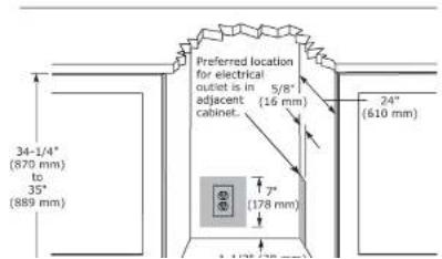
Your U-Line product has been designed for either freestanding or built-in installation. When built-in, your unit does not require additional air space for top, sides, or rear. However, the front grille must NOT be obstructed, and clearance is required for an electrical connection in the rear.
CAUTION
Unit can NOT be installed behind a closed cabinet door.
CUTOUT DIMENSIONS
text_image
Preferred location for electrical outlet is in 5/8" adjacent cabinet. (16 mm) 24" (610 mm) 34-1/4" (870 mm) to 35" (889 mm) 7" (178 mm)SAFETY • INSTALLATION & INTEGRATION • OPERATING INSTRUCTIONS • MAINTENANCE • SERVICE
Product Dimensions

text_image
Not Including Handle 23-1/4" (591 mm) 34-1/8" to 35-1/8" (867 mm to 892 mm)SAFETY • INSTALLATION & INTEGRATION • OPERATING INSTRUCTIONS • MAINTENANCE • SERVICE
Side-by-Side Installation
Two units may be installed side-by-side.
Cutout width for a side-by-side installation is the cutout dimension of a single unit times two.
No trim kit is required. However, 1/4" (6 mm) of space needs to be maintained between the units to ensure unobstructed door swing.
Units must operate from separate, properly grounded electrical receptacles placed according to each unit's electrical specifications requirements.
-
Place bracket over holes and attach to unit with two screws removed in step 2 using a T-25 Torx driver. Tighten screws fully.
-
Gently push units into position. Be careful not to entangle the electrical cord or water line, if applicable.
-
Re-check the leveling, from front to back and side to side. Make any necessary adjustments. The unit's top surface should be approximately 1/8" (3 mm) below the countertop.
Side-by-Side Installation with Bracket
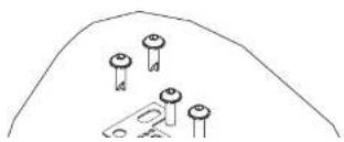
- Slide both units out so screws on top of units are easily accessible.
- Remove screws as shown below.
natural_image
Simple line drawing of a mountain peak with four small pins and a bracket (no text or symbols)SAFETY • INSTALLATION & INTEGRATION • OPERATING INSTRUCTIONS • MAINTENANCE • SERVICE
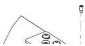
Anti-Tip Bracket
- Slide unit out so screws on top of unit are easily accessible.
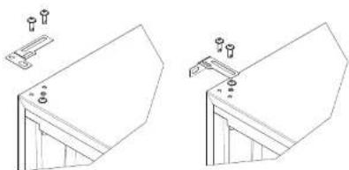
- Remove the two screws from the opposite side of the hinge assembly using a T-25 Torx driver (see below).
NOTE: 1224 models shown with four screw. 1215 models only have three screws, but same screws are used in both applications.
natural_image
Technical line drawing of two mechanical bracket assemblies with mounting holes and fasteners (no text or symbols)- Place bracket (part #14154) over holes and attach to unit with two screws removed in step 2 using a T-25 Torx driver. Tighten screws fully.
- Gently push unit into position. Be careful not to entangle the electrical cord or water line, if applicable.
SAFETY • INSTALLATION & INTEGRATION • OPERATING INSTRUCTIONS • MAINTENANCE • SERVICE
General Installation
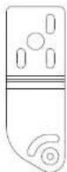
LEVELING INFORMATION
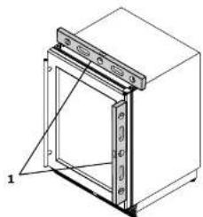
- Use a level to confirm the unit is level. Level should be placed along top edge and side edge as shown.
natural_image
Technical line drawing of a cabinet or enclosure with a door and side panel, no text or symbols present- If the unit is not level, adjust the legs on the corners of the unit as necessary.
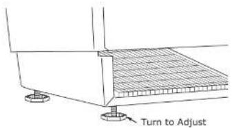
text_image
Turn to Adjust- Confirm the unit is level after each adjustment and repeat the previous steps until the unit is level.
INSTALLATION
- Plug in the power/electrical cord.
- Gently push the unit into position. Be careful not to entangle the cord.
- Re-check the leveling, from front to back and side to side. Make any necessary adjustments. The unit's top surface should be approximately 1/8" (3 mm) below the countertop.
- Remove the interior packing material and wipe out the inside of the unit with a clean, water-dampened cloth.
SAFETY • INSTALLATION & INTEGRATION • OPERATING INSTRUCTIONS • MAINTENANCE • SERVICE
Grille - Plinth Installation
REMOVING AND INSTALLING GRILLE
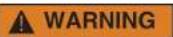
Disconnect electric power to the unit before removing the grille.
When using the unit, the grille (plinth strip/base fascia) must be installed.

DO NOT touch the condenser fins (4). The condenser fins are SHARP and can be easily damaged.
text_image
Technical diagram of a front-mounted air conditioner unit with numbered components labeled 1 through 5Removing the grille
- Disconnect power to the unit.
- Loosen the two screws (1).
- Remove grille (2) and grille cap (3) from unit.
Installing the grille
SAFETY • INSTALLATION & INTEGRATION • OPERATING INSTRUCTIONS • MAINTENANCE • SERVICE
Door Swing
text_image
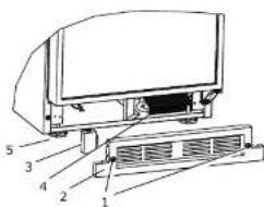
Wall 1/4" Min. (6 mm) 90 Door Swing Wall 2-1/8" Min. (54 mm) 90 Door SwingUnits have a zero clearance for the door to open 90°, when installed adjacent to cabinets.
Stainless Steel and black and white models require 2-1/8" (54 mm) door clearance to accommodate the handle if installed next to a wall.
Integrated models require 1/4" (6 mm) clearance if installed next to a wall. Allow for additional space for any knobs or pulls installed on the integrated panel/frame.
SAFETY • INSTALLATION & INTEGRATION • OPERATING INSTRUCTIONS • MAINTENANCE • SERVICE
Door Stop
Your U-Line unit was shipped to you with the optional 90° pin(s). (Models that are 15" wide include 1 pin. Models that are 24" wide include 2 pins.) The unit's door will open freely without a fixed opening angle limitation. If you would like the door stop at 90° follow these instructions.
NOTICE
The pin is designed to stop the door at 90^ under normal operating conditions. It is not designed for excessive force. Do not use the door to move the unit in/out of the cutout during installation.
If your unit is already undercounter, it might need to be moved out/forward to access the hinge.
- Locate the threaded pin.
- With the door between 0° (closed) and 90° and using a 3/32" hex driver, install the threaded pin through the hinge.
- On 24" models, a second pin is included for the bottom hinge. Repeat steps above for second hinge.
NOTE: Threaded pin will be inserted from the bottom.

natural_image
Technical line drawing of a mechanical assembly with no visible text or symbols- Carefully slide your unit back in place.
NOTICE
The pin can be removed to return the door swing back to its original state by unscrewing the threaded pin.
SAFETY • INSTALLATION & INTEGRATION • OPERATING INSTRUCTIONS • MAINTENANCE • SERVICE
Door Adjustments
DOOR ALIGNMENT AND ADJUSTMENT
Align and adjust the door if it is not level or is not sealing properly. If the door is not sealed, the unit may not cool properly, or excessive frost may form in the interior.
NOTICE
Properly aligned, the door's gasket should be firmly in contact with the cabinet all the way around the door (no gaps). Carefully examine the door's gasket to ensure that it is firmly in contact with the cabinet. Also make sure the door gasket is not pinched on the hinge side of the door.
To align and adjust the door:
- Loosen (do not remove) top and bottom hinge screws.
- Align door squarely with cabinet.
- Make sure gasket is firmly in contact with cabinet all the way around the door (no gaps).
- Tighten bottom hinge screws.

TO REVERSE THE DOOR
Remove grille:
Remove the grille (see GRILLE-PLINTH INSTALLATION section of this guide).
Remove top hinge and door:
- Hold door to keep it from falling.
- Remove top hinge from cabinet by removing three screws. Set aside and save for possible future use.
SAFETY • INSTALLATION & INTEGRATION • OPERATING INSTRUCTIONS • MAINTENANCE • SERVICE
- Remove door by tilting forward and lifting door off bottom hinge. Retain shoulder washers; they will be reused.
- Remove three screws from hinge holes on the opposite side. Reinstall into holes where the hinge was removed. Take care not to scratch cabinet.
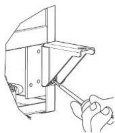
Remove bottom hinge:
- Remove bottom hinge from cabinet.
natural_image
Line drawing of a hand using a tool to adjust or install a mechanical component (no text or symbols present)-
Remove corresponding screws on opposite side of cabinet. On some models there may be a nut behind one or both screws on either side.
-
Remove magnet assembly from door with T-10 TORX driver. Be sure to only remove the two screws holding the assembly to the door. Reinstall on the opposite end of the door
- Rotate gasket 180°, aligning notch with magnet assembly and pressing firmly into the gasket channel starting at the corners.
- Rotate door 180° to reverse.
Install top hinge and door:
- Use alternate hinge supplied with unit and reinstall the screws. Do not tighten...

- Lift the door on to the bottom hinge.
- Align flat edge of the hinge with the outer edge of the
To-tall battery bins
SAFETY • INSTALLATION & INTEGRATION • OPERATING INSTRUCTIONS • MAINTENANCE • SERVICE
First Use
All U-Line controls are preset at the factory. Initial startup requires no adjustments.
NOTICE
U-Line recommends allowing the unit to run overnight before loading with product. As warm air rises, the temperature inside the unit tends to be slightly warmer at the top and slightly cooler at the bottom.
When plugged in, the unit will begin operating under the factory default settings. If the unit was turned off during installation, simply press ⏻ and the unit will immediately switch on. To turn the unit off, press ⏻.
SAFETY • INSTALLATION & INTEGRATION • OPERATING INSTRUCTIONS • MAINTENANCE • SERVICE
Control Operation
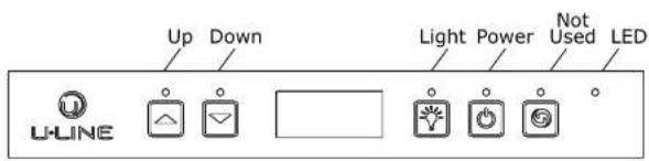
text_image
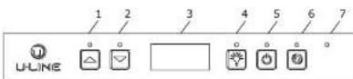
Up Down Light Power Not Used LED U-LINECONTROL FUNCTION GUIDE
| FUNCTION | COMMAND | DISPLAY/OPTIONS |
| ON/OFF | Press 🔒 and release | Unit will immediately turn ON or OFF. |
| Toggle lights | Press 🔒 and release to leave interior light on for 3 hours | Glass door wine and beverage centers only. |
| Adjust refrigerator set point | Press 🔒 or 🔒 and release | When the "F" or "C" in the display is flashing, press 🔒 or 🔒 to adjust the set point temperature. |
| View temperature in unit | Press 🔒 and 🔒 together and release | The display will flash and then toggle from set point to temperature in unit. |
| Toggle between F/C | Hold 🔒 and 🔒 for 5 seconds | The display will change units. |
DOOR ALERT NOTIFICATION
When the door is left open for more than 5 minutes:
SAFETY • INSTALLATION & INTEGRATION • OPERATING INSTRUCTIONS • MAINTENANCE • SERVICE
Sabbath Mode

This unit is Star-K certified and offers a Sabbath mode. Sabbath mode disables system responses to user initiated activities and all external functions, including lighting, display and audible alarms. The unit will still maintain internal temperatures and set points. View a full list of Star-K certified U-Line units at www.star-k.org.
To enable Sabbath Mode:
- Press ☐ (4) and hold for ten seconds and release (the °F/°C symbol will flash briefly at the end of the ten second period).
- The interior light and control display (3) will go dark until user resets mode.
- NOTE: Although the display will not be visible, the temperature controls in the unit remain active and
SAFETY • INSTALLATION & INTEGRATION • OPERATING INSTRUCTIONS • MAINTENANCE • SERVICE
Airflow and Product Loading
NOTICE
The unit requires proper airflow to perform at its highest efficiency. Do not block the front grille, or the unit will not perform as expected. Do not install the unit behind a door. When loading your unit, leave space between the evaporator and product loaded. Anything in direct contact with the evaporator is subject to freezing.
When properly loaded, your U-Line unit will store up to 92 (12 oz. [330 ml]) cans or 57 (12 oz. [330 ml]) bottles.
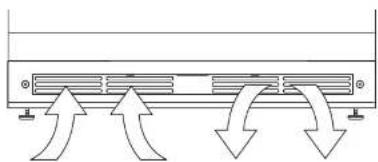
natural_image
Pure diagram of airflow or heat transfer between two air ducts with arrows indicating direction (no text or symbols)SAFETY • INSTALLATION & INTEGRATION • OPERATING INSTRUCTIONS • MAINTENANCE • SERVICE
Interior Shelves
REMOVING AND INSTALLING INTERIOR SHELVES
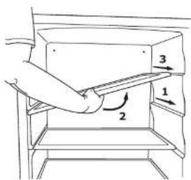
text_image
Diagram showing a hand pressing down an object with labeled parts 1, 2, and 3, indicating directional movement.For models equipped with glass shelves having recessed shelf supports, remove the shelves as follows:
- Pull shelf out about 6" (1), until back of shelf clears the "hump" on the right-hand side.
- Tilt up right-hand edge of shelf (2).
- Remove shelf from unit by pulling out (3).
Insert the shelves as follows:
NOTICE
Make sure the shelves are inserted fully into the unit.
The edge strip toward the rear prevents cans and bottles from freezing against the cold evaporator.
SAFETY • INSTALLATION & INTEGRATION • OPERATING INSTRUCTIONS • MAINTENANCE • SERVICE
Cleaning
EXTERIOR CLEANING
Vinyl Clad (Black or White)
Clean surfaces with a mild detergent and warm water solution. Do not use solvent-based or abrasive cleaners. Use a soft sponge and rinse with clean water. Wipe with a soft, clean towel to prevent water spotting.
Clean any glass surfaces with a non-chlorine glass cleaner.
Stainless Models
Stainless door panels, handles and frames can discolor when exposed to chlorine gas, pool chemicals, saltwater or cleaners with bleach.
Keep your stainless unit looking new by cleaning with a good quality all-in-one stainless steel cleaner and polish monthly. For best results use Claire® Stainless Steel Polish and Cleaner. Comparable products are acceptable. Frequent cleaning will remove surface contamination that could lead to rust. Some installations may require cleaning weekly.
Do not clean with steel wool pads.
If any surface discoloring or rusting appears, clean it quickly with Bon-Ami® or Barkeepers Friend Cleanser® and a nonabrasive cloth. Always clean with the grain. Always finish with Claire® Stainless Steel Polish and Cleaner or comparable product to prevent further problems.
Using abrasive pads such as Scotchbrite™ will cause the graining in the stainless steel to become blurred.
Rust not cleaned up promptly can penetrate the surface of the stainless steel and complete removal of the rust may not be possible.
Integrated Models
To clean integrated panels, use household cleaner per the cabinet manufacturer's recommendation.
INTERIOR CLEANING
Disconnect power to the unit.
Clean the interior and all removed components using a mild nonabrasive detergent and warm water solution applied with a soft sponge or non-abrasive cloth.
Rinse the interior using a soft sponge and clean water.
SAFETY • INSTALLATION & INTEGRATION • OPERATING INSTRUCTIONS • MAINTENANCE • SERVICE
High ambient temperature and excessive humidity can also produce frost.

CAUTION
DO NOT use an ice pick or other sharp instrument to help speed up defrosting. These instruments can puncture the inner lining or damage the cooling unit. DO NOT use any type of heater to defrost. Using a heater to speed up defrosting can cause personal injury and damage to the inner lining.
NOTICE
The drain pan was not designed to capture the water created when manually defrosting. To prevent water from overflowing the drain pan, place towels or other absorbent materials over the interior drain trough (under the evaporator) before defrosting.
To defrost:
-
Disconnect power to the unit.
-
Remove all products from the interior.
SAFETY • INSTALLATION & INTEGRATION • OPERATING INSTRUCTIONS • MAINTENANCE • SERVICE
Extended Non-Use
VACATION/HOLIDAY, PROLONGED SHUTDOWN
The following steps are recommended for periods of extended non-use:
- Remove all consumable content from the unit.
- Disconnect the power cord from its outlet/socket and leave it disconnected until the unit is returned to service.
- If ice is on the evaporator, allow ice to thaw naturally.
- Clean and dry the interior of the unit. Ensure all water has been removed from the unit.
- The door must remain open to prevent formation of mold and mildew. Open door a minimum of 2° (50 mm) to provide the necessary ventilation.
WINTERIZATION
If the unit will be exposed to temperatures of 40^ F ( 5^ C) or less, the steps above must be followed.
For questions regarding winterization, please
SAFETY • INSTALLATION & INTEGRATION • OPERATING INSTRUCTIONS • MAINTENANCE • SERVICE
Troubleshooting
BEFORE CALLING FOR SERVICE
If you think your U-Line product is malfunctioning, read the CONTROL OPERATION section to clearly understand the function of the control.
If the problem persists, read the NORMAL OPERATING SOUNDS and TROUBLESHOOTING GUIDE sections below to help you quickly identify common problems and possible causes and remedies. Most often, this will resolve the problem without the need to call for service.
IF SERVICE IS REQUIRED
If you do not understand a troubleshooting remedy, or your product needs service, contact U-Line Corporation directly at +1.800.779.2547.
When you call, you will need your product Model and Serial Numbers. This information appears on the Model and Serial number plate located on the upper right or rear wall of the interior of your product.
All models incorporate rigid foam insulated cabinets to provide high thermal efficiency and maximum sound reduction for its internal working components. Despite this
- Evaporator: Refrigerant flowing through an evaporator may sound like boiling liquid.
- Condenser Fan: Air moving through a condenser may be heard.
• Automatic Defrost Drain Pan: Water may be heard dripping or running into the drain pan when the unit is in the defrost cycle.
TROUBLESHOOTING GUIDE

DANGER
ELECTROCUTION HAZARD. Never attempt to repair or perform maintenance on the unit before disconnecting the main electrical power.
Troubleshooting - What to check when problems occur:
| Problem | Possible Cause and Remedy |
| Digital Display and Light Do Not Work. | Ensure power is connected to the unit.If the unit is cooling, it may be in Sabbath mode. |
| Interior Light Does Not Illuminate. | If the unit is cooling, it may be in Sabbath mode. |
| Light Remains on When Door Is | For glass door models, press the light icon and close the door. |
SAFETY • INSTALLATION & INTEGRATION • OPERATING INSTRUCTIONS • MAINTENANCE • SERVICE
| Problem | Possible Cause and Remedy |
| Product Is Freezing. | Because product in contact with the rear wall may freeze, ensure no product is touching the rear wall.Adjust the temperature to a warmer set point. |
| Product Is Not Cold Enough. | Air temperature does not indicate product temperature. See CHECKING PRODUCT TEMPERATURE below.Adjust the temperature to a cooler set point.Ensure unit is not located in excessive ambient temperatures or in direct sunlight.Ensure the door is closing and sealing properly.Ensure the interior light has not remained on too long.Ensure nothing is blocking the front grille, found at the bottom of the unit.Ensure the condenser coil is clean and free of any dirt or lint build-up. |
CHECKING PRODUCT TEMPERATURE
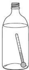
- After 24 hours, check the temperature of the water. If required, adjust the temperature control in a small increment (see CONTROL OPERATION).
Causes which affect the internal temperatures of the cabinet include:
• Temperature setting.
- Ambient temperature where installed.
• Installation in direct sunlight or near a heat source.
- The number of door openings and the time the door is open.
- The time the internal light is illuminated. (This mainly affects product on the top rack or shelf.)
• Obstruction of front grille or condenser.
SAFETY • INSTALLATION & INTEGRATION • OPERATING INSTRUCTIONS • MAINTENANCE • SERVICE
U-Line Corporation (U-Line) Limited Warranty
One Year Limited Warranty
For one year from the date of original purchase, this U-Line product warranty covers all parts and labor to repair or replace any part of the product that proves to be defective in materials or workmanship. For products installed and used for normal residential use, material cosmetic defects are included in this warranty, with coverage limited to 60 days from the date of original purchase. All service provided by U-Line under the above warranty must be performed by U-Line factory authorized service, unless otherwise specified by U-Line. Service provided during normal business hours.
Available Second Year Limited Warranty
Beyond the standard one year warranty outlined above, U-Line offers an extension of the one year warranty coverage for an additional second year from the date of purchase, free of charge. To take advantage of this second year warranty, you must register your product with U-Line within two months from the date of purchase at u-line.com providing proof of purchase.
Five Year Sealed System Limited Warranty
For five years from the date of original purchase, U-Line will repair or replace the following parts, labor not included, that prove to be defective in materials or workmanship: compressor, condenser, evaporator, drier, and all connecting tubing. All service provided by U-Line under the above warranty must be performed by U-Line factory authorized service, unless otherwise specified by U-Line. Service provided during normal business hours.
Terms
These warranties apply only to products installed in any one of the fifty states of the United States, the District of Columbia, or the ten provinces of Canada. The warranties do not cover any parts or labor to correct any defect caused by negligence, accident or improper use, maintenance, installation, service, repair, acts of God, fire, flood or other natural disasters. The product must be installed, operated, and maintained in accordance with the U-Line User Guide.
The remedies described above for each warranty are the only ones that U-Line will provide, either under these warranties or under any warranty arising by operation of law. U-Line will not be responsible for any consequential or incidental damages arising from the breach of these warranties or any other warranty, whether express, implied, or statutory. Some states do not allow the exclusion or limitation of incidental or consequential damages, so the above limitation or exclusion may not apply to you. These warranties give you specific legal rights, and you may also have other rights which vary from state to state.
Any warranty that may be implied in connection with your purchase or use of the product, including any warranty of merchantability or any warranty fit for a particular purpose is limited to the duration of these warranties, and only extends to five years in duration for the parts described in the context related to the five years limited warranty above. Some states do not allow limitations on how long an implied warranty
SAFETY • INSTALLATION & INTEGRATION • OPERATING INSTRUCTIONS • MAINTENANCE • SERVICE
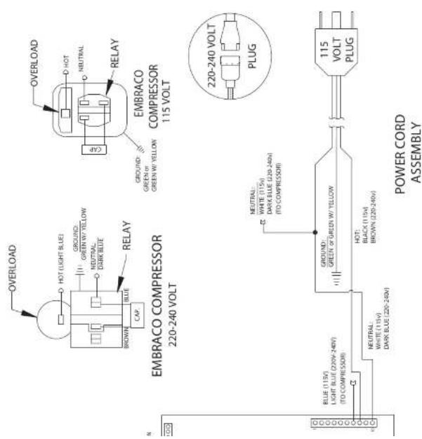
Wire Diagram
text_image
OVERLOAD D HOT NEUTRAL RELAY CREY EMBRACO COMPRESSOR 115 VOLT 220-240 VOLT PLUG OVERLOAD HOT LIGHT BLUE GROUND: GREEN W YELLOW GREEN W YELLOW NEUTRAL DAIR BLUE RELAY BROWN BLUE CAP EMBRACO COMPRESSOR 220-240 VOLT NEUTRAL: WHITE (115V) DAIR BLUE (220-240V) TO COMPRESSIONS 115 VOLT PLUG GROUNDS: GREEN & GREEN W YELLOW HOT: BLACK (115V) BROWN (220-240V) NEUTRAL WHITE (115V) DAIR BLUE (220-240V) TO COMPRESSIONS C POWER CORD ASSEMBLYSAFETY • INSTALLATION & INTEGRATION • OPERATING INSTRUCTIONS • MAINTENANCE • SERVICE
Product Liability
Field service technicians are authorized to make an initial assessment in the event of reported damages. If there are any questions about the process involved, the technician should call U-Line for further explanation.
While inspecting for defects or installation issues, photos should be taken to document any damages or issues found.
During the assessment, if the service technician is able to find the source of the damage and it can be resolved by replacement of a part, the servicer is authorized to replace the part in question. The part that caused the damage must be returned to U-Line in its entirety. The part must be clearly labeled with the serial number of the unit it was removed from, the date, and the servicer who removed the part.
If the service technician determines the damage is the result of installation issues (water connection/drain, etc.), the consumer would be notified and the issues shall be resolved at the direction of the consumer.
If damage is evident and the service technician is unable to find the source, U-Line must be contacted at 1-800-799-2547 for further direction
SAFETY • INSTALLATION & INTEGRATION • OPERATING INSTRUCTIONS • MAINTENANCE • SERVICE
Warranty Claims
The following information defines the parameters for filing a warranty claim:
- Valid serial number needed
- Valid model number needed
- Narda (or equivalent) form or submitted online at www.u-line.com
- 60 day submittal deadline from date of completed service
• Only one repair or unit per warranty claim - Refrigerant should be labeled and included on the labor submittal
- Door and water level adjustments are covered 30 days from install date.
Serial Number Requirements:
14 30911 12 XXXX
warranty status. We also accept the following information to verify warranty status:
• New Construction Occupancy Documents
- Closing Paperwork
• Final Billing - Remodel
Noting all of the following on the warranty claim will be considered proof of purchase, hard copy will not be required:
• Name of the selling Dealer
• Date of purchase/installation
• Order or Invoice number (if available)
• Description of document reviewed (i.e. store receipt, closing paperwork, etc)
Parts and labor claims are paid separately. Indicate part numbers and description for parts used in the warranty repair. Include the purchase invoice and name of the parts supplier used to procure the parts.
SAFETY • INSTALLATION & INTEGRATION • OPERATING INSTRUCTIONS • MAINTENANCE • SERVICE
Parts
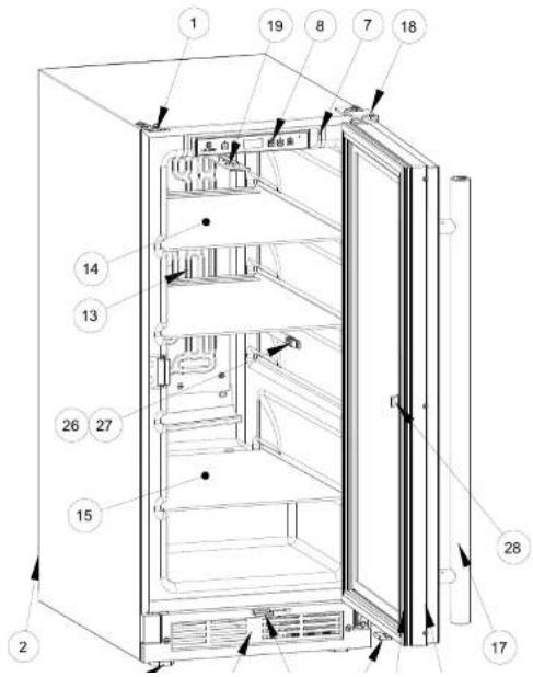
text_image
Technical diagram of an open refrigerator with numbered parts for identification and assembly reference.U-1215RSOD-00B
| Item | Description | U-Line P/N |
| 1 | Anti tip bracket w/screws | 80-54244-00 |
| 2 | Back panel | 80-54229-00 |
| 3 | Compressor electricals only | 80-54149-00 |
| 4 | Compressor w/electricals | 80-54150-00 |
| 5 | Condenser assembly | 80-54231-00 |
| 6 | Condenser fan w/screws | 80-54014-00 |
| 7 | Control Housing | 80-54259-00 |
| 8 | Display module | 80-54236-00 |
| 9 | Door assembly w/hinges | 80-54246-00 |
| 10 | Gasket, door | 80-54235-00 |
| 11 | Drain pan w/double sided tape | 80-54217-00 |
| 12 | Drier | 80-54055-00 |
| 13 | Evaporator assembly | 80-54232-00 |
| 14 | Glass shelf (1) w/edge trim | 80-54240-00 |
| 15 | Glass shelf btm | 80-54241-00 |
| 16 | Grille w/screws | 80-54230-00 |
| 17 | Handle w/logo | 80-54247-00 |
| 18 | Hinges(2) w/screws | 80-54245-00 |
| 19 | LED light strip and cover assy | 80-54000-00 |
| 20 | Leg Levelers (4) | 80-54201-00 |
| 21 | Magnet wbkt and screws (2) | 80-54250-00 |
| 22 | Main board (no case or wires) | 80-54008-00 |
| 23 | Packaging | 80-54238-00 |
| 24 | Power cord | 80-54171-00 |
| 25 | Reed switch assembly | 80-54284-00 |
SAFETY • INSTALLATION & INTEGRATION • OPERATING INSTRUCTIONS • MAINTENANCE • SERVICE
Ordering Replacement Parts
If you have a purchasing account, please utilize our service website to order parts.
Orders may also be placed by Fax or phone. See our contact information below:
www.U-LineService.com (with service login)
FAX Number: +1.414.354.5696
Phone Number: +1.800.779.2547
NOTICE
Use only genuine U-Line replacement parts. The use of non-U-Line parts can reduce speed of ice production, cause water to overflow from ice maker mold, damage the unit, and void the warranty.
Warranty parts will be shipped at no charge after U-Line confirms warranty status. Please provide the model, serial number, part number and part description. Some parts will require color or voltage information.
If U-Line requires the return of original parts, we will inform you when the parts order is taken. This requirement will be noted on your packing list. A prepaid
SAFETY · INSTALLATION & INTEGRATION · OPERATING INSTRUCTIONS · MAINTENANCE · SERVICE
System Diagnosis Guide
| System Condition | Suction Pressure | Suction Line | Compressor Discharge | Condenser | Capillary Tube | Evaporator | Wattage |
| Normal | Normal | Slightly below room temperature | Very hot | Very hot | Warm | Cold | Normal |
| Overcharge | Higher than normal | Very cold may frost heavily | Slightly warm to hot | Hot to warm | Cool | Cold | Higher than normal |
| Undercharge | Lower than normal | Warm-near room temperature | Hot | Warm | Warm | Extremely cold near inlet - Outlet below room temperature | Lower than normal |
| Partial Restriction | Somewhat lower than normal vacuum | Warm - near room temperature | Very hot | Top passes warm - Lower passes cool (near room temperature) due to liquid | Room temperature (cool) or colder | Extremely cold near inlet - Outlet below room temperature backing up | Lower than normal |
| Complete Restriction | In deep vacuum | Room temperature (cool) | Room temperature (cool) | Room temperature (cool) | Room temperature (cool) | No refrigeration | Lower than normal |
| No Gas | 0 PSIG to 25° | Room temperature (cool) | Cool to hot | Room temperature (cool) | Room temperature (cool) | No refrigeration | Lower than normal |
SAFETY • INSTALLATION & INTEGRATION • OPERATING INSTRUCTIONS • MAINTENANCE • SERVICE
Compressor Specifications

DANGER
Electrocution can cause death or serious injury. Burns from hot or cold surfaces can cause serious injury. Take precautions when servicing this unit.
Disconnect the power source.
Do not stand in standing water when working around electrical appliances.
Make sure the surfaces you touch are not hot or frozen.
Do not touch a bare circuit board unless you are wearing an anti-static wrist strap that is grounded to an electrical ground or grounded water pipe.
Handle circuit boards carefully and avoid touching components.
To measure the start winding resistance, measure across

text_image
OVERLOAD PROTECTOR STARTING RELAY RELAY COVER CAPACITOR| EMX20CLC | |
| Refrigerant | R600a |
| Voltage | 115 - 127 VAC |
| Frequency | 60 Hz |
| Run Cap | 12μF/165 VAC |
| Start Winding | 6.7 Ohm at 77°F |
| Run Winding | 12.6 Ohm at 77°F |
| LRA | 3.7 A |
| FLA | 0.5 A |
| Starting Device | 8EA14C |
| Overload | 4TM142RFBYY-53 |
* All resistance readings are ±10%
SAFETY • INSTALLATION & INTEGRATION • OPERATING INSTRUCTIONS • MAINTENANCE • SERVICE
Troubleshooting - Extended
CAUTION
Never attempt to repair or perform maintenance on the unit until the main electrical power has been disconnected from the unit.
SPECIFIC ERRORS AND ISSUES
The technically advanced diagnostic capabilities of the electronic controls utilized on the 1200 and 2200 series units allows for easy and thorough troubleshooting.
Navigation of the control is the key and is explained in the CONTROL OPERATION section of the manual, along with control button layout, control function descriptions, a service mode menu and service menu selection explanations.
Verification of temperature and thermistor performance can be identified by directly viewing thermistor readings in the service mode.
Component failure issues can be identified through service mode menu #19, "Component Testing." Individual components can be switched on and off to check for both proper function of a specific component and also delivery
All models incorporate rigid foam insulated cabinets to provide high thermal efficiency and maximum sound reduction for its internal working components. Despite this technology, your model may make sounds that are unfamiliar.
Normal operating sounds may be more noticeable because of the unit's environment. Hard surfaces such as cabinets, wood, vinyl or tiled floors and paneled walls have a tendency to reflect normal appliance operating noises.
Listed below are common refrigeration components with a brief description of the normal operating sounds they make. NOTE: Your product may not contain all the components listed.
- Compressor: The compressor makes a hum or pulsing sound that may be heard when it operates.
- Evaporator: Refrigerant flowing through an evaporator may sound like boiling liquid.
- Condenser Fan: Air moving through a condenser may be heard.
• Automatic Defrost Drain Pan: Water may be heard
SAFETY • INSTALLATION & INTEGRATION • OPERATING INSTRUCTIONS • MAINTENANCE • SERVICE
TROUBLESHOOTING GUIDE
| Concern | Potential Causes | Suggested Remedy |
| Not Cooling | Compressor overheating | Verify proper air flow through condenser. Is condenser clean? |
| Confirm condenser fan operation. | ||
| Confirm proper compressor operating voltage. Use #19, Component Testing in Service Mode. | ||
| Compressor not operating | Confirm proper compressor operating voltage. Use #19, Component Testing in Service Mode. | |
| Test overload and relay, replace as needed. | ||
| Compressor operating - no cooling | Refer to System Diagnosis Guide. | |
| Evaporator fan not operating | Use #19, Component Testing in Service Mode. | |
| Frozen Product | Control set too cold | Adjust Set Point Temp accordingly. |
| Review logged error codes | Refer to #14, Error Log in Service Mode. | |
| Thermistor failure | Check Error Log in Service Mode, OHM thermistor. | |
| Frost Bulldup Inside Unit | Door Ajar or Restricted from Closing | Check door clearance to adjoining cabinetry. Check distribution of product in unit. |
| Evaporator fan not operating | Use Relay Toggle, Component Testing in Service Mode. | |
| Thermistor failure | Check Error Log. | |
| Display Not Working | Unit placed in Sabbath mode? | Press and hold for 5 seconds to check. |
| Display unplugged | Verify that both ends of the display wiring are firmly connected. | |
| Display wiring broken or damaged | Perform continuity test of wiring and replace as needed. | |
| Internal Lights Not Working | Control Setting | Unit set to Sabbath Mode. Press and hold for 5 seconds to check. |
| Door switch misaligned or defective | Check the function of reed switch and door magnet adjustment. | |
| Noisy | Refrigeration tubing touching cabinet | Carefully reposition tubing. |
| Fan blade obstruction (wiring, foam insulation, packaging material) | Remove obstruction. |
SAFETY • INSTALLATION & INTEGRATION • OPERATING INSTRUCTIONS • MAINTENANCE • SERVICE
MAIN CONTROL
The main control board is very robust and is rarely the cause of system issues. It is important to fully diagnose the board for any suspected failures before attempting to remove the board for replacement or service. Follow the guidelines below to fully test and diagnose the main control.
Power Fault
If the unit does not (or seems to not) power on, follow the flow chart below to help diagnose the issue. Before beginning it is important to first verify the unit is not simply set to sabbath mode.
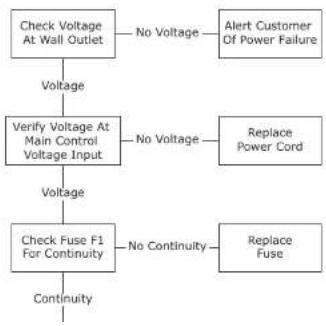
flowchart
graph TD
    A["Check Voltage At Wall Outlet"] -->|Voltage| B["Verify Voltage At Main Control Voltage Input"]
    B -->|Voltage| C["Check Fuse F1 For Continuity"]
    C -->|Continuity| D["Continue"]
    A -->|No Voltage| E["Alert Customer Of Power Failure"]
    B -->|No Voltage| F["Replace Power Cord"]
    C -->|No Continuity| G["Replace Fuse"]
Testing The Main Control
If the main control is suspected of being faulty, the following procedure should be performed to verify main control for functionality.
Relay & DC Outputs
One of the primary functions of the main control is to operate the multiple relay and DC outputs during each cycle. Verify proper operation of these relays using the following procedure.
- Enter "Relay Toggle" through the service menu.
NOTICE
Frequently toggling the compressor relay could force the compressor into overload. The compressor will automatically deactivate during an overload and will remain deactivated until the overload switch cools. This could take some time. It is important to allow the compressor at least 5 minutes off time between relay cycles.
- Toggle the relay. Its related component should activate / deactivate with the switching of the relay. If it does not, test component.
Other Suspected Main Control Faults
SAFETY • INSTALLATION & INTEGRATION • OPERATING INSTRUCTIONS • MAINTENANCE • SERVICE
REED SWITCH
A reed switch is used to monitor door state. When the door is closed magnetic force pulls the reed to its contact and closes the circuit which turns the light and display off. When the door is open the reed pulls away from the contact and opens the circuit. If the door is left open for longer than 5 minutes, the switch will trigger an error code and set an audible warning.
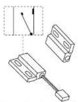
Magnet Away From Switch
(Door Open)
(Switch Open)
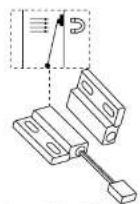
Magnet Close To Switch (Door Closed) (Switch Closed)
SAFETY · INSTALLATION & INTEGRATION · OPERATING INSTRUCTIONS · MAINTENANCE · SERVICE
Control Operation - Service
UI BUTTON LAYOUT
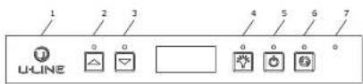
1. Hidden Button
-Accesses Service Menu
-No LED directly above. All LEDs turn on with button activation except #7.
2. Up Button
-Increases temperature
-Navigates through service menu
-LED activated with button activation.
3. Down Button
- Decreases temperature
-Navigates through service menu
-LED activated with button activation
4. Light Button
-Activates light for 3 hours on select models
-Used to select items in service menu
-LED activated with button activation
SAFETY · INSTALLATION & INTEGRATION · OPERATING INSTRUCTIONS · MAINTENANCE · SERVICE
CONTROL FUNCTION QUICK GUIDE
| FUNCTION | COMMAND | DISPLAY/ OPTIONS |
| ON/OFF | Press 🎨 and release | Unit will immediately turn ON or OFF |
| Toggle lights | Press 🎨 and release to leave interior light on for 3 hours | Glass door wine captains and beverage centers only. |
| Adjust refrigerator temperature | Push 🎨 or 🎨 and release | When the “F” or “C” in the display is flashing, push 🎨 or 🎨 to adjust the set point temperature. |
| View temperature in unit | Push 🎨 and 🎨 and release the together | The display will flash and then toggle from set point to temperature in unit. |
| Toggle between F/C | Hold the 🎨 and 🎨 for five seconds | The display will change units. |
DOOR ALERT NOTIFICATION
When the door is left open for more than 5 minutes:
• An audible tone will sound for several seconds every minute.
- "dr" will appear in display.
Close door to silence alert and reset.
VIEWING ACTUAL TEMPERATURE
In viewing temperature in these modes any offsets are taken into account. This means that if you place a thermistor in a known temperature, let's say ice water, it may not read the 32°F that you would assume. If the control offset was preset at -3°F while you placed the thermistor in an icebath, the actual thermistor reading when viewing
When the degree symbol is flashing the unit will allow the use of the control for demonstrations. The unit can be left in this mode indefinitely.
SERVICE MODE
This mode has options available for service diagnostics. To enter the mode hold the hidden key for 10 seconds. The display will show "0." When in this mode use the up and down arrows to select the desired option. The LIGHT key is the ENTER key and will initiate the function. If changing a setting, you must press the LIGHT key again to retain the changed setting. To exit the service mode scroll to option "0" and press the LIGHT key. After five minutes of not touching any keys the mode will also exit automatically.
SAFETY · INSTALLATION & INTEGRATION · OPERATING INSTRUCTIONS · MAINTENANCE · SERVICE
SERVICE MODE GUIDE
| # | Service Mode Menu Item |
| 1 | View thermistor # 1 (no offsets) |
| 2 | View thermistor # 2 (no offsets) |
| 3 | View thermistor # 3 (no offsets) |
| 4 | View thermistor # 4 (no offsets) |
| 5 | Adjust thermistor # 1 offset |
| 6 | Adjust thermistor # 2 offset |
| 7 | Adjust thermistor # 3 offset |
| 8 | Adjust thermistor # 4 offset |
| 9 | View thermistor # 2 set point no offsets |
| 10 | View thermistor # 3 set point no offsets |
| 11 | View thermistor # 4 set point no offsets |
| 12 | Adjust defrost interval 3 to 24 hours |
| 13 | Adjust defrost duration 0 to 99 minutes |
| 14 | View error log |
| 15 | Clear error log |
| 16 | Adjust thermistor # 1 differential |
| 17 | Adjust evaporator fan delay in minutes (start of cooling cycle) 0 - 99 minutes |
| 18 | Adjust evaporator fan delay in minutes (after cooling cycle stops) 0 - 99 minutes |
| 19 | Individual component toggle |
| 20 | Model number indicator |
| 21 | Light all LED segments of display |
| 22 | View defrost cycles |
| 23 | View compressor run time |
| 24 | Activate defrost/harvest |
SERVICE MODE GUIDE
1. THERMISTOR 1 — ZONE
This shows the pure thermistor reading with no offsets taken into account.
2. THERMI STOR 2 — EVAPORATOR
This shows the pure thermistor reading with no offsets taken into account.
3. Does not apply to this model.
4. Does not apply to this model.
5. THERMISTOR 1 — ZONE OFFSET
(DO NOT MAKE AN ADJUSTMENT TO THIS WITHOUT CONTACTING TECH LINE: 800-779-2547)
This calibration is only to be used if actual temperature at thermistor #1 is off from set point.
By adjusting the offset higher we can force the unit to drive the temperature down below the set point. (example: adjusting from 0 to +2 will drop the unit temperature 2 degrees)
6. THERMISTOR 2 — EVAPORATOR OFFSET
(DO NOT MAKE AN ADJUSTMENT TO THIS WITHOUT CONTACTING TECH LINE: 800-779-2547)
7. Does not apply to this model.
8. Does not apply to this model.
9. THERMISTOR 2 — SET POINT MINUS OFFSET
This shows the thermistor reading with offsets taken into account.
SAFETY · INSTALLATION & INTEGRATION · OPERATING INSTRUCTIONS · MAINTENANCE · SERVICE
14. VIEW ERROR LOG
A list of the errors in the order they occurred will scroll once on the display. All errors are logged in memory. Only door error is displayed on the display and has an audible signal.
E0: Door 1 (upper) open.
E1: Thermistor 1 open.
E2: Thermistor 2 open.
E3: Thermistor 3 open.
E4: Thermistor 4 open (Does not apply to this model).
E5: Thermistor 1 shorted.
E6: Thermistor 2 shorted.
E7: Thermistor 3 shorted.
E8: Thermistor 4 shorted (Does not apply to this model).
E9: Door 2 (lower) open.
P1: Pump Circuit open (Does not apply to this
model).
15. CLEAR ERROR LOG
To clear errors, press and hold ☐ (5 seconds) when CLR is flashing.
16. THERMISTOR — 1 DIFFERENTIAL
This number should not be adjusted.
-
Does not apply to this model.
-
Does not apply to this model.
19. INDIVIDUAL COMPONENT TOGGLE
| Display # | Relay/ Output |
| 0 | Exit |
| 2 | Relay 2 |
| 3 | Relay 3 |
21. LIGHT ALL LED SEGMENTS
This will illuminate all the LEDs on the display to ensure they work properly.
22. VIEW DEFROST CYCLES
Displays the number of defrosts that have occurred in the past 24 hours.
23. VIEW COMPRESSOR RUNTIME
This will show the number of minutes the compressor has run in the prior cycle (or current cycle if the compressor was running when service mode was entered).
24. ACTIVATE DEFROST/HARVEST
Turns on the hot gas bypass valve allowing hot gas to circulate through the evaporator causing frost to melt.
25. RESTORE FACTORY DEFAULTS
Will restore all adjustable functions to their factory settings.
26. SOFTWARE VERSION — MAIN BOARD
Displays software version of the main control board.
27. SOFTWARE VERSION — USER INTERFACE
Displays software version of the user interface.
28. LOG IN PERIOD
Factory use only - do not adjust.
29. FACTORY TEST MODE
SAFETY · INSTALLATION & INTEGRATION · OPERATING INSTRUCTIONS · MAINTENANCE · SERVICE
MODEL LIST
| 1000 | MODEL INDICATOR | 2000 (120V) | MODEL INDICATOR | 2000 (230V) | MODEL INDICATOR | ||
| 1215R | 07 | 2218R | 05 | 2245R | 55 | ||
| 1215WC | 12 | 2218RGL | 04 | 2245DC | 54 | ||
| 1224BEV | 13 | 2218WC | 06 | 2245WC | 56 | ||
| 1224DWR | 08 | 2224BEV | 00 | 2260DC | 50 | ||
| 1224R | 14 | 2224FZR | 11 | 2260FZR | 57 | ||
| 1224RF | 09 | 2224R | 02 | 2260R | 52 | ||
| 1224RSOD | 10 | 2224RGL | 01 | 2260RDC | 51 | ||
| 1224WC | 15 | 2224WC | 03 | 2260WC | 53 | ||
| CLR1215 | 18 | 2224ZWC | 59 | 2260ZWC | 58 | ||
| CO1224F | 19 | ADA24R | 17 |
PROGRAMMING THE UNIT TO CORRECT MODEL NUMBER
- Disconnect the unit from power source.
- Push and hold the U-Line button.
- While still holding the U-Line button, plug the unit into the appropriate power source.
- When the flashing digits appear (3-5 seconds), use the up and down arrow buttons to select the appropriate model number*. or
*(See Above "Model List")
- Press the light bulb button once.
- The display will blink, and then will appear as the programmed display.
SAFETY · INSTALLATION & INTEGRATION · OPERATING INSTRUCTIONS · MAINTENANCE · SERVICE
Relay / Output Chart
| 5 | Relay 6 | Relay 7 | DC Output 1 | DC Output 2 | DC Output 3 | DC Output 4 | DC Output 5 |
| N/A | Compressor | Light | Evaporator Fan | Condenser Fan | N/A | N/A | |
| N/A | Compressor | Light | Evaporator Fan | Condenser Fan | N/A | N/A | |
| N/A | Compressor | Light | Evaporator Fan | Condenser Fan | N/A | N/A | |
| N/A | Compressor | Top Light | Evaporator Fan | Condenser Fan | N/A | Bottom Light | |
| N/A | Compressor | Light | Evaporator Fan | Condenser Fan | N/A | N/A | |
| s Valve | N/A | Compressor | Light | Evaporator Fan | Condenser Fan | N/A | N/A |
| N/A | Compressor | Light | Evaporator Fan | Condenser Fan | N/A | N/A | |
| N/A | Compressor | Light | Evaporator Fan | Condenser Fan | N/A | N/A | |
| N/A | Compressor | Light | Evaporator Fan | Condenser Fan | N/A | N/A | |
| N/A | Compressor | Light | Evaporator Fan | Condenser Fan | N/A | A | |
| s Valve | Condenser Fan | Compressor | Light | N/A | N/A | N/A | N/A |
| s Valve | N/A | Compressor | Light | Evaporator Fan | Condenser Fan | N/A | N/A |
| N/A | Compressor | Light | Evaporator Fan | Condenser Fan | N/A | N/A | |
| N/A | Compressor | Light | Evaporator Fan | Condenser Fan | N/A | N/A | |
| N/A | Compressor | Light | Evaporator Fan | Condenser Fan | N/A | N/A | |
| N/A | Compressor | Light | Evaporator Fan | Condenser Fan | N/A | N/A | |
| N/A | Compressor | Light | Evaporator Fan | Condenser Fan | N/A | N/A | |
| N/A | Compressor | Light | Evaporator Fan | Condenser Fan | N/A | N/A | |
| N/A | Compressor | ||||||
| N/A | Compressor | Light | Evaporator Fan | Condenser Fan | N/A | N/A | |
| N/A | Compressor | Light | Evaporator Fan | Condenser Fan | N/A | N/A | |
| N/A | Compressor | Light | Evaporator Fan | Condenser Fan | N/A | N/A | |
| N/A | Compressor | Light | Evaporator Fan | Condenser Fan | NA | N/A | |
| N/A | Compressor | Light | Evaporator Fan | Condenser Fan | N/A | Bottom Light | |
| N/A | Compressor | Light | Evaporator Fan | Condenser Fan | N/A | N/A | |
| N/A | Compressor | Light | Evaporator Fan | Condenser Fan | N/A | N/A | |
| N/A | Compressor | Light | Evaporator Fan | Condenser Fan | N/A | N/A | |
| N/A | Compressor | Light | Evaporator Fan | Condenser Fan | NN/A | N/A | |
| N/A | Compressor | Light | Evaporator Fan | Condenser Fan | N/A | N/A | |
| N/A | Compressor | Light | Evaporator Fan | Condenser Fan | N/A | N/A | |
| N/A | Compressor | Light | Evaporator Fan | Condenser Fan | N/A | N/A |
SAFETY • INSTALLATION & INTEGRATION • OPERATING INSTRUCTIONS • MAINTENANCE • SERVICE
Thermistors
Thermistors are used for various temperature readings. Thermistors provide reliable temperature readings using a resistance which varies based on surrounding temperatures. If a faulty thermistor is suspected it may be tested using an accurate ohmmeter.
Both thermistors in the unit are identical. If a thermistor is suspected of being defective, the resistance can be verified. Place the thermistor in an ice water bath, the resistance should read 16.1k OHMs +/-5% on your meter.
Thermistor connections must be kept clean. A thermistor connection that has become corroded can cause resistance values from the thermistor to change as they pass through a dirty connection to the board.
It is for that reason that we apply dielectric grease to all of our thermistor connections. Dielectric grease will help to keep thermistor connections clean and dry.
If you change a thermistor in the unit please re-apply dielectric grease to the connection. If you encounter a dirty thermistor connection, you should replace the thermistor and the thermistor harness.
Thermistor error information can be found in the Control Operations - Service section.
1000 Series Self Preservation Mode: The unit will cycle on for 10 minutes then off for 40 minutes.
Evaporator Thermistor
If the evaporator thermistor fails, the unit will rely on a preset defrost timer during defrost cycles. The unit will otherwise operate normally. Refer to defrost section.
Thermistor Resistance Data
| Temp (F) | Temp (C) | Nominal Resistance (OHMS)* |
| -40 | -40 | 169157 |
| -31 | -35 | 121795 |
| -22 | -30 | 88766 |
| -13 | -25 | 65333 |
| -4 | -20 | 48614 |
| 5 | -15 | 36503 |
| 14 | -10 | 27681 |
| 23 | -5 | 21166 |
| 32 | 0 | 16330 |
| 41 | 5 | 12696 |
| 50 | 10 | 9951 |
| 59 | 15 | 7855 |
| 68 | 20 | 6246 |
| 77 | 25 | 5000 |
| 86 | 30 | 4029 |
SAFETY • INSTALLATION & INTEGRATION • OPERATING INSTRUCTIONS • MAINTENANCE • SERVICE
Defrost
The models below have automatic or frost free design and do not require manual defrosting under normal conditions.
| Defrost Settings | ||||
| Base Model | Variant(s) | Compressor Run Time Between Defrost (Hours) | Duration in Minutes (Maximum) | Stop Temperature °F (°C) |
| 1224 | RF | 12 | 45 | 15 (-9) |
| 1215/1224/2218/2245/2224/2260 | WC, ZWC | 12 | 45 | 45 (7) |
| 1215/1224/2218/2245/2224/2260 | R, RSOD, RDC, BEV, DC, DWR, RGL | 12 | 45 | 42 (6) |
| CO29 | F | 12 | 18 | n/a |
| CO1224 | F | 12 | 18 | 45 (7) |
| 1224FZR | Freezer Mode | 6 | 45 | 42(6) |
| 1224FZR | Refrigerator Mode | 12 | 45 | 42(6) |
The defrost settings for 3000 series models are determined by zone.
| Defrost Settings by Zone (3000 Series) | ||||
| Zones | Compressor Run Time Between Defrost (Hours) | Duration in Minutes (Minimum) | Duration in Minutes (Maximum) | Stop Temperature °F (°C) |
| Beverage/Drinks | 12 | 5 | 60 | 42 (6) |
| Market/Fresh | 12 | 5 | 60 | 42 (6) |
| Root/Root Cellar | 12 | 5 | 60 | 45 (7) |
| Pantry | 12 | 5 | 60 | 42 (6) |
| White Wine | 12 | 5 | 60 | 45 (7) |
| Red Wine | 12 | 5 | 60 | 45 (7) |
| Sparkling Wine | 12 | 5 | 60 | 45 (7) |
| Polar | 6 | 5 | 20 | 42 (6) |