3018RGL15B - Fridge U-Line - Free user manual and instructions
Find the device manual for free 3018RGL15B U-Line in PDF.

User questions about 3018RGL15B U-Line
0 question about this device. Answer the ones you know or ask your own.
Ask a new question about this device
Download the instructions for your Fridge in PDF format for free! Find your manual 3018RGL15B - U-Line and take your electronic device back in hand. On this page are published all the documents necessary for the use of your device. 3018RGL15B by U-Line.
USER MANUAL 3018RGL15B U-Line
USER GUIDE & SERVICE MANUAL
SAFETY • INSTALLATION & INTEGRATION • OPERATING INSTRUCTIONS • MAINTENANCE • SERVICE

natural_image
Modern kitchen interior with white walls, stainless steel appliances, and a brick wall with fire hydrant (no visible text or symbols)SAFETY • INSTALLATION & INTEGRATION • OPERATING INSTRUCTIONS • MAINTENANCE • SERVICE
Tip: Click on any section below to jump directly there
Contents
Intro
Safety
Safety and Warning
Disposal and Recycling
Service
Troubleshooting
Warranty
Service Extended
Installation
Environmental Requirements
Electrical
Cutout Dimensions
Product Dimensions
Side by Side Installation
Anti-Tip Bracket
General Installation
Integrated Grille / Plinth Dimensions
Grille / Plinth Installation
Door Stop
Door Adjust
Wire Diagram
Product Liability
Warranty Claims
Parts
Ordering Replacement Parts
System Diagnosis Guide
Compressor Specifications
Troubleshooting Extended
Control Quick Guide
Thermistor
Defrost
Remove Fan and Cover
WELCOME TO U-LINE
Congratulations on your U-Line purchase. Your product comes from a company with over five decades of premium modular ice making, refrigeration, and wine preservation experience. U-Line continues to be the American leader, delivering versatility and flexibility for multiple applications including residential, light commercial, outdoor and marine use. U-Line's complete product collection includes Wine Captain ^® Models, Beverage Centers, Clear Ice Machines, Crescent Ice Makers, Glass & Solid Door Refrigerators, Drawer Models, Freezers, Combo ^® Models, and more.
U-Line has captivated those with an appreciation for the finer things with exceptional functionality, style, inspired innovations and attention to even the smallest details. We are known and respected for our unwavering dedication to product design, quality and selection. U-Line is headquartered in Milwaukee, Wisconsin and has shipped product to five continents for over two decades and is proud to have the opportunity to ship to you.
PRODUCT INFORMATION
Looking for additional information on your product? User Guides, Spec Sheets, CAD Drawings, Compliance Documentation, and Product Warranty information are all available for reference and download at u-line.com.
PROPERTY DAMAGE / INJURY CONCERNS
In the unlikely event property damage or personal injury is suspected related to a U-Line product, please take the following steps:
- U-Line Customer Care must be contacted immediately at +1.800.779.2547.
- Service or repairs performed on the unit without prior written approval from U-Line is not permitted. If the unit has been altered or repaired in the field without prior written approval from U-Line, claims will not be eligible.
SAFETY · INSTALLATION & INTEGRATION · OPERATING INSTRUCTIONS · MAINTENANCE · SERVICE
Safety and Warning
NOTICE
Please read all instructions before installing, operating, or servicing the appliance.
Use this appliance for its intended purpose only and follow these general precautions with those listed throughout this guide:
SAFETY ALERT DEFINITIONS
Throughout this guide are safety items labeled with a Danger, Warning or Caution based on the risk type:
DANGER
Danger means that failure to follow this safety statement will result in severe personal injury or death.
WARNING
Warning means that failure to follow this safety statement could result in serious personal injury or death.
DANGER
This unit contains R600a (Isobutane) which is a flammable hydrocarbon. It is safe for regular use. Do not use sharp objects to expedite defrosting. Do not service without consulting the "R600a specifications" section included in the User Guide. Do not damage the refrigerant circuit.
WARNING
Service must be done by factory authorized service personnel. Any parts shall be replaced with like components. Failure to comply could increase the risk of possible ignition due to incorrect parts or improper service.
SAFETY • INSTALLATION & INTEGRATION • OPERATING INSTRUCTIONS • MAINTENANCE • SERVICE
Disposal and Recycling

DANGER
RISK OF CHILD ENTRAPMENT. Before you throw away your old refrigerator or freezer, take off the doors and leave shelves in place so children may not easily climb inside.
If the unit is being removed from service for disposal, check and obey all federal, state and local regulations regarding the disposal and recycling of refrigeration appliances, and follow these steps completely:
- Remove all consumable contents from the unit.
- Unplug the electrical cord from its socket.
- Remove the door(s)/drawer(s).
SAFETY • INSTALLATION & INTEGRATION • OPERATING INSTRUCTIONS • MAINTENANCE • SERVICE
Environmental Requirements
This model is intended for indoor/interior applications only and is not to be used in installations that are open/exposed to natural elements.
This unit is designed to operate between 50°F (10°C) and 100°F (38°C). Higher ambient temperatures may reduce the unit's ability to reach low temperatures and/or reduce ice production on applicable models.
For best performance, keep the unit out of direct sunlight and away from heat generating equipment.
In climates where high humidity and dew points are present, condensation may appear on outside surfaces. This is considered normal. The condensation will evaporate when the humidity drops.
CAUTION
Damages caused by ambient temperatures of 40^ F ( 4^ C) or below are not covered by the warranty.
SAFETY • INSTALLATION & INTEGRATION • OPERATING INSTRUCTIONS • MAINTENANCE • SERVICE
Electrical
WARNING
SHOCK HAZARD — Electrical Grounding Required. Never attempt to repair or perform maintenance on the unit until the electricity has been disconnected.
Never remove the round grounding prong from the plug and never use a two-prong grounding adapter.
Altering, cutting or removing power cord, removing power plug, or direct wiring can cause serious injury, fire, loss of property and/or life, and will void the warranty.
Never use an extension cord to connect power to the unit.
Always keep your working area dry.
NOTICE
Electrical installation must observe all state and local codes. This unit requires connection to a
SAFETY • INSTALLATION & INTEGRATION • OPERATING INSTRUCTIONS • MAINTENANCE • SERVICE
Cutout Dimensions
PREPARE SITE
Your U-Line product has been designed exclusively for a built-in installation. When built-in, your unit does not require additional air space for top, sides, or rear. However, the front grille must NOT be obstructed.
The product is designed and manufactured for seamless integration in the specified cutout opening shown, which requires precise measurements. The opening must be square and plumb front to back. Although not required, you may choose to increase the overall cutout width for ease of installation.
The Modular 3000 Series units are engineered with a variety of adjustment features to help ensure a seamless installation. Adjustable doors, leveling legs and grille will assist in fine tuning the installation.
All 3000 Series models fully integrate into overlay/face frame, inset or European/frameless cabinet styles and install seamlessly into standard 24" (610 mm) depth cabinet base.
CUTOUT DIMENSIONS

text_image
33-7/8" (860 mm) to 34-7/8" (886 mm) 5/6" (16 mm) 24" (610 mm) 7" (178 mm) 4" (102 mm) 17-7/8" (455 mm)Metric measurements rounded and optimized.
CAUTION
SAFETY • INSTALLATION & INTEGRATION • OPERATING INSTRUCTIONS • MAINTENANCE • SERVICE
Product Dimensions
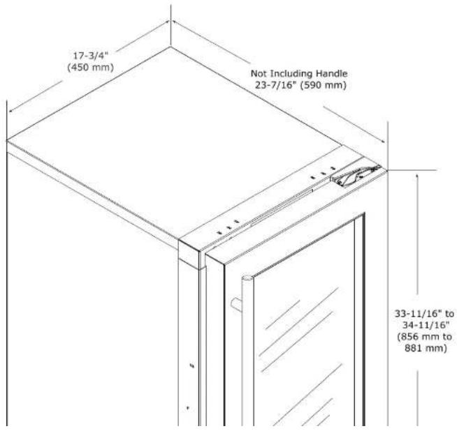
text_image
17-3/4" (450 mm) Not Including Handle 23-7/16" (590 mm) 33-11/16" to 34-11/16" (856 mm to 881 mm)SAFETY • INSTALLATION & INTEGRATION • OPERATING INSTRUCTIONS • MAINTENANCE • SERVICE
Side-by-Side Installation
OTHER SITE REQUIREMENTS
Side-by-Side Installation
Units must operate from separate, properly grounded electrical receptacles placed according to each unit's electrical specifications requirements.
Cutout width for a side-by-side installation is the total of the widths listed under Cutout Dimensions in each unit's Installation Guide. Each door can be opened individually (one at a time) without interference.

natural_image
Pure technical line drawing of a structural frame or support structure without any text, numbers, or symbolsHowever, to ensure unobstructed door swing (opening both doors at the same time), 1/4" (6.4 mm) of space
Hinge-by-Hinge Installation (Mullion)
When installing two units hinge-by-hinge, 13/16" (22 mm) is required for integrated models. Additional space may be needed for any knobs, pulls or handles installed.

text_image
-13/16" (22 mm)Stainless steel models which include the standard stainless handle will require 4-9/16" (116 mm) to allow both doors to open to 90° at the same time.
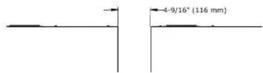
text_image
4-9/16" (116 mm)SAFETY • INSTALLATION & INTEGRATION • OPERATING INSTRUCTIONS • MAINTENANCE • SERVICE
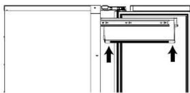
Anti-Tip Bracket

CAUTION
The anti-tip bracket must be installed to prevent the unit from tipping when doors are fully opened or excess weight is placed on the front of the unit.
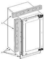
The anti-tip bracket has multiple mounting options. Mounting will depend on your particular cabinet configuration. Locate 3 #8x5/8' screws included with your unit.
TOP MOUNT
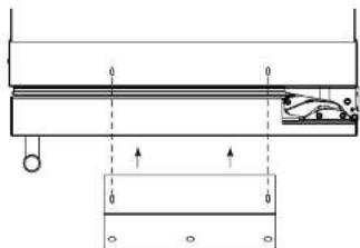
natural_image
Pure mechanical diagram showing a beam with supports and a sliding component, without any text, numbers, or symbols.For ease of installation, the anti-tip bracket is pre-installed in the top mount position.
SIDE MOUNT
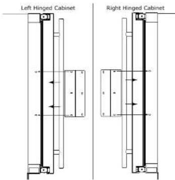
text_image
Left Hinged Cabinet Right Hinged CabinetSide mount position is used when you are unable to mount the bracket to the underside of your countertop.
- Remove the pre-installed anti-tip bracket from the top mount position and align the bracket to the hinge side of the unit as shown above.
-
Reinstall the 2 #8x5/8" screws into the plate using a #2 Phillips head screwdriver.
-
Correlation slide the cell into the solution to the
SAFETY • INSTALLATION & INTEGRATION • OPERATING INSTRUCTIONS • MAINTENANCE • SERVICE
General Installation
LEVELING INFORMATION
-
Use a level to confirm the unit is level. Level should be placed along top edge and side edge as shown.
-
If the unit is not level, remove grille and adjust legs as necessary. Use included tool to adjust the height of the rear l
text_image
Technical diagram of a device with labeled components and dimension lines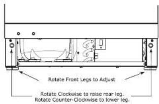
text_image
Rotate Front Legs to Adjust Rotate Clockwise to raise rear leg. Rotate Counter-Clockwise to lower leg.- Confirm the unit is level after each adjustment and repeat the previous steps until the unit is level.
INSTALLATION
- Plug in the power/electrical cord.
- Gently push the unit into position. Be careful not to entangle the cord.
- Re-check the leveling, from front to back and side to side. Make any necessary adjustments. The unit's top surface should be approximately 1/8" (3 mm) below the countertop.
- Install the anti-tip bracket.
- Remove the interior packing material and wipe out the inside of the unit with a clean, water-dampened cloth.
SAFETY • INSTALLATION & INTEGRATION • OPERATING INSTRUCTIONS • MAINTENANCE • SERVICE
Integrated Grille - Plinth Dimensions
PREPARE AND INSTALL INTEGRATED GRILLE (PLINTH STRIP/BASE FASCIA)
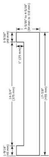
- Use the dimensions provided in the diagram to cut and shape your integrated grille (plinth strip/base fascia) panel. Recommended panel thickness is between 1/4" (6 mm) and 3/8" (9 mm). Height will vary from 3-5/16" (84 mm) to 4-5/16" (110 mm) based on your grille (plinth strip/base fascia) height.
- Finish or stain your grille (plinth strip/base fascia) panel to match your surrounding furniture. Finish front, back and edges to prevent warping. Carefully follow the manufacturer's recommendations for finish application and cure times.
- Apply double sided tape to the backside of the integrated grill (plinth strip/base fascia). Use the diagram below for reference. U-Line recommends 3M™ VHB™ tape, a high strength bonding tape.
Apply Tape To Shaded Area

INTEGRATED GRILLE (PLINTH STRIP/BASE FASCIA) DIMENSIONS
text_image
1-2/16" (40 mm) 14-3/4" (375 mm) 1" (25 mm) 3-5/16" to 4-5/16" (84 mm to 110 mm) 17-2/8" (455 mm)SAFETY • INSTALLATION & INTEGRATION • OPERATING INSTRUCTIONS • MAINTENANCE • SERVICE
Grille - Plinth Installation
REMOVING AND INSTALLING GRILLE (PLINTH STRIP/BASE FASCIA)

Disconnect electrical current to the unit before removing the grille (plinth strip/base fascia).
When using the unit, the grille (plinth strip/base fascia) must be installed.
Edges of sheet metal may be sharp.
Removing the grille (plinth strip/base fascia)
-
Disconnect electrical current to unit.
-
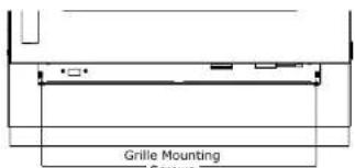
Using the included 7/64" Allen wrench, loosen (but do not remove) both grille (plinth strip/base fascia) lock screws. See below.
text_image
Grille Mounting ScrewsInstalling the grille (plinth strip/base fascia)
-
Align slots in grille (plinth strip/base fascia) rail with screw heads in base of unit
-
Push grille (plinth strip/base fascia) rails towards the center of the unit and set rails over screw head.
-
Slide grille (plinth strip/base fascia) into position. Using included 7/64" Allen wrench tighten grille (plinth strip/base fascia) lock screws.

ADJUSTING GRILLE (PLINTH STRIP/BASE FASCIA)
The grille (plinth strip/base fascia) has an automatic vertical plane adjustment and can also be adjusted on its horizontal plane as well. To adjust your grille (plinth strip/base fascia) to match your surrounding furniture, follow the instructions below.

SAFETY • INSTALLATION & INTEGRATION • OPERATING INSTRUCTIONS • MAINTENANCE • SERVICE
Door Stop
Your U-Line unit was shipped to you with the optional 90° pin.
Your unit's door(s) will open 115° straight from the factory. If you would like the door stop at 90° follow these instructions.
NOTICE
If your unit is already undercounter, it will need to be moved out to access the hinge. With the 90° stop pin in place, you will not be able to replace the hinge cover.
- Open door approximately 90°.
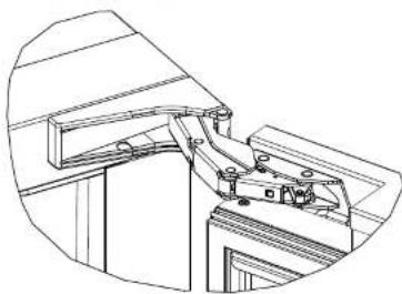
natural_image
Technical line drawing of a mechanical assembly with no visible text or symbols- Once cover is removed, slide hinge pin into hole as shown. Pin should slide into place, stopping the door at 90°; if the pin does not go into the hole shown, hold the door less than 90° open and try again.
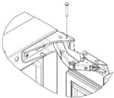
natural_image
Technical line drawing of a mechanical assembly with no visible text or symbols- To fully seat the pin, tap it lightly with a hammer.
- Carefully slide your unit back in place.
NOTICE
The pin can be removed to return the door swing back to its original 115° swing by tapping the pin out from the bottom of the hinge.
SAFETY • INSTALLATION & INTEGRATION • OPERATING INSTRUCTIONS • MAINTENANCE • SERVICE
Door Adjustments
DOOR ALIGNMENT AND ADJUSTMENT
Align and adjust the door if it is not level or is not sealing properly. If the door is not sealed, the unit may not cool properly, or excessive frost or condensation may form in the interior.
NOTICE
Properly aligned, the door's gasket should be firmly in contact with the cabinet all the way around the door (no gaps). Carefully examine the door's gasket to ensure that it is firmly in contact with the cabinet. Also make sure the door gasket is not pinched on the hinge side of the door.
CAUTION
Do not attempt to use the door to raise or pivot your unit. This would put excessive stress on the hinge system.
Alignment and Adjustment Procedure
- Open door and remove gasket near the hinges.

text_image
T-25 Torx Screw T-25 Torx ScrewREVERSING THE DOOR
-
Open door.
-
Remove top hinge cover by lifting top and bottom flaps and slide inwards. Repeat on bottom hinge.

natural_image
Technical line drawing of a mechanical assembly or bracket (no text or symbols)SAFETY • INSTALLATION & INTEGRATION • OPERATING INSTRUCTIONS • MAINTENANCE • SERVICE
- Using T-25 Torx bit loosen screw #1 and remove screw #2 on top and bottom hinge. Slide and remove the door from unit. Completely remove screw #1 on top and bottom.
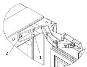
text_image
Technical diagram of a mechanical assembly with labeled parts 1 and 2-
Remove caps from screw heads on opposite side (2 on top and 2 on bottom). Using #2 Phillips bit remove the 4 underlying screws. Reinstall the screws and caps on the opposite side.
-
Partially install screw #1 in the outer most holes on top and bottom. Rotate door 180°, align hinge over screw #1 and slide/seat into position. Reinstall screw #2 on top and bottom. Tighten both screws and install hinge cover.
Align and adjust the door:
Align and adjust the door (see DOOR ALIGNMENT AND
SAFETY • INSTALLATION & INTEGRATION • OPERATING INSTRUCTIONS • MAINTENANCE • SERVICE
First Use
All U-Line controls are preset at the factory. Initial startup requires no adjustments.
NOTICE
U-Line recommends allowing the unit to run overnight before loading with product.
When plugged in, the unit will begin operating under the factory default setting. Follow the on screen prompt for language selection and temperature units.
To turn the unit off, press ⏻ and hold for 5 seconds and release. The display will show a countdown to switching the unit off.
To power your unit on, simply press ⏻ and the unit will immediately switch on.
SAFETY • INSTALLATION & INTEGRATION • OPERATING INSTRUCTIONS • MAINTENANCE • SERVICE
Control Operation

text_image
Up U-LINE Down Root 50°F Can be displayed in Celsius Zone Toggle Select Power U-Select LightingCONTROL FUNCTION GUIDE
| FUNCTION | COMMAND | DISPLAY/OPTIONS |
| OFF | Press 📍 and hold | Display will count down from 5 to off. |
| ON | Press 🔒 and release | Unit will come on immediately. |
| Select mode | Press 🔒 and release to scroll through the modes | Press 🔒 to select one of 5 modes (see table below). |
| Adjust temp | ||
| Adjust lighting | Press 🔒 to adjust lighting | Press 🔒 or 🔒 to set low, medium or high. |
| Light ON/OFF with door | Press 🔒 to have light on/off with door | Press 🔒 and release to scroll through timer settings. |
| Customer menu | Press 🔒 and hold for 5 seconds | Press 🔒 or 🔒 to scroll through menu. |


[1] [2] [3]
SAFETY • INSTALLATION & INTEGRATION • OPERATING INSTRUCTIONS • MAINTENANCE • SERVICE
U-SELECT® CONTROL
Digital Display
The 3000 Series units are controlled by a feature rich, advanced OLED display control unit. The control panel allows adjustment to temperature set point, access to Energy Saver Mode, internal temperature readings, and many other features.
ADJUSTING TEMPERATURE SETTINGS

text_image
Up U-LINE Down Root 50°F Can be displayed in Celsius Zone Toggle Select Power U-Select LightingEach zone has a series of Mode Settings with a default value for each setting. Each Mode Setting can be further customized by fine tuning the temperature set point. See the chart below for a description of each mode and mode temperature ranges. Mode selection will vary by model,
Mode Settings Chart
| Setting | Default °F (°C) | Range °F (°C) |
| Deli | 36 (2) | 34 - 40 (1 - 4) |
| Beverage/Drinks | 38 (3) | 34 - 65 (1 - 18) |
| Market/Fresh | 38 (3) | 34 - 40 (1 - 4) |
Food Storage Chart
| Mode | Food Types |
| Deli | Meats, Fish, Cheeses, Dairy, Butter, Garlic,Oils, Nuts, Condiments |
| Market/Fresh | Fruits, Vegetables, Berries, Lettuce |
| Pantry | Dry Goods, Breads, Baking Items, Spices,Seasonings |
| Root | Root Vegetables, Potatoes, Onions, Lemon,Lime, Melon, Peppers, Beans, Cucumber, CutVegetables |
QUICK CHILL
CAUTION
Quick chill is designed to quickly pull warm beverages and foods down to optimum storage temperature. It is important to only initiate quick chill modes when the Refrigerator or Wine Captain® have been fully loaded with warm product. Failure to follow this notice could result in food or beverages that are cooled to a point below optimum or frozen.
The following chart lists modes which include the quick chill feature and the time which quick chill will run.
| Mode | Run Time |
| Deli | 5 Hours |
| Beverage/Drinks | 4 Hours |
SAFETY • INSTALLATION & INTEGRATION • OPERATING INSTRUCTIONS • MAINTENANCE • SERVICE
Interior Lighting
Your U-Line 3000 Series unit uses a state of the art LED lighting system. The 3036 model dual zone's lighting can be independently controlled or set as a group.
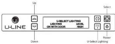
text_image
Up U-LINE Down U-SELECT LIGHTING LIGHTING LEVEL ON WITH DOOR HIGH Select Power U-Select Lighting- To begin, press 📋 to enter the lighting menu.
- Press ☐ or ☑ to cycle through each available brightness setting (Low, Medium or High).
- Press ☑ to cycle through each available timer setting. Selections include "On With Door", "On 3 Hours", "On 6 Hours", or "On 24 Hours".
- To exit, press 📄 or simply wait for the menu to time out.
Error Notification
The 3000 model series continuously monitors a series of inputs and parameters to ensure proper and efficient operation of your unit. Should the system detect a fault, an error notification will be displayed on the user interface. See below for a list of errors.
NOTE: Singe zone models will not use (L) left or (R) right zone indicators in error notification.
| ID | Description | Solution |
| No Comm | Unit lost communication to the display. | Disconnect and reconnect power to unit. Contact Customer Care if persistent. |
| (L) (R) Zone T Open | Left or right zone thermistor circuit open. | Contact Customer Care. |
| Amb Thrm Open | Ambient thermistor circuit open. | Contact Customer Care. |
| (L) (R) Zone T Short | Left or right zone thermistor circuit shorted. | Contact Customer Care. |
| Amb Thrm Short | Ambient thermistor circuit shorted. | Contact Customer Care. |
| (L) (R) Temp HI 6H+ | Left or right zone temperature +10° over set point for over 6 hours. | Verify door is closed and sealing. Contact Customer Care if persistent. |
| (L) (R) Temp HI 12H+ | Left or right zone temperature +10° over set point for over 12 hours. | Verify door is closed and sealing. Contact Customer Care if persistent. |
| (L) (R) Temp Lo 8H+ | Left or right zone temperature -10° under set point | Verify door is closed and sealing. Contact Customer Care if |
SAFETY • INSTALLATION & INTEGRATION • OPERATING INSTRUCTIONS • MAINTENANCE • SERVICE
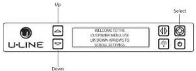
CUSTOMER MENU
The 3000 Series of U-Line undercounter refrigeration appliances contains a feature rich customer menu. The Customer Menu allows access to a series of advanced features including Energy Saver Mode, Sabbath Mode, actual temperature readings as well a method to restore factory defaults.
3000 Series - Customer Menu
text_image
U-LINE Up MELCOME TO THE CUSTOMER MENU AGE UP/DOWN ARRORS TO SCROLL SETTINGS Select Down- To access the Customer Menu hold 📄 for 5 seconds.
- Press ▲ or ▼ to scroll through available selections.
- Press 📷 to enter selected sub-menu.
- To exit Customer Menu, press ☑ to scroll to the bottom of the display and press 🔒 to select "Exit".
Actual Tomps
- Press ☐ or ☑ to scroll through available information.
- To return to the Customer Menu, press 📄.
Energy Saver Mode

text_image
Up Energy Saver Mode Indicator Select U-LINE ICE PRODUCTION (12m remaining) DownEnergy Saver Mode reduces overall energy consumption by altering user set point, differential, lighting and tone settings. When in Energy Saver Mode a small leaf icon will be displayed on the main screen.
- To enter Energy Saver Mode, first select Energy Saver from the Customer Menu.
- Press ☑ to select "Off" in the menu.
- Press
- Press ☐ or ☑ to change the selection from Off to On.
SAFETY • INSTALLATION & INTEGRATION • OPERATING INSTRUCTIONS • MAINTENANCE • SERVICE
Languages

text_image
Up U-LINE RETURN TO MENU LANGUAGES ENGLISH SelectThe U-Line 3000 Series of models supports a number of display languages including English, Spanish, French and German.
- To change display language select Languages from the Customer Menu.
- Press ☑ to select "English".
- Press 📋. "English" will begin to flash.
- Press ☐ or ☑ to cycle through the available languages.
- Press 🔒 to confirm your choice.
Sound Level
- Press ☐. The current setting will begin to flash.
- Press ☐ or ☑ to select a different level.
- Press 📋 to confirm your choice.
Fahrenheit/Celsius

text_image
U-LINE Up Return TO MENU FARENHEIT/CELSIUS DEGREES = °F Down SelectTemperature and set point information can be displayed in either Fahrenheit or Celsius.
To change from Fahrenheit to Celsius enter the Fahrenheit / Celsius Menu from within the Customer Menu.
- Press ☑ to select "Degrees".
- Press ☐. The selection will begin to flash.
SAFETY • INSTALLATION & INTEGRATION • OPERATING INSTRUCTIONS • MAINTENANCE • SERVICE
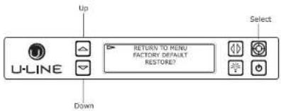
Factory Default
text_image
Up U-LINE Down RETURN TO MENU FACTORY DEFAULT RESTORE? SelectFactory Default will restore all settings to their factory default.
Help

text_image
Up U-LINE RETURN TO MENU HID Model 3045WC 1-800-779-2417 Down SelectTo access the Help Menu, select "Help" from the Customer Menu. Press 🔑 or 📋 to scroll through available information. The Help screen displays the following:
To access Factory Default:
- Press ☑ to select "Factory Default".
- Press
To restore settings to their factory default:
- Press ☑ to select "Restore?" and press 📋
- "Restore?" will change to "Restoring..." while settings are restored. When restoration is complete, "Restoring..." will return to "Restore?".
To exit Factory Default, press 🔒 to select "Return to Menu" and press 🔒 to confirm.
- Model.
• U-Line contact information. - Software version.
- Serial Number.
To exit the Help menu, press 🔒 to select "Return to Menu" and press 🔒 to confirm.
SAFETY • INSTALLATION & INTEGRATION • OPERATING INSTRUCTIONS • MAINTENANCE • SERVICE
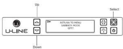
Sabbath Mode

text_image
Up U-LINE RETURN TO MENU SABBATH MODE OFF? Select DownThis unit offers a Sabbath mode for users who require this functionality during Sabbaths. Sabbath mode disables system responses to user initiated activities and all external functions, including lighting, display and audible alarms. The unit will still maintain internal temperatures and set points.
-
Press ☐ or ☑ to change "Off" to "On".
-
Press 📋 to confirm your selection.
The Display will fade out as the unit enters Sabbath Mode. Sabbath
Mode remains active until Ⓐ is quickly pressed and released.
To enable Sabbath Mode:
- Open the unit's door to activate the display.
- To access the Customer Menu, hold 📄 for 5 seconds.
- Press ☐ or ☑ to scroll through available selections.
SAFETY • INSTALLATION & INTEGRATION • OPERATING INSTRUCTIONS • MAINTENANCE • SERVICE
Airflow and Product Loading
NOTICE
The unit requires proper airflow to perform at its highest efficiency. Do not block the front grille, internal fans or vents at any time, or the unit will not perform as expected. When loading your unit, leave space between the internal fans or vents and product loaded. Anything blocking the required airflow/circulation will result in uneven temperature distribution in the cabinet and can also freeze product. Do not install the unit behind a door.
When properly loaded, your U-Line unit will store up to 123 (12 oz. [330 ml]) cans or 79 (12 oz. [330 ml]) bottles.
For optimal airflow, leave approximately two inches of space around the fan and one inch around the back wall and lower vents.
Door Removed For Illustration Purposes
SAFETY • INSTALLATION & INTEGRATION • OPERATING INSTRUCTIONS • MAINTENANCE • SERVICE
Interior Shelves
REMOVING AND INSTALLING GLASS SHELVES
Adjusting Interior Shelves
Models equipped with glass shelves have an adjustable mounting system. To adjust or simply remove shelves for cleaning, follow the instructions below.
- Remove all product from shelf.
- Coming from underneath the shelf, lift both the front and rear of the glass.
- Carefully slide shelf out of unit being careful not to scratch the interior liner.
- Installation is the reverse of removal.
Adjusting Shelf Height
Shelf height may be adjusted to accommodate a broad range of product. To alter your shelf spacing follow the instructions below.
- Remove the 4 Shelf clips from the shelf clip holes.
- Move shelf clips as a group to the desired shelf height.

CAUTION
Clips MUST be installed with the ribbed side down. Failure to do so may result in shelf or unit damage.
NOTICE
All 4 shelf clips for each shelf must be installed at the same height for shelf stability.
- Reinstall shelf.
Cleaning Shelves
Shelves may be cleaned in a soapy warm water solution. A general household disinfectant may be used if necessary. Be sure to completely dry your shelf before reinstalling.
SAFETY • INSTALLATION & INTEGRATION • OPERATING INSTRUCTIONS • MAINTENANCE • SERVICE
Refrigerator Bins - Crisper
REFRIGERATOR BIN INSTALLATION & REMOVAL
Refrigerator bins are easily removed for cleaning and sanitizing. To remove your bin follow the instructions below.
text_image
Technical diagram showing a mechanical assembly with labeled components and directional arrows indicating movement or force.- Fully extend the bin you wish to remove from the cabinet.
- Lift the front lip of the bin and raise the bin off the racks.
- Lift the rear of the bin off its seat on the rack.
- Pull the bin up and away from the racks.
Cleaning
Bins may be cleaned in a soapy warm water solution. A general household disinfectant, safe for plastics, may be used if necessary. Be sure to completely dry your bin before reinstalling.
NOTICE
Bins are NOT dishwasher safe.
SAFETY • INSTALLATION & INTEGRATION • OPERATING INSTRUCTIONS • MAINTENANCE • SERVICE
Cleaning
EXTERIOR CLEANING
Stainless Models
Stainless door panels and handles can discolor when exposed to chlorine gas, pool chemicals, saltwater or cleaners with bleach.
Keep your stainless unit looking new by cleaning with a good quality all-in-one stainless steel cleaner and polish monthly. For best results use Claire® Stainless Steel Polish and Cleaner. Comparable products are acceptable. Frequent cleaning will remove surface contamination that could lead to rust. Some installations may require cleaning weekly.
Do not clean with steel wool pads.
Do not use stainless steel cleaners or polishes on any glass surfaces.
Clean any glass surfaces with a non-chlorine glass cleaner.
Do not use cleaners not specifically intended for stainless steel on stainless steel surfaces (this includes glass, tile and counter cleaners).
Integrated Models
To clean integrated panels, use household cleaner per the cabinet manufacturer's recommendation.
INTERIOR CLEANING
Disconnect power to the unit.
Clean the interior and all removed components using a mild nonabrasive detergent and warm water solution applied with a soft sponge or non-abrasive cloth.
Rinse the interior using a soft sponge and clean water.
Do not use any solvent-based or abrasive
cleaners. These types of cleaners may transfer taste to the interior products and damage or discolor the lining.
DEFROSTING
Under normal conditions this unit does not require manual defrosting. Minor frost on the rear wall or visible through the evaporator plate vents is normal and will melt during each off cycle.
If there is excessive build-up of 1/4" (6 mm) or more, manually defrost the unit.
SAFETY • INSTALLATION & INTEGRATION • OPERATING INSTRUCTIONS • MAINTENANCE • SERVICE
NOTICE
The drain pan was not designed to capture the water created when manually defrosting. To prevent water from overflowing the drain pan and possibly damaging water sensitive flooring, the unit must be removed from cabinetry.
To defrost:
- Disconnect power to the unit.
- Remove all products from the interior.
- Prop the door in an open position (2 in. [50 mm] minimum).
- Allow the frost to melt naturally.
- After the frost melts completely clean the interior and all removed components. (See INTERIOR CLEANING).
- When the interior is dry, reconnect power and turn unit on.
SAFETY • INSTALLATION & INTEGRATION • OPERATING INSTRUCTIONS • MAINTENANCE • SERVICE
Cleaning Condenser
INTERVAL - EVERY SIX MONTHS
To maintain operational efficiency, keep the front grille (plinth strip/base fascia) free of dust and lint, and clean the condenser when necessary. Depending on environmental conditions, more or less frequent cleaning may be necessary.
WARNING
Disconnect electric current to the unit before cleaning the condenser.
NOTICE
DO NOT use any type of cleaner on the condenser unit. Condenser may be cleaned using a vacuum, soft brush or compressed air.
- Remove the grille (plinth strip/base fascia). (See GRILLE-PLINTH INSTALLATION).
- Clean the condenser coil using a soft brush or vacuum cleaner.
- Install the grille (plinth strip/base fascia).
SAFETY • INSTALLATION & INTEGRATION • OPERATING INSTRUCTIONS • MAINTENANCE • SERVICE
Extended Non-Use
VACATION/HOLIDAY, PROLONGED SHUTDOWN
The following steps are recommended for periods of extended non-use:
- Remove all consumable content from the unit.
- Disconnect the power cord from its outlet/socket and leave it disconnected until the unit is returned to service.
- If ice is on the evaporator, allow ice to thaw naturally.
- Clean and dry the interior of the unit. Ensure all water has been removed from the unit.
- The door must remain open to prevent formation of mold and mildew. Open door a minimum of 2° (50 mm) to provide the necessary ventilation.
WINTERIZATION
If the unit will be exposed to temperatures of 40^ F ( 5^ C) or less, the steps above must be followed.
For questions regarding winterization, please
SAFETY • INSTALLATION & INTEGRATION • OPERATING INSTRUCTIONS • MAINTENANCE • SERVICE
Troubleshooting
BEFORE CALLING FOR SERVICE
If you think your U-Line product is malfunctioning, read the CONTROL OPERATION section to clearly understand the function of the control.
If the problem persists, read the NORMAL OPERATING SOUNDS and TROUBLESHOOTING GUIDE sections below to help you quickly identify common problems and possible causes and remedies. Most often, this will resolve the problem without the need to call for service.
IF SERVICE IS REQUIRED
If you do not understand a troubleshooting remedy, or your product needs service, contact U-Line Corporation directly at +1.800.779.2547.
When you call, you will need your product Model and Serial Numbers. This information appears on the Model and Serial number plate located on the interior of your product or can be accessed through "Help" in the Customer Menu.
All models incorporate rigid foam insulated cabinets to provide high thermal efficiency and maximum sound
- Compressor: The compressor makes a hum or pulsing sound that may be heard when it operates.
- Evaporator: Refrigerant flowing through an evaporator may sound like boiling liquid.
- Condenser Fan: Air moving through a condenser may be heard.
- Automatic Defrost Drain Pan: Water may be heard dripping or running into the drain pan when the unit is in the defrost cycle.
- Solenoid Valves: An occasional clicking sound may be heard as solenoid valves are operated.
TROUBLESHOOTING GUIDE

DANGER
ELECTROCUTION HAZARD. Never attempt to repair or perform maintenance on the unit before disconnecting the main electrical power.
Troubleshooting - What to check when problems occur:
SAFETY • INSTALLATION & INTEGRATION • OPERATING INSTRUCTIONS • MAINTENANCE • SERVICE
| Problem | Possible Cause and Remedy |
| Digital Display Functions, But Unit Does Not Cool. | Ensure the unit is not in "Showroom Mode." Momentarily unplug or interrupt power supply to the unit. |
| Digital Display Shows an Error. | "Door" indicates the door may be opened too long. Ensure the door is closing properly. For other error codes contact U-Line Customer Service. |
| Product Is Freezing. | Because product in contact with the rear wall may freeze, ensure no product is touching the rear wall.Adjust the temperature to a warmer set point. |
| Product Is Not Cold Enough. | Air temperature does not indicate product temperature.Adjust the temperature to a cooler set point.Ensure unit is not located in excessive ambient temperatures or in direct sunlight.Ensure the door is closing and sealing properly.Ensure nothing is blocking the front grille, found at the bottom of the unit.Ensure the condenser coil is clean and free of any dirt or lint build-up. |
ERROR NOTIFICATION
The 3000 model series continuously monitors a series of inputs and parameters to ensure proper and efficient operation of your unit. Should the system detect a fault, an error notification will be displayed on the user interface. See below for a list of errors.
NOTE: Single zone models will not use (L) left or (R) right
| ID | Description | Solution |
| (L) (R) Temp Hi 6H+ | Left or right zone temperature +10° over set point for over 6 hours. | Verify door is closed and sealing. Contact Customer Care if persistent. |
| (L) (R) Temp Hi 12H+ | Left or right zone temperature +10° over set point for over 12 hours. | Verify door is closed and sealing. Contact Customer Care if persistent. |
| (L) (R) Temp Lo 6H+ | Left or right zone temperature -10° under set point for over 6 hours. | Verify door is closed and sealing. Contact Customer Care if persistent. |
| (L) (R) Temp Lo 12H+ | Left or right zone temperature -10° under set point for over 12 hours. | Verify door is closed and sealing. Contact Customer Care if persistent. |
| (L) (R) Door Open 5M | Left or right door switch open for more then 5 minutes. | Verify door is closed and sealing. Contact Customer Care if persistent. |
CHECKING PRODUCT TEMPERATURE

SAFETY • INSTALLATION & INTEGRATION • OPERATING INSTRUCTIONS • MAINTENANCE • SERVICE
- After 24 hours, check the temperature of the water. If required, adjust the temperature control in a small increment (see CONTROL OPERATION).
Causes which affect the internal temperatures of the cabinet include:
• Temperature setting.
• Ambient temperature where installed.
• Installation in direct sunlight or near a heat source.
- The number of door openings and the time the door is open.
- The time the internal light is illuminated. (This mainly affects product on the top rack or shelf.)
• Obstruction of front grille or condenser.
SAFETY • INSTALLATION & INTEGRATION • OPERATING INSTRUCTIONS • MAINTENANCE • SERVICE
U-Line Corporation (U-Line) Limited Warranty
One Year Limited Warranty
For one year from the date of original purchase, this U-Line product warranty covers all parts and labor to repair or replace any part of the product that proves to be defective in materials or workmanship. For products installed and used for normal residential use, material cosmetic defects are included in this warranty, with coverage limited to 60 days from the date of original purchase. All service provided by U-Line under the above warranty must be performed by U-Line factory authorized service, unless otherwise specified by U-Line. Service provided during normal business hours.
Available Second Year Limited Warranty
Beyond the standard one year warranty outlined above, U-Line offers an extension of the one year warranty coverage for an additional second year from the date of purchase, free of charge. To take advantage of this second year warranty, you must register your product with U-Line within two months from the date of purchase at u-line.com providing proof of purchase.
Five Year Sealed System Limited Warranty
For five years from the date of original purchase, U-Line will repair or replace the following parts, labor not included, that prove to be defective in materials or workmanship: compressor, condenser, evaporator, drier, and all connecting tubing. All service provided by U-Line under the above warranty must be performed by U-Line factory authorized service, unless otherwise specified by U-Line. Service provided during normal business hours.
Terms
These warranties apply only to products installed in any one of the fifty states of the United States, the District of Columbia, or the ten provinces of Canada. The warranties do not cover any parts or labor to correct any defect caused by negligence, accident or improper use, maintenance, installation, service, repair, acts of God, fire, flood or other natural disasters. The product must be installed, operated, and maintained in accordance with the U-Line User Guide.
The remedies described above for each warranty are the only ones that U-Line will provide, either under these warranties or under any warranty arising by operation of law. U-Line will not be responsible for any consequential or incidental damages arising from the breach of these warranties or any other warranty, whether express, implied, or statutory. Some states do not allow the exclusion or limitation of incidental or consequential damages, so the above limitation or exclusion may not apply to you. These warranties give you specific legal rights, and you may also have other rights which vary from state to state.
Any warranty that may be implied in connection with your purchase or use of the product, including any warranty of merchantability or any warranty fit for a particular purpose is limited to the duration of these warranties, and only extends to five years in duration for the parts described in the context related to the five years limited warranty above. Some states do not allow limitations on how long an implied warranty
SAFETY • INSTALLATION & INTEGRATION • OPERATING INSTRUCTIONS • MAINTENANCE • SERVICE
Wire Diagram

text_image
OVERLOAD D HOT NEUTRAL RELAY CREY EMBRACO COMPRESSOR 115 VOLT 220-240 VOLT PLUG OVERLOAD HOT LIGHT BLUE GROUND: GREEN W YELLOW GREEN W YELLOW NEUTRAL DAIR BLUE RELAY BROWN BLUE CAP EMBRACO COMPRESSOR 220-240 VOLT NEUTRAL: WHITE (115V) DAIR BLUE (220-240V) TO COMPRESSIONS 115 VOLT PLUG GROUNDS: GREEN & GREEN W YELLOW HOT: BLACK (115V) BROWN (220-240V) NEUTRAL WHITE (115V) DAIR BLUE (220-240V) TO COMPRESSIONS C POWER CORD ASSEMBLYSAFETY • INSTALLATION & INTEGRATION • OPERATING INSTRUCTIONS • MAINTENANCE • SERVICE
Product Liability
Field service technicians are authorized to make an initial assessment in the event of reported damages. If there are any questions about the process involved, the technician should call U-Line for further explanation.
While inspecting for defects or installation issues, photos should be taken to document any damages or issues found.
During the assessment, if the service technician is able to find the source of the damage and it can be resolved by replacement of a part, the servicer is authorized to replace the part in question. The part that caused the damage must be returned to U-Line in its entirety. The part must be clearly labeled with the serial number of the unit it was removed from, the date, and the servicer who removed the part.
If the service technician determines the damage is the result of installation issues (water connection/drain, etc.), the consumer would be notified and the issues shall be resolved at the direction of the consumer.
If damage is evident and the service technician is unable to find the source, U-Line must be contacted at 1-800-799-2547 for further direction
SAFETY • INSTALLATION & INTEGRATION • OPERATING INSTRUCTIONS • MAINTENANCE • SERVICE
Warranty Claims
The following information defines the parameters for filing a warranty claim:
- Valid serial number needed
- Valid model number needed
- Narda (or equivalent) form or submitted online at www.u-line.com
- 60 day submittal deadline from date of completed service
• Only one repair or unit per warranty claim - Refrigerant should be labeled and included on the labor submittal
- Door and water level adjustments are covered 30 days from install date.
Serial Number Requirements:
14 30911 12 XXXX
warranty status. We also accept the following information to verify warranty status:
• New Construction Occupancy Documents
- Closing Paperwork
• Final Billing - Remodel
Noting all of the following on the warranty claim will be considered proof of purchase, hard copy will not be required:
• Name of the selling Dealer
• Date of purchase/installation
• Order or Invoice number (if available)
• Description of document reviewed (i.e. store receipt, closing paperwork, etc)
Parts and labor claims are paid separately. Indicate part numbers and description for parts used in the warranty repair. Include the purchase invoice and name of the parts supplier used to procure the parts.
SAFETY • INSTALLATION & INTEGRATION • OPERATING INSTRUCTIONS • MAINTENANCE • SERVICE
Parts
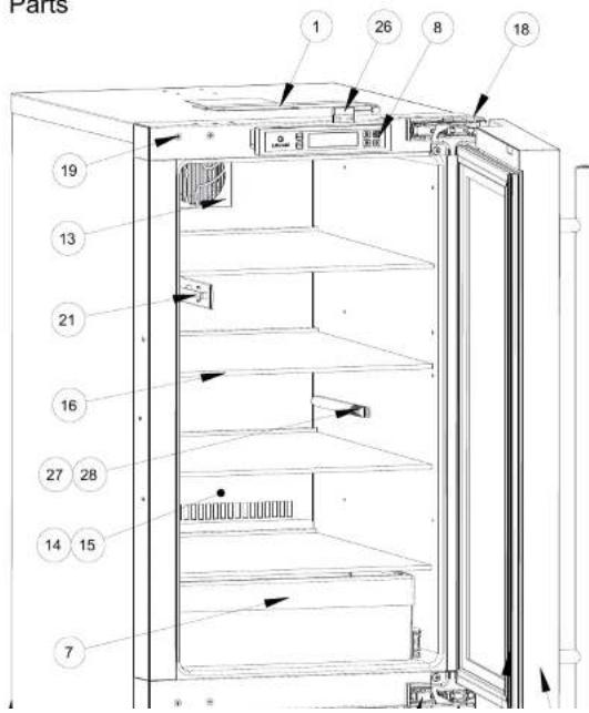
text_image
Parts 1 26 8 18 19 13 21 16 27 28 14 15 7U-3018RGLS-00B
| Item | Description | U-Line P/N |
| 1 | Anti tip bracket w/screws | 80-54012-00 |
| 2 | Backpanel | 80-54175-00 |
| 3 | Compressor electricals only | 80-54149-00 |
| 4 | Compressor w/electricals | 80-54150-00 |
| 5 | Condenser | 80-54022-00 |
| 6 | Condenser fan w/screws | 80-54014-00 |
| 7 | Crisper | 80-54025-00 |
| 8 | Display module | 80-54032-00 |
| 9 | Door assembly w/ hinges | 80-54154-00 |
| 10 | Door gasket | 80-54003-00 |
| 11 | Drain pan w/double sided tape | 80-54002-00 |
| 12 | Drier | 80-54055-00 |
| 13 | Evap fan w/cover and screws | 80-54151-00 |
| 14 | Evaporator | 80-54152-00 |
| 15 | Evaporator cover | 80-54021-00 |
| 16 | Glass shelf(1) w/clips | 80-54015-00 |
| 17 | Grille w/screws | 80-54031-00 |
| 18 | Hinge covers(2 pcs) | 80-54001-00 |
| 19 | Hinge mounting hole covers | 80-54024-00 |
| 20 | Hinges(2) w/screws and covers | 80-54013-00 |
| 21 | LED light strip and cover assy | 80-54000-00 |
| 22 | Leg Levelers (4) | 80-54019-00 |
| 23 | Main board (no wires or case) | 80-54008-00 |
| 24 | Packaging | 80-54145-00 |
| 25 | Dinner cord | 80-54171-00 |
SAFETY • INSTALLATION & INTEGRATION • OPERATING INSTRUCTIONS • MAINTENANCE • SERVICE
Ordering Replacement Parts
If you have a purchasing account, please utilize our service website to order parts.
Orders may also be placed by Fax or phone. See our contact information below:
www.U-LineService.com (with service login)
FAX Number: +1.414.354.5696
Phone Number: +1.800.779.2547
NOTICE
Use only genuine U-Line replacement parts. The use of non-U-Line parts can reduce speed of ice production, cause water to overflow from ice maker mold, damage the unit, and void the warranty.
Warranty parts will be shipped at no charge after U-Line confirms warranty status. Please provide the model, serial number, part number and part description. Some parts will require color or voltage information.
If U-Line requires the return of original parts, we will inform you when the parts order is taken. This requirement will be noted on your packing list. A prepaid
SAFETY · INSTALLATION & INTEGRATION · OPERATING INSTRUCTIONS · MAINTENANCE · SERVICE
System Diagnosis Guide
| System Condition | Suction Pressure | Suction Line | Compressor Discharge | Condenser | Capillary Tube | Evaporator | Wattage |
| Normal | Normal | Slightly below room temperature | Very hot | Very hot | Warm | Cold | Normal |
| Overcharge | Higher than normal | Very cold may frost heavily | Slightly warm to hot | Hot to warm | Cool | Cold | Higher than normal |
| Undercharge | Lower than normal | Warm-near room temperature | Hot | Warm | Warm | Extremely cold near inlet - Outlet below room temperature | Lower than normal |
| Partial Restriction | Somewhat lower than normal vacuum | Warm - near room temperature | Very hot | Top passes warm - Lower passes cool (near room temperature) due to liquid | Room temperature (cool) or colder | Extremely cold near inlet - Outlet below room temperature backing up | Lower than normal |
| Complete Restriction | In deep vacuum | Room temperature (cool) | Room temperature (cool) | Room temperature (cool) | Room temperature (cool) | No refrigeration | Lower than normal |
| No Gas | 0 PSIG to 25° | Room temperature (cool) | Cool to hot | Room temperature (cool) | Room temperature (cool) | No refrigeration | Lower than normal |
SAFETY • INSTALLATION & INTEGRATION • OPERATING INSTRUCTIONS • MAINTENANCE • SERVICE
Compressor Specifications

DANGER
Electrocution can cause death or serious injury. Burns from hot or cold surfaces can cause serious injury. Take precautions when servicing this unit.
Disconnect the power source.
Do not stand in standing water when working around electrical appliances.
Make sure the surfaces you touch are not hot or frozen.
Do not touch a bare circuit board unless you are wearing an anti-static wrist strap that is grounded to an electrical ground or grounded water pipe.
Handle circuit boards carefully and avoid touching components.
To measure the start winding resistance, measure across
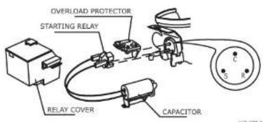
text_image
OVERLOAD PROTECTOR STARTING RELAY RELAY COVER CAPACITOR| EMX20CLC | |
| Refrigerant | R600a |
| Voltage | 115 - 127 VAC |
| Frequency | 60 Hz |
| Run Cap | 12μF/165 VAC |
| Start Winding | 6.7 Ohm at 77°F |
| Run Winding | 12.6 Ohm at 77°F |
| LRA | 3.7 A |
| FLA | 0.5 A |
| Starting Device | 8EA14C |
| Overload | 4TM142RFBYY-53 |
* All resistance readings are ±10%
SAFETY • INSTALLATION & INTEGRATION • OPERATING INSTRUCTIONS • MAINTENANCE • SERVICE
Troubleshooting - Extended
SPECIFIC ERRORS AND ISSUES
The technically advanced diagnostic capabilities of the electronic controls utilized on the 3000 series units allows for easy and thorough trouble shooting.
Navigation of the control is the key and is explained in the CONTROL OPERATION section of the manual, along with control button layout, control function descriptions, a service mode menu and service menu selection explanations.
Verification of temperature and thermistor performance can be identified by directly viewing actual temperature readings in the service mode.
Component failure issues can be identified through service mode menu selection, "Relay Toggle" Individual components can be switched on and off to check for both proper function of a specific component and also delivery of supply voltage to the components through the relays and DC outputs located on the relay/power board.
Included in this section is some diagnostic tips and as always, if additional help is required please contact the U-Line Corp, "Customer Care Facility" at +1.800.779.2547 for assistance.
SAFETY • INSTALLATION & INTEGRATION • OPERATING INSTRUCTIONS • MAINTENANCE • SERVICE
TROUBLESHOOTING GUIDE
| Concern | Potential Causes | Suggested Remedy |
| Not Cooling | Compressor overheating | Verify proper air flow through condenser (Refer to Airflow/General Information Section). |
| Confirm condenser fan operation (Refer to Airflow/General Information Section). | ||
| Confirm proper compressor operating voltage (Refer to Toggle/ Compressor Information Section). | ||
| Compressor not operating | Confirm proper compressor operating voltage (Refer to Toggle/ Compressor Information Section to initiate power to the compressor). | |
| Test overload and relay, replace as needed. | ||
| Compressor operating - no cooling | Refer to System Diagnosis Guide. | |
| Evaporator fan not operating | Refer to Convection Cooling Section. | |
| Frozen Product | Ensure proper use of Quick Chill mode. | Refer to Control Operation Section. |
| Control set too cold | Refer to Adjusting Temperature Settings Section | |
| Review logged error codes | Refer to Fault System Diagnosis Guide. | |
| Thermistor failure | Refer to Thermistor Failure Section | |
| Frost Buildup Inside Unit | Door Ajar or Restricted from Closing | Check door clearance to adjoining cabinetry. Check distribution of product in unit. |
| Evaporator fan not operating | Use #19, Component Testing In Service Mode. | |
| Thermistor failure | Refer to Thermistor Failure Section. | |
| Display Not Working | Unit placed in Sabbath mode? | Refer to Sabbath Mode Section. |
| Display unplugged | Verify that both ends of the display wiring are firmly connected. | |
| Display wiring broken or damaged | Perform continuity test of wiring and replace as needed. | |
| Internal Lights Not Working | Control Setting | Refer to the Interior Lighting Section. |
| Unit set to Sabbath Mode. Refer to the Sabbath Mode Section. | ||
| Door switch misaligned or defective | Refer to Reed Switch Section. | |
| Noisy | Refrigeration tubing touching cabinet | Carefully reposition tubing. |
| Fan blade obstruction (wiring, foam insulation, packaging material) | Remove obstruction. |
SAFETY • INSTALLATION & INTEGRATION • OPERATING INSTRUCTIONS • MAINTENANCE • SERVICE
MAIN CONTROL
The main control board is very robust and is rarely the cause of system issues. It is important to fully diagnose the board for any suspected failures before attempting to remove the board for replacement or service. Follow the guidelines below to fully test and diagnose the main control.
Power Fault
If the unit does not (or seems to not) power on, follow the flow chart below to help diagnose the issue. Before beginning it is important to first verify the unit is not simply set to sabbath mode.

flowchart
graph TD
    A["Check Voltage At Wall Outlet"] -->|Voltage| B["Verify Voltage At Main Control Voltage Input"]
    B -->|Voltage| C["Check Fuse F1 For Continuity"]
    C -->|Continuity| D["End"]
    A -->|No Voltage| E["Alert Customer Of Power Failure"]
    B -->|No Voltage| F["Replace Power Cord"]
    C -->|No Continuity| G["Replace Fuse"]
Testing The Main Control
If the main control is suspected of being faulty, the following procedure should be performed to verify main control for functionality.
Relay & DC Outputs
One of the primary functions of the main control is to operate the multiple relay and DC outputs during each cycle. Verify proper operation of these relays using the following procedure.
- Enter "Relay Toggle" through the service menu.
NOTICE
Frequently toggling the compressor relay could force the compressor into overload. The compressor will automatically deactivate during an overload and will remain deactivated until the overload switch cools. This could take some time. It is important to allow the compressor at least 5 minutes off time between relay cycles.
- Toggle the relay. Its related component should activate / deactivate with the switching of the relay. If it does not, see "Component Testing."
Innuite
SAFETY • INSTALLATION & INTEGRATION • OPERATING INSTRUCTIONS • MAINTENANCE • SERVICE
Other Suspected Main Control Faults
If other components have been ruled out as being faulty but the unit continues to have operating issues, it is most likely due to a configuration error. Configuration errors can be cleared by restoring the unit to its factory default setting. Factory defaults may be restored through the service menu.
NOTE: If the unit is set to sabbath mode the evaporator fan will no longer respond to the state of the door switch.
In order to operate efficiently the evaporator fan blade and vents should be unobstructed and free of any dust buildup.
CAUTION
Precautions must be taken while working with live electrical equipment. Be sure to follow proper safety procedures while performing tests on live systems.
CONVECTION COOLING
All 3000 series units are equipped with an advanced convection cooling system. Convection cooling stabilizes cabinet temperature, cools product faster and increases energy efficiency.
Evaporator Fan
The evaporator fan is responsible for circulating warm air from the refrigeration zone, past the evaporator and back into the refrigerated zone.
SAFETY • INSTALLATION & INTEGRATION • OPERATING INSTRUCTIONS • MAINTENANCE • SERVICE
FAULT SYSTEM DIAGNOSIS GUIDE
| Error | Solution 1 | Solution 2 | Solution 3 |
| No Comm | Inspect Customer UI and Data Cable (if defective replace entire door) | ||
| Zone T Open | Inspect zone thermistor connection. Replace if necessary. | Inspect main control wire harness for splits or breaks. Repair split or cut cabling. | |
| Evap T Open | Inspect evaporator thermistor connection. Replace if necessary. | Inspect main control wire harness for splits or breaks. Repair split or cut cabling. | |
| Amb Thrm Open | Inspect ambient thermistor connection. Replace if necessary. | Inspect main control wire harness for splits or breaks. Repair split or cut cabling. | |
| Zone T Short | Inspect thermistor cable for pinch points or damage. Replace if necessary. | Inspect wire harness from main control board for pinch points or damage. Repair split or pinched cabling. | |
| Evap T Short | Inspect thermistor cable for pinch points or damage. Replace if necessary. | Inspect wire harness from main control board for pinch points or damage. Repair split or pinched cabling. | |
| Amb Thrm Short | Inspect thermistor cable for pinch points or damage. Replace if necessary. | Inspect wire harness from main control board for pinch points or damage. Repair split or pinched cabling. | |
| Temp Hi 6H+ | If excessive frost is also noted, inspect door and door gasket for proper seal and alignment. | Inspect evaporator fan for proper operation. | Inspect refrigeration system. Reference the System Diagnosis Guide. |
| Temp Hi 12H+ | If excessive frost is also noted, inspect door and door gasket for proper seal and alignment. | Inspect evaporator fan for proper operation. | Inspect refrigeration system. Reference the System Diagnosis Guide. |
| Temp Lo 6H+ | Inspect main control for proper relay operation. | Inspect refrigeration system. Reference the System Diagnosis Guide. | |
| Temp Lo 12H+ | Inspect main control for proper relay operation. | Inspect refrigeration system. Reference the System Diagnosis Guide. |
SAFETY • INSTALLATION & INTEGRATION • OPERATING INSTRUCTIONS • MAINTENANCE • SERVICE
THERMISTORS
Thermistors are used for various temperature readings. Thermistors provide reliable temperature readings using a resistance which varies based on surrounding temperatures. If a faulty thermistor is suspected it may be tested using an accurate ohmmeter. In an ice water bath (32°F) resistance should measure 16.1 kilohms.
5K OHMS @ 77°
16.1K OHMS - 32°F ambient
THERMISTOR FAILURE
Limp Mode Data Table
If the zone thermistor falls, the unit will continue to operate in a timed limp mode which varies by model. The unit will otherwise operate normally. The error will be displayed in the error log.
REED SWITCH
A reed switch is used to monitor door state. When the door is closed magnetic force pulls the reed to its contact and closes the circuit which turns the light and display off. When the door is open the reed pulls away from the contact and opens the circuit. If the door is left open for longer than 5 minutes, the switch will trigger an error code and set an audible warning.

text_image
Magnet Away From Switch (Door Open) (Switch Open)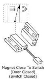
SAFETY • INSTALLATION & INTEGRATION • OPERATING INSTRUCTIONS • MAINTENANCE • SERVICE
Control Operation - Service
TO ENTER THE MAIN SERVICE MENU
PRESS AND HOLD FOR 5 SECONDS

AND

TO GO TO NEXT SUB-MENU ITEM
YOU MUST ARROW UP TO "RETURN TO MENU"
TOUCH AND RELEASE TO RETURN TO THE MAIN MENU
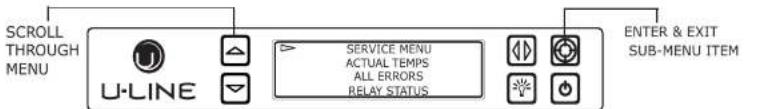
text_image
SCROLL THROUGH MENU U-LINE SERVICE MENU ACTUAL TEMPS ALL ERRORS RELAY STATUS ENTER & EXIT SUB-MENU ITEM| ACTUAL TEMPS | SHOWS TEMPERATURES WITHOUT OFFSETS. EACH ZONE HAS AN EVAP AND AIR THERMISTOR. EACH UNIT HAS AN AMBIENT THERMISTOR | RETURN TO MENUACTUAL TEMPSLEFT ZONE = 52°LEFT EWP = 52° |
| ALL ERRORS | DISPLAYS THE NUMBER OF TIMES AN ERROR HAS OCCURRED SCROLL TO THE END TO ERASE THE ERROR CODES | RETURN TO MENALL ERRORSNO COMM 3L ZONE TO OPEN 9 |
| RELAY STATUS | DISPLAYS THE CURRENT STATUS OF THE RELAYS ON THE BOARD (not all relays are used on all models) | RETURN TO MENRELAY STATUSMULL COND DEF LUVOFF 00" - 017" 00" |
| RELAY TOGGLE | ALLOWS THE RELAYS TO BE TOG GLED ON/OFF TO CHECK RELAY & COMPONENT YOU CAN TURN ON MULTIPLE RELAYS TO CHECK A ZONE, (COMP FAN ETC) | RETURN TO MENURELAY TOGGLEFULL OFFCOND OFF |
| INPUT STATUS | DISPLAYS DOOR SWITCH STATE, TEST INPUT, AND USB STATE | RETURN TO MENUINPUT STATUSLEFT DOOR CLOSEDRIGHT DOOR OPEN |
| OUTPUTS | MONITORS THE STATE OF DC OUTPUTS(evap & condenser fans 0 - 100% and lighting off - low - med - high) | RETURN TO MENOUPTPUTSL EXP FAN = 2%B EXP FIN = 0% |
| OFFSETS | OFFSETS ARE USED TO ADJUST OR CORRECT THERMISTOR READINGSCORRECTED VALUES MAY BE VIEWED THROUGH THE CUSTOMER MENU | RETURN TO MENOUPTSEPSRIGHT ZONE = -19°CRIGHT EWP = -17°C |
| SELF TEST | SELF TEST IS USED TO DIAGNOSE THE BOARD IF NO ERRORS ARE PRESENT "NO ERRORS" WILL BE DISPLAYED, THE MAIN BOARD IS FUNCTIONING PROPERLY | RETURN TO MENUSELF TESTNO ERRORS |
| DIFFERENTIALS | DIFFERENTIALS ARE USED TO DETERMINE AT WHAT TEMPERATURE THE UNIT CYCLES. "0" SETTING IS +/- 2° DIFFERENTIAL | RETURN TO MENODIFFERDITALSL LEFT = -16°CRIGHT = -16°C |
| EVAP FAN | THIS MENU IS USED TO SET THE DURATION THE EVAPORATOR FAN WILL RUN AFTER THE COMPRESSOR CYCLES OFF | RETURN TO MENEOVAP FANEVAP FAN ON = 1EVAP FAN OFF = 30 |
SAFETY • INSTALLATION & INTEGRATION • OPERATING INSTRUCTIONS • MAINTENANCE • SERVICE
SERVICE MENU
In addition to a feature rich customer menu, the 3000 series also offers a service menu with the ability to fine tune and monitor unit operation.
To initiate the Service menu hold both 🔒 and 📄 for 5 seconds.
Actual Temps
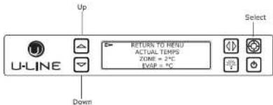
text_image
U-LINE Up Down RETURN TO MENU ACTUAL TEMPS ZONE = 2°C RISP = 5°C SelectThe Actual Temp option in the service menu will display raw thermistor readings without calculating offsets.
-
Press ☑ to select "Actual Temps".
-
Press
-
Use ☑ and ☑ to scroll through available thermistor readings.
The All Errors option keeps record of any system errors. When an error occurs it is recorded to all errors. The number next to the error indicates the number of recorded instances. Errors in the log may not be currently active. The error log memory is non volatile and is persistent should power be lost and restored to the unit. See below for a list of logged errors and their respective descriptions.
| ID | Description | Solution |
| No Comm | Unit lost communication to the display. | Unplug the communication cable from the user interface. Check the black to red conductors looking for 5 VDC. If voltage is present replace the user interface. If no voltage is present check for 5 VDC at the main board where the communication cable plugs onto the pins for the red and black conductors. If 5 VDC is not present replace the main control board. If 5 VDC is present replace the communication cable. |
| Zone T Open | Zone thermistor circuit open. | Check thermistor connection to harness for moisture or corrosion. Also check connection where thermistor harness attaches to main board. If connections are valid replace the thermistor. |
| Evap T Open | Evaporator thermistor circuit open. | Check thermistor connection to harness for moisture or corrosion. Also check connection where thermistor harness attaches to main board. If connections are valid replace the thermistor. |
| Amb | Ambient | Check thermistor connection to |
SAFETY • INSTALLATION & INTEGRATION • OPERATING INSTRUCTIONS • MAINTENANCE • SERVICE
| ID | Description | Solution |
| Amb Thrm Short | Ambient thermistor circuit shorted. | Check thermistor connection to harness for moisture or corrosion. Also check connection where thermistor harness attaches to main board. If connections are valid replace the thermistor. |
| Temp Hi 6H+ | Zone temperature +10°F over set point for over 6 hours. | Is condenser coil clean? Is condenser fan operating? Check zone thermistor for correct resistance. Verify thermistor connections are clean and intact. Check zone valve operation. Sealed system issue? |
| Temp Hi 12H+ | Zone temperature +10°F over set point for over 12 hours. | Is condenser coil clean? Is condenser fan operating? Check zone thermistor for correct resistance. Verify thermistor connections are clean and intact. Check zone valve operation. Sealed system issue? |
| Temp Lo 6H+ | Zone temperature -10°F under set point for over 6 hours. | Verify thermistor connections are clean and dry. Verify thermistor resistance. Verify correct operation of zone valve. |
| Temp Lo 12H+ | Zone temperature -10°F under set point for over 12 hours. | Verify thermistor connections are clean and dry. Verify thermistor resistance. Verify correct operation of zone valve. |
| Door Open 5M | Door switch open for more then 5 minutes. | Check door switch magnet reed switch alignment when door is in closed position. Check reed switch connection at the harness and the main board. |
To access All Errors follow the steps below.
Relay Status

text_image
Up U-LINE RETURN TO HENU RELAY STATUS... MULL COND DEF LUV OFF OFF OFF OFF Select DownRelay status displays the current state of each relay. While all available relays are displayed, only a portion are used.
| ID | Description | Availability |
| Mull | Mullion Heater | Not Used |
| Cond | Condenser Fan | Not Used |
| Def | Defrost Valve | Not Used |
| Pan | Pan heater | Not Used |
| Comp | Compressor | Used |
NOTE: The Cond (Condenser Fan) will switch state with the compressor relay, however the condenser fan is actually powered through a DC output. Condenser fan status can be viewed through the "Output" service menu option.
To access Relay Status
- Use ☑ to select "Relay Status".
SAFETY • INSTALLATION & INTEGRATION • OPERATING INSTRUCTIONS • MAINTENANCE • SERVICE
Relay Toggle
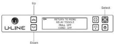
text_image
U-LINE Up RETURN TO MENU BEAV TONGLE HULL OFF COND. OFF Select DownRelay toggle is used to manually switch the state of each relay to test for proper operation. In addition to the AC relays, DC switches may also be toggled. Relay toggle can also be used to force the unit into a particular state.
| ID | Description | Voltage |
| Mull | Mullion Heater (Not Used) | AC |
| Cond | Fan (Not Used) | AC |
| Def | Defrost Valve (45cm models) | AC |
| Pan | Pan heater (Not Used) | AC |
| Comp | Compressor | AC |
| F1 | Evaporator Fan | DC |
| F3 | Condenser Fan | DC |
| L1 | Zone Lighting | DC |
To access Relay Toggle
-
Press ☑ to select "Relay Toggle".
-
Press
Input Status

text_image
Up U-LINE Down RETURN TO MENU INPUT STATUS DOOR OPEN JIN2.OPEN SelectInput status displays the current state of each available input.
| ID | Description | State |
| Door | Door Switch | Open - Closed |
To access Input Status
-
Press ☑ to select "Input Status".
-
Press
-
Press 🔒 and ☑ to scroll through available information.
To exit the Input Status menu press 📋 to select "Return to Menu" and press 🔒 to confirm outputs.
SAFETY • INSTALLATION & INTEGRATION • OPERATING INSTRUCTIONS • MAINTENANCE • SERVICE
To access Outputs
-
Press ☑ to select "Outputs".
-
Press
-
Press 🔒 and 🔒 to scroll through available information.
To exit the Input Status menu, press 🔒 to select "Return to Menu" and press 🔒 to confirm.
Offsets
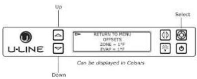
text_image
U-LINE Up Select RETURN TO MENU OFFSETS ZONE = 1°F FVAP = 1°F Down Can be displayed in CelsiusNOTICE
Customer care MUST be notified and approve of any changes to the differential before they are made. Failure to notify customer care will void the warranty.
- Press ☑ and ☑ to scroll through available thermistors.
To change offsets
-
Press ☐, the selected thermistor will begin to flash.
-
Press ☐ or ☑ to modify offset value.
-
Press 🔒 to confirm setting.
To exit the Offset menu, press 🔒 to select "Return to Menu" and press 🔒 to confirm.
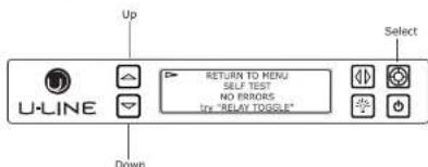
Self Test
text_image
Up U-LINE RETURN TO MENU SELF TEST NO ERRORS TRY "RELAY TOGGLE" Select DownSelf test is used to initiate a self diagnostic report. Any system faults will be displayed under Self test. If no errors are present "no errors" will be displayed and the main control board is functioning properly. The main control
SAFETY • INSTALLATION & INTEGRATION • OPERATING INSTRUCTIONS • MAINTENANCE • SERVICE
Differentials

text_image
Up U-LINE RETURN TO MENU DIFFERENTIALS ZONE = 1°F. Select Down Can be displayed in Celsius(DO NOT MAKE AN ADJUSTMENT TO THIS WITHOUT CONTACTING TECH LINE: 800-779-2955)
Differentials are used to determine the maximum variation from set point and have a range of 0 through 10. The table below shows the effect of differentials on cooling cycles with a set point of 45^ (7^) .
NOTE: Air temperature does not reflect product temperatures.
| Differential | Cycle Start °F (°C) | Cycle End °F (°C) |
| 0 | 45^ ( 7^ ) | 43^ ( 6^ ) |
| 1 | 46^ ( 8^ ) | 43^ ( 6^ ) |
| 2 | 47^ ( 8^ ) | 41^ ( 5^ ) |
| 3 | 48^ ( 9^ ) | 41^ ( 5^ ) |
| 4 | 49^ ( 10^ ) | 39^ ( 4^ ) |
| 5 | 50^ ( 10^ ) | 37^ ( 3^ ) |
The graph below shows a unit's cooling cycle over time with various differentials.
Evap Fan

text_image
Up U-LINE RETURN TO MENU EVAP FAN EVAP FAN ON = 1 EVAP FAN OFF = 60 Down SelectThe Evap Fan option in the service menu allows servicers to change the Evaporator Fan runtime (in minutes) from 0 to 98 and OFF cycle time 0 to 98.
To access Evap Fan
-
Press ☑ to select "Evap Fan".
-
Press
-
Press ☐ and ☑ to scroll through available settings.
To exit the Evap Fan menu, press 🔒 to select "Return to Menu" and press 🔒 to confirm.
Mullion
SAFETY • INSTALLATION & INTEGRATION • OPERATING INSTRUCTIONS • MAINTENANCE • SERVICE
Factory Default

text_image
U-LINE Up RETURN TO MENU FACTORY DEFAULT RESTORE? Select DownFactory Default will restore all settings to their factory default.
Re-Select Model allows the units model information to be modified. Changing the units model completely reprograms available zones, relay assignments, DC output assignments etc.
To access Re-Select Model
-
Press ☑ to select "Re-Select Model".
-
Press
To change model setting
-
Press ☑ to select "Model=" and press 🔒. "Model" will begin to flash.
-
Press ☐ or ☑ to scroll through each available model.
-
Press Ⓗ to confirm. While processing, the ▶ will momentarily change to *.
To exit Re-Select Model, press 🔒 to select "Return to Menu" and press 🔒 to confirm. (Power cycling unit is recommended after re-selecting model.)
Factory Wi-Fi
Up
Select
SAFETY • INSTALLATION & INTEGRATION • OPERATING INSTRUCTIONS • MAINTENANCE • SERVICE
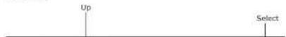
Set Points
text_image
Up U-LINE RETURN TO MENU SET POINTS ZONE = 35°C EVEF = 55°C Select DownThe Set points menu contains options to modify both the Zone and Evap set points. Changes to the zone set point will be reflected on the main screen. Changes to the evap set point alter the temperature the evaporator needs to meet during a defrost cycle.
To access Set Points
-
Press ☑ to select "Set Points".
-
Press
-
Press ☑ and ☑ to scroll through available set points.
To change set points
-
Press ☐, the selected set point will begin to flash.
-
Press 🔒 or 🔒 to modify the value.
The Fan Delay menu option allows the modification of fan run times during and after a cooling cycle. In order to allow time for the evaporator to properly cool, the evaporator fan is delayed from starting with the cooling cycle for a given amount of time. In order to remove as much warmth as possible from the cabinet the evaporator fan will continue to run at the end of the cooling cycle for a given amount of time.
Fan Delay On=
"Fan Delay On" is the amount of time in minutes the fan will be delayed from starting from the beginning of a cooling cycle.
Fan Delay Off=
"Fan Delay Off" is the amount of time in minutes the fan will continue to run at the end of a cooling cycle.
To access Fan Delay
-
Press ☑ to select "Fan Delay".
-
Press
To change fan delay
-
Press ☑ to select either "Fan Delay On" or "Fan Delay Off" and press Ⓗ. The chosen option will begin to flash.
-
Press ☐ or ☑ to change settings.
SAFETY • INSTALLATION & INTEGRATION • OPERATING INSTRUCTIONS • MAINTENANCE • SERVICE
To toggle showroom mode
- Press ☑ to select "Showroom Mode".
- Press
- Press ☑ to select "Off" and press 🔒, "Off" will begin to flash.
- Press ☐ or ☑ to toggle between off and on.
- Press 📋 to confirm.
If set to "on" showroom mode will begin immediately. To exit showroom mode press ⏻ and hold for 5 seconds and release. The display will show a countdown to switching the unit off. Press ⏻ again and the unit will immediately switch on retaining the presets from before it entered showroom mode.
To exit the showroom mode menu, press 🔒 to select "Return to Menu" and press 🔒 to confirm.
SAFETY • INSTALLATION & INTEGRATION • OPERATING INSTRUCTIONS • MAINTENANCE • SERVICE
Thermistors
Thermistors are used for various temperature readings. Thermistors provide reliable temperature readings using a resistance which varies based on surrounding temperatures. If a faulty thermistor is suspected it may be tested using an accurate ohmmeter.
All thermistors in the unit are identical. If a thermistor is suspected of being defective the resistance can be verified. Place the thermistor in an ice water bath, the resistance should read 16.1k OHMs +/-5% on your meter.
Thermistor connections must be kept clean. A thermistor connection that has become corroded can cause resistance values from the thermistor to change as they pass through a dirty connection to the board.
It is for that reason that we apply dielectric grease to all of our thermistor connections. Dielectric grease will help to keep thermistor connections clean and dry.
If you change a thermistor in the unit please re-apply dielectric grease to the connection. If you encounter a dirty thermistor connection, you should replace the thermistor and the thermistor harness.
Thermistor error information can be found in the Control
Thermistor three (Ambient):
Located in the base of the unit (secured to the condenser). It is used to monitor the ambient temperature within the base compartment. It is used for diagnostics.
THERMISTOR FAILURE
Zone Thermistors
If a zone thermistor(s) in the unit fails the unit will continue to cool in a backup mode (Self Preservation Mode) to preserve the integrity of the contents. The unit will otherwise operate normally.
2000 Series Self Preservation Mode:
The unit will cycle on for 10 minutes then off for 40 minutes.
3000 Series Self Preservation Mode:
Cycle times determined by zone - see chart. The error will be displayed on the main display, "Self Test" and logged in "All Errors."
Self Preservation Mode Data Table - 3000 Series
| Mode | ON | OFF |
| Beverage/Drinks | 10 | 45 |
| Market/Fresh | 10 | 45 |
| Root | 5 | 90 |
| Poultry | 10 | 45 |
SAFETY • INSTALLATION & INTEGRATION • OPERATING INSTRUCTIONS • MAINTENANCE • SERVICE
Thermistor Resistance Data
| Temp (F) | Temp (C) | Nominal Resistance (OHMS)* |
| -40 | -40 | 169157 |
| -31 | -35 | 121795 |
| -22 | -30 | 88766 |
| -13 | -25 | 65333 |
| -4 | -20 | 48614 |
| 5 | -15 | 36503 |
| 14 | -10 | 27681 |
| 23 | -5 | 21166 |
| 32 | 0 | 16330 |
| 41 | 5 | 12696 |
| 50 | 10 | 9951 |
| 59 | 15 | 7855 |
| 68 | 20 | 6246 |
| 77 | 25 | 5000 |
| 86 | 30 | 4029 |
| 95 | 35 | 3266 |
| 104 | 40 | 2665 |
| 113 | 45 | 2186 |
| 122 | 50 | 1803 |
| 131 | 55 | 1495 |
| 140 | 60 | 1247 |
| 149 | 65 | 1044 |
| 158 | 70 | 879 |
| 167 | 75 | 743 |
| 176 | 80 | 631 |
SAFETY • INSTALLATION & INTEGRATION • OPERATING INSTRUCTIONS • MAINTENANCE • SERVICE
Defrost
The models below have automatic or frost free design and do not require manual defrosting under normal conditions.
| Defrost Settings | ||||
| Base Model | Variant(s) | Compressor Run Time Between Defrost (Hours) | Duration in Minutes (Maximum) | Stop Temperature °F (°C) |
| 1224 | RF | 12 | 45 | 15 (-9) |
| 1215/1224/2218/2245/2224/2260 | WC, ZWC | 12 | 45 | 45 (7) |
| 1215/1224/2218/2245/2224/2260 | R, RSOD, RDC, BEV, DC, DWR, RGL | 12 | 45 | 42 (6) |
| CO29 | F | 12 | 18 | n/a |
| CO1224 | F | 12 | 18 | 45 (7) |
| 1224FZR | Freezer Mode | 6 | 45 | 42(6) |
| 1224FZR | Refrigerator Mode | 12 | 45 | 42(6) |
The defrost settings for 3000 series models are determined by zone.
| Defrost Settings by Zone (3000 Series) | ||||
| Zones | Compressor Run Time Between Defrost (Hours) | Duration in Minutes (Minimum) | Duration in Minutes (Maximum) | Stop Temperature °F (°C) |
| Beverage/Drinks | 12 | 5 | 60 | 42 (6) |
| Market/Fresh | 12 | 5 | 60 | 42 (6) |
| Root/Root Cellar | 12 | 5 | 60 | 45 (7) |
| Pantry | 12 | 5 | 60 | 42 (6) |
| White Wine | 12 | 5 | 60 | 45 (7) |
| Red Wine | 12 | 5 | 60 | 45 (7) |
| Sparkling Wine | 12 | 5 | 60 | 45 (7) |
| Polar | 6 | 5 | 20 | 42 (6) |
SAFETY • INSTALLATION & INTEGRATION • OPERATING INSTRUCTIONS • MAINTENANCE • SERVICE
Remove Fan and Cover
CONVECTION COOLING
This unit is equipped with an advanced convection cooling system. Convection cooling stabilizes cabinet temperature, cools product faster and increases energy efficiency.
Evaporator Fan
The evaporator fan is responsible for circulating warm air from the refrigeration zone, past the evaporator and back into the refrigerated zone.
The evaporator fan is factory set to have a 1 minute delay at the beginning of a cooling cycle. This delay gives the evaporator time to cool properly before warm air is passed over it. The fan will continue to run for an additional 2 minutes at the end of a cooling cycle. Fan delay times can be modified through the service menu.
Evaporator fan operation is also determined by door switch state. If the door switch circuit opens, the fan will stop. When the door switch circuit is closed the fan will either continue running with the cooling cycle, or if not currently cooling, the fan will run for 1 minute to circulate air and clear any condensation that may have appeared on glass doors and shelves.
-
Disconnect power to the unit,
-
Remove rear cover from unit.
-
Disconnect fan electrical connection at rear of unit.
-
Remove insulating foam from refrigerant line pass-through hole as needed to gain clearance for fan plug.
-
Remove internal shelving.
B. Remove rear shelf clips, fronts can remain.
-
Remove thermistor cover.
-
Remove two evaporator cover screws from top of evaporator plate.

SAFETY • INSTALLATION & INTEGRATION • OPERATING INSTRUCTIONS • MAINTENANCE • SERVICE
- Remove the 4 screws mounting the fan shroud to the evaporator plate.

text_image
Air Flow- Remove and replace fan. Take special care to properly route fan wire.
NOTICE
Fan must be oriented to pull air in through lower evaporator cover vents and push air out at fan mounting location.
15. Installation is the reverse of removal.
16. Care must be taken to assure the bottom of the evaporator cover is reinstalled behind the front edge of the train trough.