
Flex Plex 29525 - Projection Cabinet DA-LITE - Free user manual and instructions
Find the device manual for free Flex Plex 29525 DA-LITE in PDF.

| Product Type | In-Wall Rear Projection Screen (Polacoat) |
| Model | Flex Plex 29525 |
| Brand | Da-Lite |
| Screen Surface Material | Polacoat® rear projection screen surface |
| Frame Material | Aluminum |
| Installation Type | In-wall, requires wall opening |
| Minimum Number of Installers | 4 people |
| Required Tools (not included) | Screw gun/drill, drill bits, knife, 1/2" open wrenches, ladders, measuring tape, level, rubber mallet, 1/8" & 3/16" hex keys, 1/4" × 1" hex lag screws, #10 × 1" countersunk flat head screws |
| Acclimation Time Before Installation | 48 hours (rolled), plus 4 hours (unrolled flat) |
| Included Accessories | Screen surface, T-tracks (6), trim pieces (2), lifting brackets (3), gloves (4 pairs), rubber gaskets (4), frame pieces (6), hoisting brackets (2), cap screws (4), seam bracket (4), corner bracket (4), 3/8×1/2 hex head screws (24) |
| Cleaning – Screen Surface | Gentle blotting with clean lint-free cloth; for dry soil marks, use VM&P Naptha or Da-Lite Lenskleen |
| Cleaning – Frame | Dilute detergent and water with soft cloth; avoid abrasives and solvents |
| Screen Orientation | Polished surface faces projector, matte surface faces audience |
| Anti-Glare Coating | If present, anti-glare surface must face projector |
| Warranty | 5 years limited (to original purchaser) |
| Dimensions (Screen Size) | Custom – wall opening must be 5" larger than viewing height and width each |
| Weight | Varies by size (not specified) |
| Usage | Indoor rear projection only |
| Safety Warning | Do not step on or place objects on screen surface; avoid twisting/bowing during lifting |
Frequently Asked Questions - Flex Plex 29525 DA-LITE
User questions about Flex Plex 29525 DA-LITE
0 question about this device. Answer the ones you know or ask your own.
Ask a new question about this device
Download the instructions for your Projection Cabinet in PDF format for free! Find your manual Flex Plex 29525 - DA-LITE and take your electronic device back in hand. On this page are published all the documents necessary for the use of your device. Flex Plex 29525 by DA-LITE.
USER MANUAL Flex Plex 29525 DA-LITE
natural_image
Empty white rectangular frame with black border (no text or symbols)Disclaimer
Milestone and its affiliated corporations and subsidiaries (collectively "Milestone"), intend to make this manual accurate and complete. However, Milestone makes no claim that the information contained herein covers all details, conditions or variations, nor does it provide for every possible contingency in connection with the installation or use of this subject to change without notice or obligation of any kind. Milestone makes no representation of warranty, expressed or implied, regarding the information contained herein. Milestone assumes no responsibility for accuracy, completeness or sufficiency of the information contained in this document.
Da-Lite ^® is a registered trademark of Milestone AV Technologies. All rights reserved.
Maintenance and Protection
Projection screens should always be installed after the completion of construction, crywall, and painting of all adjacent areas. If construction work needs to occur near an installed screen, clean polyethylene sheeting should be used to cover and protect both surfaces. Never apply adhesive tapes to the coated surface. Always be careful to guard the screen against damage from moving scaffolding, ladders, or staging materials.
General Cleaning
Never use solvents on or near Da-Lite rear projection screens. Remove dust by gently blotting the screen with a soil, clean, lint-free cloth.
Dry Soil Marks
Clean with VM&P Naptha or with Da-Lite Lenskleen and a soft, clean, lint-free cloth.
Cleaning of Frame and Trim
The exposed surfaces of the aluminum frames can be cleaned with a dilute solution of detergent and water, followed by a clear water rinse. Use a soft, grit-free cloth to preserve the anodized finish. Protect screen surface during frame cleaning. Do not use abrasive cleaners or solvents.
Preparation
It requires at least four people to assemble a Flex Plex screen. To maintain optimal image geometry and screen alignment, a flat and straight wall free from obstructions and angular distortions should be used. A wall opening with 5" + the ordered viewing height and 5" + the ordered viewing width must be used to maintain the precise in-wall fit of the Flex Plex screen. When assembling the screen, choose a clean work area using packed material or other soft clean materials. The work area should be larger than the overall screen size and directly in front of the wall opening where the screen is to be installed (audience side).
NOTE: Please read through the installation steps and note wait times. The rolled screen surface needs to be accimated to the room for 48 hours prior to installation (Step 1). Once the surface is unrolled it will need to lay in its unrolled state for 4 hours (Step 2).
Tools Required for Installation (not provided)
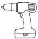
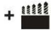
Screw Gun/Drill and Drill Bits

Knile

1/2" Open Wrenches

(2) Ladders


Measuring Tape LevelRubber Mallet
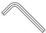
1/8" & 3/16" Hex Keys

1/4" × 1" Hex Lag Screws
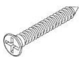
10 x 1 Countersunk
Flat Head Screws
Included Parts and Hardware
NOTE: Quantities listed are for standard sizes. Quantities will vary if a custom screen that is larger than standard is ordered.

A(1)
Screen Surface
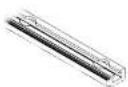
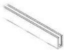
B(6)
T-Tracks
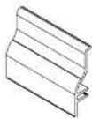
C(2)
4" Pieces of Trim
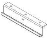
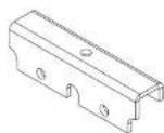
D(3)
Lifting Brackets

E (4) pairs
Gloves
F(4)
Rubber Gaskets

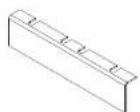
G(6)
Frame Pieces
H(2)
Hoisting Brackets

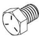
1(4)
Cap Screws
J(4)
Seam Bracket

K(4)
Corner Bracket
L(24)
3/8 x 1/2 Hex Head Screws
Screen Orientation
Polacoat® In Wall rear projection screens have a polished surface and a matte, coated surface. The polished surface should always be installed so that it faces the projector and the matte surface must face the audience. If screen has anti glare coating, the anti glare surface should always face the projector.
Installation
- Prepare clean working area and use padded materials or soil, clean materials in the space where the screen will be assembled on the floor.
WARNING: The screen surface should be allowed to acclimate to the temperature and humidity of the location where it will be installed. Da-Lite does not recommend beginning installation if there is high humidity in the room. Care should be taken to prevent water from condensing on the screen surface as it may leave permanent marks on the screen surface.
NOTE: Da-Lite recommends that the roll with screen surface and hardware be removed from the crate and acclimated to the location at least 48 hours prior to installation.
NOTE: Wear the provided gloves (E) any time the screen surface is being handled and also curing lifting to provide grip. -
Carefully unpack unit, from crate and packaging. Remove carton from crate before unpacking. Remove too of carton to unpack the screen surface and hardware.
NOTE: If possible, move crate into the room where screen will -
Using four people, unroll the screen (A). Locate one person on each end of the roll with the other two people used as support for the middle of the roll. Before unrolling the screen, ensure that the edge/end of the surface is nearest to the floor. While maintaining slight pressure on the roll, cut each piece of tape wrapped around the roll at the edge/end of the surface. Once all tape pieces have been cut, the screen surface can be unrolled. This should be done gently and in at a measured pace to prevent damage to the surface. There will be elastic potential energy stored in the roll. Carefully guide the screen surface when unrolling, particularly on the last wrap to prevent the surface from springing out or scraping itself. The audience side of the screen surface will be face down after it has been unrolled.
WARNING: Do not step on the screen surface or place objects on the screen surface during this step or during installation. This may cause irreparable damage to the projection coating.
NOTE: Da-Lite recommends that the screen surface remain in this flat, unrolled state for at least 4 hours prior to Step 10. This will allow the screen surface to fully adjust to room
Installation (continued)
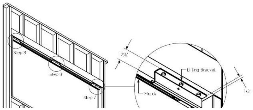
- While the screen is resting, the T tracks (B) can be installed into the wall opening. Measure 2½ from the side of your wall opening to locate the end of the first T track (B) piece (See Figure 1). Using one of the 4" pieces of trim (C), snap the trim into place on one end of the T track (B), place the T track in the opening and slice until the lower portion of the trim is against the wall. Secure that end of the track with a #10 screw in the hole closest to the end (See Figure 2).
NOTE: Most screen units will have one piece of T-track (B) for the side openings and two pieces each for the top and bottom wall openings. Larger sized units (above 14' wide) may have three pieces of T-track (B) each for the top and bottom openings
WARNING: Ensure each #10 countersunk screw head is inserted completely and does not extend into the T-track channel. If the screws are not inserted completely, the screen tensioning assemblies will not slide through the channel.

natural_image
Pure architectural line drawings of two structural components without any text or symbolsInstallation (continued)
- Using the other 4" piece of trim (C) as a guide, secure the opposite end of the T-track (B) section on the end hole with a #10 screw. Once both ends are attached, slide the 4" trim (C) pieces along the track to align the other positions and attach a #10 screw into the hole openings until completed (See Figure 2)
NOTE: Sliding the trim along the T-track (B) will maintain the proper alignment when attaching the T-track (B) to the wall. This alignment is necessary to allow the trim to snap on easily at the end of the screen installation. Ensure the opening is level on all four sides. If the opening is not level, the T-track (B) will need to be shimmed in order to ensure the screen trim is level once attached to the T-track (B).
- Repeat Steps 4 and 5 until all T-track (8) sections have been secured to the wall opening (See Figure 3). For top and bottom sections, use 4" piece of trim (C) to overlap at the seams as a guide to ensure that both T-track (8) pieces are flush with each other in the wall opening.

Installation (continued)
- Mount the first lifting bracket (D) in the top section of the wall opening behind the T-track (B). Measure 2% from the back (protractor side) of the T-track (B) to the back edge of the lifting bracket (D) and 1/2' from the edge of the opening to position the bracket, correctly. Use 1/4" x T-tag screws to attach the bracket (See Figure 4).
NOTE: Lifting brackets (D) must be parallel to T-track. When installed in the correct orientation, the bottom lip of the lifting bracket (D) will be the side closest to the T-track (B).
-
Repeat for the second lifting bracket (D) at the top section of the screen in the opposite corner (See Figure 4).
-
Position the third lifting bracket (D) 2½" from the back of the T-track (B) in the center of the top section of the wall opening and mount with 1/4" X T lag screws (See Figure 4).
NOTE: After completing this step, there should be three lifting brackets (D) mounted into the top section of the wall opening behind the T-track (B). Check that these brackets are secure. They will be used to guide the screen surface into place and support its weight until the T-track (B) and screen frame are attached to each other.
WARNING: After completing this step, do not proceed further in the instructions until the screen surface has remained in a flat, unrolled state for at least 4 hours.
Installation (continued)
- At the unrolled screen surface (A), peel back the protective paper approximately 3/4" on the top and the bottom. This will allow the frame to be attached easily to the screen surface.
NOTE: Do not remove the protective paper completely. This will be done at the end of the screen installation in order to protect the surface during the hanging process.
Da-Lite recommends that the provided gloves (E) be worn at this time in order to prevent damage to the screen surface and to provide grip while lifting.
-
Center the first rubber gasket (F) on the screen surface edge and press it into place starting at one end. Repeat this step for the three remaining sides of the screen.
-
Place the frame sections (G) around the screen surface (A). Attach to frame (G) over the rubber gasket (F) with set screws facing upwards. Use a rubber mallet to gently tap the screen frame into place if needed (See Figure 5)
-
Place the hoisting bracket (H) in the center of the top and bottom sections of the screen frame. Attach to frame using the provided cap screws (I) and a 3/16" hex key.
-
Starting from the center on each side, tighten all set screws on all four sides of the frame using the 1/8" hex key. Approximately two threads should be visible on each set screw when properly tightened.
-
Prepare to attach the seam brackets (J) and corner brackets (K) by carefully sliding the 3/8" x 1/2" hex head screws (L) down the frame channel (two bolts on either side of the seam and two on each side of each corner).
-
Carefully slide the seam bracket (J) under the assembled frame, aligning the bracket and 3/8" screws (L) across the seam. Secure using the 3/8" thin hex nuts (M) and lighten completely.
-
Repeat for corner brackets (K).

flowchart
graph TD
    A["Corner Brackets"] --> B["Pre-Attached Hoisting Brackets"]
    B --> C["Seam Bracket"]
    C --> D["Hoisting Bracket"]
    D --> E["Rubber Gasket"]
    F["Frame Section"] --> C
    F --> D

Installation (continued)
- Feed the first rope (N) through the large hole on the audience left moistling bracket (H) so that the knotted end makes contact with the inside of the bracket. Then, feed the rope (N) through the audience left lifting bracket (D). that was installed into the wall opening behind the T track (B) (See Figure 6).
- Repeat for the second rope (N) through the center and the third rope (N) through the audience right hoisting (HD) and lifting brackets (D) (See Figure 6).
NOTE: At this point, all three ropes (N) should be fed through the hoisting (H) and lifting brackets (D). There will be no rope (N) placed through the single hoisting bracket (H) on the bottom of the screen. On the rear (projector side) of the wall opening, a person will be needed in the following steps to guide the three ropes (N) as the screen is being lifted.
- Lill the screen assembly to a vertical position on the floor parallel to the wall opening. On the projector side of the wall opening, one person will be holding all three ropes (N) without slack and guiding the screen to an upright position. On the audience side of the wall opening, to lift, there should be one person on the left side of the screen, one person on the right and one person supporting the top center of the screen frame at the center hoisting bracket (H). After this step is completed, the screen will be standing on the floor in front of the wall opening (See Figure 7).
▲AUTION: Do not allow the screen to twist or bow during this step. Without careful lifting, there is potential to crack, break or shatter the screen surface. Four people must be used during this step.
WARNING: Screen must be positioned close to, but not touching, the wall before lifting. Do not lift the screen into place if the ropes have not been fed through the hoisting (H) and lifting brackets (D).
Installation (continued)
-
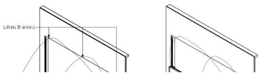
Raise the screen assembly into the wall opening. On the projector side, one person will remain holding all three ropes (N) without slack guiding the screen into place. On the audience side, two people will lift the screen vertically; one on the left and one on the right side. These three people (one rope control and two lifters) will coordinate together to lift the screen into place. The fourth person should be on a ladder on the projector side holding the rope control and lifters guide the screen assembly into place until all three hoisting and lifting brackets attach to each other at the top of the wall opening (See Figure 8).
-
Once the screen is hanging on the hoisting and lifting brackets, carefully remove the seam (J) and corner (K) brackets along with the 3/8' screws (L) and nurs (M).
NOTE: During this step, be careful not to touch the projection coating on the audience facing side of the screen assembly along the screen edges.
NOTE: At the end of this step, the screen assembly's weight should be supported by the hoisting and lifting brackets and it should be centered side to side inside of the wall opening.
Gloves can be removed at this time.
natural_image
Simple line drawing of a rectangular frame with vertical supports (no text or symbols)
Installation (continued)
- At the top section, align the T-track and the frame. Insert eight tensioning assemblies (O) (four per frame section for larger screens). Align the tensioning assemblies (O) so that they are evenly spaced across the length of T-track and frame. See Figure 9.
- Tighten a minimum of two tensioning assemblies (0) per frame section between the T-track and frame using a 1/2" wrench. After two or three turns on one tensioning assembly, move to another in order to prevent the bolts and nuts from binding. Keep using this alternating method until at least two (or more) tensioning assemblies, per frame section, have secured the frame to the T-track on the top section of the screen assembly. As the tensioning assemblies are tightened the screen frame will pull gradually closer to the T-track. Do not tighten fully at this time.
AUTION: Do not proceed to next steps until a minimum of two tensioning assemblies (O) per frame section are attached fully and are holding the screen weight on the top side.
- Remove the three lifting brackets (D) from the wall opening behind the T-track by loosening and removing the 1/4" x 1" lag screws. The three ropes (N) should also be removed at this time.
NOTE: Once the lifting brackets have been removed, the screen assembly will be held in place by the previously attached tensioning assemblies.
- Tighten all tensioning assemblies (O) on the top section of the screen assembly until all eight (four per frame section) are evenly spaced and secure on the top side.
NOTE: Use the alternating method of two to three turns on one assembly then moving to another assembly to prevent the bolts and nuts from binding. - At the bottom section, align the T-track and the frame. Insert eight tensioning assemblies (O) (our per frame section for larger screens). Align the tensioning assemblies (O) so that they are evenly spaced across the length of T-track and frame.
- Begin tightening the tensioning (O) assemblies between the T-track and frame using a 1/2" wrench. After two or three turns on one tensioning assembly, move to another in order to prevent the bolts and nuts from binding. Keep using this alternating method until the tensioning assemblies have secured the frame to the T-track.
NOTE: These tensioning assemblies (O) do not need to be tightened down completely (no threads showing) because the top frame is already anchoring the screen in place. The bottom needs to be secure enough to the installer's discretion. - Repeat Steps 27 and 28 for the left and right sides of the frame, using four tensioning assemblies (O) per frame section.
Installation (continued)
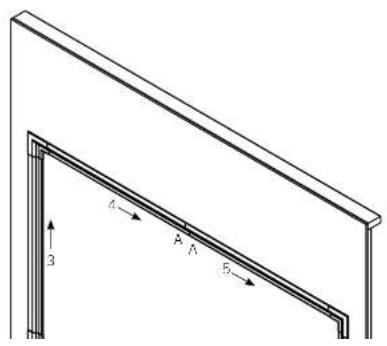
- Assemble the six provided trim pieces (P). The two top pieces will be labeled "A" at the 45 degree overlap and the two bottom pieces will be labeled "B". The remaining two pieces are for the sides and are interchangeable.
- Starting at the audience side bottom right corner, align the first piece of bottom trim (P) with the bottom edge of the screen. The end should be approximately 3" from the corner of the wall opening. When aligned, snap the trim (P) onto the T track while moving along the length of the piece until firmly in place. Align the second bottom piece of trim (P) at the 45 degree overlap and snap onto the T track starting at the overlap while moving along the length of the piece until firmly in place (Figure 10).
NOTE: Custom screens may use three pieces.
- Starting at the audience side bottom left corner, align a side piece of trim (P) with the side edge of the screen. The end should be approximately 3' up from the corner of the wall opening. When aligned, snap the trim (P) onto the T-track while moving along the length of the piece until firmly in place (Figure 10).
- Repeat Step 31 for the top trim pieces (P) and Step 32 for the audience right trim piece (P) (Figure 10).
- Place corner covers (Q) over each corner to check it and alignment. Adjust trim if necessary. When satisfied with desired placement of all four corner covers (Q), peel the red release liners from the two pieces of adhesive and firmly press each corner cover into place (Figure 10).
- Carefully remove the protective paper on the projector side of the screen surface to complete the installation.

Warranty
LIMITED FIVE YEAR WARRANTY ON DA-LITE POLACOAT IN-WALL REAR PROJECTION SCREENS
Milestone AV Technologies LLC warrants this DaLite branded product to the original purchaser only, to be free from defects in materials and workmanship for a period of five (5) years from the date of purchase by the original purchaser; provided they are properly operated according to DaLite's instructions and are not damaged due to improper handling or treatment after shipment from the factory.
This warranty does not apply to equipment showing evidence of misuse, abuse or accidental damage, or which has been tampered with or repaired by a person other than authorized Da-Lite personnel.
Da Lile's sole obligation under this warranty shall be to repair or to replace (a) Da Lile's option) the defective part of the merchandise. Returns for service should be made to your Da Lile dealer. If it is necessary for the dealer to return the screen or part to Da Lile, transportation expenses to and from
Da-Lite are payable by the purchaser and Da-Lite is not responsible for damage in shipment.
To protect yourself against damage or loss in transit, insure the product and prepay all transportation expenses.
TO THE MAXIMUM EXTENT PERMITTED BY APPLICABLE LAW, THIS WARRANTY IS IN LIEU OF ALL OTHER WARRANTIES, EXPRESS OR IMPLIED, INCLUDING WARRANTIES AS TO FITNESS FOR USE AND MERCHANTABILITY. Any implied warranties of fitness for use, or merchantability, that may be mandated by statute or rule of law are limited to the five (5) year warranty period. This warranty gives you specific legal rights, and you may also have other rights, which vary from state-to-state.
TO THE MAXIMUM EXTENT PERMITTED BY APPLICABLE LAW, NO LIABILITY IS ASSUMED FOR EXPENSES OR DAMAGES RESULTING FROM INTERRUPTION IN OPERATION OF EQUIPMENT, OR FOR INCIDENTAL, DIRECT, OR CONSEQUENTIAL DAMAGES OF ANY NATURE.
In the event that there is a defect in materials or workmanship of a De Lile product, you may contact our Customer Care Specialists at 3100 North Detroit Street, Warsaw, IN 46582 (574) 267-8101 (800) 622-3737
IMPORTANT: THIS WARRANTY SHALL NOT BE VALID AND DA-LITE BRANDED PRODUCTS SHALL NOT BE BOUND BY THIS WARRANTY IF THE PRODUCT IS NOT OPERATED IN ACCORDANCE WITH THE DA-LITE WRITTEN INSTRUCTIONS.
Keep your sales receipt to prove the date of purchase and your original ownership.


- Disclaimer
- Maintenance and Protection
- General Cleaning
- Dry Soil Marks
- Cleaning of Frame and Trim
- Preparation
- Tools Required for Installation (not provided)
- x 1 Countersunk
- Included Parts and Hardware
- Screen Orientation
- Installation
- Installation (continued)
- Da-Lite recommends that the provided gloves (E) be worn at this time in order to prevent damage to the screen surface and to provide grip while lifting.
- AUTION: Do not proceed to next steps until a minimum of two tensioning assemblies (O) per frame section are attached fully and are holding the screen weight on the top side.
- Warranty
- LIMITED FIVE YEAR WARRANTY ON DA-LITE POLACOAT IN-WALL REAR PROJECTION SCREENS
Brand : DA-LITE
Model : Flex Plex 29525
Category : Projection Cabinet