ViewShare Advantage Retrofit 25055 - Armoire de projection DA-LITE - Free user manual and instructions
Find the device manual for free ViewShare Advantage Retrofit 25055 DA-LITE in PDF.

User questions about ViewShare Advantage Retrofit 25055 DA-LITE
0 question about this device. Answer the ones you know or ask your own.
Ask a new question about this device
Download the instructions for your Armoire de projection in PDF format for free! Find your manual ViewShare Advantage Retrofit 25055 - DA-LITE and take your electronic device back in hand. On this page are published all the documents necessary for the use of your device. ViewShare Advantage Retrofit 25055 by DA-LITE.
USER MANUAL ViewShare Advantage Retrofit 25055 DA-LITE
natural_image
Pure white rectangular object with no visible text, numbers, or symbols
natural_image
Black rectangular frame with a roller on top, no text or symbols visibleINSTRUCTION BOOK FOR
ViewShare Advantage Electrol Retrofit
Important Safety Instructions
When using your video equipment, basic safety precautions should always be followed, including the following:
- Read and understand all instructions before using.
- Position the cord so that it will not be tripped over, pulled, or contact hot surfaces.
- If an extension cord is necessary, a cord with a current rating at least equal to that of the appliance should be used. Cords rated for less amperage than the appliance may overheat.
- To reduce the risk of electric shock, do not disassemble this appliance. Contact an authorized service dealer when repair work is required. Incorrect reassembly can cause electric shock when the appliance is used subsequently.
- The use of an accessory attachment not recommended by the manufacturer may cause a risk of fire, electric shock, or injury to persons.
Save These Instructions
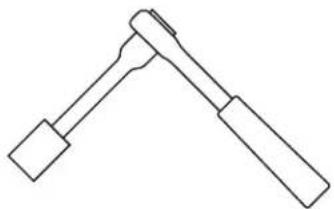
Tools Required for Installation
natural_image
Simple line drawing of a symmetrical mechanical or electrical component with two ends (no text or symbols)7/16" Socket Driver with 6" Extension

natural_image
Simple line drawing of a bent pipe or rod (no text or symbols)18 " Hex Key (included)
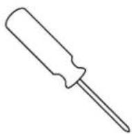
2 Phillips Screwdriver
Pre-Installation
Prior to Retrofit installation, you will need to run a CAT5 or CAT5e network cable from the motor end of your screen to the area in which your computer will be located. THE CAT5 CABLE IS NOT PROVIDED. The length of the CAT5 cable cannot exceed 200 feet. See Pre-Installation of ViewShare Screen and Roller Assembly and Camera and Speakerphone Installation sections for additional details on CAT5 cable connections.
NOTE: It requires at least two people to install a ViewShare Retrofit.
- Run the screen to the up position.
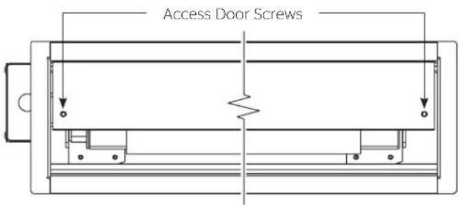
- Remove the access door by removing the screws from each end (Figure 1). Be sure to support the door during this step to avoid injury. Lift the door slightly and pull away from the edge of the case.
- Unplug 3 or 4 wire motor connector and RJ-22/45 cable (if applicable) from the junction box. See Appendix A for motor type details.
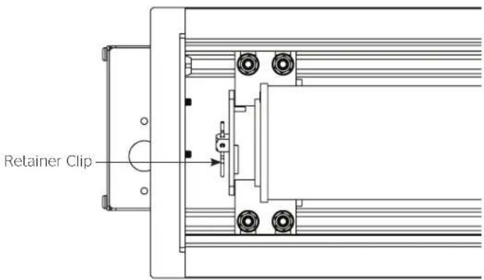
- Remove retainer clip from the motor (Figure 2).
NOTE: Save retainer clip for use in the installation of the ViewShare screen and roller assembly.
- Loosen (but do not remove) four 14 - 20 nuts securing pin end bracket (opposite end from the junction box) to the case housing. While supporting the screen and roller, slide the pin end bracket towards the end of the case and remove the existing screen and roller assembly (Figure 3).
NOTE: Some units may only have two nuts per bracket.

text_image
Access Door ScrewsFigure 1
text_image
Retainer ClipFigure 2 - Motor End

text_image
¼ -20 Nuts Pin End Bracket ¼ -20 NutsFigure 3
- Remove existing motor and pin end roller assembly brackets from inside the case.
NOTE: At this point the inside of case will be empty except for the junction box connections on the motor end.
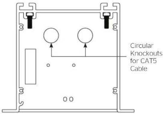
- Remove a single circular knockout from motor end of case for CAT5 cable needed in the Installation of ViewShare Screen and Roller Assembly (Figure 4).
NOTE: The CAT5 cable should be run from the Local CAT5 to USB Extender in Camera and Speakerphone Installation to this location. Final connection of this CAT5 cable running through the knockout will occur in Step 10 of Installation of ViewShare Screen and Roller Assembly.
-
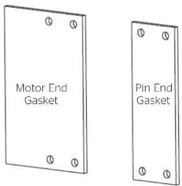
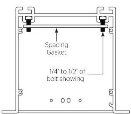
Place the two spacing gaskets (shown in Figure 5) on the bracket bolts with 14'' - 12'' of the bolts showing through the bottom (Figure 6).
-
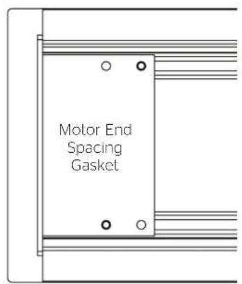
Slide the motor end spacing gasket until it makes contact with the end of the case (Figure 7).
-
Slide the pin end spacing gasket until it is approximately 1½ inches from the end of the case (Figure 8).
-
Carefully unpack the new ViewShare screen and roller assembly and set aside. Be sure to leave the packing paper on the roller.
NOTE: If your screen and roller assembly was ordered with a new motor, please proceed to "Installation of ViewShare Screen and Roller Assembly". If you are utilizing your existing motor, please continue to "Transfer of Existing Motor".
text_image
Circular Knockouts for CAT5 CableFigure 4
text_image
Motor End Gasket Pin End GasketFigure 5 - Spacing Gaskets
text_image
Spacing Gasket 1/4" to 1/2" of bolt showingFigure 6 Figure 7 Figure 8
text_image
Motor End Spacing Gasket
text_image
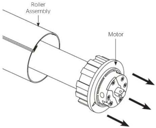
Pin End Spacing Gasket 1½ in.- Remove motor from the old screen and roller assembly and set aside (Figure 9).
NOTE: Try to avoid turning the rubber collar on the motor as you are pulling the motor out of the roller as this will change the limit switch settings.
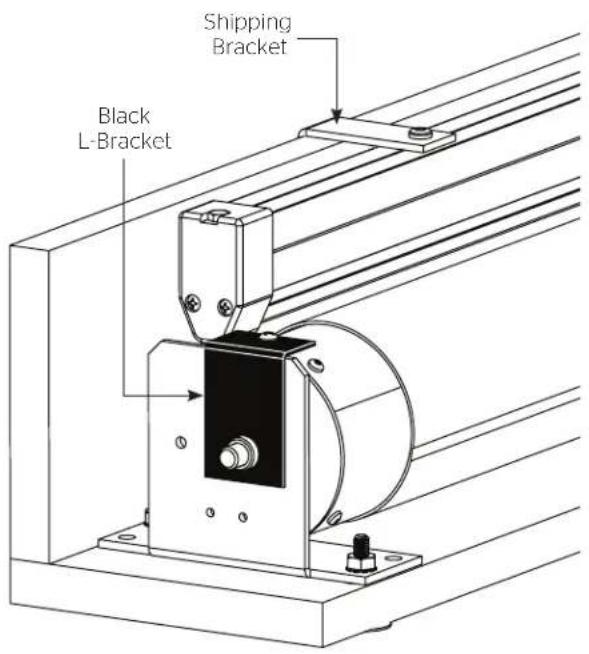
- Remove the black L-bracket from pin end of roller (Figure 11).
- Unscrew shipping brackets from slat and gently lay slat behind roller (Figure 10).
text_image
Roller Assembly MotorFigure 9
text_image
Shipping Bracket Black L-BracketFigure 10
- Completely remove both shipping brackets from the board.
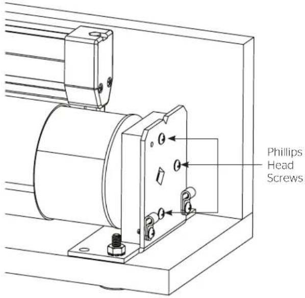
- Remove the three Phillips head screws from motor end bracket and remove wooden block (Figure 11).
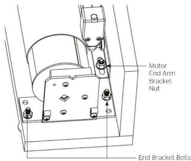
- On the ViewShare screen and roller assembly, loosen (but do not remove) the nut on the motor end arm bracket (Figure 12).
- Remove the two end bracket bolts securing the motor end bracket to the shipping board. Slide the bracket away from the end while supporting the roller (Figure 12).
text_image
Phillips Head ScrewsFigure 11
text_image
Motor End Arm Bracket Nut End Bracket BoltsFigure 12
- Carefully lift the roller above the mounting bracket and remove the wood block and plug from the end of the roller (Figure 13).
- Insert previously set aside motor into the ViewShare fabric and roller assembly.
NOTE: When transferring the existing motor into the roller, be careful to avoid unintentional damage to the screen and arm assemblies.
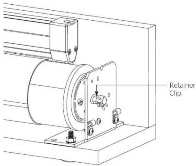
- Lower the roller, slide the bracket onto the motor end of roller and insert retainer clip (Figure 14).
- Align the motor end bracket using the mounting holes as a guide and lighten the motor end arm bracket nut (Figure 12).
- Re-attach the black L-bracket on the pin end of the roller (Figure 10).

text_image
Motor Plug Wood BlockFigure 13
text_image
Retainer ClipFigure 14
NOTE: The ViewShare screen and roller assembly, which includes brackets and arms, must be installed as a complete unit. Do not attempt to disassemble these components during installation.
- Remove two 14 - 20 nuts from pin end and motor end mounting brackets on the ViewShare screen and roller assembly shipping board (Figure 15).
NOTE: If you transferred you existing motor, the motor end nuts have already been removed.
- Remove screws from both L-brackets that hold the slat in place and carefully allow the slat to rest behind the ViewShare screen and roller assembly (Figure 15).
NOTE: If you transferred your existing motor, the L-brackets have already been removed.
-
Install ViewShare screen and roller assembly by placing the unit inside of case and secure motor end bracket by aligning bracket holes with bolts. Secure with two 14 - 20 nuts (Figure 16).
-
After the motor end is completed in Step 3, secure pin end by aligning bracket holes with bolts. Secure with two 14 - 20 nuts (Figure 16).
-
Once both ends are secured, ensure that the mounting brackets are parallel with both ends of the case (Figure 16).
NOTE: Brackets must be parallel with the case to ensure proper alignment of arms. Misalignment may cause damage to screen surface and arm assemblies.
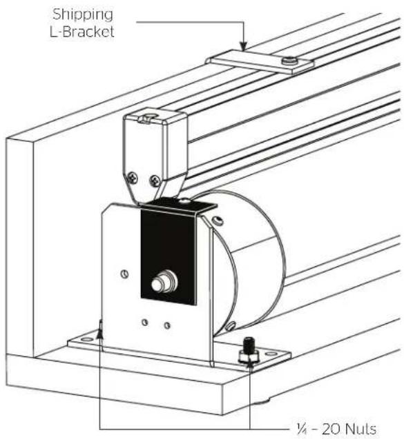
text_image
Shipping L-Bracket ¼ - 20 NulsFigure 15
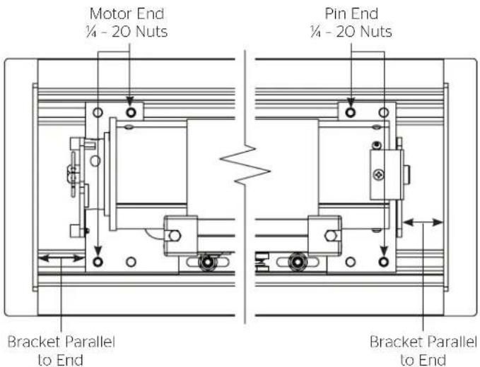
text_image
Motor End ¼ - 20 Nuts Pin End ¼ - 20 Nuts Bracket Parallel to End Bracket Parallel to EndFigure 16
- Remove black L-bracket on pin end of roller (Figure 17).
NOTE: If you transferred your existing motor, this bracket was removed in the previous section.
- Complete electrical hook-up by plugging in 3 or 4 wire motor connector and RJ-22/45 cable (if applicable) to the junction box. See Appendix A for motor type details. (Figure 18).
- Carefully remove paper and tape from roller assembly. DO NOT use knife or sharp object to cut tape or you will damage the screen.
- Test installation by running screen up and down a few times. Be prepared to stop screen should any objects obstruct the movement of the screen. To prevent damage to the motor, the standard duly cycle is 1 minute on and 3 minutes off.
NOTE: The up and down limits were pre-set by Da-Lite, but might have shifted during installation. If your screen and roller assembly needs adjustment, please see Appendix A for your motor type.
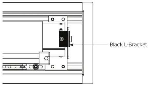
text_image
Black L-BracketFigure 17

text_image
Electrical ConnectionFigure 18
- Remove the USB to CAT5 extender labeled "Remote" from the shipping carton. At the motor end of the case, attach the USB cable coming from the ViewShare screen and roller assembly. On the other end of the USB to CAT5 extender, attach the CAT5 cable that was run through the circular knockout. Remove the non-adhesive side of the tape and carefully allow the USB to CAT5 extender to hang freely (Figure 19).
NOTE: The USB to CAT5 connection will allow the integrated ViewShare camera to interface with the other ViewShare hardware components installed in the Camera and Speakerphone Installation section.
- Re-install the access door. Before inserting completely, adhere the USB to CAT5 Extender to the inside of the access door out of view of the audience. Complete installation by sliding the access door into place and insert the screws into each end (Figure 20).

text_image
USB Cable USB to CAT5 Extender CAT5 CableFigure 19
text_image
Access Door ScrewsFigure 20
The following components are necessary and included for camera and speakerphone installation.
- Local CAT5 to USB Extender with Power Supply
- 6' USB Cable
- USB Speakerphone
- Powered USB Hub with 3' USB Cable
NOTE: A CAT5 cable is also required for installation. THE CAT5 CABLE IS NOT PROVIDED. The length of the CAT5 cable cannot exceed 200 feet.
For computer system requirements, specifications and troubleshooting, see the separate camera instruction located in the installation kit and the speakerphone instruction located inside the speakerphone box. Additionally, links to online assistance for each device are located in the Troubleshooting section of this instruction book.
Connections (see wiring diagram below)
- Connect your CAT5 cable to the local CAT5 to USB extender, which should be located near your computer. Connect the local CAT5 to USB extender power supply at this time.
NOTE: The CAT5 cable should only be connected between the ViewShare Advantage and the local CAT5 to USB extender. Do not connect to a server or network.
- Lower the ViewShare Advantage screen.
- Use the 6' USB cable to connect the local CAT5 to USB extender to the USB Hub.
- Connect the speakerphone to the powered USB hub.
- Connect the USB hub to your computer. Connect the USB hub power supply at this time.
NOTE: The computer may recognize the USB hub as a new component but it does not require any additional drivers. The USB hub does not need to be used if your computer has two open USB ports.

text_image
open USB ports. Laptop Video Cable to Projector 3' USB Cable 120 Volt Power Powered USB Hub Local CAT5 to USB Extender 120 Volt Power CAT5 Connection To Screen 6' USB Cable USB SpeakerphoneCamera and Speakerphone Setup
You are now ready to run the initial camera setup. The computer will recognize the camera as a new component and load the appropriate drivers. This can take up to several minutes and you may need to follow on-screen instructions. If the computer is using Windows 7 or later version, the computer will automatically detect the camera, choose the proper drivers, and install the drivers without your input. Once the green LED on the local CAT5 to USB extender is illuminated and the drivers are installed, you are ready to use the camera.
If the LED does not turn green after install, your computer may need to be restarted before the camera can be used. This could be a result of the type of operating system and other hardware/software installed, and is not necessarily a faulty device.
Selection the Camera and Speakerphone
- Open Lync, Skype or other compatible video calling software.
- Go to the options menu and select "C930e" under the video devices.
NOTE: The Da-Lite bowtie around the camera will glow when the camera is selected. If the window says "No camera detected", go back to the Connections section and check each step.
- In your software's options menu, select "Speakerphone 410" under the audio devices.
Installation is now complete and you are now ready to use your compatible video calling software.
Visit www.da-lite.com to find installation and troubleshooting tutorials. You will also find a link to Live Chat for interactive support.
You can contact us by email at info@da-lite.com or by phone at 800.622.3737 or 574.267.8101 with any additional troubleshooting questions.
Symptom Cause Solution
| Screen will not operate and motor does not hum. | Incorrect line voltage. | Verify 115-125V (or 220-240V). If insufficient voltage, rewire incoming electric line. |
| Blown fuse. Replace fuse. | ||
| Tripped circuit breaker. Reset circuit breaker. | ||
| No power to operating switch or junction. | Check above. Tighten all loose wire connections. Correct any improper connections. Down Position Check for power across black and white leads. Up Position Check for power across red and white leads. | |
| Screen will not operate and motor does not hum. Power at junction box. | Thermal overload tripped. Let motor cool down for 15 minutes. Try again. | |
| Broken wire in the "down" or "up" position. Check for continuity. Cut off old splice and reconnect. | ||
| Defective motor, limit switch or capacitor. Replace motor assembly. NOTE: Motor is a sealed assembly. | ||
| Capacitor burned out. Replace motor assembly. | ||
| Screen does not stop at correct position. | Limit switch out of adjustment. See Screen Adjustment section. | |
| Noise. NOTE: Screen will operate with a low pitched hum. | Squaking, rubber end plug rubbing on motor. Center roller in case. | |
| Grinding. Foreign object in screen rubbing on roller or fabric. | Remove. | |
| Gear noise. Replace motor assembly. | ||
| Coasting. | Defective brake. | Replace motor assembly. |
| Fabric hangs crooked. | Screen not installed properly. | Check for level and plumb. |
| Fabric has backed up inside case. | Adjust "down" limit switch slowly until roller is exposed and wrinkle comes out, then readjust for proper drop. | |
| Fabric is damaged. | Replace fabric. | |
| Metallic noise when screen finishes retracting. | Up limit is set too high. Solution: See Appendix A for limit switch adjustment. | Arms are not aligned properly. Solution: See Appendix B for arm adjustment. |
Camera Support: http://www.logitech.com/en-us/support/webcam-c930e-business?crid=405&osid=14&bit=64
Speakerphone Support: http://www.jabra.com/support/Jabra-SPEAK-410-MS_7410-109
TYPE 1 MOTOR
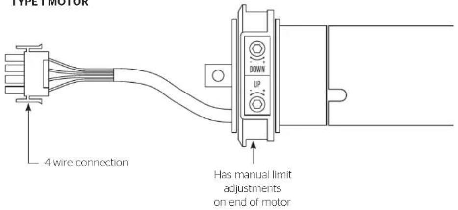
text_image
TYPE MOTOR 4-wire connection DOWN UP Has manual limit adjustments on end of motorTYPE 1 WALL SWITCH

natural_image
Simple line drawing of a double door with two circular buttons at the top (no text or symbols)Surface travel is stopped automatically in the fully opened and closed positions by limit switches that are properly adjusted at Da-Lite. Should it be necessary to adjust for more or less drop of screen, proceed in the following manner:
Remove two screws to remove access door.
NOTE: Use a screw driver or 5/32" Allen wrench to make adjustments.
Down Limit Adjustment - More Screen Drop
-
Place operating switch in "down" position.
-
When the screen stops, turn the "down" limit knob (Figure 22) one turn counterclockwise. Test by raising screen surface approximately two feet, then lower again. Repeat until desired screen surface position is attained.
AUTION: Do not adjust for more drop than what was ordered. At least 1-1/2 wraps of fabric must remain on the roller. This screen comes standard with 12" black at the top.
Down Limit Adjustment - Less Screen Drop
-
Raise screen surface approximately two feet above desired level.
-
Place operating switch in "off" position.
-
Turn the "down" limit knob (Figure 22) one turn clockwise. Test by raising screen surface approximately two feet, then lower again. Repeat until desired screen surface position is attained.
Up Limit Adjustment - Too Far Out of Case
-
Place operating switch in "up" position.
-
When the screen stops, turn the "up" limit knob (Figure 21) one turn counterclockwise. Test by lowering screen surface approximately two feet, then raise again. Repeat until slat bar is just in case.
- Lower screen surface approximately two feet below screen case opening.
- Place operating switch in "off" position.
- Turn the "up" limit knob (Figure 22) one turn clockwise. Test by lowering screen surface approximately two feet, then raise again. Repeat until slat bar is just in case.
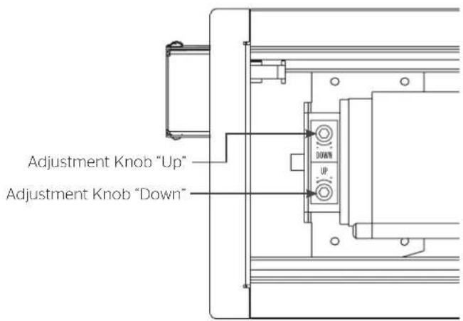
text_image
Adjustment Knob "Up" Adjustment Knob "Down"Figure 22
TYPE 2 MOTOR TYPE 2 WALL SWITCH
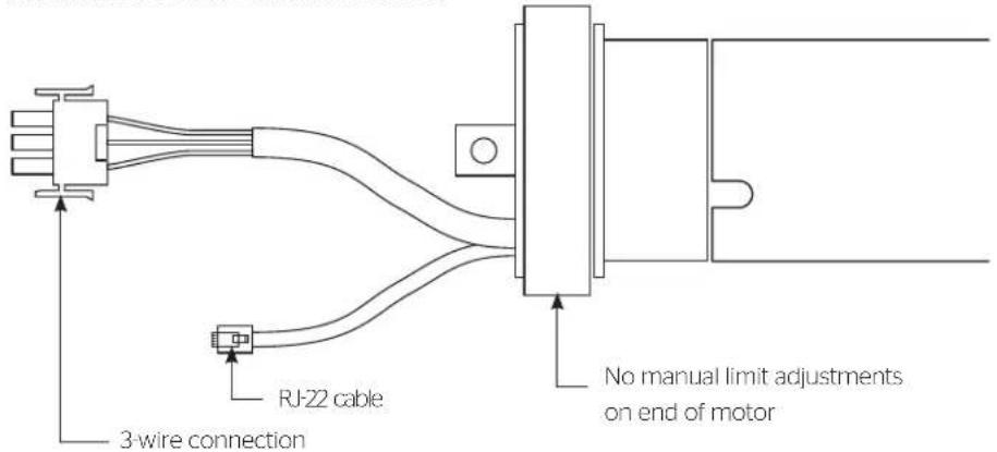
text_image
3-wire connection RJ-22 cable No manual limit adjustments on end of motor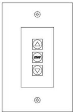
natural_image
Pure electrical circuit lines without any symbols- Remove the cover plate from the 3-button wall switch and remove the switch from the junction box.
- Locate small 3-position switch on back of wall switch.
- To adjust the down limit switch, slide the 3-position switch to the down position. Press and hold the down button to run the screen down to the desired stop position. Release the button to stop the screen. DO NOT PUSH THE STOP BUTTON.
HAUTION: Do not adjust for more drop than what was ordered. At least 1-1/2 wraps of fabric must remain on the roller. This screen comes standard with 12" black at the top.
ATTENTION! N'effectuez pas de réglage pour obtenir un déroulement supérieur à celui commandé. Au moins 1 à 1/2 tour de toile doit être maintenu sur le cylindre. Ce écran est doté de série d'une bande noire supérieure de 30,5 cm (12 po).
4. When the screen is in the desired down position, slide the 3-position switch to the off (center) position. The down limit switch is now set.
5. To adjust the up limit switch, slide the 3-position switch to the up position. Press and hold the up button to run the screen up to the desired stop position. Release the button to stop the screen. DO NOT PUSH THE STOP BUTTON.
CAUTION: Adjusting the limits by more than 6" can cause the screen surface to lose proper tensioning.
ATTENTION! Le fait d'ajouter plus de 15 cm (6po) aux interrupteurs de fin de course peut faire perdre la bonne tension à la surface de l'écran.
6. When the screen is in the desired up position, slide the 3-position switch to the off (center) position. The up limit switch is now set.
7. To test limit switch setting, make sure the 3-position switch is in the off (center) position. Press and release the up or down button on the wall switch to operate the screen.
- Replace switch and cover plate on the wall.
NOTE: If stop button is pressed, the wall switch will reverse direction. To correct this, press the stop button again. This will reset the switch. You will have to reset both the up and the down limit settings.
IMPORTANT NOTE: The wall switch is REQUIRED to make any limit switch adjustments, even if a third party control system is used. Therefore, it is advised to wire the switch or provide a 4-conductor connection that is accessible.
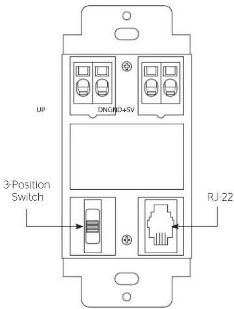
text_image
UP DNGND+5V 3-Position Switch RJ-22Back of Wall Switch
TYPE 3 MOTOR

text_image
RJ-45 cable 3-wire connection No manual limit adjustments on end of motorTYPE 3 WALL SWITCH
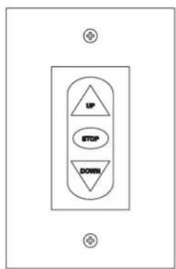
flowchart
graph TD
    A["UP"] --> B["STOP"]
    B --> C["DOWN"]
- Locate the wall switch and remove the cover plate from the wall switch and remove the switch from the junction box.
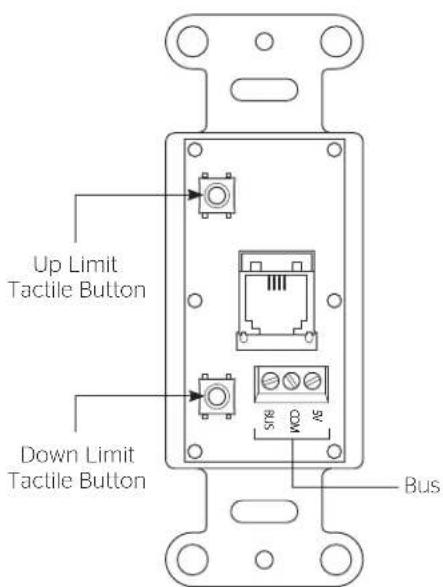
- Locate the two tactile buttons on the back of the switch. They are black round buttons on silver plates.
- To adjust the down limit switch, press and hold the down tactile button until the LED on the back of the switch turns solid red. This will put the motor in limit set mode. Turn the wall switch over and use the down button on the front of the switch. Press and hold the down button until the desired down position is reached. If you travel too far down, press the up button to move the screen upward. If you press and let go of either the up or down buttons, the motor will do a small jog in that direction for fine adjustment of the screen. Once the desired position is reached, turn the switch over; press and hold the down tactile button until the LED on back of switch blinks red twice. The down limit is now set.
AUTION: Do not adjust for more drop than what was ordered. At least 1-1/2 wraps of fabric must remain on the roller. This screen comes standard with 12" black at the top.
ATTENTION! N'effectuez pas de réglage pour obtenir un déroulement supérieur à celui commandé. Au moins 1 à 1/2 tour de toile doit être maintenu sur le cylindre. Ce écran est doté de série d'une bande noire supérieure de 30,5 cm (12 po).
NOTE: If the screen is in limit set mode and no buttons are pushed for 20 seconds, the LED on the back of the wall switch will turn off, the motor will return to run mode and no changes will be saved. If this occurs, return to step 3 for down limit adjustment or step 4 for up limit adjustment.
- To adjust the up limit switch, press and hold the up tactile button until the LED on the back of the switch turns solid green. This will put the motor in limit set mode. Turn the wall switch over and use the up button on the front of the switch. Press and hold the up button until the desired up position is reached. If you travel too far up, press the down button to move the screen downward. If you press and let go of either the up or down buttons, the motor will do a small jog in that direction for fine adjustment of the screen. Once the desired position is reached, turn the switch over; press and hold
the up tactile button until the LED on back of switch blinks green twice. The up limit is now set.
-
To test the limit switch settings, press and release the up or down buttons on the switch to operate the screen.
-
Replace the switch and cover plate on the wall.
IMPORTANT NOTE: The wall switch is REQUIRED to make any limit switch adjustments, even if a third party control system is used. Therefore, it is advised to wire the switch or provide a 3-conductor connection that is accessible.
text_image
Up Limit Tactile Button Down Limit Tactile Button BusBack of Wall Switch
- When screen is lowered approximately six inches below the case, the elbows of the arms should be horizontally aligned with each other (Figure 22)
- If the arms are not horizontally aligned loosen (but do not remove) the adjustment nut found inside the case behind the screen and roller assembly (Figure 23).
- With the adjustment nut loosened the arms can be adjusted inward and outward until horizontal alignment is correct.
- After arms have been properly aligned, secure the adjustment nut to complete arm adjustment.

text_image
Arm Elbows Horizontally AlignedFigure 22
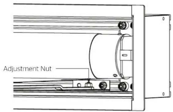
text_image
Adjustment NutFigure 23
LIMITED WARRANTY - VIEWSHARE PRODUCTS
Milestone AV Technologies LLC warrants its Da-Lite branded ViewShare products to the original purchaser only, to be free from defects in materials and workmanship in accordance with the following warranty term:
A period of five (5) years for the Advantage screen and related components; and
A period of three (3) years for the ViewShare camera and related components.
The foregoing warranty will commence upon the date of purchase by the original purchaser and is expressly contingent upon the products being properly operated according to Da-Lite's instructions and not damaged due to improper handling or treatment after shipment from the factory.
This warranty does not apply to equipment showing evidence of misuse, abuse or accidental damage, or which has been tampered with or repaired by a person other than authorized Da-Lite personnel.
Da-Lite's sole obligation under this warranty shall be to repair or to replace (at Da-Lite's option) the defective part of the merchandise. Returns for service should be made to your Da-Lite dealer. If it is necessary for the dealer to return the screen or part to Da-Lite, transportation expenses to and from Da-Lite are payable by the purchaser and Da-Lite is not responsible for damage in shipment. To protect yourself against damage or loss in transit, insure the product and prepay all transportation expenses.
TO THE MAXIMUM EXTENT PERMITTED BY APPLICABLE LAW, THIS WARRANTY IS IN LIEU OF ALL OTHER WARRANTIES, EXPRESS OR IMPLIED, INCLUDING WARRANTIES AS TO FITNESS FOR USE AND MERCHANTABILITY. Any implied warranties of fitness for use, or merchantability, that may be mandated by statute or rule of law are limited to the above warranty period. This warranty gives you specific legal rights, and you may also have other rights, which vary from state-to-state. TO THE MAXIMUM EXTENT PERMITTED BY APPLICABLE LAW, NO LIABILITY IS ASSUMED FOR EXPENSES OR DAMAGES RESULTING FROM INTERRUPTION IN OPERATION OF EQUIPMENT, OR FOR INCIDENTAL, DIRECT, OR CONSEQUENTIAL DAMAGES OF ANY NATURE.
In the event that there is a defect in materials or workmanship of a Da-Lite product, you may contact our Sales Partners at PO Box 137, Warsaw, IN 46581-0137, (574) 267-8101, (800) 622-3737.
IMPORTANT: THIS WARRANTY SHALL NOT BE VALID AND DA-LITE BRANDED PRODUCTS SHALL NOT BE BOUND BY THIS WARRANTY IF THE PRODUCT IS NOT OPERATED IN ACCORDANCE WITH THE DA-LITE WRITTEN INSTRUCTIONS.
Keep your sales receipt to prove the date of purchase and your original ownership.

A Milestone AV Technologies Brand
3100 North Detroit Street
Warsaw, Indiana 46582
P: 574.267.8101 or 800.622.3737
F: 574.267.7804 or 877.325.4832
E: info@da-lite.com
www.da-lite.com
DL-0205 (Rev. 2) 10.14
© 2014 Milestone AV Technologies LLC. Printed in U.S.A.