
093002 - Unknown Emga - Free user manual and instructions
Find the device manual for free 093002 Emga in PDF.

| Product Type | Electronic Device |
| Brand | Emga |
| Model | 093002 |
| Color | Black |
| Dimensions (W x D x H) | 15 x 10 x 5 cm |
| Weight | 0.3 kg |
| Power Source | AC 100-240V, 50/60Hz |
| Power Consumption | 10W |
| Input/Output Ports | USB, 3.5mm Audio Jack |
| Display | LED Indicator |
| Controls | Buttons, Knob |
| Connectivity | Bluetooth 5.0 |
| Functions | Playback, Volume Control, Power On/Off |
| Warranty | 2 Years |
| Included Accessories | Power Adapter, User Manual |
| Maintenance | Wipe with dry cloth; avoid moisture |
| Safety Certifications | CE, RoHS |
| Repairability | Modular design; spare parts available |
| Country of Origin | China |
Frequently Asked Questions - 093002 Emga
User questions about 093002 Emga
0 question about this device. Answer the ones you know or ask your own.
Ask a new question about this device
Download the instructions for your Unknown in PDF format for free! Find your manual 093002 - Emga and take your electronic device back in hand. On this page are published all the documents necessary for the use of your device. 093002 by Emga.
USER MANUAL 093002 Emga
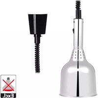
Longlife™ HEAT SHADE CE Heat Shade
Food warming luminaire specifi cation and installation instructions for:
L593 - popular . Gantry fitting
L596 - bell - Gantry fitting
L597 - ceiling suspension
L598 - rise and fall - ceiling suspension
GENERAL INFORMATION
Please read these instructions carefully. They will help you get the best out of your new LONGLIFE HEATSHADE and should be kept for your reference.
The LONGUIFE HEATSHADE is designed for use with any Edison screw Infra-Red (Hard Glass) heat lamp and is essential for maintaining the heat of servery food. The warming beam is directed to keep an adequate temperature and affording a pleasing illumination to display the food.
APPLICATIONS
For indoor use only, above hot food displays in:
Hotels, Restaurants, Cafeterias, Canteens, Pub Grub Services.
FEATURES OF THE HEAT LAMP SYSTEM
- Gives instant direct heat, no warm up period.
- Provides a penetrating warmth without congealing surfaces of sauces, gravies etc.
- Simple to install, either singly or in multiple units.
- Reduces wastage by keeping food and plates warm.
- Sale in use. Hard glass bulbs are resistant to thermal shock caused by accidental splashing.
MATERIALS AND FINISH
The shades are manufactured from high grade aluminium and electrostatically sprayed with thermoplastic lacquer for high heat, chemical and water resistance.
Available in the following finishes:
Brushed Copper
Brushed Aluminium
Brushed Brass
Brushed Bronze
ELECTRICAL CONNECTION
- All incoming cable installation should be heat resistant to 100 degrees Celsius.
- On no account should the prewired heat resistant cable be replaced with ordinary PVC insulated cable.
- All terminal connectors used must be heat resistant to 100 degrees Celsius and shrouded.
- Any channels or gantries used MUST BE EARTHED.
- The supply wiring must be routed from a fused source through a switch and then to the location you have selected.
- If a 13 amp (BS 1363) plug is used a 3 amp fuse must be fitted, or if any other type of plug is used a 5 amp must be fitted either in the plug or adaptor or at the Distribution Board.
- Ensure all ceiling roses are properly secured alter any height or tension adjustments are made. Do not leave electrical connections exposed.
- When stripping sheathing and insulation of cores leave the conductor exposed by approximately 6 mm.


COLOUR CODING OF WIRES
IMPORTANT:
The wires are coloured in accordance with the following code:
GREEN AND YELLOW EARTH
GENERAL ASSEMBLY INSTRUCTIONS - FOR ALL MODELS
WARNING: THESE LUMINAIRES ARE NOT SUITABLE FOR MOUNTING ON A NORMALLY FLAMMABLE SURFACE.
Please refer to diagrams attached: All models should be mounted so that the base of the shade is 330 mm to 450 mm above food, (see drawing). For multiple mounting suspend at 450 centres.
L593 and L596 Gantry Models - Main point of fixing is by means of a 10 mm brass all thread nipple and locknuts supplied.
a) Mark out Heatshades positions and drill clearance holes dia 13.5 mm fi xing holes and deburr sharp edges.
- Suitable gantries should measure 50 × 50 ~mm .
b) Assemblies units ensuring anti-rotation washer, Lock nut, thread reducer and cord grips are positioned correctly (see diagram attached).
c) Ensure any electrical connections are made in a suitable junction box mounted above the gantry


Model L597 (Which consists of items L5971, L5974, L5976 and L5977)

Model L598 (Which consists of items L5981, L5984, L5986, L5987, L5988 and L5989)
L597 Ceiling Suspension models - comprise of 2 metres of 3-core heat resisting black cable.
Cable grips are fitted to both ends.
a) Mark out and securely attach to ceiling.
Note! Type of ceiling construction will differ and a suitable fastener will need to be chosen by the litter / electrician on site,
(fi ttings not supplied)
b) To adjust the L597 model cable length, switch aft power and simply loosen the top cord grip and retighten to suit.


Brand : Emga
Model : 093002
Category : Unknown