SIAMES5 - Intercom JUNG - Free user manual and instructions
Find the device manual for free SIAMES5 JUNG in PDF.

User questions about SIAMES5 JUNG
0 question about this device. Answer the ones you know or ask your own.
Ask a new question about this device
Download the instructions for your Intercom in PDF format for free! Find your manual SIAMES5 - JUNG and take your electronic device back in hand. On this page are published all the documents necessary for the use of your device. SIAMES5 by JUNG.
USER MANUAL SIAMES5 JUNG
natural_image
Illustration of various household appliances including a thermometer, wall-mounted control panel, and solar panel (no text or symbols present)System Manual In-Home bus: Audio Issue 2016
SIEDLE Systemtechnik In-Home
Contents
| 1 In-Home bus: Audio | |
| System description 3 | |
| 2 Siedle Systemtechnik | |
| Jung indoor stations 3 | |
| 3 Safety remarks | |
| Danger 3 | |
| 4 Configuration, conductor lengths | |
| User assignment 1 | |
| Single line system 5 | |
| Single-line system with intercom function 7 | |
| Multiple line system | 8 |
| 5 In-Home: Audio users | |
| Door loudspeakers, call buttons | 10 |
| Power supply, line rectifiers | 12 |
| Switching, control | 13 |
| Software, PC interface, DoorCom | 14 |
| Bus indoor devices | 15 |
| Lung indoor stations | 17 |
| Accessories | 18 |
| 6 Installation | |
| General information | 20 |
| Bus call button module, bus line rectifier | 21 |
| Modular Jung indoor station | 22 |
| 6.1 Installation audio | |
| Siedle Vario | 24 |
| Siedle custom-FI door loudspeaker | 26 |
| Siedle Classic | 28 |
| Siedle Steel | 30 |
| Siedle Vario with Intercom functions | 32 |
| Siedle Vario 2 door stations | 34 |
| Multiple line system 36 | |
| Call via display call module | 38 |
| DoorCom Analog DCA 650... | 40 |
| 6.2 Siedle Systemtechnik installation | |
| Jung audio indoor station | 42 |
| Siedle and Jung indoor stations combined | 44 |
| 7 Programming | |
| Overview of functions | 46 |
| Remarks | 50 |
| 7.1 Programming - manual | |
| Activating the bus line rectifier | 51 |
| Activating the bus door loudspeaker | 52 |
| Activating the indoor devices | 53 |
| Activating Jung indoor services | 54 |
| Door call to siedle basic | 55 |
| Door call to bus telephone | 56 |
| Door call to bus handsfree telephone | 57 |
| Door call via the storey call button | 58 |
| Parallel door call 59 | |
| Internal call | 60 |
| Dialing the door station | 62 |
| Call differentiation of 2 door stations | 63 |
| Additional contact on the BSM 650... | 64 |
| Button of a bus telephone on the BSM 650- | 65 |
| Call button of a door station on the ESE 650... | 66 |
| Button of a bus telephone on the BSL 650... | 67 |
| Bus secondary signal unit BNS 750- | 68 |
| Call via DRM 612... | 69 |
| Door call to Jung indoor station | 70 |
| Parallel door call to Jung indoor station | 71 |
| Internal call between Jung indoor stations | 72 |
| 7.2 Programming - Plug+Play | |
| Basic | 74 |
| Example of a 4-family home | 75 |
| Procedure - Example | 77 |
| 7.3 Programming - with PC | |
| BPS 650... and FRI 602... USD 78 | |
| 8 Supplementary functions |
| Switching and control functions 79 |
| Door release ectuation 80 |
| Forale door call 82 |
| Storey cell parallel switching 86 |
| Supplementary contact, radiochina, pill or safeguard 87 |
| Staircase light/Outside light 88 |
| 9 Servicing |
| Rascart, exchange,operating mode 89 |
| 1FD displays LNG 650 ... 91 |
| Measured values 92 |
| 10 Glossary, Index 93 |
1 In-Home bus: Audio System description
2 Siedle Systemtechnik Jung indoor stations
3 Safety remarks Danger
Configuration "Single line"
The In-Home bus: The Audio system comprises a bus installation with a two-core line permitting the connection of up to 31 users, e.g. bus telephones, hands-free bus telephones, door stations or devices for switching and control functions. Technically speaking, one device can occupy more than one user. The line has its own bus line rectifier for central functions such as speech, door release or light switching. The two cores assume the dual functions of power supply and also transmission of audio, switching and control signals. Function points and branches are admissible at any optional position in the line. In order to connect more than 31 users, several Sedie In-Home: Audio lines can be interconnected.
Configuration "Multiple line"
In-Home: Audio "Single line" is restricted to 31 users. In order to connect more than 31 users, up to 15 lines can be coupled together. Each line requires its own bus line rectifier, junction points and branches are admistle at any optional position in the line.
"Siedle Systemtechnik" and the relevant logo are used to describe devices, components or systems which are not manufactured and designed by Siedle but are fitted with Siedle technology. The Systemtechnik logo guarantees technical compatibility with the Siedle system world. Products identified with "Siedle Systemtechnik" may therefore be used without restrictions as components of a Siedle communication system.
Jung indoor stations in switch design
Within the framework of a cooperation agreement with the company Jung, Siedle equips Jung indoor stations with "Siedle Systemtechnik". Indoor stations from Jung which bear the Systemtechnik logo on their components, their packaging or the product information, are fully compatible with Siedle technology. They are integrated in this manual as Siedle system components.
SIEDLE Systemtechnik In-Home

Mounting, installation and servicing work on electrical devices may only be performed by a suitably qualified electrician. Failure to observe this regulation could result in the risk of serious damage to health or fatal injury due to electric shocks.
- When working at the device, observe the remarks relating to mains cut-off.
- Observe the DIN EN 60065 standard! When establishing the electronic connection, observe the requirements of VDE 0805 or EN 60950.
• The building installation must include an all-pole mains switch with a contact separation of at least 3 mm. - Ensure maximum fusing of 16 A for the mains connection in the building installation.
- When planning large-scale (complex) systems, the distributor space required for the switch panel mounting devices must be taken into consideration in the distributor planning process.
- No external voltages >30 V AC/DC may be applied to bus users.
Devices with 230 V connection
In accordance with DIN VDE 0100 part 410, section 411.1.3 attention must be paid to ensuring a safe separation between system lines and the mains voltage, i.e. system and mains cores must not be permitted to touch! The system line cable (extra-low safety voltage) must be stripped back by the minimum possible.
4 Configuration, conductor lengths
User assignment
SIEDLE Systemtechnik
| Devices occupying 1 user | |
 | AIB 150...BTS 850...BTC 850...RFC 850...BNS 750... |
 | BSE 650...BEM 650...BSM 650... |
| Devices occupying 2 users | |
 | BT/M 650-CL A xx B-02STL8TLE 050... |
| Devices with variable user assignment (depending on programming) | |
| DCA 650... | |
| Devices occupying no users | |
| BNG 650...VNG 602...NG 602...TR 603... | |
| DIM 650...PR 602...USBRRM-A 050... | |
| Devices occupying 1 user | |
| SI 4 A...SI AM...SI AI... | |
| Devices occupying no users | |
| SITM 5073SITM 5093 | |
Devices with variable user assignment (depending on programming)
| DCA 650... | |
| Devices occupying no users | |
| BNG 650... | |
| VNG 602... | |
| NG 602... | |
| TK 603... | |
| BIM 650... | |
| PRI 602... USB | |
| BRMA 050... | |
Devices occupying 1 user
| SI 4 A... | |
| SI AM... | |
| SI AI... | |
| Devices occupying no users | |
| SI TM 5073 | |
| SI TM 5093 | |
Single line system
text_image
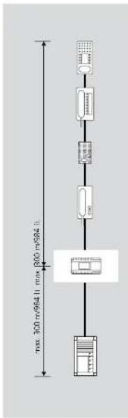
300 m/964.11 max 800 m/964.11Configuration of In-Home: Audio
The basic installation of In-Home-Bus: Audio taxes place as a single-line system. Within this line, the users are installed on the bus cores. A maximum of 31 users may be connected to one line. Users are classified as devices occupying an address within the bus. If more than 31 users are required, additional lines must be configured. Apart from a low exceptions, all the devices have an assigned address. Up to 15 lines each with 31 users can be configured in theory a maximum of 465 users).
Power supply
The nerve centre of any line is the bus line rectifier, which controls the entire function of the system. The bus cores are connected to the bus line rectifier.
Conductor material
Telecommunication or light current conductors can be used for installation.
J-Y(ST)Y twisted pair conductors, shielded
CAT Network cable A2Y(S1)2Y Buned telecommunication cable
YR Light current conductor 0.8 mm core diameter
The In-Home bus must be installed on one pair of cores when using J-Y(ST)Y, and when using a YR conductor, on two YR cores positioned side by side. Using J-Y(ST)Y conductors reduces the likelihood of interference.
Conductor length
• max. 300 m from the bus line rectifier to the most distant door station • max. 300 m from the bus line rectifier to the most distant bus telephone.
Conductor material JY(ST)Y or YR conductor with 0.6 mm diameter: - max. 150 m from the bus line rectifier to the most distant door station - max. 150 m from the bus line rectifier to the most distant bus telephone.
A maximum of 1500 m of installation cable may be laid within the line.
4 Configuration, conductor lengths Single line system

text_image
Side circuit 1 Side circuit 2 max. 300 m/984 ft. max. 300 m/984 ft. max. 300 m/984 ft. Door 1 Door 2Range
Cable material J-YISTY or
YR 0.8 mm
Distribution of the installation in the
sub-distribution board:
• Range to door station 1 and door
station 2 Bach max. 300 m
• Range to the most distant bus tele-
change to the most distant bus line phone in six-circuit 1, max. 3"CI 20
• Range to the most distant bus tele-
- Range to the most distant bus (in charge in six circuit 3 max. 750 m)
A maximum of 1500 m ol. insal
lation cable may be laid within the
np
Single-line system with intercom functions

text_image
max 300 m/94 ft max 300 m/94 ftConfiguration with intercom
function Using the hand-free bus telephone EFC 850-..., internal building communication can be supplemented to include additional convenience functions.
- Internal call with callback function
- Automatic call pick-up of internal calls
- Internal group call (max. 8 devices)
- Collective paging announcement (*only with supplementary supply and accessories)
For the paging announcement intercom function, an accessory is required in each hands-free bus telephone BFC 850-... This permits a direct voltage power supply directly to the hands-free bus telephone.
Using handsfree bus telephones, communication is possible without lifting the receiver. From a handsfree bus telephone, it is possible to call devices both with and without a receiver. Intercom functions are only possible within a line. Door calls have priority over internal calls.
In order to utilize the intercom functions, the system must be programmed at the PC.
Power supply
The nerve centre of any line is the bus line rectifier, which controls the entire function of the system. The bus cores are connected to the bus line rectifier.
^1 A supplementary power supply using a line rectifier or video line rectifier is only necessary in the case of collective paging announcements or parallel calls with more than two users.
Conductor material
Telecommunication or light current conductors can be used for installation:
LYISIY Twisted pair conductors, shielded
CAT Network cable
A2Y(S1)7Y Buried telecommunica
YR Light current conductor 0.8 mm core diameter
The In-Home bus must be installed on one pair of cores when using J-Y(S)Y, and when using a YR conductor, on two YR cores positioned side by side. Using J-Y(S)Y conductors reduces the likelihood of interference.
Conductor length
Conductor material : Y(STY or YR conductor with 0.8 mm diameter • max. 300 m from the bus line rectifier to the most distant door station
- max. 300 m from the bus line rectifier to the most distant bus telephone.
Conductor material J-Y(ST)Y or YR conductor with 0.6 mm diameter: max. 150 m from the bus line rectifier to the most distant door
- max. 150 m from the bus line rectifier to the most distant bus telephone.
A maximum of 1500 m of installation cable may be laid within the line.
4 Configuration, conductor lengths
Multiple line system

text_image
Line 1 Line 2 Line 15 max. 300 m/984 ft. max. 300 m/984 ft. max. 300 m/984 ft. max. 300 m/984 ft. Most claram SING-SNG (BarSBA) connection max. 200 m/984 ft.Configuration of the multiple
line system
A multiple line system comprises
Individual lines which are linked
together by two cores. The lines are connected at the bus line certify.
connected at the bus line rectifier using terminals for and the in my
using terminals 3a and 3b. in multi-tink line systems, door calls and
Uptle the systems, door cats and control functions are possible from
control functions are possible from one line to another.
Differentiation between
line 1 and
The lines are consecutively num-
bered with the address switch
"Adr." at the bus line rectifier. Up
to 15 lines can be connected via
the cores Sa and Sb. The bus supply
unit accessory ZBVG 650-... must
be plugged into one of the bus line
rectifiers within the overall system.
When installing, ensure that every
line is laid in its own cable.
Conductor length between
the lines
The admissible conductor lengths
within a line are identical to these in
a single line system. The conductor
length between the bus line recti-
fiers must also be taken into consid
eration. This may not be more than
300 m between the most distant bu
line rectifiers.
Functions applicable across
individual
Door calls, selective door dialling and
switching and control functions can
also be used across individual lines.
Internal speech communication and
call forwarding between users is only
possible within a line
5 In-Home: Audio users
Door loudspeakers, call buttons

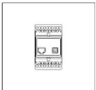
BTLM 650-04
Bus door loudspeaker module for In-Home bus. Loudspeaker and microphone integrated, illuminated light button, integrated door release contact (DR) Acoustic acknowledgement on pressing a button, can be activated if required with the B/P 650... contact load max. 15 V AC, 30 V DC, 2 A, switching time DR fixed at 3 seconds. Acoustic feedback when acquiring the call buttons.
BTM 650-01 to 04
Bus call button modules for In-Home bus 1-4 call buttons, integrated LED lighting. Connection by means of ribbon cable to the bus door loudspeaker. Supply to the LED lighting via terminal b and c with 12 V AC, current consumption 20 mA per bus call button module BTM 650-...
DRM 612-0
Display call module as an input device with 4-line display for placing door calls.
Indication of names in the display in alphabetical order.
The DRM 612-... can also be used in combination with the COM 611-...
In order to display the input via the COM 611-...

BTLE 051-03
Bus custom-fit door loudspeaker incl bus call button matrix for in-home bus. Integrated door release contact (DR). Max. load 15 V AC, 30 V DC, 2 A. Connection of existing call
BRMA 050-01
Bus call button matrix for the connection of existing call buttons to
THE LISTOR-FIN AUTHOR TITLE 05D.../ATLE 670-
Max. 160 call buttons can be con-

Siedle Classic
Door station with stainless steel front. Door loudspeaker and illuminated call buttons. Integrated door release contact (TÓ), contact load max. 15 V AC, 30 V DC, 2A, switching time TÓ fixed at 2 seconds. Current consumption for LED lighting of bell buttons, per button 5 mA, 12 V AC. Acoustic feedback when the call button is pressed.
Siedle Steel
Door station with stainless steel front, door loudspeaker and call buttons. Integrated door release contact (TO), contact load max. 15 V AC, 30 V DC, 2 A, switching time TO fixed at 3 seconds. Current consumption for LED lighting of bell buttons, per button 3 mA, 12 V AC. Acoustic feedback when the call button is pressed.
5 In-Home: Audio users Power supply, line rectifiers
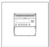
BNG 650-0
Bus line rectifier in a 9-grid housing Primary: 230 V AC, 50/60 Hz Secondary: 12 V AC, 1 A Door release contact 15 V AC, 30 V DC, 2 A, switching time fixed at 3 seconds.
Light contact 15 V AC, 30 V DC, 2 A, switching time 0.4 seconds, capable of being changed with bus programming software BPS 650-...
ZBVG 650-0
Bus supply unit accessory as a plug-in card for integration in bus line rectifier BNG 650-... or bus video line rectifier BVNG 650-... with 8-pin Western socket for connection of the programming interface PRI 602-... USB.
is required in systems with more than one line or for programming the in-nome bus via a Windows PC and PRI 602-... USA. Only one unit may be installed within the Siodle in Home bus.
NG 602-01
Line rectifier in switch panel housing for 1+n technology, and for power supply to supplementary components. Inclusive of function LEDs. Operating voltage:
230 V AC 4=10 %, 5060 Hz Typical current consumption: 41 VA Output voltage: 23.3 V DC, 12 V AC Output current: 0.3 A DC; 1.6 A AC
Amberd temperature
0℃ to 140℃
Horizontal pitch (HP): 6
Dimensions (mm) W x H x D

TR 603-0
Transformer in a 3-grid housing.
Primary: 230 V AC, 50/60 Hz
Secondary. 2 V AC, 1.3 A Additional supply for light on the
and thermal supply for lighting the nepal sons or doct diseases.

VNG 602-02
Video line rectifier in a 10-grid
housing.
Primary: 230 V AC, 50/60 Hz
Secondary: 30 N DC, 1.1 A Stadi-
Switching, control

BSM 650-02
Bus switching module in 3-grid housing. 4 integrated relays, each with a potential-free working contact. Actuation via the call buttons of the bus telephones or light button at the door station. Relay functions as a timer between 0.1 seconds and 12 seconds. Max. contact load 15 V AC, 30 V DC, 2 A, 12 V AC supply required, 250 mA.
BSE 650-0
Bus switching unit for mounting in 70 mm boxes. LED for status display and programming mode button. Actusion via the call buttons of the bus telephones or light button at the door station. The relay functions as a button, switch or timer for max. 19 minutes 59 seconds. Max. contact load 250 V AC/6 A.
BEM 650-0
Bus input module for mounting in a 55 junction box with an input for tripping switching functions/transmitting messages at the In-Home bus. Activation possible via potential-free contact or 4-30 V DC, 10 mA.
BIM 650-02
bus interface module in switch panel housing, used for connection between Siedle vario bus and Siedle In-Home bus. It is always required when a
5 In-Home: Audio users
Software, PC interface, DoorCom
PRI 602-0
Programming interface for connection of a Windows PC via serial interface to the Vario bus. The Vario bus is programmed using programming software PRS 602-... provided with the delivery. If the BIM 650-... is additionally used, the In-Home bus can also be programmed.
PRI 602-01 USB
Programming interface for connection of a Windows PC via USB port to the ZBVG 650-... interface. The ZBVG 650-... is plugged into bus line rectifier BNG/8VNG 650-... Commissioning, programming and servicing facility for the In-Home bus using IIP5 650-... software.

BPS 650-... from V2.50
Bus programming software for programming In-Home bus systems. For this, the programming interface FRI 602-... is also required in conjunction with a BIM 650-... or the FRI 602-... USB.
DCA 650-02
DoorCom-Analog for connection of one or more door stations to an analog PBX extension of a telephone system. Up to 31 call numbers can be stored. The call can be made
Bus indoor devices
AIB 150-0
Audio indoor station Siedle Basic: Handsfree station for surface mounting.
Entry-level device with all essential functions in the accustomed standard of Siecle quality. Minimized ergonomically optimized design with simple operation, clear symbolism and excellent acoustics.

BTS 850-02
Standard bus telephone. Connection
at bus cores Ta and Tb.
Functions:
- Calling, speech, door release and storey call
- Door release and light button
• internal speech communication
• 11 ringtones
• Call and voice volume adjustable
in 5 steps
- Muting button for ringtone
- Double assignment of the light
button and stretching button pass-
• Integration of ZAR 850, arrows.
sany possible
BTC 850-02
Deluxe bus telephone. Connection
at bus cores Ta and Tb
Functions:
- Calling, speech, door release and storey call
- Door release and light button
• Internal speech communication
• 11 ring tones
• Call and speech volume can be
changed in 5 steps
- Silencing button for the ring tone
- 7 keys for switching and control
functions with double assignment
activity
- PLED under the barriers for dis
play of switching statuses
• Integration of ZAR/2FS 850-
accessory possible
5 In-Home: Audio users Bus indoor devices
BFC 850-0
Deluxe handsfree bus telephone intercom. Connection at bus cores Ta and Tb.
- Calling, hands'ree/simplex communication, door release and storey calls
- Speed/control button
- Door release and light button
• Internal speech communication
- 11 ring tones
- Call and speech volume can be modified in 5 stages
- Mailing button for the ring tone - 7 keys for switching and control functions with double assignment facility
• Additional intercomfunctions possible
- Integration of ZARF/ZPSF 850-... accessory possible
BNS 750-02
Bus secondary signal unit, for signaling door and storey door calls in another room or corridor. Connection to In-Home bus: Audio Call volume steelessly adjustable up to max. 86 dB(A). Call differentiation for door calls and storey calls.

Jung indoor stations
Audio indoor station standard Audio indoor station design standard Calling, speech, door release, light, storey call, switching/control functions and internal communication. • Polarity reversal-proof 2-wire installation
• Connection for Siecle In-Home bus
- Connection for storey call button
- Call generator with IT call tone sequences, including chi-ma
- Mutang and status displays
SI AM ...
The audio module is the basic module of the modular structured flush mounted indoor station. This is where the Siecle In-Home bus is connected. If no call button module or video module is connected, the audio module functions as a secondary signal unit (bell).
SITM..5073
The standard call button module has 5 LEDs for display (e.g. door open) without additional wiring, one ready status using LED and one optical call display by means of a flashing LED at
SITM..5093
The universal call button module has 5 LLDs for display (e.g. door open) without additional wiring, one ready status using LED and one optical call display by means of a flashing LED at
tary power supply. This is required for operation of a video module, illumination of the inscription field in the universal call button module, and when connecting a second call button module. An additional
5 In-Home: Audio users Accessories
ZTS 800-01
Table-top accessory for telephones BTS/BFC 850- and HTS 811- for conversion from a wall to a table-top unit. Slip-proof console with 2 rubber feet but without UAE 8:8 junction box.

ZTC 800-0
Deluxe table-top accessory for the bus telephone BTC 850-... for conversion from a wall to a table top unit. Connection of the table top unit to an 8-pin telecom socket type UAE 8/8(8).
ZPS 850-0
Parallel switching accessory for integration into deluxe bus telephone BTC 850-... Circuit board for connection of an additional power supply. Required in case of manual programming from the third BTC 850-..., with PC programming from the fifth BTC 850-... Supply 20-30 V DC from NG 602-... or VNG 602-..., current consumption max. 100 mA

ZPSF 850-0
Parallel switching accessory for integration into deluxe handsfree bus telephone EFC 850-... Circuit board for connection of an additional power supply. When programming manually, required from the third EFC 850-... when programming by PC from the fifth EFC 850-... Supply 20-30 V DC from NG 602-... or VNG 602-... current consumption max. 100 mA. Required for the function parallel door call, collective paging announcement/internal group call in more than 2 bus telephones. When programming with BPS 650-... 4 bus telephones.
ZAR 850-0
Interfacing relay accessory for integration into bus telephone BTS/ BTC 850-... Universal switching relay for secondary signal unit, video interfacing or switching relay. Potential-free switching contact max. 15 V AC, 30 V DC, 1 A, switching time 0.4 seconds - 19 minutes Supply via the In-Home bus.
ZARF 850-0
Handfree interlocating relay accessory for integration in the handsfree bus telephone BFC 850-... Universal switching relay e.g. for secondary signal unit, video actuation or switching relay. Contact type: n.o. contact max. 15 V AC/30 V DC, 1 A Switching time: 0.4 sec to 19 min programmable using the bus programming software BPS 650-... V2.x
6 Installation
General information
Note
As in the as-delivered/de-energized status, the contact position of the bistable relay (contact S1/S1) cannot be defined, the bus supply to the device must be connected beforehand to ensure that the bistable relay functions correctly.
Consumers Voltage Current
| Door release 12 V AC appr. 600 mA | ||
| Variou bus call button module(BTM 650-01 to -04) | 12 V AC max. 20 mA | |
| Steel button illumination 12 V AC | 10-30 V DC | max. 3 mA |
| Classic button illumination CL ...-01 12 V AC | 10-30 V DC | max. 25 mA |
| max. 30 mA | ||
| Classic button illumination CL ...-02 12 V AC | 10-30 V DC | max. 5 mA |
| Models Terminal | Voltage | Current |
| assignment | ||
| RNG 650.... Ta, Tb 27.5 V DC 500 mA | ||
| b, c 17 V AC 1000 mA | ||
| NC 602.... +, -23.3 V DC 300 mA | ||
| b, c 12 V AC 1600 mA | ||
| TR 603.... b, c 12 V AC 1300 mA | ||
| TR 602.... b, c 12 V AC 2500 mA | ||
| VNG 602.... +M, -M | 30 V AC 1100 mA | |
Terminals
AIB 150-
BTS/BTC/BFC 850-...
Ta, 1b In-Home bus: Audio
LRT Storey call button
Optionally
Terminals
ZAR/ZARF 850-...
S1/S1 Potential-free contact 15 V AC, 30 V DC, 1 A
Bus call button module, bus line rectifier
text_image
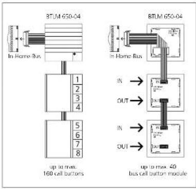
BTLM 650-04 In Home Bus 1 2 3 4 5 6 7 8 up to max. 160 cell buttons BTLM 650-04 in Home Bus IN → OUT → IN → OUT → up to max. 40 bus call button moduleBus call button module
Connection of the bus call button modules to the bus door loudspeaker via ribbon cable. The name plate lighting is supplied from the terminal clock of the BTLM 650-01. If there are more than 20 illuminated bus call button modules with LLD lighting (BTM 650-01, -02, -03, -04), these must be supplied via an additional transformer with 12 V AC if a door release is operated within the system.
text_image
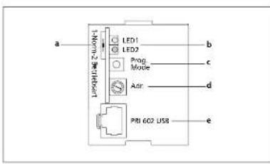
a Norm-2 be telesort LED1 LED2 Prog Mode ADR PRI 602 USB b c d eBus line rectifier
At bus line rectifier BNG 650—, the operating mode selector switch must be set to Norm in a new system (as-delivered status). If first series bus telechones are used within the line, (e.g. B. BTS/ BTC 750-0), the operating mode switch must be set to 1. For more information, see page 30
Using the "Adr." rotary switch, the address is set at the bus line rectifier. In single line systems, this is address 1 in the as-delivered status. This setting does not need to be altered. In multiple line systems, the bus line rectifiers are addressed in consecutive sequence.
a 1 = Reverse compatible (with BSG 650-...)
Standard = Operation as a new system 2 = Function identical to standard
b LED 1 = Operational LED LED 2 = Error LED
6 Installation
Modular Jung indoor station

flowchart
graph TD
    A["91AM"] --> B["91TN 5083"]
    B --> C["91TN 5073"]
    A --> D["TGP"]
    D --> E["91AM"]
    E --> F["91TN 5083"]
    F --> G["91TN 5073"]
Every module is mounted in a
flush-mounting junction box in compliance with DIN 49073. We recommend using a deep junction box for mounting. Mounting takes place using the provided support rings. Mounting can take place in combination or individually - horizontally or vertically.
The modules are interconnected using the supplied connecting tables.
Connection to the In-Horre bus takes place at the audio module. The universal call button module has one terminal for a supplementary power supply. This is required for operation of a video module,
Illumination of the description field in the universal call button module, and when connecting a second call button module. An additional call button module (standard or universal, max. 2 call button modules per indoor station) can be connected.
SI AI ... Audio indoor station Item no. Item designation

SI AM ... Audio module
SI TM .. 5073 Standard call button module
Audio combinations Item no. Item designation
| SI AM ... Audio module | |
| SI TM . 5073 Standard cell button module | |
| SI AM ... Audio module | |
| SI TM . 5093 Universal cell button module | |
| SI AM ... Audio module | |
| SI TM . 5093 Universal cell button module | |
| SI TM . 5073 Standard cell button module | |
| SI AM ... Audio module | |
| SI TM . 5093 Universal cell button module | |
| SI TM . 5093 Universal cell button module |
6.1 Installation audio
Siedle Vario
flowchart
graph TD
    A["Ta"] --> B["Tb"]
    B --> C["ERT"]
    C --> D["Ta"]
    D --> E["Tb"]
    E --> F["ERT"]
    F --> G["Ta"]
    G --> H["Tb"]
    H --> I["ERT"]
    I --> J["Ta"]
    J --> K["Tb"]
    K --> L["ERT"]
    L --> M["Ta"]
    M --> N["Tb"]
    N --> O["ERT"]
    O --> P["Ta"]
    P --> Q["Tb"]
    Q --> R["ERT"]
    R --> S["Ta"]
    S --> T["Tb"]
    T --> U["ERT"]
    U --> V["Ta"]
    V --> W["Tb"]
    W --> X["ERT"]
    X --> Y["Ta"]
    Y --> Z["Tb"]
    Z --> AA["ERT"]
    AA --> AB["Ta"]
    AB --> AC["Tb"]
    AC --> AD["ERT"]
    AD --> AE["Ta"]
    AE --> AF["Tb"]
    AF --> AG["ERT"]
    AG --> AH["Ta"]
    AH --> AI["Tb"]
    AI --> AJ["ERT"]
    AJ --> AK["Ta"]
    AK --> AL["Tb"]
    AL --> AM["ERT"]
    AM --> AN["Ta"]
    AN --> AO["Tb"]
    AO --> AP["ERT"]
    AP --> AQ["Ta"]
    AQ --> AR["Tb"]
    AR --> AS["ERT"]
    AS --> AT["Ta"]
    AT --> AU["Tb"]
    AU --> AV["ERT"]
    AV --> AW["Ta"]
    AW --> AX["Tb"]
    AX --> AY["ERT"]
    AY --> AZ["Ta"]
    AZ --> BA["Tb"]
    BA --> BB["ERT"]
    BB --> BC["Ta"]
    BC --> BD["Tb"]
    BD --> BE["ERT"]
    BE --> BF["Ta"]
    BF --> BG["Tb"]
    BG --> BH["ERT"]
    BH --> BI["Ta"]
    BI --> BJ["Tb"]
    BJ --> BK["ERT"]
    BK --> BL["Ta"]
    BL --> BM["Tb"]
    BM --> BN["ERT"]
    BN --> BO["Ta"]
    BO --> BP["Tb"]
    BP --> BQ["ERT"]
    BQ --> BR["Ta"]
    BR --> BS["Tb"]
    BS --> BT["ERT"]
    BT --> BU["Ta"]
    BU --> BV["Tb"]
    BV --> BW["ERT"]
    BW --> BX["Ta"]
    BX --> BY["Tb"]
    BY --> BZ["ERT"]
    BZ --> CA["Ta"]
Siedle Vario
Functional
Calling and speech between the door station and the connected bus indoor devices. Other bus telephones are not able to listen in to an existing call. Door release button for the door release function, light button for the light switching function. Connection of a store call button (ERT) for calling from an apartment door. Ring tones can be selected for calls from the front door, apartment door or internal calls. Connection of additional bus telephones or bus door loudspeakers possible at the In-Home bus without accessories.
Supplementary functions
- Internal speech communication between bus indoor devices is only possible internally within the same line.
- Switching and control functions are possible with the bus switching modules BSM/BSE/BLM 650-... feedback to the deluxe bus indoor devices can be programmed.
- Bus secondary signal unit BNS 750.... possible. - Parallel door and storey call Up to 4 AIR 150..../BTS/BTC/
BFC 850-... devices can be called simultaneously. With the parallel switching accessory in devices BTC, BFC 850-..., the number can be extended to a maximum of 8. Only possible within a line. For more information, see
page 82 - Selective dialling of the door station possible via additional free buttons.
Remarks
a) The BNG 650-... is able to supply 1 door release and max. 20 bus call button modules with LED lighting BTM 650-01, -02, -03 and -04. With more than 20 illuminated bus call button modules, an additional TR 603-... is required.
• Max. load of the bus door release contact in the bus line rectifier
BNG 650-... 15 V AC, 30 V DC, 2 A • Max. load of light contact in the bus line rectifier 15 V AC, 30 V DC, 2 A.
b) Door release 12 V AC, use at least 20 Ohm (e.g. TO 615-...).
For more information, see page 80
- Current consumption bus call button module 20 mA at terminal b/c. c) Conductor length bus indoor device – storey call button ERI max. 50 m.
6.1 Installation audio
Calling and speech between the door station and the connected bus indoor devices. Other bus telephones are not able to listen in to an existing call. Door release button for the door release function, light button for the light switching function. Connection of a skrony call button (FRT) for calling from an apartment door. Ring tones can be selected for calls from the front door, apartment door or internal calls. Connection of additional bus telephones or bus door loudspeakers possible at the In-Home bus without accessories.
Supplementary functions
- Internal speech communication between bus indoor devices is only possible internally within the same
- Switching and control functions are possible with the bus switching modules BSM/BSE/BEM 650..., feedback to the deluxe bus indoor devices can be programmed.
- Bus secondary signal unit BNS 750... possible.
- Parallel door and storey call Lip: to 4 AIR 150..../BTS/BTC/ BFC 850.... devices can be called simultaneously. With the parallel switching accessory in devices BT BFC 850..., the number can be extended to a maximum of 8. Only possible within a line. For more information, see
- Selective dialling of the door station possible via additional free buttons.
Remarks
a) The BNG 650.... can also supply the customer's own existing call buttons. A voltage of 12 V AC max. 400 mA is available for the lighting if a door release with an impedance of at least 20 Ohm is used. With a higher current consumption, an additional transformer must be used.
• Max. load of the bus door release contact in the bus line rectifier
BNG 650.... 15 V AC, 30 V DC, 2 A • Max. load of light contact in the bus line rectifier 15 V AC, 30 V DC, 2 A.
b) Door release 12 V AC, use at least 20 Ohm (e.g. TO 615-...). For more information, see page 80 c) Conductor length bus indoor device - storey call button ERI max. 50 m.
6.1 Installation audio
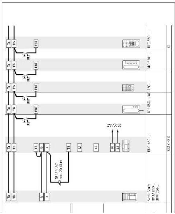
Siedle Classic

text_image
Tb Tb ERT Tb Tb ERT Tb Tb ERT Tb Tb ERT Tb Tb 1012 V AC min. 20 ohm c b To L U N LT C A D E 7.8 6 7.1 7.2 7.3 7.8 Single CASIC CL A P... Sterile CASIC call buttons B/C 690... B/C 690... A B 150... B/C 890... B/C 890... QSiedle Classic
Functional
Calling and speech between the door station and the connected bus indoor devices. Other bus telephones are not able to listen in to an existing call. Door release button for the door release function, light button for the light switching function. Connection of a store call button (ERT) for calling from an apartment door. Ring tones can be selected for calls from the front door, apartment door or internal calls. Connection of additional bus telephones or bus door loudspeakers possible at the In-Home bus without accessories.
Supplementary functions
- Internal speech communication between bus indoor devices is only possible internally within the same
possible internally within the same line.
- Switching and control functions are possible with the bus switching modules BSM/BSE/BEM 650..., feedback to the deluxe bus indoor devices can be programmed.
- Bus secondary signal unit BUS 750 possible
- Parallel door and storey call Lip to 4 AIR 150..../BTS/BTC/ BFC 850.... devices can be called simultaneously. With the parallel switching accessory in devices BTC/ BFC 850...., the number can be extended to a maximum of 8. Only possible within a line. For more information, see
page 82
- Selective dialling of the door station possible via additional free buttons.
Remarks
a) The BNG 650-... can supply 1 door release and a maximum of 80 buttons. With more than 80 call buttons, an additional transformer TR 603-... must be used. • Max. load of the bus door release contact in the bus line rectifier BNG 650-... 15 V AC, 30 V DC, 2 A • Max. load of light contact in the bus line rectifier 15 V AC, 30 V DC, 2 A.
b) Door release 12 V AC, use at least 20 Ohm (e.g. TO 615...). For more information, see page 80 c) Conductor length bus indoor device - storey call button ERT max. 50 m.
6.1 Installation audio
Siedle Steel
flowchart
graph TD
    A["Ta"] --> B["Tb"]
    B --> C["b"]
    C --> D["c"]
    D --> E["Tg 12 V AC min. 20 Chm"]
    E --> F["UT"]
    F --> G["U"]
    G --> H["L"]
    H --> I["N"]
    I --> J["L"]
    J --> K["3V A 057"]
    K --> L["BAG 650..."]
    L --> M["ab@ C4 da C"]
    M --> N["Stedle Steel"]
    style A fill:#f9f,stroke:#333
    style N fill:#ccf,stroke:#333
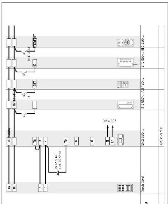
Siedle Steel
Functional
Calling and speech between the door station and the connected bus indoor devices. Other bus telephones are not able to listen in to an existing call. Door release button for the door release function, light button for the light switching function. Connection of a storey call button (ERT) for calling from an apartment door. Ring boxes can be selected for calls from the front door, apartment door or internal calls. Connection of additional bus telephones or bus door loudspeakers possible at the In-Home bus without accessories.
Supplementary functions
- Internal speech communication between bus indoor devices is only possible internally within the same
possible internally within the same line.
- Switching and control functions are possible with the bus switching modules BSM/BSE/BEM 650..., feedback to the deluxe bus indoor devices can be programmed.
- Bus secondary signal unit BNS 750... possible.
- Parallel door and storey call Up to 4 AIR 150.../BTS/BTC/ BFC 850... devices can be called simultaneously. With the parallel switching accessory in devices BTC, BFC 850..., the number can be extended to a maximum of 8. Only possible within a line. For more information, see
page 82
- Selective dialling of the door station possible via additional free buttons.
Remarks
a) The BNG 650-... can supply 1 door release and a maximum of 130 buttons. With more than 130 call buttons, an additional transformer IR 603-... must be used. • Max. load of the bus door release contact in the bus line rectifier BNG 650-... 15 V AC, 30 V DC, 2 A • Max. load of light contact in the bus line rectifier 15 V AC, 30 V DC, 2 A.
b) Door release 12 V AC, use at least 20 Ohm (e.g. T∅ 615...). For more information, see page 80 c) Conductor length bus indoor device - storey call button ERT max. 50 m.
6.1 Installation audio
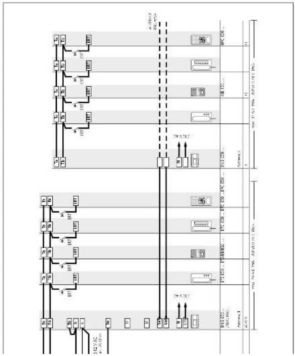
Siedle Vario with Intercom functions
text_image
M +400 +300 -300 +300 +300 +300 +300 +300 +300 +300 +300 +300 +300 +300 +300 +300 +300 +300 +300 +300 +300 +300 +300 22V AC 22V AC BMS 650... VME 602 1.7VAC 650... VME 650... 650... 650... 650... 650... 650... 650... 650... 650... 650... 650... 650... 650... 650... 650... 650... 650... 650... 650... 650... 650... 22V AC BMS 650... VME 602 1.7VAC 650... VME 650... 650... 650... 650... 650... 650... 650... 650... 650... 650... 650... 650... 650... 65Siedle Vario with
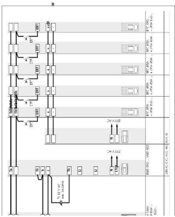
Intercom functions
Functional
Ceiling and speech between the door station and the connected bus indoor devices. Other bus telephones are not able to listen in to an existing call. Door release button for the door release function, light button for the light switching function. Connection of a skorry call button (ERT) for calling from an apartment door. Ring zones can be selected for calls from the front door, apartment door or internal calls. Connection of additional bus telephones or bus door loudspeakers possible at the In-Home bus without accessories.
Basic functions with all bus
indoor devices
- Internal speech communication between bus indoor devices is only possible internally within the same line.
- Switching and control functions are possible with the bus switching modules BSMUSEBLM 650-... feedback to the deluxe bus indoor devices can be programmed.
- Bus secondary signal unit
BNS 750... possible.
• Parallel door and storey call
Up to 4 AIB 150-.../BTS/BTC/ BFC 850-... devices can be called simultaneously. With the parallel switching accessory in devices BTC/ BFC 850-..., the number can be extended to a maximum of 8. Only possible within a line. For more information, see page 82
- Selective dialling of the door
station possible via additional free buttons.
Additional intercom functions
With handshree bus indoor devices BFC 850..., additional convenience functions are possible for internal communication.
- Internal call with callback function - Automatic call pick-up of internal calls
- Internal group call
• Collective paging announcement (*only with supplementary supply)
Remarks
a) The BNG 650... is able to supply 1 door release and max. 20 bus call button modules with LED lighting BTM 650-01, -02, -03 and -04. With more than 20 illuminated bus call button modules, an additional TR 603... is required. • Max. load of the bus door release contact in the bus line rectifier BNG 650... 15 V AC, 30 V DC, 2 A • Max. load of light contact in the bus line rectifier 15 V AC, 30 V DC, 2 A.
b) Door release 12 V AC, use at least 20 Ohm (e.g. TO 615-...).
For more
page 50 - Current consumption bus call button module 20 mA at terminal b/c. c) Conductor length bus indoor device - storey call button ERI
max. 50 m. x) Supplementary supply to hands-free bus telephones with direct voltage. Required for the function collective paging announcement or parallel door call. Direct voltage is connected at the parallel switching accessory 7PSF 850.... to terminals + and - A VNG 602.... can supply up to 8 BFC 850.... units with ZPSF 850....
System programming must be performed using the bus programming software BPS 650-...
6.1 Installation audio
Calling and speech between the door station and the connected bus indoor devices. Automatic assignment of the door release button to the door station from which the doorbell was last rung. Other bus telephones are not able to listen in to an existing call. Light button for the light switching function. Connection of a storey call button (FRT) for calling from an apartment door. Ring livers can be selected for calls from the front door, apartment door or internal calls. Connection of additional bus telephones or bus door loudspeakers possiole ct the In-Home bus without accessories.
Supplementary functions
- Internal speech communication between bus indoor devices is only possible internally within the same line.
- Switching and control functions are possible with the bus switching modules BSM/BSE/BLM 650-... feedback to the deluxe bus indoor devices can be programmed.
- Bus secondary sig BNS 750... possible.
- Parallel door and storey call Lip to 4 AIR 150..../BTS/BTC/
BFC 850-... devices can be called simultaneously. With the parallel switching accessory in devices BTC, BFC 850-..., the number can be extended to a maximum of 8. Only possible within a line. For more information, see
page 8
- Selective dialling of the door station possible via additional free buttons.
Remarks
a) The BNG 650-... is able to supply 1 door release and max. 20 bus call button modules with LED lighting BTM 650-01, -02, -03 and -04. With more than 20 illuminated bus call button modules, an additional TR 603-... is required.
• Max. load of the bus door release contact in the bus line rectifier
BNG 650-... 15 V AC, 30 V DC, 2 A • Max. load of light contact in the bus line rectifier 15 V AC, 30 V DC, 2 A.
b) Door release 12 V AC, use at least 20 Ohm (e.g. TO 615-...).
For more information, see page 80
• Current consumption bus call button module 20 mA at termina
b/c. c) Conductor length bus indoor
device – storey call button ERI max. 50 m.
6.1 Installation
Multiple line system
flowchart
graph TD
    A["Material 1"] --> B["Component 2"]
    B --> C{Process}
    C -->|Yes| D["Material 2"]
    C -->|No| E["Material 3"]
    D --> F["Component 1"]
    E --> G["Component 2"]
    F --> H["Output"]
    G --> H
    H --> I["Final Output"]

    subgraph Component 1
        J["Material 1"] --> K["Component 2"]
        L["Material 3"] --> M["Component 2"]
        N["Material 4"] --> O["Component 2"]
        P["Material 5"] --> Q["Component 2"]
        R["Material 6"] --> S["Component 2"]
        T["Material 7"] --> U["Component 2"]
        V["Material 8"] --> W["Component 2"]
        X["Material 9"] --> Y["Component 2"]
        Z["Material 10"] --> AA["Component 2"]
        AB["Material 11"] --> AC["Component 2"]
        AD["Material 12"] --> AE["Component 2"]
        AF["Material 13"] --> AG["Component 2"]
        AH["Material 14"] --> AI["Component 2"]
        AJ["Material 15"] --> AK["Component 2"]
        AL["Material 16"] --> AM["Component 2"]
        AN["Material 17"] --> AO["Component 2"]
        AP["Material 18"] --> AQ["Component 2"]
        AR["Material 19"] --> AS["Component 2"]
        AT["Material 20"] --> AU["Component 2"]
        AV["Material 21"] --> AW["Component 2"]
        AX["Material 22"] --> AY["Component 2"]
        AZ["Material 23"] --> BA["Component 2"]
        BB["Material 24"] --> BC["Component 2"]
        BD["Material 25"] --> BE["Component 2"]
        BF["Material 26"] --> BG["Component 2"]
        BH["Material 27"] --> BI["Component 2"]
        BJ["Material 28"] --> BK["Component 2"]
        BL["Material 29"] --> BM["Component 2"]
        BN["Material 30"] --> BO["Component 2"]
        BP["Material 31"] --> BQ["Component 2"]
        BR["Material 32"] --> BS["Component 2"]
        BT["Material 33"] --> BU["Component 2"]
        BV["Material 34"] --> BW["Component 2"]
        BX["Material 35"] --> BY["Component 2"]
        BZ["Material 36"] --> BQ
        CA["Material 37"] --> BQ
        CB["Material 38"] --> BQ
        CC["Material 39"] --> BQ
        DD["Material 40"] --> BE
        DE["Material 41"] --> BF
        EF["Material 42"] --> BG
        GF["Material 43"] --> BH
        GH["Material 44"] --> BI
        BI --> BJ
        BJ --> BK
        BK --> BL
        BL --> BM
        BM --> BN
        BN --> BO
        BO --> BX
        BX --> BY
        BY --> BA
        BA --> BB
        BB --> BC
        BC --> DA
        DA --> AE
        AE --> AF
    end

    subgraph Component 2
        AF
        AG
        AH
    end

    style Component 1 fill:#f9f,stroke:#333
    style Component 2 fill:#ccf,stroke:#333
Multiple line system
Functional
Calling and speech between the door station and the connected bus indoor devices. Automatic assignment of the door release button to the door station from which the doorbell was last rung.
Other bus telephones are not able to listen in to an existing call. Light button for the light switching function. Connection of a storey call button (ERT) for calling from an apartment door. Ring icons can be selected for calls from the front door, apartment door or internal calls. Connection of additional bus telephones or bus door loudspeakers possible at the In-Home bus without accessories.
In systems with more than 31 users, it is essential for a multiple line system to be configured. A multiple line system can also be used in order to form storey door stations or create functionally separate units such as a doctor's practice. Each line has its own spinch channel. Up to 160 users can be called from one door station. Instead of doorbell buttons, the call can also be picked via code lock module COM 611-... or display call module DRM 612-... In this case, up to 465 users can be called from one door station.
Supplementary functions
- Internal speech communication between bus indoor devices is only possible internally within the same line.
- Switching and control functions are possible with the bus switching modules BSM/BSE/BLM 650-... feedback to the deluxe bus indoor devices can be programmed.
- Bus secondary signal unit BNS 750... possible.
- Parallel door and storey call Up to 4 AIR 150.../BTS/BTC/
BFC 850-... devices can be called simultaneously. With the parallel switching accessory in devices BTC, BFC 850-..., the number can be extended to a maximum of 8. Only possible within a line. For more information, see
page 82 - Selective dialling of the door station possible via additional free buttons.
Remarks
a) The ENG 650-... is able to supply 1 door release and max. 20 bus call button modules with LED Lighting BTM 650-01, -02, -03 and -04.
With more than 20 illuminated bus call button modules, an additional TR 603-... is required.
• Max. load of the bus door release contact in the bus line rectifier
BNG 650-... 15 V AC, 30 V DC, 2 A • Max. load of light contact in the bus line rectifier 15 V AC, 30 V DC, 2 A.
b) Door release 12 V AC, use at least 20 Ohm (e.g. TO 615-...).
For more page 90
- Current consumption bus call button module 20 mA at terminal b/c.
c) Conductor length bus indoor device - storey call button ERT
max. 50 m. e) One bus line rectifier accessory ZBVG 65G-... only is required in the entire system.
f) If several BNG/BVNG 650... units are installed in one system, their addresses must differ.
6.1 Installation audio
Call via display call module
flowchart
graph TD
    A["Tu"] --> B["Tb"]
    B --> C["ENT"]
    C --> D["Switch"]
    D --> E["Transistor"]
    E --> F["Resistor"]
    F --> G["Ground"]
    H["Tu"] --> I["Tb"]
    I --> J["ENT"]
    J --> K["Switch"]
    K --> L["Transistor"]
    L --> M["Resistor"]
    M --> N["Ground"]
    O["Tu"] --> P["Tb"]
    P --> Q["ENT"]
    Q --> R["Switch"]
    R --> S["Transistor"]
    S --> T["Resistor"]
    T --> U["Ground"]
    V["Tu"] --> W["Tb"]
    W --> X["ENT"]
    X --> Y["Switch"]
    Y --> Z["Transistor"]
    Z --> AA["Resistor"]
    AA --> AB["Ground"]
Call via display call module
Functional
Calling and speech between the door station and the connected bus indoor devices. Dialling of bus telephones via the display call module. Selection of names takes place in alphabetical order.
Other bus telephones are not able to listen in to an existing call. Door release button for the door release function, light button for the light switching function. Connection of a storey call button (ERT) for calling from an apartment door. Ring tones can be selected for calls from the front door, apartment door or internal calls. Connection of additional bus telephones or bus door loudspeakers possible at the In-Home bus without accessories.
Supplementary functions
- Internal speech communication between bus indoor devices is only possible internally within the same line.
- Switching and control functions are possible with the bus switching modules BSM/BSE/BEM 650-... feedback to the deluxe bus indoor devices can be programmed.
- Bus secondary sig BNS 750... possible
- Parallel door and storey call Up to 4 AIR 150.../BTS/BTC/
BFC 850..., devices can be called simultaneously. With the parallel switching accessory in devices BTC/BFC 850..., the number can be extended to a maximum of 8. Only possible within a line. For more information, see
- Selective dialling of the door station possible via additional free buttons.
Remarks
a) The BNG 650-... is able to supply 1 door release and max. 20 bus call button modules with LED lighting BTM 650-01, -02, -03 and -04. With more than 20 illuminated bus call button modules, an additional TR BC3-... is required.
- Max. load of the bus door release contact in the bus line rectifier
BNG 650-... 15 V AC, 30 V DC, 2 A • Max. load of light contact in the bus line rectifier 15 V AC, 30 V DC, 2 A
b) Door release 12 V AC, use at least 20 Ohm (e.g. TÜ 615-...).
For more information, see page 80
- Current consumption bus call button module 20 mA at termin b/c.
c) Conductor length bus indoor device - storey call button ERT
f) Names are programmed using a Windows PC via programming interface PRI 602.... The software PR5 602... first needs to be installed.
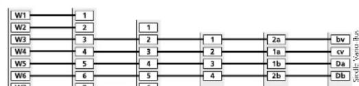
flowchart
graph TD
    W1 --> 1
    W2 --> 2
    W3 --> 3
    W4 --> 4
    W5 --> 5
    W6 --> 6
    1 --> 2
    2 --> 3
    3 --> 4
    4 --> 5
    5 --> 4
    1 --> 2a
    2 --> 1a
    3 --> 1b
    4 --> 2b
    2a --> bv
    1a --> cv
    1b --> Da
    2b --> Db
6.1 Installation audio
DoorCom Analog DCA 650-...
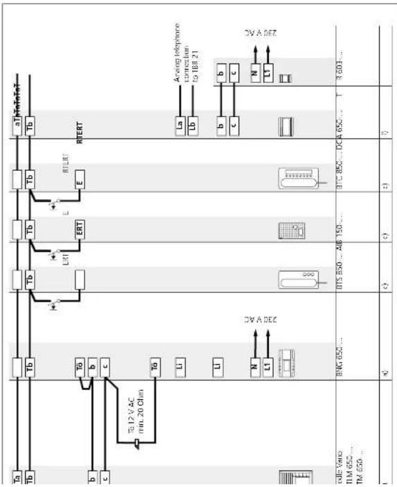
flowchart
graph TD
    A[" meters"] --> B[" relays "]
    B --> C[" L1 "]
    B --> D[" L2 "]
    B --> E[" L3 "]
    B --> F[" L4 "]
    B --> G[" L5 "]
    B --> H[" L6 "]
    B --> I[" L7 "]
    B --> J[" L8 "]
    B --> K[" L9 "]
    B --> L[" L10 "]
    B --> M[" L11 "]
    B --> N[" L12 "]
    B --> O[" L13 "]
    B --> P[" L14 "]
    B --> Q[" L15 "]
    B --> R[" L16 "]
    B --> S[" L17 "]
    B --> T[" L18 "]
    B --> U[" L19 "]
    B --> V[" L20 "]
    B --> W[" L21 "]
    B --> X[" L22 "]
    B --> Y[" L23 "]
    B --> Z[" L24 "]
    B --> AA[" L25 "]
    B --> AB[" L26 "]
    B --> AC[" L27 "]
    B --> AD[" L28 "]
    B --> AE[" L29 "]
    B --> AF[" L30 "]
    B --> AG[" L31 "]
    B --> AH[" L32 "]
    B --> AI[" L33 "]
    B --> AJ[" L34 "]
    B --> AK[" L35 "]
    B --> AL[" L36 "]
    B --> AM[" L37 "]
    B --> AN[" L38 "]
    B --> AO[" L39 "]
    B --> AP[" L40 "]
    B --> AQ[" L41 "]
    B --> AR[" L42 "]
    B --> AS[" L43 "]
    B --> AT[" L44 "]
    B --> AU[" L45 "]
    B --> AV[" L46 "]
    B --> AW[" L47 "]
    B --> AX[" L48 "]
    B --> AY[" L49 "]
    B --> AZ[" L50 "]
    B --> BA[" L51 "]
    B --> BB[" L52 "]
    B --> BC[" L53 "]
    B --> BD[" L54 "]
    B --> BE[" L55 "]
    B --> BF[" L56 "]
    B --> BG[" L57 "]
    B --> BH[" L58 "]
    B --> BI[" L59 "]
    B --> BJ[" L60 "]
    B --> BK[" L61 "]
    B --> BL[" L62 "]
    B --> BM[" L63 "]
    B --> BN[" L64 "]
    B --> BO[" L65 "]
DoorCom Analog DCA 650-...
Functional
Calling and speech between the door station and the connected arb telephones of a telephone system. The DoorCom-Analog DCA 650-... is able to forward the call from up to 31 bell buttons to a telephone system. The DCA 650-... calls the PBX extensions of the telephone system using dual-lone multiple frequency dialling DTMF. Other bus telephones are not able to listen in to an existing call. Door release and light switching functions are possible via DTMF to connected arb telephones of the telephone system.
Supplementary functions
It is also possible to connect bus telephones to the door station. Switching and control functions can be triggered via the DCSF 600-... For this, the connected telephones of the telephone system call the PDX extension of the DCA 650-... and execute the function by means of OTMF dialing.
Remarks
a) The BNG 650-... is able to supply 1 door release and max. 20 bus call button modules with LED lighting BTM 650-01, -02, -03 and -04. With more than 20 illuminated bus call button modules, an additional IR 603-... is required.
- Max. load of the bus door release contact in the bus line rectifier BNG 650-... 15 V AC, 30 V DC, 2 A - Max. load of light contact in the bus line rectifier 15 V AC, 30 V DC, 2 A
b) Door release 12 V AC, use at least 20 Ohm (e.g. TÖ 615-...). For more information, see page 80
- Current consumption bus call button module 20 mA at terminal b/c. c) Conductor length bus indoor device – storey call button ERT max. 50 m.
f) If the predecessor model DCA 650-0 is used, the operating mode switch of the BNG 650-... must be in position 1. The maximum distance of the DCA 650-... from the TR 603-... is 20 m. If several DCA 650-... units are used within a system, each DCA 650-... must be supplied by its own transformer.
6.2 Siedle Systemtechnik installation
Jung audio indoor station
flowchart
graph TD
    A["T0M"] --> B["ELT"]
    B --> C["ERT"]
    C --> D["280V AC"]
    D --> E["N L1"]
    D --> F["M"]
    D --> G["LM"]
    D --> H["+"]
    D --> I["-M"]
    D --> J["+"]
    D --> K["+"]
    D --> L["+"]
    D --> M["+"]
    D --> N["+"]
    D --> O["+"]
    D --> P["+"]
    D --> Q["+"]
    D --> R["+"]
    D --> S["+"]
    D --> T["+"]
    D --> U["+"]
    D --> V["+"]
    D --> W["+"]
    D --> X["+"]
    D --> Y["+"]
    D --> Z["+"]
    D --> AA["+"]
    D --> AB["+"]
    D --> AC["+"]
    D --> AD["+"]
    D --> AE["+"]
    D --> AF["+"]
    D --> AG["+"]
    D --> AH["+"]
    D --> AI["+"]
    D --> AJ["+"]
    D --> AK["+"]
    D --> AL["+"]
    D --> AM["+"]
    D --> AN["+"]
    D --> AO["+"]
    D --> AP["+"]
    D --> AQ["+"]
    D --> AR["+"]
    D --> AS["+"]
    D --> AT["+"]
    D --> AU["+"]
    D --> AV["+"]
    D --> AW["+"]
    D --> AX["+"]
    D --> AY["+"]
    D --> AZ["+"]
    D --> BA["+"]
    D --> BB["+"]
    D --> BC["+"]
    D --> BD["+"]
    D --> BE["+"]
    D --> BF["+"]
    D --> BG["+"]
    D --> BH["+"]
    D --> BI["+"]
    D --> BJ["+"]
    D --> BK["+"]
    D --> BL["+"]
    D --> BM["+"]
    D --> BN["+"]
    D --> BO["+"]
    D --> BP["+"]
    D --> BQ["+"]
    D --> BR["+"]
    D --> BS["+"]
    D --> BT["+"]
    D --> BU["+"]
    D --> BV["+"]
    D --> BW["+"]
    D --> BX["+"]
    D --> BY["+"]
    D --> BZ["+"]
    D --> CA["+"]
    D --> CB["+"]
    D --> CC["+"]
    D --> CD["+"]
    D --> CE["+"]
    D --> CF["+"]
    D --> CG["+"]
    D --> CH["+"]
    D --> CI["+"]
    D --> CJ["+"]
    D --> CK["+"]
    D --> CL["+"]
    D --> CM["+"]
    D --> CN["+"]
    D --> CO["+"]
    D --> CP["+"]
    D --> CZ["+"]
    D --> DA["+"]
    D --> DB["+"]
    D --> DC["+"]
    D --> ED["+"]
    D --> FD["+"]
    D --> DG["+"]
    D --> DH["+"]
    D --> DI["+"]
    D --> DJ["+"]
    D --> DK["+"]
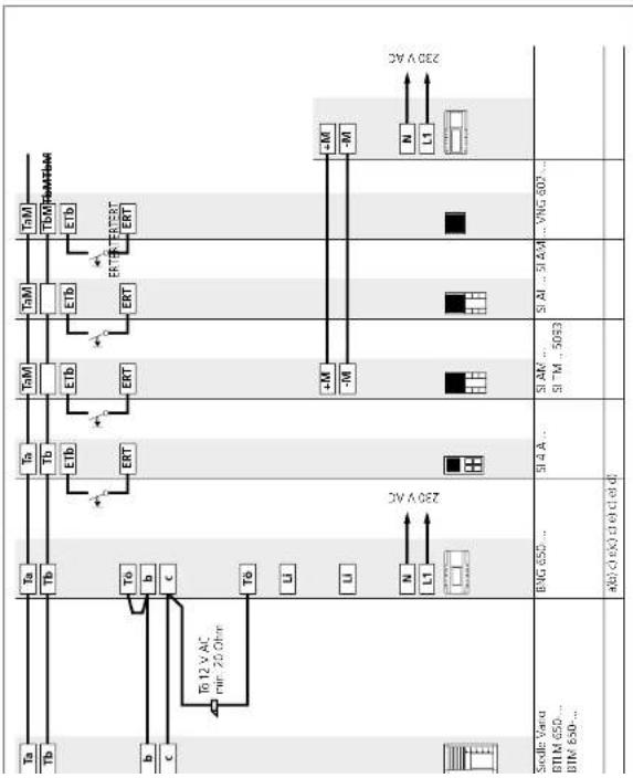
Jung audio indoor station
Calling and speech between door stations and the connected Jung indoor devices. Automatic assignment of the door release button to the door station from which the doorbell was last rung. Other bus telephones are not able to listen in to an existing call. Door release button for the door release function, light button for the light switching function. Connection of a story call button (FERT) for calling from an apartment door. Ring tones can be selected for calls from the front, door, apartment door or internal calls. Connection of additional bus telephones or bus loudspeakers possible at the In-Home bus without accessories.
Supplementary functions
- Internal speech communication between bus indoor devices is only possible internally within the same line.
- Switching and control functions are possible with the bus switching modules BSMMSBBLM 650-... feedback to the deluxe bus indoor devices and Jung indoor devices can be programmed.
- Bus secondary signal unit BNS 750... possible.
- Parallel door and storey c
Up to 4 audio indoor stations can be called simultaneously via one bell button without an additional supply. Only possible within a line. For more information, see page 82 - Selective dialling of the door station possible via additional free buttons.
Remarks
a) The BNG 650-... is able to supply 1 door release and max. 20 bus call button modules with LED lighting BTM 650-01, -02, -03 and -04. With more than 20 illuminated bus call button modules, an additional TR 603-... is required.
- Max. load of the bus door release contact in the bus line rectifier BNG 650.... 15 V AC, 30 V DC, 2 A
- Max. load of light contact in the bus line rectifier 15 V AC, 30 V DC, 2 A.
b) Door release 12 V AC, use at least 20 Ohm (e.g. TÖ 615-...)
For more information, see page 80
Current consumption bus call button module 20 mA at terminal b/c.
c) Conductor length bus indoor device – storey call button ERT max. 50 m.
d) The Jung Universal call button module can be supplied with a direct voltage of (22–30 V DC, 170 mA). The VNG 602-... can be used for this purpose.
e) The Jung audio module is connected directly to the In-Home bus audio.
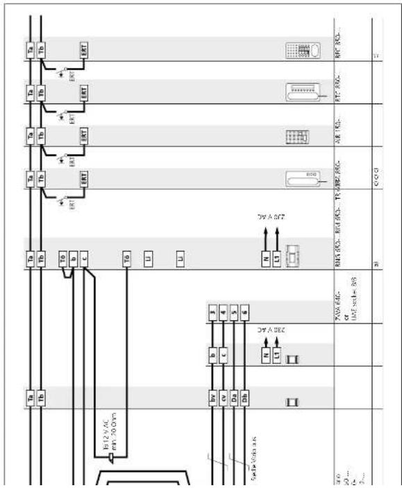
6.2 Siedle Systemtechnik installation
Siedle and Jung indoor stations combined

text_image
Tn Tb ETB ERT TcM TOM ETB ERT Ta Tb ERT Ta Tb ERT Ta Tb ERT Ta Tb ERT Ta Tb ERT Ta 12 V AC pin 20 Ohm To 12 V AC to 20 Ohm To 650... BVG 650... BVG 650... SIAI... SIAA... 20V AC 40(10) CSiedle and Jung indoor stations
Calling and speech between door stations and the connected Jung indoor devices. Automatic assignment of the door release button to the door station from which the doorbell was last rung. Other bus telephones are not able to listen in to an existing call. Door release button for the door release function, light button for the light switching function. Connection of a sticky call button (FRT) for calling from an apartment door. Ring hinges can be selected for calls from the front; door, apartment door or internal calls. Connection of additional bus telephones or bus door loudspeakers possible at the In-Home bus without accessories.
Supplementary functions
- Internal speech communication between bus indoor devices is only possible internally within the same line.
- Switching and control functions are possible with the bus switching modules BSMWSE/BLM 650-... feedback to the deluxe bus indoor devices and Jung indoor devices can be programmed.
- Bus secondary signal unit
- Parallel door and storey call
Up to 4 audio indoor stations can be called simultaneously via one bell button without an additional supply. Only possible within a line. For more information, see page 82.
- Selective dialling of the door station possible via additional free buttons.
Remarks
a) The BNG 650... is able to supply 1 door release and max. 20 bus call button modules with LED lighting BTM 650-01, -02, -03 and -04. With more than 20 illuminated bus call button modules, an additional IR 603... is required. • Max. load of the bus door release contact in the bus line rectifier BNG 650... 15 V AC, 30 V DC, 2 A • Max. load of light contact in the bus line rectifier 15 V AC, 30 V DC, 2 A.
b) Door release 12 V AC, use at least 20 Ohm (e.g. TÖ 615-...) For more information, see page 80
Current consumption bus call button module 20 mA at terminal b/c. c) Conductor length bus indoor device – storey call button ERT max. 50 m.
e) The Jung audio module is connected directly to the In-Home bus audio.
7 Programming
Overview of functions
Functions with Siedle In-Home and
programming possibilities. Temrs used in the table are explained in
used in the table are explained in data ^7 on the next page.
detail on the next page.
- not available
- Plug+Play programming
√07- Manual programming
√√• PC programming
| Basic functions | ||||
| AIB 150... | BTS 850... | BTC 850... | BFC 850... | |
| Door call | * / * * * * / * * * * / * * * * / * * * | |||
| -Storey call | ||||
| -Door release button | ||||
| -Light button | ||||
| -Call silencing and display(Functione following installation) | ||||
| Dialling last door(Functione following installation) | - / / * - / / * - / / * - / / * | |||
| Call tone configurationSetting at the bus indoor device | - / / * - / * * - / * * * - / * * | |||
| Supplementary functions | ||||
| BSE Groups - / * * - / * * - / * * - / * * Group formation - / * * - / * * - / * * - / * * Internal call - / * * - / * * - / * * Camera step - - - | ||||
| Secondary signal unit - / * * - / * * - / * * - / * * Parallel device - / * * - / * * - / * * - / * * Status display (via LED) -- - / * * - / * * Control function - / * * - / * * - / * * - / * * Door dialing - / * * - / * * - / * * | ||||
| Door clock acceptance | - / * * - / * * - / * * Door call forwardingTime for light contact - / * * - / * * - / * * - / * * Second button level | - / * * - / * * - / * * - / * * | ||
| Intercom functions | ||||
| Internal group call | - / * * - / * * - / * * Collective announcement -- - / * * Automatic call acceptance | - / * * Set cell-back | - / * * | - / * * |
7 Programming Overview of functions
Dialling last door
The door station from which the last door call was placed can be dialled by double clicking the light button.
Automatic call acceptance
The handsfree indoor device automatically picks up incoming internal calls and switches on the speech connection.
BSE Groups
Several bus switching units are assigned to a group. This allows several BSE 650-... units to be executed simultaneously with one switching contact, e.g. shutter control.
Storey call
The storey call button (ERT) is used to call into the apartment from an apartment door. Application e.g. apartment building with 4 apartments and a common staircase. Storey call buttons are installed in front of every apartment front door.
Group formation
Several bus indoor devices are assigned to a group. This allows up to 8 bus indoor devices to be called with one button. A bus indoor device can belong to up to 4 different groups.
Intercom
The term Intercom denotes internal communication within one building. Using handsfree bus indoor devices, intercom communication is particularly simple and convenient, as it does not require a receiver to be lifted.
Internal call
Bus indoor devices can place calls to each other using the buttons. Using the standard indoor device, 4 users can be called. The deluxe indoor devices are able to call up to 14 users. Internal calls are only possible within a line.
Internal group call
Internal call to several indoor devices simultaneously. The device which initially establishes the connection has the call.
Light button
In the as-delivered status, the light button in the bus indoor device switches the contact in the bus line rectifier for 0.4 seconds. Using
the bus programming software BPS 650-... this time can be altered. The function of the light button can be reprogrammed, e.g. for internal calls.
Secondary signal unit
The interfacing relay accessory is available for bus telephones BTS/ BTC 850.... for actuating a signaling device or a lamp. For BTC 850.... use accessory ZARF 850.... A bus secondary signal unit BNS 750.... can be programmed in parallel to a bus indoor device.
Max. 8 bus indoor devices can ring simultaneously when actuating a doorbell button.
Call silencing and display
The call can be switched off at the bus indoor devices. Deactivation is signaled at the device.
Call tone configuration
At each bus indoor device, different call tones can be selected for every call type (door call, internal call, storey call).
Receive callback
If you are available to accept an internal call, a callback can be requested. This is optically signalled at the deluxe indoor device. This function can be programmed at all deluxe bus indoor devices.
Set call-back
If you make an internal call and the user does not pick up, you can request a callback. To do this, press the flashing button twice.
Collective announcement
Paging announcement to one or more deluxe handsfree devices. Can be used for instance for making an announcement in a waiting room or for searching for individual personnel in a building.
Status display (via LED)
The supplementary devices bus switching module BSF 650.... and bus input module BEM 650.... send feedback signals to the In-Home bus. These can be displayed at the bus indoor devices, e.g. whether the garage door is open.
Control function
The supplementary devices bus switching unit BSE 650-... bus input module BLM 650-... and bus switching module BSM 650-... can execute different switching and control functions for individual
Teach-in
Door dialling
One or more door stations can be selectively dialled and a speech connection established.
Doormatic
The door release contact in the bus video line rectifier and in the calling bus door loudspeaker switches for 3 seconds after the door bell button has been pressed. The function can be actively switched from the deluxe bus indoor device.
Door release button
The door release button on the bus indoor device always switches the DR contact at the bus line rectifier for 3 seconds and the DR contact in the door loudspeaker which placed the call.
Door call
When a visitor presses the door bell button, the bus telephone rings and the call silencing button flashes. In handsfree bus telephones, the sporch button flashes.
Door call acceptance
A door call from a bus telephone can be accepted in a different room.
Door call forwarding
The door call can be re-routed from a deluxe bus indoor device by pressing a button to a different bus indoor device, e.g. rerouting of a door call from the secretary to the caretaker. The bus indoor devices must be located in the same line.
Time for light contact
The switching time of the light contact is 0.4 seconds in the as-delivered status. This time can be altered using the bus programming software
7 Programming Remarks
The In-Home bus can be programmed in three ways:
1 Programming – manual For more information, see page 50
2 Programming – Plug+Play For more information, see page 74
3 Programming – with PC For more information, see page 78
Important remarks prior to programming
- The entire installation must have been completed. When programming using the Plug+Play method, the housing of the bus indoor devices must not yet be closed. - Before starting programming, all buttons should be inscribed to allow them to be assigned to the relevant bus indoor devices. - It is only ever possible to activate one door loudspeaker in the programming mode.
- If an already programmed call button is pressed for longer than 3 seconds in the programming mode at the activated door loudspeaker, after one second a warning tone is sounded, and after 3 seconds the confirmation tone. After this, the cell button is opened if there was no bus indoor device active. However, if there is a bus indoor device active at this moment, the button is overwritten with the new address. - All BNG/BVNG 650... units must be connected to mains voltage of 230 V AC. - In multiple line systems with several BNG/BVNG 650... units, activating the Prog mode button at one
- In multiple line systems bus power supply accessory ZBVG 650-... must be additionally plugged into one BNG/BVNG 650-... The bus video line rectifier accessory ZBVG 650-... must be plugged into each BVNG 650-...
Programming – manual
Procedure:
On principle, the In Home bus can be commissioned and programmed by one person. However, as work has to be executed both at the door loudspeaker and the bus indoor device, we recommend that commissioning be carried out by two people for larger-scale projects. • Complete the installation • Check the switch positions at the BING/BVNG 650-... in new systems set the switch setting to Norm. • Activate the programming mode at the bus line rectifier • Set the door station to the programming mode • Program line users • Quit the programming mode
While the bus line rectifier is in the programming mode, several steps can be programmed in sequence. There is no need to quit the programming mode after every operation.
Handsfree bus telephones
Picking up and replacing the receiver are no longer necessary when using handsfree bus telephones AIB 150... and BTC 850... The AIB 150... switches to the programming mode by pressing the speech button. The BTC 850... switches to the programming mode by pressing the
7.1 Programming – manual
Activating the bus line rectifier
To activate the programming mode
at the bus line rectifier, the program-
ming mode button has to be on pressed down. LED 1 indicates
pressed down. LED indicates whether the programming mod
is switched on. After activating the
programming mode, LED 1 changes
over from normal mode to program- wing mode
ming mode.
Indication at LED 1 Function display
LED flashes briefly 0.02 seconds – long pause 1 second
Pause House Pause plc

Using a small screwdriver, set the
bus line rectifier to the programming
mode through the opening in the
cover.
Note: If no programming processes take
If no programming process takes place within 10 minutes, the
BNC 650-... switches back to the
standard operating mode.
Indication at LED 1 Programming mode active
LED flashes briefly 0.3 seconds – long pause 2 seconds
Pause Pau, etc.
-
7.1 Programming – manual
Activating the bus door loudspeaker
Depending on the type of door sta-
tion, the programming mode has to be activated in a different way.

1 Siedle Vario
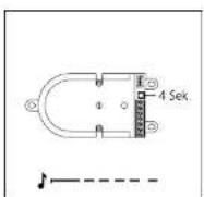
In the case of door, coudspeaker module 8TUM 650-... the programming mode is activated using the light button. Hold down the light button for 4 seconds until a protracted signal tone is audible.
In the case of the BTLE 050.... the programming mode is activated using the programming button. Next to the terminal, hold down the programming button for 1 seconds until a protracted signal tone is audible.

3 Siedle Classic
CLV xx 8-02 is set to the programming mode by actuating the programming button behind the front panel. Hold down the light button for 4 seconds until a protracted signal tone is audible.

4 Siedle Steel
The programming button is only accessible with the control panel
Activating the indoor devices
Depending on the type of bus indoor device, the programming mode has to be activated in a different way.

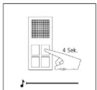
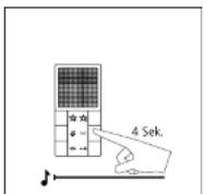
1 Siedle Basic Hold down the speech button for 4 seconds. A protracted acknowledgement tone sounds as confirmation and the muting LED begins to flash. The bus indoor device establishes the speed connection to the door station. The bus indoor device is now in the programming mode.

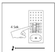
2 Bus telephone Lift the receiver at the bus telephone which you wish to program. Hold down the light button for 4 seconds. A protracted acknowledgement tone is audible in the receiver as confirmation. The bus telephone is now in the programming mode. Do not replace the receiver until after programming has been completed at the bus telephone.
3 Bus handsfree telephone Hold down the light button for 4 seconds. A protracted acknowledgement tone sounds as confirmation and the muting button begins to flash. The bus handsfree telephone establishes the speech connection to the door station. The bus handsfree telephone is now in the programming mode.
7.1 Programming – manual
Activating Jung indoor devices
1 Activate the standard audio indoor station
Hold down the light button for 4 seconds. A protracted acknowledgement tone sounds as confirmation and the muting button begins to flash. The standard audio indoor station establishes the speech connection to the door station.
The standard audio indoor station is now in the programming mode.
2 Activate the audio indoor station
Hold down the light button for 4 seconds. A protracted acknowledgement tone sounds as confirmation and the muting button begins to flash. The audio indoor station establishes the speech connection to the door station.
The audio indoor station is now in the programming mode.
Door call to Siedle Basic

1 Switch on the programming mode At the BNG/BVNG 650..., press the programming mode button briefly The LED 1 flashes in a 2-second rhythm to indicate that the programming mode is active.

- At the door station, hold down the light/programming button for 4 seconds. A protracted acknowledgement tone is then audible which is repeated every 5 seconds as long as the programming mode remains active.
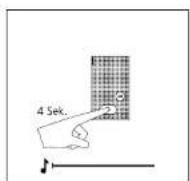
3 Hold down the speech button for 4 seconds. A protracted acknowledgement tone sounds as confirmation and the muting LED begins to flash. The bus indoor device establishes the speech connection to the door station. The bus indoor device is now in the programming mode.
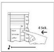
4 At the door station, hold down the required call button for 4 seconds until a projected tone sounds at the

5 The call button is now firmly assigned to the hands/re-bus phone
7.1 Programming – manual
Door call to bus telephone
At the bus telephone, a different
ring tone optionally be selected. The volume of the size will be
The volume of the door can ca changed at the bus telephones.

1 Switch on the programming mode. At the BNG/BVNG 650-..., press the programming mode button briefly. The LED 1 flashes in a 2-second rhythm to indicate that the programming mode is active.

2 At the door station, hold down the light/programming button for 4 seconds. A protracted acknowledgement tone is then audible which is repeated every 5 seconds as long as the programming mode remains active.
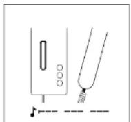
3 Lift the receiver at the bus telephone which you wish to program.

4 Hold down the light button for 4 seconds. A protracted acknowledgement tone sounds in the

5 At the door station, hold down the required call button for 4 seconds until a protracted tone sounds at the
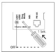
6 The call button is now firmly assigned to the hands-free bus telephone.
Door call to bus handsfree telephone
At the bus hands-free telephone a different ring tone can optionally be selected for the door call.
The volume of the door call can be changed at the bus handsfree telephone.

1 Switch on the programming mode At the BNG/BVNG 650..., press the programming mode button briefly The LED 1 flashes in a 2-second rhythm to indicate that the programming mode is active.

2 At the door station, hold down the light/programming button for 4 seconds. A protracted acknowledgement tone is then audible which is repeated every 5 seconds as long as the programming mode remains active.

3 Hold down the light button for 4 seconds. A prolonged acknowledgement tone is audible in the receiver, the muting button flashes. A speech connection exists to the door station. The bus telephone is now in the programming mode.

4 At the door station, hold down the required call button for 4 seconds until a projected tone sounds at the

5 The call button is now firmly assigned to the hands/re-bus tele-phone.
7.1 Programming – manual
Door call via the storey call button
Programming is only possible when the storey call button (ERT) is connected to the bus indoor device.
If there is no access available to an apartment, programming can still be carried out in this way.
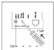
1 Switch on the programming mode. At the BNG/BVNG 650..., press the programming mode button briefly. The LED 1 flashes in a 2-second rhythm to indicate that the programming mode is active.
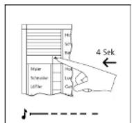
2 At the door station, hold down the light/programming button for 4 seconds. A protracted acknowledgement tone is then audible which is repeated every 5 seconds as long as the programming mode remains active.

3 Hold down the storey call button connected to the bus indoor device for 4 seconds. The bus indoor device is now in the programming mode. During this period, no ringing is admissible within the system.

4 At the door station, hold down the required call button for 4 seconds until a protracted tone sounds at the
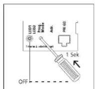
5 The call button is now firmly assigned to the bus indoor devices. Program additional users using the
Parallel door call
Where a door call has to be signalled at several bus telephones simultaneously.
Using the manual programming method, 2 bus indoor devices can be programmed in parallel.
For more information, see page 82
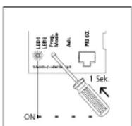
1 Switch on the programming mode. At the BNG/BVNG 650-... press the programming mode button briefly. The LED 1 flashes in a 2-second rhythm to indicate that the programming mode is active.

2 At the door station, hold down the light/programming button for 4 seconds. A protracted acknowledgement tone is then audible which is repeated every 5 seconds as long as the programming mode remains active.
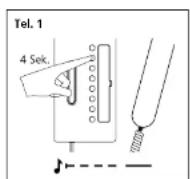
3 Lift the receiver at the bus telephone which you wish to program. Hold down the light button for 4 seconds. A protracted signal tone is audible in the receiver. A speech connection exists to the door station. The bus telephone is now in the programming mode. Do not replace the receiver!

4 Lift the receiver at the second bus telephone which you wish to program. Hold down the light button
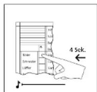
5 At the door station, hold down the required call button for 4 seconds until a protracted tone sounds at the

6 Replace the receiver at all bus telephones which have been programmed. The call button is now
7.1 Programming – manual internal call
You wish a bus telephone to be able to call and communicate with another bus telephone in the system.
The muting and light buttons of the
bus telephone can be reprogrammed if required for internal call functions. With the deluxe bus telephone up to 7 other bus telephones can be called.

1 Switch on the programming mode. At the BNG/BVNG 650..., press the programming mode button briefly. The LED 1 flashes in a 2-second rhythm to indicate that the programming mode is active.

2 Lift the receiver at the first bus telephone you wish to enable for internal calls. The programming mode tone is audible.
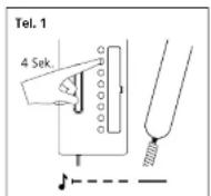
3 Hold the light button down for 4 seconds. The acknowledgement tone is audible. Do not replace the receiver.
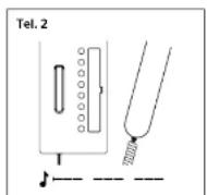
4 Lift the receiver at the second bus telephone you wish to enable for internal calls. The programming

5 Held the light button down for 4 seconds. The acknowledgement tone is audible. Do not replace the

6 A speech connection now exists between the two bus telephones.

7 At the first bus telephone, hold down the internal call button you wish to use to call the second bus telephone for 4 seconds. A protracted tone is audible. The bus telephone is now programmed. Do not yet replace the receiver.
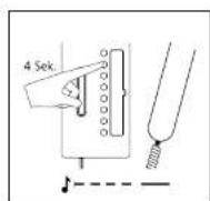
8 At the second bus telephone, hold down the internal call button you wish to use to call the first bus telephone for 4 seconds.
A protracted tone is audible.
The buttons are now programmed at both bus telephones.
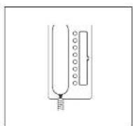
9 Replace the receiver at both bus telephones. Program additional bus telephones using the same procedure or quit the programming mode.
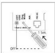
10 Switch of the programming mode at the BNG/BVNG 650...
7.1 Programming – manual Dialling the door station
You wish to be able to call one or more door stations from a bus telephone using buttons, e.g. in order to selectively speak to a visitor.
This function can be programmed for any bus telephone to any button. The only exception is the door release button.

1 Switch on the programming mode. At the BNG/BVNG 650-... press the programming mode button briefly. The LED 1 flashes in a 2-second rhythm to indicate that the programming mode is active.
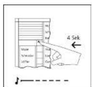
2 At the door station, hold down the light/programming button for 4 seconds. A protracted acknowledgement tone is then audible which is repeated every 5 seconds as long as the programming mode remains active.

3 Lift the receiver at the bus telephone which you wish to program.
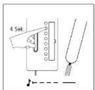
4 Hold down the light button for 4 seconds. A contracted acknowledgement tone sounds in the
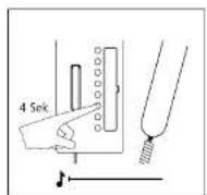
5 At the bus telephones, hold down the button you wish to use to call the door station for 4 seconds.
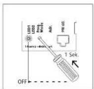
6 Replace the receiver. Continue to program more bus telephones or quit the programming node
Call differentiation of 2 door stations
At the bus telephone you wish to be able to tell at which door the door call has been made, e.g. whether a door call has come from the main entrance or a side entrance.
Call differentiation can take place from max. 2 doors. Door call 1 = Tone sequence 1 Door call 2 = Tone sequence 2

1 Switch on the programming mode At the BNG/BVNG 650..., press the programming mode button briefly The LED 1 flashes in a 2-second rhythm to indicate that the program- ming mode is active.
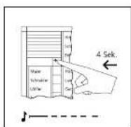
2 At the door station, hold down the light/programming button for 4 seconds. A protracted acknowledgement tone is then audible which is repeated every 5 seconds as long as the programming mode remains active.
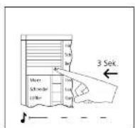
3 Hold down the light/programming button again for 3 seconds. A short acknowledgement tone is audible. At the bus telephones, a different tone sequence is audible when a call is placed by this door station.

4 Switch off the programming mode at the RNG/PVNG 650...
7.1 Programming – manual
Additional contact on the BSM 650-...
In addition to an already programmed bus telephone, you wish a potential-free switching contact to be closed when a door call is placed.
Actuation of an additional bell or lamp on placement of a door call.
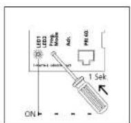
1 Switch on the programming mode. At the BNG/BVNG 650-... press the programming mode button briefly. The LED 1 flashes in a 2-second rhythm to indicate that the programming mode is active.

2 Switch the BSM 650- to the programming mode. To do this, briefly press the programming mode button using a small screwdriver. LED 1 lights up and flashes slowly after appr. 3 seconds.
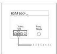
3 Select the relevant relay by actuating the Prog. mode button at the BSM 650-... with a screwdriver until the required LED lights up (LED2 = relay2, press 2x).
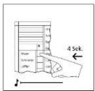
4 Press the button to which you wish the relay to be assigned and hold down for 4 seconds.

5 The switching time for the contact is determined by the time for which the screwdriver is held down.
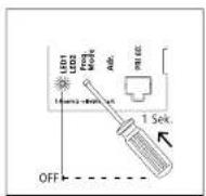
6 Continue to program more control buttons or quit the programming mode.
Button of a bus telephone on the BSM 650-...
Actuation of a contact in the
8SM 650-..., e.g. in order to open a garage or switch on a staircase light.
Using the bus programming soft-
ware BPS 650-... the switching function/time can now be changed.

1 Switch on the programming mode. At the BNG/BVNG 650-..., press the programming mode button briefly. The LED 1 flashes in a 2-second rhythm to indicate that the programming mode is active.
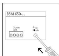
2. Switch the BSM 650... to the programming mode. To do this, briefly press the programming mode button using a small screwdriver.
LED 1 lights up and flashes slowly after acpr. 3 seconds.

3 Select the relevant relay by actuating the programming mode button at the BSM 650-... with the screwdriver until the required LED lights up (LED 1=relay 1).

4 Lift the receiver at the bus telephone at which you wish to program a button. Press the button you

5 The switching time for the tortact is determined by the time for which the screwdriver is held down.

6 Continue to program more control buttons or quit the programming mode.
7.1 Programming – manual
Call button of a door station on the BSE 650-...
Potential-free switching contact which is closed on placement of a door call. Actuation of e.g. a battery-operated chime or additional bell on placement of a door call.
Due to the structure design, the BSE 650-... can be mounted in a 55 junction box. The bus telephone must already be programmed to the call button.
If the BSE 650- is not actuated in parallel with a bus telephone, before pressing the call button the door loudspeaker must be set to the programming mode.

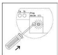
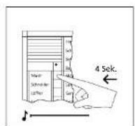
1 Switch on the programming mode At the BNG/BVNG 650..., press the programming mode button briefly. The LED 1 flashes in a 2-second rhythm to indicate that the program- ming mode is active.
2 Switch the BSE 650-... to the programming mode. To do this, briefly press the programming mode button with a small screwdriver. The LED flashes slowly:
3 At the door station, press the call button you wish to be assigned to the BSE 650-... An assignment to one or more bus telephones must exist.

4 Program additional users using the same procedure or that the programming mode
Button of a bus telephone on the BSE 650-...
Actuation of additional functions such as switching on the staircase light or garage door OPEN/SHUT. Switching time with manual programming 1 second.
Using the bus programming software BPS 650-... the switching function/time can now be changed.


1 Switch on the programming mode At the BNG/BVNG 650..., press the programming mode button briefly The LED 1 flashes in a 2-second rhythm to indicate that the program- ming mode is active.
2 Switch the BSE 650- to the programming mode. To do this, briefly press the programming mode button with a small screwdriver. The LED flashes slowly.
3 Lift the receiver at the bus telephone at which you wish to program a button.
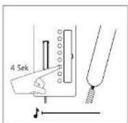
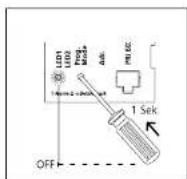
4 Press the button you wish to pro- gram and hold down for 4 seconds. A pre-rated acknowledgement tone
5 Program additional uses using the same procedure or quit the programming mode.
7.1 Programming – manual
Bus secondary signal unit BNS 750-...
Signal device to additionally indicate
the door call and/or storey call in another room.
Where there are several doors, the same programming sequence must
be used every time.
For activating an indoor device
(switching to the programming mode)
For more information, see
page 53

1 Switch on the programming mode. At the BNG/BVNG 650-..., press the programming mode button briefly. The LED 1 flashes in a 2-second rhythm to indicate that the programming mode is active.

- At the door station, hold down the light/programming button for 4 seconds. A protracted acknowledgement tone is then audible which is repeated every 5 seconds as long as the programming mode remains active.

3 Hold down the light button for 4 seconds. A protracted acknowledgement tone sounds in the receiver, the muting button flashes A speech connection exists to the door station. The bus telephone is now in the programming mode. Leave the receiver off the hook.
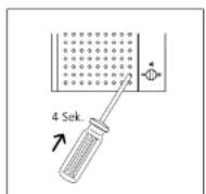
4 Hold down the programming button of the bus secondary signal unit through the opening in
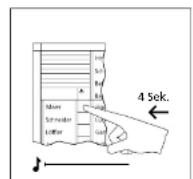
5 At the door station, hold down the required call button for 4 seconds until a protracted tone sounds at the

6 Replace the receiver. Continue to program more bus telephones or quit the programming mode.
Call via DRM 612-...
Bus telephones are called from the door station via the display call module DRM 612-... The names in the display call module DRM 612-... must be assigned
already prior to the start of user programming. Names are entered at a PC using the programming software PRS 602-... For connection of the PC to the DRM 612-... the
programming interface PRI 602-... is required.

1 Switch on the programming mode. At the BNG/BVNG 650-... press the programming mode button briefly. The LED 1 flashes in a 2-second rhythm to indicate that the programming mode is active.
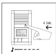
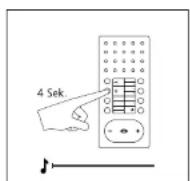
- At the door station, hold down the light/programming button for 4 seconds. A protracted acknowledgement tone is then audible which is repeated every 5 seconds as long as the programming mode remains active.
3 Hold down the light button for 4 seconds. A prolonged acknowledgement tone is audible in the receiver, the muting button flashes. A speech connection exists to the door station. The bus telephone is now in the programming mode.
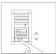
4 At the door station, select the required name using the two arrow buttons.
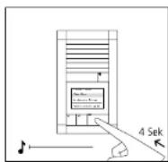

5 When the selected name is shown in the display, hold down the OK button on the DRM 612.... for
6 Program additional users using the same procedure or quit the programming mode.
7.1 Programming – manual Door call to Jung indoor station
At the Jung indoor station, a different ring tone can optionally be selected for the door call.
The volume of the door call can be changed at the Jung indoor device.

1 Switch on the programming mode. At the BNG/BVNG 650..., press the programming mode button briefly. The LED 1 flashes in a 2-second rhythm to indicate that the programming mode is active.

2 At the door station, hold down the light/programming button for 4 seconds. A protracted acknowledgement tone is then audible which is repeated every 5 seconds as long as the programming mode remains active.

3 Hold down the light button for 4 seconds. A protracted acknowledgement tone sounds as confirmation and the muting button begins to fash. The audio indoor station establishes the speech connection to the door station. The audio indoor station is now in the programming mode.
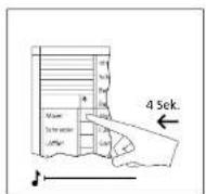
4 A: the door station, hold down the required call button for 4 seconds until a pretracted tone sounds at the

5 The call button is now firmly assigned to the audio indoor station.
Parallel door call to Jung indoor station
A door call has to be signalled at several Jung indoor stations simultaneously.
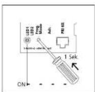
1 Switch on the programming mode At the BNG/BVNG 650..., press the programming mode button briefly The LED 1 flashes in a 2-second rhythm to indicate that the program- ming mode is active.
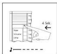
2 At the door station, hold down the light/programming button for 4 seconds. A protracted acknowledgement tone is then audible which is repeated every 5 seconds as long as the programming mode remains active.

3 Audio indoor station 1: Hold down the light button for 4 seconds. A protracted acknowledgement tone sounds as confirmation and the muting button begins to flash. The audio indoor station establishes the speech connection to the door station. The audio indoor station is now in the programming mode.

4 Audio indoor station 2: Hold down the light button for 4 seconds. A pro-raced airway

5 At the door station, hold down the required call button for 4 seconds until a protracted tone sources at the
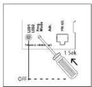
6 The call button is now fully assigned to the audio indoor station.
7.1 Programming – manual
Internal call between Jung indoor stations
You wish a Jung indoor station to be
able to call and communicate with
another Jung Indoor station in the system.

1 Switch on the programming mode.
At the BNG/BVNG 650-..., press the
The LED 1 flashes in a 2-second
rhythm to indicate that the programming mode is active.
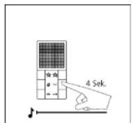
2 Audio indoor station 1:
Hold down the light button for
4 seconds. A protracted acknowledgment tone sounds as confirmation and the muting button begins to flash.

3 Audio indoor station 2:
Hold down the light button for
4 seconds. A protracted acknowledgment tape sounds as copisma
edgement: bone sounds as confirmation and the muting button begins to flash.

4 A speech connection now exists
between the two audio indoor stations.
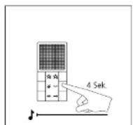
5 Audio indoor station 1:
Hold down the internal call button you wish to use to call the second

6 Audio indoor station 2:
Hold down the internal call button you wish to use to call the first
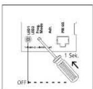
7 Switch off the programming mode at the 8NG/BVNG 650-
7.2 Programming – Plug+Play Basics
Plug+Play programming offers the opportunity for those without programming experience to commission an In-Home bus system. The entire installation of all users must have been completed. The housings of the bus telephones must not yet have been closed. The Plug+Play mode must be activated at the bus line rectifier. By being connected to the bus door loudspeaker, the call buttons at the bus call button module are assigned a constructive number. The bus telephones are subsequently locked onto the base plates in this sequence.
Conditions for Plug+Play: - Plug+play-programming is only possible with new bus indoor devices, new bus door loudspeaker B1JM 650-0491LE 050-03, bus call button modules BIM 650-041, -02, -03, -04, BIMA 050-01 and bus line rectifiers ENQ/BVNG 650-... - Plug+play-programming only works for bus indoor devices within any one line. - Several door stations within a line are programmed simultaneously with the same assignment, e.g. two door stations with 4 call buttons have the same assignment. Where there is more than one bus call button module, numbering of the call buttons takes place in the same sequence in which the modules are connected to each other via the INOUT connections.
Conditions for Plug+Play: - Install the system in accordance with the wiring diagram. - Connect the base plates of the bus telephones, do not yet close the housings. - With Smart Gateway MiniSiedle Scope, do not yet connect the base station to the In-Home bus. - Connect the lung modules to each other using the supplied connecting cables. The terminal block must not yet be plugged in. - At the door station, document the assignment of call buttons or if possible inscribe straight away. - Set the bus line rectifier to the Plug+Play mode by holding down the programming mode button for 5 seconds. LED 1 must stay on continuously. - Mount the bus telephones on the base plates in the same sequence as the assignment of call buttons. (receiver down) - With Smart Gateway MiniSiedle Scope, connect the base station to the In-Home bus. - Where a Jung indoor station is used, plug in the terminal block. - The rotary call is audible briefly after appr. 7 seconds as an acknowledgement and the LED under the call silencing button starts to flash. The next bus telephone can then be closed. - After all the telephones have been closed, at the bus line rectifier press the programming mode button. The programming mode is switched off, the programming of the system is complete.
Reset Plug=Play: All already connected bus telephones must be locked into position on the base plates. • Switch off the supply voltage to the bus line rectifier. • Disconnect terminals ta and lb • Change the address of the bus line rectifier, e.g. from address 1 to address 2 • Hold down the Prog. mode button for around 3 seconds and switch on the supply voltage of the bus line rectifier. After around 3 seconds, release the button, wait until LED 1 indicates the standard operating mode again. • Reconnect terminals To and To and wait until the system has finished running up. • Pick up all bus telephones from the base plates again. • Return the address switch to its original status, e.g. change from 2 to 1, and wait until the system has finished running up. Check whether all the bus telephones have been picked up again. Plug Play programming can begin again.

text_image
SSS SIEBLE 12 4 3 2 1Bus custom-fit door loudspeaker
The sequence of terminals on the bus call button matrix corresponds to the sequence of bus telephones.
Terminal 7.1 = Bus telephone ↑
Terminal 7.12 - Bus telephone 12
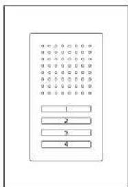
text_image
Diagram of a rectangular device with four labeled buttons arranged in rows and columnsSiedle Classic
The sequence of terminals on the bus call button matrix corresponds to the sequence of bus telephones. The uppermost button is button 1, remaining buttons follow in consecutive sequence.
Terminal 7.1 = Bus telephone 1
E.
Terminal 7.4 = Bus telephone 4
Assignment of bell buttons:
BTN 650 01 BTN 650 02
TM 650-03 BTM 650-04
7.2 Programming – Plug+Play Example of a 4-family home
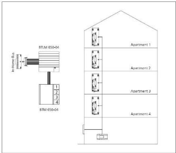
text_image
BTLM 650-04 In-Home Bus in- BTM 650-04 1 2 3 4 Apartment 1 Apartment 2 Apartment 3 Apartment 4Restrictions
- Bus telephones which are already assigned to a door loudspeaker in the same line are not reprogrammed.
- Bus telephones which are already programmed in a different line are reassigned to a bell button.
- Call buttons of the BTI-MBTIF are disabled during Plug-Play programming, no inputs can be made.
- Plug+Play programming can be continued in an existing web. The
Possible errors
- If unsuitable devices log in during Plug+Play programming (old bus telephone models such as BTS/ BTC 750-... or BSM etc.) the con-
figuration is aborted and an error signal sent to fault LED 2 at the ENG/BVNG 650...
• I door bell buttons have been assigned to the wrong bus telephones during Plum-Play app.
gramming, the RNG/BVNG 650- must be returned to an allocated
Procedure – Example

text_image
OFF LED Driver LED Resistor Ado 5 Ssk ON1 Activate the Plug-Play-mode at the BNG/BVNG 650..., hold down the programming mode button for 5 seconds. LED 1 lights up permanently.

text_image
A-1 A-2 A-3 A-42 Set up the bus telephone in apartment 1 with the receiver in place, the storey call sounds as an acknowledgement tore and the LED of the muting button flashes. Bus telephone 1 is assigned to button 1.
text_image
Apartment 1 Apartment 2 Apartment 3 Apartment 43 Set up the bus telephone in apartment 2 with the receiver in place, the storey call sounds as an acknowledgement tone and the LED of the muting button flashes.

text_image
A2014-1 A2014-2 A2014-3 A2014-4
text_image
Appl 11.06.1 Appl 11.06.2 Appl 11.06.3 Appl 11.06.4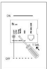
text_image
ON LED LED2 Power AIR LED US OFF 1 Sek7.3 Programming – with PC BPS 650-... and PRI 602-... USB
Using bus programming software BPS 650... the entire function of an In-Home system can be programmed using a Windows PC. For connection of the PC to the in-Home installation, the programming interface PRI 650... USB and the bus power supply accessory ZBVG 650... are required. The ZBVG 650... is plugged once within a system and once in a BNGBV8NG 650... The PRI 650... USB can be permanently installed in a system or can be plugged in via an B-pin Western junction box. Current updates for the BPS 650... software are available in the downloaded area under www.siedle.com. For more information on how to commission the system using the Bus programming software BPS 650... refer to the software online help.
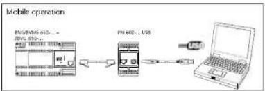
flowchart
graph LR
    A["Device 1"] --> B["Mobile Device"]
    B --> C["USB"]
    C --> D["Laptop"]
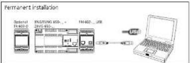
text_image
Permanent installation Optional F402-3 ENGWING SSD...+ ENW 915 F402-3...USB USB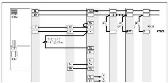
flowchart
graph TD
    A["BTM"] --> B["To"]
    A --> C["Tb"]
    B --> D["b"]
    B --> E["c"]
    C --> F["bv"]
    C --> G["c"]
    D --> H["To"]
    D --> I["b"]
    E --> J["c"]
    F --> K["To"]
    F --> L["b"]
    G --> M["c"]
    H --> N["LT"]
    I --> O["LT"]
    J --> P["LT"]
    K --> Q["LT"]
    L --> R["LT"]
    M --> S["LT"]
    N --> T["XT"]
    O --> U["ERT"]
    P --> V["E"]
    Q --> W["RTERT"]
    R --> X["RTERT"]
    S --> Y["RTERT"]
    T --> Z["RTERT"]
    U --> AA["RTERT"]
    V --> AB["RTERT"]
8 Supplementary functions
Switching and control functions
Bus switching unit Bus switching module Bus input module

Application
1 Changeover contact, e.g. for
- Switching the outside light
- Opening the garage door
- Staircase lighting
- Mounting possible in a 55/70
junction box
- Switching functions possible with
feedback to deluxe bus indoor devices
- 230 V AC consumers can be
switched directly
Application
4 working contacts, e.g. for
- Switching the outside light
- Opening the garage door
- Staircase lighting etc
- Mounting on top hat rail
Application
Optical feedback of switching
statuses, e.g.
- Open garage door,
- Error message heating
- To actuate the BSE/BSM 650-
- Mounting possible in a 55/70 junc-
tion box
Function
- Switch ON/OFF
• Timer between 0.4 seconds and
19 minutes 59 seconds(as-delivered
status)
- Toggle function (status change with
each button actuation;
• Secondary signal contact for
additional bel
• Supply via In-Home bus
Function
• Timer between 0.4 and 12 seconds
switching of an additional door
release or gate
• Secondary signal contact for addi-
tional bell
Function
- Initiation of switching/control func-
tions within the Siedle In-Home bus
• Signal input within the Siecle
In-Home bus
• Supply via In-Home bus.
Actuation via
• Control buttons of the bus tele-
phones
• Light or call button of a door station
• Bus input module BEM 650-...
Actuation via
• Control buttons of the bus tele-
phones
• Light or call button of a door station
- Bus input module BEM 650-
Actuation via
Potential-free button or Direct voltage
4-30VDC
[Non-Text]
[Non-Text]
Programming
Manual programming services
Programming
E. Incentive set only in a nonparamidal
8 Supplementary functions Door release actuation
In deviation from the standard plans, the door release can be actuated in various ways. The bus line rectifier BNG8VNG 650-... has a DR contact which is closed every time the door release button is actuated. At the door loudspeakers BILM 650-... and BTLL 050-... there is also a door release contact which is only closed when the bell has previously been rung at the relevant door loudspeaker. If several door loudspeakers
are operated within a system, both contacts are required to open the door station. In general, high-resistance door releases must be used in order to guarantee the greatest possible degree of operating reliability/ the greatest possible range. Use a Siedle door release or a 12 V AC door release with an impedance of at least 20 Chm.
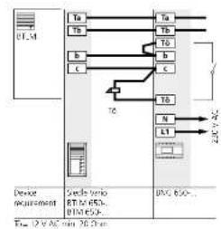
flowchart
graph TD
    A["Device requirement"] --> B["TA"]
    A --> C["Tb"]
    A --> D["b"]
    A --> E["c"]
    B --> F["TA"]
    B --> G["Tb"]
    B --> H["b"]
    B --> I["c"]
    C --> J["Tb"]
    C --> K["N"]
    C --> L["L1"]
    D --> M["20V AC"]
    E --> M
    F --> N["20V AC"]
    G --> N
    H --> N
    I --> N
    J --> N
    K --> N
    L --> N
    M --> N
    N --> O["DC 650..."]
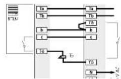
Application
Externally positioned door stations The door release contact (DR contact) at the bus line rectifier switch every time the door release button is pressed.
- Lamper-proof, no access from the outside
- Only 4 cores to the door station
Drawbacks
• The door release must be routed to
the distribu - installation only possible with
- With several door stations, this installation is not possible
Application
Externally positioned door stations The bus line rectifier OR contact and the OR contact in the door loudspeaker are used. Both contacts switch every time the door release button is pressed.
Benefits
• Temper-proxel, as no access from the outside
- Tampier-proof door release even with several door stations in a router.

flowchart
graph TD
    A["Device regenerator"] -->|Ta/Tb| B["Stock var diode"]
    B -->|Ta/Tb| C["Stock var diode"]
    C -->|Ta/Tb| D["BNS GSD..."]
    A -->|Tb| E["BT/AC"]
    B -->|Tc/Td| F["BT/AC"]
    C -->|Td/Te| G["BT/AC"]
    D --> H["BT/AC"]
    style A fill:#f9f,stroke:#333
    style B fill:#ccf,stroke:#333
    style C fill:#ccf,stroke:#333
    style D fill:#ccf,stroke:#333
    style E fill:#dfd,stroke:#333
    style F fill:#dfd,stroke:#333
    style G fill:#dfd,stroke:#333
    style H fill:#dfd,stroke:#333
Application
Systems with more than one door
station with door release.
The To contact (door release con-
fact, in the bus line rectifier and the
door release contact in the door loudspeaker are used. The renta
in the ANG/BVNG 650-... switches
the door release button every time
it is pressed, the contact in the door
loudspeaker only at the door from
which the last door call was placed.
Benefits
• Target proof, as no access from
the curbs
Drawbacks
• The door release must be routed to
the distribu
- 5 cores are required to each door
STROCH
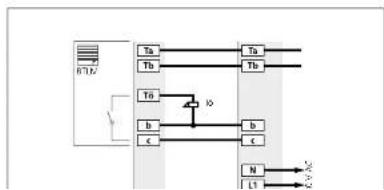
flowchart
graph TD
    A["Input"] --> B["Ta"]
    A --> C["Tb"]
    A --> D["Tn"]
    B --> E["Output"]
    C --> F["Output"]
    D --> G["Output"]
    H["Inverter"] --> I["Switch"]
    I --> J["IO"]
    J --> K["b"]
    J --> L["c"]
    K --> M["N"]
    L --> M
    M --> N["L1"]
    N --> O["AC"]
Application
Garden gate or areas without secu-
nity relevance
The DII contact in the door loud-
speaker switches every time the door
RELEASE BUTTON E pressed
Benefits
- Only 4 cores to the door station.
the door release is connected directly
in the door station
• Several door stations possible
without additional installation
Barnish, also
8 Supplementary functions
Parallel door call
Manual programming
In general, Z telephones can be switched in parallel. Parallel operation can be extended when programming manually to include the deluxe bus telechones BTC/BFC 850-... and auxiliary circuit board ZPS/ZPSF 850-...
Programming with PC and BPS
During PC programming, 4 A/B 150-... BTS/BTC/BFC 850-... units can be programmed in parallel without a supplementary power supply. From the 5th bus telephone, BTC/BFC 850-... units with sup- plementary power supply via ZPS/ ZPSF 850-... are essential.
In case of manual programming
only 2 bus telephones can be programmed in parallel without ZPS 850-... When programming using BPS 650-... 4 bus telephones can be programmed in parallel without ZPS/ZPSF 850-... For more information, see page 83
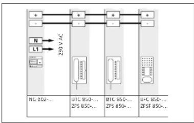
flowchart
graph TD
    A["+"] --> B["220V AC"]
    C["-"] --> B
    D["N"] --> B
    E["L1"] --> B
    B --> F["+"]
    B --> G["-"]
    H["NG 802-..."] --> I["220V AC"]
    J["BTC 850-..."] --> K["ZPS 850-..."]
    L["BTC 850-..."] --> M["ZPS 850-..."]
    N["BFC 850-..."] --> O["ZFSF 850-..."]
A maximum of 3 ZPS/ZPSI 850... units can be supplied by a line rectifier NG 602... The maximum current of the 73.3 V DC direct voltage of the NG 602... is 300 mA. The specified ranges only apply to the external power supply in the devices, not to the range of the In-Home bus. Ranges applicable for J-YIST/Y or YR installation cable with 0.8 mm core diameter! Only bus telephones with ZPS/ ZPSF 850... located in the same line can be supplied by one line rectifier. Combined operation of BIC 850... and BIC 850... is possible.
Current consumption and ranges
with supplementary power
supply
voltage range: 20-30 V DC
Power supply with NG 602-... Max. conductor length/Distance of the supplementary supply
| 8TC 850-... with ZPS 850-...Current consumption 100 mA | 1st device260 m | 2nd device130 m | 3rd device80 m | 4th devicenot possible |
| 8FC 850-... with ZPSF 850-...Current consumption 100 mA | 1st device260 m | 2nd device130 m | 3rd device80 m | 4th devicenot possible |

flowchart
graph LR
    A["M"] --> B["20kV AC"]
    C["N"] --> B
    D["LT"] --> B
    B --> E["50kV DC"]
    E --> F["DC 50kV DC"]
    E --> G["DC 50kV DC"]
    E --> H["DC 50kV DC"]
    E --> I["DC 50kV DC"]
A maximum of 8 ZPS/ZPSF 850-...
units can be supplied by a video line positif or NC 603. The maximum
current of the 30 V DC direct voltage
from the VNG 602-... is 1100 mA.
The specified ranges only apply to
the external power supply to the devices, not to the range of the
In-Home bus. Ranges applicable for
J-Y(ST)Y or YR installation cable with
0.8 mm core diameter!
Only bus telephones with ZPS/
ZPSF a50... located in the same
line certifies. Continued operation
of BTC 850- and BEC 850- is
possible.
Power supply with VNG 602-... Max. conductor length/Distance of the supplementary supply
| BTC 850-... with ZPS 850-...Current consumption 100 mA | 1-4th devices300 m | 5th device250 m | 6th device200 m | 8th device130 m |
| BFC 850-... with ZPSF 850-...Current consumption 100 mA | 1-4th devices300 m | 5th device250 m | 6th device200 m | 8th device130 m |
8 Supplementary functions Parallel door call
Parallel programming of several bus telephones to one call button. - On principle, all combinations can be programmed with BPS 650-...
- Manual programming with 8 BTC/8FC 850-... units is possible if from the 3rd bus telephone each BTC 850-... uses a ZPS 850-... /each 8FC 850-... uses a ZPSF 850-...
- BTS 850-... and A/B 150-... can only be programmed as 1-4 bus telephones - Programming must start at the bus telephones which do not have any additional power supply connected.
| Manual prog. | Prog.with BPS 650- | Bus-telephones 1-2 | Bus-telephones 3-4 | Bus-telephones 5-8 | |
| X | X |  | |||
| X | X | ||||
| X | X | ||||
| X |  |  | |||
| X | |||||
| X | X |  |  | ||
| X | X | ||||
| X |  |  | 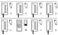 | ||
| X | X | ||||
Supply of Jung audio indoor
stations
A maximum of 15 Jung audio indoor stations can be supplied by a VNG 602-... line rectifier. The maximum current of the 30 V DC direct voltage from the VNG 602-... is 1100 mA. The specified ranges only
apply to the external power supply of the devices, not to the ranges of the In-Home bus. Ranges applicable for J-YISTY or YR installation cable with 0.8 mm core diameter! Only devices which are located in the same line can be supplied by one line rectifier.
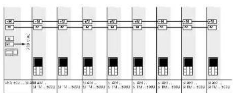
flowchart
graph TD
    A["Module A"] --> B["Pin 1"]
    A --> C["Pin 2"]
    B --> D["Module B"]
    C --> E["Module C"]
    D --> F["Pin 3"]
    E --> G["Pin 4"]
    F --> H["Module D"]
    G --> I["Module E"]
    H --> J["Pin 5"]
    I --> K["Pin 6"]
    J --> L["Module F"]
    K --> M["Module G"]
    L --> N["Pin 7"]
    M --> O["Pin 8"]
    N --> P["Module H"]
    O --> Q["Module I"]
    P --> R["Pin 9"]
    Q --> S["Pin 10"]
Power supply with NG 602-... Max. conductor length/Distance of the supply
| SI AM ... | 1 device | 2 device | 3 B device |
| SI TM ... 5093 | 90 m | 50 m | Further additional power supply |
| Current consumption 75 mA | |||
Power supply with VNG 602-... Max. conductor length/Distance of the supply
| SI AM | 1-3th devices | 4 device | 5 device | 6 device | 7 device | 8 device | 15 device |
| SI TM, 5093 | 300 m | 250 m | 200 m | 180 m | 150 m | 130 m | 50 m |
| Current consumption 75 mA | |||||||
8 Supplementary functions Storey call parallel switching
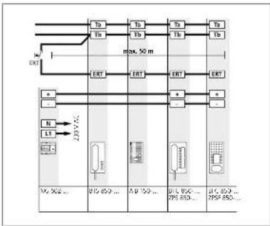
flowchart
graph TD
    A["Ta"] --> B["TA"]
    C["Tb"] --> D["Tb"]
    E["Ta"] --> F["Tb"]
    G["Ta"] --> H["Tb"]
    I["EXT"] --> J["max. 50 m"]
    K["ERT"] --> L["ERT"]
    M["ERT"] --> N["ERT"]
    O["a"] --> P["a"]
    Q["-"] --> R["-"]
    S["N"] --> T["N1"]
    U["L1"] --> V["L2"]
    W["I2P 450"] --> X["12P 450..."]
    Y["12P 100..."] --> Z["12P 100..."]
    AA["12P 650..."] --> AB["37P 650..."]
    AC["37P 850..."] --> AD["27P 850..."]
Storey call parallel switching
The storey call button, ERT is used to call into the apartment from an apartment door. To call several bus telephones, the ERT terminal can be connected in parallel, e.g. office floor with 4 bus telephones with one storey call button at the storey entrance.
A maximum of 8 bus telephones can be rung in parallel using a storey call button.
- If the bus telephones are additionally supplied via parallel watching accessory 7PS 850..., then all the bus telephones ring simultaneously.
- If the bus telephones have no additional power supply, the storey call can be heard in sequence at the telephones.
The complete range of the storey call amounts to 50 m with an 0.8 mm core diameter.

flowchart
graph TD
    A["In Home Bus Audio"] --> B["Ta"]
    A --> C["Tb"]
    B --> D["TA"]
    C --> E["Tb"]
    F["875BTC 850..."] --> G["ERT"]
    H["ENS 750..."] --> I["ERT"]
Bus secondary signal unit
Additional bus secondary signal unit in parallel at a bus telephone. Signalling door calls and storry calls. Following the installation, the door tall must be programmed at both devices. For more information, see page 68
Supplementary contact, radio chime, pilfer safeguard
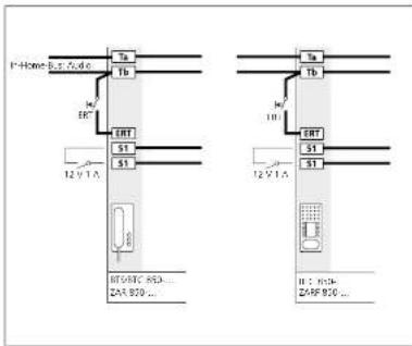
text_image
Home Bus, fuse Ta Tb M EHT ERT S1 S1 12 VTA BTV8TC 853... ZAR 920... 12 VTA Ta Tb M EHT S1 S1 H: 910- Z45F 916...Supplementary contact in the
bus indoor device
The bus indoor devices provide an additional contact at terminal
en additional contact 9. terminators S152
Actuation of an additional signaling device such as a radio chime or optical display of the door call. If the contact is required in the sub-distributor, the door call can be programmed to a contact at a BSE/BSM 65D...
As delivered status, secondary signal unit function 1 second, can be multifunctionally reprogrammed using BFS 650.
Using the BPS 650-, the contact can also be programmed to a button of the bus telephone, to switch it to potential-free status.
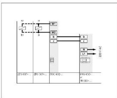
flowchart
graph TD
    A["Q1"] --> B["M1"]
    C["E1"] --> D["M2"]
    E["2P5 601-..."] --> F["2P7 501-..."]
    G["OSC 602-..."] --> H["BNS 60C-"]
    I["IR 603-..."] --> J["IR 604-..."]
    K["N"] --> L["L1"]
    M["220 VAC"] --> N["->"]
Pilfer safeguard for Vario mod-
ules
Biscable magnet for integration in mounting frame MR 611-
To secure valuable modules such as camera modules, code lock modules or to ensure tamper-proof operation of the door release.
A stable metal plate locks the opening mechanism and prevents modules from being removed. The magnets are opened and locked in the sub-distributor at pifer safeguard controller DSC 602.... A maximum of 2 ZD5 601.... units can be operated at one DSC 602....
Range
Maximum conductor length between OSC 602-... and ZDS 601-... with 0.8 mm con diameter 100 m.
8 Supplementary functions
Staircase light/Outside light
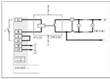
flowchart
graph TD
    A["Li"] --> B["12V AC"]
    C["b"] --> B
    D["c"] --> B
    E["N"] --> F["230V AC"]
    G["L"] --> F
    H["230V AC"] --> I["N"]
    J["230V AC"] --> K["L"]
Light actuation
The light button in the bus indoor devices or BTLM 650-... is used to actuate the light contact in the bus
atctuate the light contact in the bus lice rectif at BNG/BVNG 650-
following completion of the instal-
lation, this function is active without
any further programming.
To actuate the staircase and/or
outside light, according to VDE
regulations a light current relay or
Lima relay (e.g. 7
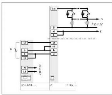
flowchart
graph TD
    A["230V AC"] --> B["25V AC"]
    B --> C["230V AC"]
    C --> D["25V AC"]
    D --> E["230V AC"]
    E --> F["25V AC"]
    F --> G["230V AC"]
    G --> H["25V AC"]
    H --> I["230V AC"]
    I --> J["25V AC"]
    J --> K["230V AC"]
    K --> L["25V AC"]
    L --> M["230V AC"]
    M --> N["25V AC"]
    N --> O["230V AC"]
    O --> P["25V AC"]
    P --> Q["230V AC"]
    Q --> R["25V AC"]
    R --> S["230V AC"]
    S --> T["25V AC"]
    T --> U["230V AC"]
    U --> V["25V AC"]
    V --> W["230V AC"]
    W --> X["25V AC"]
    X --> Y["230V AC"]
    Y --> Z["25V AC"]
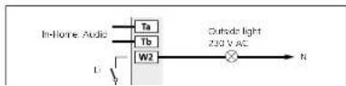
Light actuation
Actuation of an additional lamp
via BSE 650-... Max. contact load
230VAC,6A
9 Servicing
Restart, exchange, operating mode
Restarting the system
A restart of the complete system is
known as a Power-ON-Reset.
Switch off the power supply to the
bus line rectifier, wait for a few
seconds, switch the power back on.
The system restarts, and all bus users
are initialized again. The system pro-
gramming is retained.
Delete programming
• Disconnect terminals Ta and Tb
- Change the address of the bus line
rectifier, i.e. change the address from
1 to another address which is still
unassigned, e.g. 2. In multiple-line
systems, ensure that no address has
been assigned more than once, (no
waiting time required, as no device i
connected at the line:
• Connect bus cores Ta and Tb
- Connect bus cores to and to
Restoring the as-delivered status
All programmed users in the bus line
rectifier are deleted, the system mus
be subsequently reprogrammed
Procedure
• Switch off the supply voltage to
the bus line rectifier
• Disconnect terminals Ta and Th
• Held down the preparing
mexie button
- Switch on the voltage and release
- Switch on the voltage and release the programming mode button after
the program ans 5 raspa
- Function LED 1 flashor supply
• Function LED 1 flashes evenly • I/Visit until the LED 1 displays
- Wait until the LED I display returns to show the normal operating
to show the normal operating
• Change the address of the bus
line rectifier, e.g. set address 1 to 2.
in multiple-line systems, ensure that
no address has been assigned more
than once.
• Connected bus cores Ta and Tb
• The system is rainitialized
• Function LED 1 flashes ax
For example, the results of
Exchanging bus telephones in an
existing system
If an already programmed bus
telephone has to be exchanged,
the following procedure must be
adhered to:
• Switch
voltage
• Disconnect the existing bus tele-
phone terminals
- Connect the new bus telephone
- Switch the bus line rectifier on
same and void until the system
ramp-up is completed.
• Program new users (door calls.
internal calls etc.) with manual pro-
pramming or using BPS 650-
When exchanging existing bus tele-
When exchanging existing 605 telephones for AIR 150, REC 850.
phones for Aids 150..., BRC 820... the ranges is reduced to 130 m with
the range is reduced to 150 m with a 0.8 mm range diameter when using
a 0.5 mm core diameter when using BSC-5ED
Exchange BNG 650-... for
BNG 650-
The existing system programming is
retained.
- Switch off the voltage
• Disconnect the BNG 650... and
connect the new BNG 650-
- Hold down the programming
made button switch on the power
- LED 1 flashes evenly - wait until
the LED displays goes out, then
the LED display goes out, the release the button.
Relebe the button • Wires the LED 1
- When the LED 1 indicates the
normal operating mode again, the previous system status has been
previous system status has been
Exchanging an existing
BSG 650-... for a BNG 650-
The existing system programming is
retained.
When exchanging the BNG 650-
in existing systems, the setting of
the operating mode switch must be
eration bus users. The performance
features on the In-Home bus are
not fully available in switch setting
- The following functions are not
available:
• Status display of the LED for feed-
back from REM/BSE 550-
- Boormatic
• Call forward
• Parallel calls only
- Parallel calls only possible to 7 bus telephones
2.103 telephones Switch setting 7 b
System setting 2 has the same function in the Mean solution.
Ush at the North setting.
9 Servicing
Restart, exchange, operating mode
Operating mode switch
1-NORTH-2 BNG 650-.
| Switch setting 1"Reverse compatible" | Switch setting"Norm" |
| DTS 750-0 AIB 150-... | |
| DTC 750-0 BTS 850-.../BIS 850-... | |
| DNS 750-0 BTC 850-.../AIC 850-... | |
| BTLM 650-0-01 BTS 750-02 | |
| BTLE 050-0-01 BTC 750-02-03 | |
| BSM 650-0 BNS 750-02 | |
| BIM 650-0 BTLM 650-02-03 | |
| DCA 650-0 BTLE 050-02-03 | |
| BSM 650-02 | |
| BIM 650-02 | |
| BSE 650-0 | |
| BUM 650-0 | |
| DCA 650-02 | |
| CSA/SBA/STA 850-... | |
| DCI 600-0 | |
| SI 4 A ... | |
| SI AI ... |
In the case of devices which are not listed here, the position of the operating mode switch is not relevant, e.g. bus call button module BTM 650...
LED displays BNG 650-...
The two displays LED 1 and LED 2
at the bus line rectifier indicate functions for operation and possible
faults in the In-Home bus. The fol-
lowing table indicates the possible
displays.
Display LED 1 "Operation"
| LED fashes evenly(System ramp-up) | 0.3s | 0.3s | 0.3s | 0.3s | 0.3s | 0.3s | 0.3s | 0.3s | etc. |
| LED fashes short on, long off(Operation display, system is functional) | 1s | 20ms | 1s | vms | |||||
| LED fashes short on, long off(Programming mode active) | 0.3s | 1s | 0.3s | 1s | etc. | ||||
| LED remains slight(Flug+Play programming is active) | |||||||||
Display LED 2 "Fault"
| 2s | 2s | ||||||||
| LED flashes long on, short off(Own address incorrect) | |||||||||
| LED flashes long on, short off short on,short off, long on(More than 31 users in the line) | |||||||||
| LED remains slight(Address error at other BNG/BVNG 650-...) | |||||||||
| LED flashes evenlyin multiple line systems, more thonone 2BVG 650-... connected | 0.3s | 0.3s | 0.3s | 0.3s | 0.3s | 0.3s | 0.3s | 0.3s | etc. |
| LED flashes unevenlyUnsuitable device connected inPlug+Play mode | 0.3s | 0.3s | 0.2s | 2s | 0.3s | 0.3s | etc. | ||
| LED flashes evenlyNo 8TLM8TLE connected in Plug+Play mode | 2s | ||||||||
9 Servicing
Measured values
Measured values at the In-Home bus: Audio,
to be measured with a digital multimeter
Idle status min. max.
Voltage Ta/Tb at bus line rectifier BNG 650-... 26 V DC 29 V DC
Voltage at most distant user 16 V DC
Current consumption bus indoor devices 6 mA
Current consumption bus door loudspeaker 10 mA
Call status
Voltage Ta/Tb at bus line rectifier BNG 650-... 28 V DC 32 V DC
Voltage at most distant user 16 V DC
Current consumption bus indoor devices (volume dependent) 6 mA 15 mA
Speech mode
Voltage Ta/Tb at bus line rectifier BNG 650-... 26 V DC 29 V DC
Voltage at most distant user 16 V DC
Current consumption bus indoor devices 30 mA
Current consumption bus door loudspeaker 80 mA
Multiple line system
Voltage Sa/Sb measured at the BNG 650-... 15 V DC 17 V DC
PRI 602-... USB
Voltage bit 11 V AC 15 V AC
Voltage 5a/sh 15 V DC 17 V DC
Voltage Da/Db 0.3 V DC
10 Glossary, Index
| Address | 9, 21 | AU 150-... 15 | |
| As delivered status | 88 | BFM 650- ... 13, 79 | |
| Outside light | 88 | EFC 850-... 16 | |
| Exchange | 89 | BIM 650-... 13 | |
| Operating mode switch | 50, 89 | BNG 650-... 12 | |
| Classic | 11, 78 | BNS 750- ... 16 | |
| Single line system | 6 | EPS 650-... 14, 78 | |
| Storey call | 38, 66 | ERMA 051-... 10 | |
| Troubleshooting | 92 | BSE 550-... 13, 79 | |
| Handfree | 15 | BSM 650- ... 13, 79 | |
| Radio chime 19, 87 | BTC 850- ... 15 | ||
| Commissioning | 50 | BTELE 051-... 10 | |
| Internal call | 38 | BTLM 550-... 10 | |
| LED display | 38 | BIM 650-... 10 | |
| Conductor length | 6 | BTS 850- ... 15 | |
| Light button 38 | CL AX B-01 11 | ||
| Multiple line system | 8 | DCA 650-... 14 | |
| Measured values | 92 | DIM 612-... 10 | |
| Secondary signal unit | 16, 86 | DSC 602- ... 87 | |
| Storey call parallel switching | 86 | NS 602-... 12 | |
| Plug+Play | 78 | FRI 602-... ... | 14 |
| Programming | 46 | FRI 602-... US$ | 14, 78 |
| Reset | 89 | SI A ... 17, 42 | |
| Reset Plug+Play | 74 | SI AI ... 22, 42 | |
| Call allencing | 48 | SIL | 11 |
| Call tone configuration | 48 | TO 615-... | 80 |
| Servicing | 97 | TR 603-... | 12 |
| Status display (via LED) | 46 | ZAR 850- ... 19 | |
| Steel | 11, 20 | ZARF 850-... | 19 |
| Control functions | 13, 46, 79 | ZBGG 650- ... 12 | |
| Touch-in | 46 | 7DS 601-... 87 | |
| Users | 4 | 7PS 850- | 18, 82 |
| Door dialling | 46 | ZPSF 850-... 19, 82 | |
| Door loudspeaker | 10 | ZR 502-... | 88 |
| Door press | 46 | ZTC 800- ... 18 | |
| Door release | 80 | ZTS 800- | 18 |
| Door call | 46 | ||
| Door call acceptance | 46 | ||
| Door call forwarding | 46 | ||
| Time for light contact | 46 |
Technical additions or printing errors do not constitute grounds for compensation claims.
The latest issues of the In-Home Bus system manual: Audio is provided in the download area under www.siedle.com
Customer service in the Furtwangen factory 49 7723 63 434
SSS SIEDLE
S. Sirdle & Söhne
