ACD1 - Bluetooth speaker YAMAHA - Free user manual and instructions
Find the device manual for free ACD1 YAMAHA in PDF.

User questions about ACD1 YAMAHA
0 question about this device. Answer the ones you know or ask your own.
Ask a new question about this device
Download the instructions for your Bluetooth speaker in PDF format for free! Find your manual ACD1 - YAMAHA and take your electronic device back in hand. On this page are published all the documents necessary for the use of your device. ACD1 by YAMAHA.
USER MANUAL ACD1 YAMAHA
Supported amplifiers ....3
Setup 3
Terms 4
Controls and Connectors 5
Front Panel 5
Rear Panel 6
Panel operations 7
Basic operation 8
Scene ("1. Scene")......10
Recalling a scene ("1. Scene" → "Recall") ..... 10
Storing a scene ("1. Scene" → "Store")...... 10
Controlling an amplifier ("2. Amp Control").11
Power on/standby ("2. Amp Control" → "Standby") 11
Mute ("2. Amp Control" → "Mute"). 11
Attenuator value adjustment ("2. Amp Control" → "Attenuation")...... 11
Amplifier output monitor ("2 Output Monitor")
LAST MEMORY RESUME setting ("5. Utility" → "Last Mem. Resume") .... 15
Clock setting ("5. Utility" > "Clock")..... 15
GPI IN calibration ("5. Utility" → "GPI Calibration").16
Network settings ("6. Network Setup").....16
IP Address Mode setting ("6. Network Setup" → "IP Address Mode").....16
IP Address setting ("6. Network Setup" → "IP Address").......16
Checking the MAC address ("6. Network Setup" → "MAC Address") .....16
Port settings for an external controller ("6. Network Setup" → "IP Ctrl Port #") .....17
Initializing the ACD1 ....17
Connector wiring 18
Euroblock plug connection....18
GPI connector ....19
FAULT OUTPUT connector ....20
Appendix 21
Display messages....21
List of supported characters ....21
Introduction
About the documentation
This document explains mainly the operation and specifications of the ACD1 amplifier control device itself. When using the ACD1, you will also need to consult various manuals other than this document.
● Manuals other than this document
| ACD1 Owner's Manual (printed) | Primarily explains initial connections |
| Amp Editor Installation Guide (PDF) | Explains the installation procedure for Amp Editor, and the uninstalla-tion procedure |
| Amp Editor Owner's Manual (PDF) | Explains how to set up the ACD1 and Amp Editor and to use Amp Editor |
NOTE • Please use Amp Editor Version 1.1 or later.
PDF manuals and Amp Editor can be downloaded from the following URL.
http://www.yamahaproaudio.com/downloads/
NOTE • In order to view the downloaded manuals, Adobe Reader must be installed in your computer. If you don't have Adobe Reader, please access the Adobe Corporation's website at the following URL, and download Adobe Reader (free of charge). http://www.adobe.com/
Supported amplifiers
As of September 2009, the following amplifiers support connection with the ACD1.
• XP series : XP7000, XP5000, XP3500, XP2500, XP1000
• XM series : XM4180, XM4080
• XH series : X H 2 0 0
Terms
This section explains terminology specific to the ACD1.
■ Amp Editor
This is computer application software. With this software, you can use your computer to monitor and control the ACD1 and the amplifiers connected to the ACD1.
Scene
Settings such as Power-On/Standby or mute for each amplifier are collectively called a "scene." By recalling a scene, the saved settings can be immediately applied to the amplifiers. The ACD1 can specify 49 scenes for each connected amplifier.
■ Scene link
Settings for simultaneously recalling scenes for multiple amplifiers within an area are called a "scene link." By recalling a scene link, scenes can be simultaneously recalled for multiple amplifiers. Scene links can be created and recalled using Amp Editor.
■ Device ID
This is an ID for uniquely identifying an ACD1 unit within a network. If there are duplicate IDs within an area, it will be impossible to monitor/control them from Amp Editor.
■ Amp ID
This is the ID of each amplifier connected to the ACD1. Amplifiers connected to the [DATA PORT] connector of the same ACD1 must be set to non-overlapping IDs using the [AMP ID] switch located on the rear panel of each amplifier. For amplifiers connected to a [MONITOR/REMOTE] connector, the Amp ID is determined by the connector that is used.
Controls and Connectors
Front Panel

text_image
YAMAHA ① ② ③ ④ ⑤ ACD1 POWER ACD1① Display
This shows information about the scene, the ACD1 itself, or the connected amplifiers. This will light red when an abnormality (a WARNING or higher alert) occurs. This will also blink blue and white when the Identity operation is performed in Amp Editor.
When you turn on the power, a HOME screen like the following will appear. The HOME screen shows the Device ID and the name of the ACD1 specified by Amp Editor.

Device ID Device Label ..... The name of the ACD1 assigned by Amp Editor is displayed. If characters not supported by the ACD1 are used, "will be displayed in those locations.
② [BACK] button
Use this to move to the previous screen or parameter.
NOTE • If you press and hold down this button for three seconds or longer while the HOME screen is displayed, the Device ID setting screen will appear.
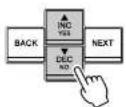
③ [▲INC/YES1/▼DEC/NO1 buttons
Rear Panel

text_image
Diagram of an electronic device rear panel with labeled ports and connectors, including a 3D network interface and I/O port.⑥ Ground screw
The AC power cord is a 3-wire type. If the AC outlet used is earthed (grounded), this device will be properly earthed as well. Also, grounding the screw sometimes reduces hum and interference noise.
⑦ [AC IN] connector
Connect to the AC mains using the supplied AC power cable.
First connect the power cord to the ACD1, then insert the power cord plug into an AC outlet.
⑧ [NETWORK] connector
This is a 100Base-TX/10Base-T Ethernet connector for connection to a computer or other device in the network.
NOTE • Use a UTP cable or STP cable for connection to the [NETWORK] connector. (Use an STP cable in countries where FCC regulations apply.) Since the ACD1 supports Auto MDI/MDI-X, it will automatically detect whether the connected cable is of the straight type or crossover type, and will configure itself to create the appropriate connection. Therefore, you can use either a straight or crossover cable.
• The maximum length of a cable between a network switch and the ACD1 is 100 meters. Due to the quality of cables and network switch performance, however, proper operation at the maximum length cannot be guaranteed in some cases.
⑨ [GPI] connector
This Euroblock connector provides access to the unit's GPI (General Purpose Interface) interface for transfer of control signals to and from external equipment. The ACD1 provides 4-port input and 4-port output. The +V terminals have an output voltage of 5 volts. The IN terminals detect voltage changes from 0V to 5V. The OUT terminals are open-collector outputs,
Panel operations
By pressing buttons on the panel you can monitor or control various parameters of the ACD1 itself or of the connected amplifiers.
The following parameters can be monitored/controlled.
| Category Sub category Operation performed | ||
| 1. Scene(page 10) | Recall Recalls a scene on the specified amplifier. | |
| Store Saves a scene for the specified amplifier. | ||
| 2. Amp Control(page 11) | On/Standby Switches the power of the specified amplifier between On and Standby. | |
| Mute Mutes or unmutes the channel of the specified amplifier. | ||
| Attenuation Adjusts the channel attenuator value of the specified amplifier. (PC-N/Tn series only) | ||
| 3. Output Monitor(page 12) | Displays the output level of the specified amplifier. | |
| 4. Device Setup(page 12) | Device ID Specifies the ACD1's Device ID address. | |
| Device Label Displays the name of the ACD1 assigned by Amp Editor. | ||
| Identify Blinks the "Identify" icon of the corresponding ACD1 in Amp Editor. | ||
| 5. Utility(page 13) | Battery Displays the state of the ACD1's internal backup battery. | |
| Firmware Ver. Displays the ACD1's firmware version. | ||
| LCD Backlight Selects whether the ACD1's LCD backlight will be always lit (ON) or lit only during operation (Auto OFF). | ||
| Panel Operation | Restricts panel operations of the ACD1. | |
| Scene Recall | Specifies whether scene recall from the ACD1's panel is enabled (Enable) or disabled (Disable). | |
| EMG Scene Setup | Specifies the scene number that will be recalled when the EMG (Emergency) signal is received from an external controller. If this is OFF, a scene will not be recalled even if an EMG signal is received. | |
| Last Mem. Resume | Specifies whether the ACD1 will start up with the settings that were in effect when the power was last turned off (ON) or whether it will start up by recalling the amp's scene number that was in effect when the power was last turned off (OFF). | |
| Clock | Sets the date and time of the ACD1's internal clock. | |
Panel operations
The main roles of each button are as follows.
| Button Role | ||
| [NEXT] Moves to the next screen or parameter. | ||
| [BACK] Moves to the previous screen or parameter. | ||
| [▲INC/YES] | Increments the value of a parameter (INC) or responds YES in response to a confirmation message. | |
| [▼DEC/NO] | Decrements the value of a parameter (DEC) or responds NO in response to a confirmation message. | |
| Press the [▲INC/YES] button | Press Increments the value of a parameter. | |
| Press and hold Continues to increment the value of a parameter while you hold down the button. | ||
| While holding, press the [▼DEC/NO] button | Increments the value faster than when you hold down the [▲INC/YES] button. | |
| Press the [▼DEC/NO] button | Press Decrements the value of a parameter. | |
| Press and hold Continues to decrement the value of a parameter while you hold down the button. | ||
| While holding, press the [▲INC/YES] button | Decrements the value faster than when you hold down the [▼DEC/NO] button. | |
Basic operation
As an example, we'll explain how to store the scene of an amplifier connected to the ACD1.
The basic operation is the same for all parameters.
- From the HOME screen, press the [NEXT] button and then use the [▲INC/YES]/[▼DEC/NO] buttons to select the [Scene] category.
NOTE • If the screen shows "Locked," the User Lock setting is set to "Panel." Enter the password to temporarily defeat User Lock. If no password has been specified, refer to "User Lock" (nana 14)
Panel operations
- Use the [▲INC/YES] / [▼DEC/NO] buttons to select the ID of the amplifier for which you want to store settings.
- Press the [NEXT] button to move to the scene number.
- Use the [▲INC/YES] / [▼DEC/NO] buttons to select the scene number that you want to store.
- Press the [NEXT] button to move to ⌘ ^1
- Press the [▲INC/YES] button to move to the screen where you can specify the scene name.
- Use the [▲INC/YES] / [▼DEC/NO] buttons to edit the first character of the scene name.
- Press the [NEXT] button to move to the next character of the scene name.
- Repeat steps 10 and 11 to edit the scene name.
Amp ID: 02 00Initial Data ^4
AMP ID: 02 000Initial Data4
AMP ID: 02 03: NO SCENE
AMP ID: 02 03:NO SCENE
03:Initial Data
03:initial Data
03:1initial Data
_7=1+_4-_2 _1
Scene ("1. Scene")
Here's how to recall or store scenes for a specified amplifier.
- Scene Recall
■ Recalling a scene ("1. Scene" → "Recall")
Recalls a scene for the specified amplifier.
Amp ID: 01 01:Scene Name
| Parameter Range | Explanation | |
| Amp ID 00–39, ALL Selects the ID of the amplifier for which to recall a scene. If you select “ALL,” the correspondingly-numbered scene will be recalled for all amplifiers. | ||
| Attributes of the scene | Preset scene | |
| A user scene that is protected | ||
| : | A user scene that is not protected | |
| Scene No. 00–49 Selects the scene number to be recalled. | ||
NOTE • If you select "ALL" as the Amp ID, the scene name will not be displayed.
- If you select "ALL" as the Amp ID, amplifiers for which there is no correspondingly-numbered scene data will not recall a scene; they will retain their previous state.
- Scene number 00 is for returning the amplifiers to their default settings.
- If characters not supported by the ACD1 were used for the scene name in Amp Editor, the corresponding locations will be shown as "III." For details on the characters supported by the ACD1, refer to "List of supported characters" (page 21) at the end of this manual.
- Scene names that can be displayed by the ACD1 are a maximum of 12 characters. If a scene name of 13 characters or longer is specified in Amp Editor, the ACD1 will not display the thirteenth and subsequent character.
- If you edit a parameter after recalling a scene, the E symbol (edit symbol) will be shown in screens that show the scene number.
Controlling an amplifier ("2. Amp Control")
These settings allow you to control an amplifier connected to the ACD1.
2.Amp Control Standby
■ Power on/standby ("2. Amp Control" → "Standby")
Switches the power of the specified amplifier between On and Standby.
Amp ID: 01 Standby
| Parameter Range Explanation | ||
| Amp ID 00-39, ALL Selects the ID of the amplifier whose power will be switched. If you select "ALL," the power of all amplifiers will be switched to the specified state. | ||
| Power supply status Standby/On Selects the status of the power supply. | ||
NOTE • If you select "ALL" as the [Amp ID], the power supply status may indicate "Some Standby." This means that the power is On for some amplifiers, and Standby for others.
■ Mute ("2. Amp Control" → "Mute")
Mutes or unmutes the channel of the specified amplifier.
Hmp Ch: A Muted
| Parameter Range Explanation | ||
| Amp ID 00-39, ALL Selects the ID of the amp | Whose channel is to be muted. If you select “ALL,” the mute status for all channels of all amplifiers will be switched. | |
| Amp Ch A-H, ALL Selects the channel whose | mute status is to be switched. The range of channels that can be selected will depend on the amplifier you select. If you select “ALL,” the mute | |
Amplifier output monitor ("3. Output Monitor")
This indicates the output level of the amp connected to the ACD1.
- Output Monitor
■ Amplifier output ("3. Output Monitor")
Displays the output level for each channel of the specified amplifier.
AMP ID: 01 A B
| Parameter Range | Explanation | |
| Amp ID 00-39 Selects the ID of the amp whose output level you want to view. | ||
| Level 0 Nothing will appear in the meter if the level is below 0 dBu. | ||
| 1 0-6 dBu | ||
| 2 6-16 dBu | ||
| 3 18-22 dBu | ||
| 4 22-28 dBu | ||
| 5 38-34 dBu | ||
| 6 48-41 dBu | ||
| 7 78 dBu- | ||
Device setup ("4. Device Setup")
Here you can make settings to identify the ACD1 connected to the network and the amplifiers connected to the ACD1.
- Device Setup
■ Identify ("4. Device Setup" → "Identify")
Blinks the "Identify" icon of the corresponding ACD1 in Amp Editor.
Identify
NO
| Parameter Range | Explanation | |
| Identify ON/OFF If this is [ON], the "Identify" icon of the corresponding ACD1 in Amp Editor will blink.Turning this [OFF] will defeat the blinking. | ||
Utility ("5. Utility")
Here you can make overall settings for the ACD1 and view various types of information.
- Utility
Battery
■ Backup battery check ("5. Utility" → "Battery")
Displays the state of the ACD1's internal backup battery.
Battery
OK
| Parameter Range Explanation | ||
| Battery OK Satisfactory. | ||
| Low Battery The battery is running low. | ||
| No Battery A battery is not installed, or has malfunctioned. The backup data has been lost. | ||
■ LCD backlight ("5. Utility" → "LCD Backlight")
This specifies the lit status of the ACD1's LCD backlight.
LCD Backlight ON
| Parameter Range Explanation | ||
| LCD Backlight ON The backlight will stay lit. | ||
| Auto OFF The backlight will go dark automatically.It will light when you perform a panel operation, and will automatically go dark ten seconds afterward. | ||
■ Restricting panel operations (“5. Utility” → “Panel Operation”)
Here you can turn panel operation lock on/off. By locking panel operations you can prevent unintended operation.
Panel Operation Normal 4
| Parameter Range Explanation | ||
| Panel Operation Normal Panel lock (locking of all panel operations) will be turned off. | ||
| View Only it will be impossible to edit parameters via the panel. It will be possible to switch the screen display. | ||
| Full Lock All panel operations other than temporarily defeating the panel lock will be disabled. | ||
NOTE • You can hold down both the [▲INC/YES] and [▼DEC/NO] buttons for approximately three seconds until the display indicates "Unlock panel: Are you sure?", then press the [▲INC/YES] button to temporarily defeat Panel Lock until the ACD1 is powered-off.
- You can also clear it by turning the Front Panel Operation setting Normal from Amp Editor.
■ Enabling scene recall operations from the panel ("5. Utility" → "Scene Recall")
This specifies whether scene recall by operating the ACD1's front panel will
■ Enabling scene recall operations via EMG commands
("5. Utility" → "EMG Scene Setup")
Specifies whether the EMG scene will be recalled when the EMG (Emergency) signal is received.
The following three types of EMG signal can be received.
• EMG command sent from AMX/Crestron
- Input signal to the GPI IN assigned to the Emergency scene
• EMG command sent from a different ACD1 unit
| Parameter Range | Explanation | |
| Amp ID 00-39, ALL Specifies the ID of the amp | for which EMG scene recall will be enabled. If you select "ALL," the EMG scene recall enable status of all amplifiers will be switched to the specified state. | |
| EMG Scene Setup 00-43 | Recalls the specified scene. | |
| OFF A scene will not be recalled even if an EMG signal is received. | ||
NOTE • If you select "ALL" as the [Amp ID], the EMG Scene Setup area may indicate "Some ON." This means that EMG scene recall is enabled for some amplifiers but disabled for other amplifiers.
■ LAST MEMORY RESUME setting ("5. Utility" → "Last Mem. Resume")
This specifies whether the unit will start up in the state in which it was powered-off, or recall the scene of the scene number that was selected at power-off.
| Last Mem.Resume |
| ON 4 |
| Parameter Range | Explanation | |
| Last Mem. Resume ON | The unit will start up in the state in which it was powered-off. | |
| OFF At start-up, the unit will recall the scene that was last recalled or stored before the power was turned off. | ||
■ Clock setting ("5. Utility" → "Clock")
■ GPI IN calibration ("5. Utility" → "GPI Calibration")
Calibrates the detected range of the [GPI IN] connector input voltage.
Port No.: 3 Min:3.40->4.20
| Parameter Range Explanation | ||
| Port No. | 1-4 | Selects the port of the [GPI IN] connector that will be calibrated. |
| Minimum/maximum value setting | Min/Max Selects whether you will be setting the minimum (Min) or maximum (Max) value for the input voltage. | |
| Voltage value -- Indicates the Input voltage. | At the left of the “->” symbol is shown the specified voltage (maximum/minimum value), and at the right is shown the current input voltage. When you confirm the setting, the current input voltage will be assigned as the maximum/minimum value. | |
Network settings ("6. Network Setup")
Here you can make network settings for the ACD1.
- Network Setup IP Address Mode
■ IP Address Mode setting ("6. Network Setup" → "IP Address Mode")
This specifies whether the ACD1's IP address will be set automatically by Amp Editor's Network Setup or a DHCP server, or manually.
IP Address Mode DHCE #
| Parameter Range Explanation | ||
| IP Address Marks | DHCP | The address will be not automatically. If you power off in this mode, the IP address |
■ Port settings for an external controller
("6. Network Setup" → "IP Ctrl Port #")
Here you can specify the port number that will be used to control the ACD1 from an external device such as an AMX or Crestron unit.
IP Ctrl Port # 49153
| Parameter Range | Port number (hexadecimal) | |
| Port No. | 49153-50049 | Specifies the ACD1's port number. Change the port number if there are other devices (other than the ACD1) that use the same port number. |
Initializing the ACD1
Here's how to initialize the ACD1's internal memory.

- When you initialize the internal memory, the content that had been saved in memory (scenes for each amp. and ACD1 settings) will be lost. Use caution when performing the following steps.
- Power-off the ACD1.

- While holding down the [BACK] button, turn the power on.


Connector wiring
This section explains how to wire the [GPI] and [FAULT OUTPUT] connectors located on the ACD1's rear panel.
Euroblock plug connection
Be sure to use the supplied Euroblock connector. If you lose the connector, contact your Yamaha dealer.
● Cable preparation
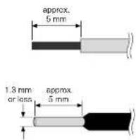
- To prepare the cable for attachment to a Euroblock connector, strip the wire as shown in the illustration, and use stranded wire to make connections. With a Euroblock connection, the stranded wire may be prone to breakage because of metal fatigue due to the weight of the cable or due to vibration. When rack-mounting your equipment, use a lacing bar when possible to bundle and fasten the cables.
- If cables will be frequently connected and disconnected, as in the case of a portable installation, we recommend that you use ferrules with insulation sleeves. Use a ferrule whose conductor portion has an external diameter of 1.3 mm or less, and a length of approximately 5 mm (such as the Al0.5-6WH made by the Phoenix Contact corporation).

- If you use stranded wire, do not tin (plate with solder) the exposed end.
1. Loosen the terminal screws.
NOTE • Use a slotted screwdriver with a blade approximately 2 mm wide.

text_image
2 mm Loosen Slotted screwdriver Euroblock plugGPI connector
Connect GPI (General Purpose Interface) devices (e.g., controllers) to the rear panel [GPI] connector.
You can use GPI to send or receive control signals to or from an external device.
GPI
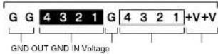
The ACD1 provides 4-port input and 4-port output.
- The +V terminals have an output voltage of 5 V. A maximum total of 100 mA of current can be drawn.
• The IN terminals detect voltage changes from 0 V to 5 V.
• The OUT terminals are open-collector outputs. A maximum voltage of +12 V can be applied. - F or each port, a maximum of 75 mA of current can flow.
- Use Amp Editor to make settings such as parameter assignments.
• A Euroblock plug is used for connection to the [GPI] connector.
Euroblock connection methods are described in "Euroblock plug connection" (page 18) in this manual.
NOTE • By specifying the input/output channels in Amp Editor, you can recall scenes or edit parameters from a connected external GPI device, or send signals to an external GPI device. For details on making settings, refer to the "Amp Editor owner's manual."
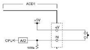
● Example : Controlling the ACD1 from a switch
text_image
ACD1 +5V CPU← A/D 100k +V IN● Example : Lighting the LED of an external device from the ACD1
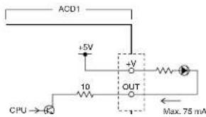
text_image
ACD1 +5V +V 10 OUT CPU → Q Max. 75 mAFAULT OUTPUT connector
You can connect a lamp etc. to the rear panel [FAULT OUTPUT] connector to indicate that an abnormality has occurred.
The [FAULT OUTPUT] connector consists of NO (Normally Open), C (Common), and NC (Normally Closed). The [FAULT OUTPUT] connector is a relay circuit, and operates as follows.
FAULT OUTPUT NO C NC
| Normal state Abnormal state Powered-off | ||
| NO Open Closed Closed | ||
| NC Closed Open Open |
The relay contacts used in the [FAULT OUTPUT] connector are rated for a load of 1A, DC 30V. Do not apply a load that exceeds this rating.
Use Amp Editor to make settings for the [FAULT OUTPUT] connector.
Euroblock plugs are used for the [FAULT OUTPUT] connector. Euroblock connection methods are described in "Euroblock plug connection" (page 18) in this manual.
NOTE In Amp Editor's [Device Setup] menu → [Alert Setup], you can set Type to Fault so that a fault can be indicated by a connected lamp, etc. For details on making settings, refer to the "Amp Editor owner's manual."
● Example : Using an LED to indicate normal/fault status of the ACD1
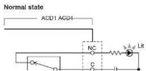
text_image
Normal state ACU1 AGD1 NC C Lit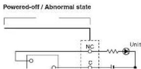
text_image
Powered-off / Abnormal state NC C UnitAppendix
Display messages
Messages that may appear in the ACD1's display and the appropriate responses are listed below. For more about alert messages, refer to the Amp Editor owner's manual.
| Message Response | |
| Panel locked! To prevent unintended operation, panel operations have been locked by the Panel Operation setting.To temporarily defeat Panel Operation, hold down both the [▲INC/YES] / [▼DEC/NO] buttons for atleast three seconds. To turn Panel Lock off, first defeat it temporarily, and then change the "5. Utility" → "Panel Operation" setting to Normal. | |
| Parameterlocked! | To prevent unintended operation, parameter editing has been locked by the Panel Operation setting.To temporarily defeat Panel Operation, hold down both the [▲INC/YES] / [▼DEC/NO] buttons for atleast three seconds. To turn Panel Lock off, first defeat it temporarily, and then change the "5. Utility" → "Panel Operation" setting to Normal. |
| Unlock panel:Are you sure? | This is displayed when you temporarily defeat User Lock.To defeat the setting, press the [▲INC/YES] button. |
| Scene storingDo not turn off! | A scene is being stored. Never turn off the power while this message is shown. |
| Cannot editwhile online! | Settings cannot be edited, because the unit is online with Amp Editor. |
| Scene protected! You cannot store to a protected scene. | |
| File writingDo not turn off! | A file is being written to internal memory. Never turn off the power while this message is shown. |
| InitializingDo not turn off! | Internal memory is being initialized. Never turn off the power while this message is shown. |
| Updating f/wareDo not turn off! | The firmware is being updated. Never turn off the power while this message is shown. |
| SynchronizingDo not turn off! | Now synchronizing with Amp Editor. Never turn off the power while this message is shown. |
| System error Initialize the memory. If this does not solve the problem, contact your Yamaha dealer. | |
| Saving failed | |
| Flash ROM error it is likely that the device has malfunctioned; please contact your Yamaha dealer. | |
Troubleshooting
| Symptom Possible causes Response | ||
| All scene data saved in the ACD1 has disappeared | The power was turned off while the ACD1's data was being saved | Once again synchronize the unit with Amp Editor to transmit the settings from Amp Editor. |
| The internal battery has run down | Go to "5. Utility" → "Battery" to check the battery status. If the indication is "Low Battery" or "No Battery," contact your Yamaha dealer listed at the end of the ACD1 owner's manual to have the battery replaced. | |
| Cannot edit parameters | Panel Lock is enabled | Change the "5. Utility" → "Panel Operation" setting to Normal, or use Amp Editor to defeat Panel Operation. |
| You are attempting to edit a parameter of an amplifier that is not connected | Connect the amplifier whose settings you want to change. | |
| The corresponding amplifier is not powered-on | Power-on the amplifier whose settings you want to change. | |
| Power will not turn on, display will not light | The power cable is not connected properly | Connect the power cable properly. |
| The POWER switch is not turned on Tum the POWER switch on. | ||
| The backlight setting is "Auto OFF" | If you want the LCD backlight to stay lit, turn the "5. Utility" → "LCD Backlight" setting "ON." | |
| Can't synchronize with Amp Editor | A cable is disconnected or broken Check whether a cable might be disconnected or broken. | |
| Amplifier does not operate as specified | The amplifier was powered-on before the ACD1 | Power-on the equipment so that the ACD1 starts-up before the amplifiers connected to the ACD1. |
| Can't monitor/control an amplifier | A cable is disconnected or broken Check whether a cable might be disconnected or broken. | |
| A cable exceeds the allowable length Make sure that the cable connected to the [MONITOR/REMOTE] connector is no longer than 50 meters.Make sure that the cable connected to the [DATA PORT] connector extends no longer than a total of 500 meters to its last point.Make sure that each individual cable between your computer | ||
Control I/O
| Terminal Format Level | Connector | |||
| MONITOR/REMOTE*1 | — | — | D-SUB 15R (Female) | |
| DATA PORT *2 | RS-485 RS-485 RJ-45 | |||
| GPI*3 | IN — 0—5 V | Euroblock (3.5 mm pitch) | ||
| OUT — Open Collector | ||||
| +V | — | 5 V | ||
| FAULT OUTPUT*4 | — | — | ||
| NETWORK | IEEE 802.3 | 10Base-T/100Base-TX | RJ-45 | |
*1 Supported models
XP7000, XP5000, XP3500, XP2500, XP1000, XM4180, XM4080, XH200
Guaranteed cable length: 50m
*2 Supported models
T5n, T4n, T3n, PC9501N, PC6501N, PC4801N, PC3301N, PC2001N, PC9500N, PC4800N, PC3300N
*3 Inputs: 4channels, Outputs: 4channels
Outputs: Withstanding Voltage Vmax = 12V (Open)
Outputs: Sink Current Imax = 75mA/pin (Closed)
+V: Imax =100mA/2pins
*4 Input: Imax = 1A, Vmax = 30VDC
Pin Assignment
■ MONITOR/REMOTE

| 1 | GND | |
| 2 | REMOTE CONTROL | STANDBY |
Appendix
Dimensions

text_image
51 354 362 3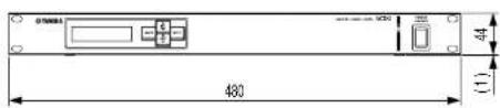
text_image
075001 480 (1) 44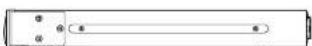
Unit: mm