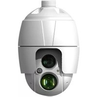
REHSPTZ30-1CM - Security Camera REVO - Free user manual and instructions
Find the device manual for free REHSPTZ30-1CM REVO in PDF.


| Product Type | 30x Full-HD IR Speed Dome Network Camera |
| Model | REHSPTZ30-1CM |
| Image Sensor | 1/2.8" SONY Exmor CMOS |
| Lens | 4.3mm ~ 129mm, 30x optical zoom, 16x digital zoom |
| Resolution | 1920 x 1080p (Full HD) |
| Max Frame Rate | 1080p@60/50fps, 1080p@30/25fps |
| Video Compression | H.264 (BP/MP/HP), MJPEG |
| Multiple Streaming | Triple stream (2x H.264 + 1x MJPEG) |
| Min Illumination | Color: 0.5 Lux, B/W: 0.1 Lux |
| IR Distance | Synchronized IR LED & Fixed IR LED |
| Day/Night | True D&N with IR-cut filter |
| Wide Dynamic Range | Yes (WDR) |
| Pan Range | 360° endless |
| Tilt Range | 0° ~ 180° |
| Preset Positions | 240 |
| Audio | 1 input, 1 output (G.711) |
| Alarm | 1 input, 1 output |
| Network Protocols | IPv4/IPv6, TCP/IP, UDP, HTTP, RTP, RTSP, NTP, DHCP, SMTP, DDNS, HTTPS, RTCP, FTP, Bonjour |
| Weatherproof Rating | IP66 |
| Power Supply | 12VDC ±10%, 5A (36W) |
| Operating Temperature | -20°C ~ 50°C (-4°F to 122°F) |
| Weight (Dome) | Approx. 4.9 kg |
| Dimensions | See manual for drawing |
| Included Accessories | Dome camera, installation guide/CD, RJ-45 coupler, 2P & 3P screw connectors, 12VDC adaptor |
| Maintenance | Clean with dry cloth; do not block ventilation; avoid moisture |
| Safety Compliance | FCC Class A, ICES-003, UL60950-1 |
Frequently Asked Questions - REHSPTZ30-1CM REVO
User questions about REHSPTZ30-1CM REVO
0 question about this device. Answer the ones you know or ask your own.
Ask a new question about this device
Download the instructions for your Security Camera in PDF format for free! Find your manual REHSPTZ30-1CM - REVO and take your electronic device back in hand. On this page are published all the documents necessary for the use of your device. REHSPTZ30-1CM by REVO.
USER MANUAL REHSPTZ30-1CM REVO
INSTRUCTION MANUAL REHSPTZ30-1

natural_image
Close-up of a white spherical security camera with green lens and mounted sensor (no visible text or symbols)REVO ELITE HD 30x Full-HD IR SPEED DOME NETWORK CAMERA
WARNING
TO REDUCE THE RISK OF FIRE OR ELECTRIC SHOCK, DO NOT EXPOSE THIS PRODUCT TO RAIN OR MOISTURE. DO NOT INSERT ANY METALLIC OBJECTS THROUGH THE VENTILATION GRILLS OR OTHER OPENINGS ON THE EQUIPMENT.
CAUTION

EXPLANATION OF GRAPHICAL SYMBOLS
The lightning flash with arrowhead symbol, within an
FCC COMPLIANCE STATEMENT
FCC INFORMATION: This equipment has been tested and found to comply with the limits for a Class A digital device, pursuant to Part 15 of the FCC Rules. These limits are designed to provide reasonable protection against harmful interference when the equipment is operated in a commercial environment. This equipment generates, uses, and can radiate radio frequency energy and, if not installed and used in accordance with the instruction manual, may cause harmful interference to radio communications. Operation of this equipment in a residential area is likely to cause harmful interference in which case the user will be required to correct the interference at his own expense.
CAUTION: Changes or modifications not expressly approved by the party responsible for compliance could void the user's authority to operate the equipment.
This Class A digital apparatus complies with Canadian ICES-003.
IMPORTANT SAFETY INSTRUCTIONS
- Read these instructions.
- Keep these instructions.
- Heed all warnings.
- Follow all instructions.
- Do not use this apparatus near water.
-
Clean only with dry cloth.
-
Do not block any ventilation openings. Install in accordance with the manufacturer's instructions.
-
Do not install near any heat sources such as radiators, heat registers, stoves, or other apparatus (including amplifiers) that produce heat.
-
Do not defeat the safety purpose of the polarized or grounding-type plug. A polarized plug has two blades with one wider than the other. A grounding type plug has two blades and a third grounding prong. The wide blade or the third prong is provided for your safety. If the provided plug does not fit into your outlet, consult an electrician for replacement of the obsolete outlet.
-
Protect the power cord from being walked on or pinched particularly at plugs, convenience receptacles, and the point where they exit from the apparatus.
-
Only use attachments/accessories specified by the manufacturer.
-
Use only with the cart, stand, tripod, bracket, or table specified by the manufacturer, or sold with the apparatus. When a cart is used, use caution when moving the cart/apparatus combination to avoid injury from tip-over.
13 Unplug this apparatus during lightning storms or when

TABLE OF CONTENTS
- Description....7
1.1 Components 7
1.2 Key Features....8
- Installation....9
2.1 Installation 9
2.2 Basic Configuration of Camera System.... 12
2.3 Connections.... 13
2.4 Network Connection & IP assignment 14
- Operation....15
3.1 Access from a browser.... 15
3.2 Access from the internet 16
3.3 Setting the admin password over a secure connection.... 16
3.4 Live View Page 16
3.5 Network Camera Setup.... 18
3.5.1 Basic Configuration.... 18
1) Users.... 19
2) Network.... 20
3) Video & Image 21
4) Audio....23
5) Date & Time 24
3.5.2 Live View 25
2) Tour 45
3) Motor Setup 46
4) RS485 47
5) View Angle....47
6) System Menu....48
7) Privacy Zone.... 49
3.5.7 System.... 50
1) Information .... 50
2) Security....50
3) Date & Time 52
4) Network....53
5) Language 61
6) Maintenance 62
7) Support 63
3.6 Help.... 65
3.7 Resetting to the factory default settings.... 65
- Appendix ......66
4.1 Troubleshooting 66
4.2 Alarm Connection 67
4.3 Preventive Maintenance 67
4.4 Product Specification 68
4.5 System Requirement for Web Browser....70
4.6 General Performance Considerations....70
1. Description
The network camera supports the network service for a sensor image with progressive scan, which can be monitored on a real-time screen regardless of distances and locations. By using its dedicated program, many users are able to have an access to the network camera at once or a single user can monitor various network cameras at the same time. It also enables users to play, store and retrieve a monitoring image by using a PC. All the settings and real-time monitoring screens are also provided through an access to the web.
The network camera is fully featured for security surveillance and remote monitoring needs. It is based on the DSP compression chip, and makes it available on the network as real-time, full frame rate Motion JPEG and H.264 video streams.
1.1 Components
This system comes with the following components;
Dome Camera....1
Installation Guide/CD....1
RJ-45 Coupler....1
2P screw type Connector....1
3P screw type Connector....1
12VDC Adaptor....1
1.2 Key Features
- Brilliant video quality
The network camera offers the highly efficient H.264 video compression, which drastically reduces bandwidth and storage requirements without compromising image quality. Motion JPEG is also supported for increased flexibility.
- Triple Streams
The network camera can deliver triple video streams simultaneously at full frame rate in all resolutions up to 1920 x 1080 using Motion JPEG and H.264. This means that several video streams can be configured with different compression formats, resolutions and frame rates for different needs.
• Image setting adjustment
The network camera also enables users to adjust image settings such as contrast, brightness and saturation to improve images before encoding takes place.
• Intelligent video capabilities
The network camera includes intelligent capabilities such as enhanced video motion detection. The network camera's external inputs and outputs can be connected to devices such as sensors and relays, enabling the system to react to alarms and activate lights or open/close doors.
- Improved Security
The network camera logs all user access, and lists currently connected users. Also, its full frame rate video can be provided over HTTPS.
• Built-in Synchronized IR LED & Fixed IR LED
The camera is equipped with two built-in IR LED's, fixed one for wide view and zoom synchronized adjustable one for distant view.
• ONVIF Certificate
This is a global interface standard that makes it easier for end users, integrators, consultants, and manufacturers to take advantage of the possibilities offered by network video technology.
2. Installation
2.1 Installation
You need one optional mount kit of the wall mount and the ceiling mount to install.
The wall or ceiling mount must be attached to a structural object such as hard wood, concrete that will support the weight of the mount and dome camera.
The use of a solid backboard is recommended when attaching to gypsum walls.
- Remove the Protection pad and the tape from attached the dome camera.
- Attach the mounting base to wall using the supplied M8 tapping screw and plastic bushing. (Ceiling using the supplied M6 tapping screw and bushing)
- Wind the both thread of the pipe end with Teflon tape about 20 times for sealing. Then use a silicone rubber sealant to seal the area where the wall (ceiling) mount and the pipe meet.
- Place a bead of silicone sealant around the wall and ceiling mount mounting flange, press it to the surface and line up the flange hole with drilled holes.
CAUTION 1: A silicone rubber sealant must be applied to seal the housing to secure waterproofing.
CAUTION 2: When installing, a bracket must be applied.
2.1.1 Installation - Wall Mount
The wall mounting plate must be attached to a structural object such as concrete that will support the weight of the mount and Dome Camera.
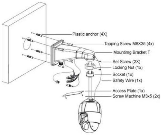
2.1.2 Installation - Ceiling Mount
The ceiling mounting plate must be attached to a structural object such as concrete that will support the weight of the mount and Dome Camera.
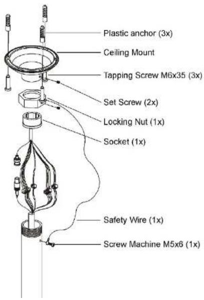
- Select a suitable mounting location and verify there is sufficient cable to connect with cables from the housing.
- Mark and drill mounting holes in the surface using the ceiling mount flange.
- Pull out cables required to connect to the dome camera from the ceiling.
- Attach the ceiling mount bracket using screws routing cables through the locking nut.
- Tighten the housing with the pipe using the socket after routing cables through the pipe.
- Attach the housing's safety wire to the ceiling mount's m6X35 tapping screw.
- After connecting cables, fix the pipe to the ceiling mount using the
2.2 Basic Configuration of Camera System
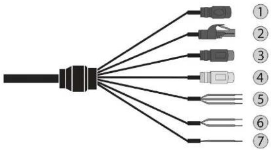
| No. | CONNECTOR | COLOR | DESCRIPTION |
| 1 | DC JACK BLACK 12VDC | ||
| 2 | RJ-45 BLACK | Ethernet, RJ-45 port compatible with 10/100Mbps | |
| 3 | RCA BLACK AUDIO INPUT | ||
| 4 | RCA GRAY AUDIO OUTPUT | ||
| 5 | 3P Cable | GRAY GND | |
| RED ALARM INPUT | |||
2.3 Connections
- Connecting the Network
Connect a standard RJ-45 cable to the network port of the camera. Generally a cross-over cable is used for directly connection to PC, while a direct cable is used for connection to a hub.
- Connecting Alarms
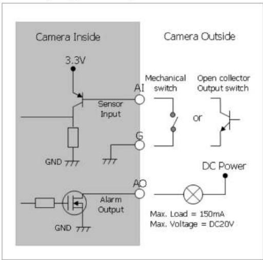
- AI (Alarm Input)
You can use external devices to signal the camera to react on events. Mechanical or electrical switches can be wired to the AI (Alarm Input) and G (Ground) connectors.
- G (Ground)
NOTE: All the connectors marked G or GND are common.
Connect the ground side of the alarm input and/or alarm output to the G (Ground) connector.
- AO (Alarm Output)
The camera can activate external devices such as buzzers or lights. Connect the device to the AO (Alarm Output) and G (Ground) connectors.
- Connecting to the RS485
The camera can be controlled remotely by an external device or control system, such as a control keyboard, using RS485 half-duplex serial communications signals.
- Connecting the Power
Connect power of 12VDC 5A for the camera.
Use satisfy clause 2.5 of IEC60950-1/UL60950-1 or Certified/Listed Class 2 power source only.
2.4 Network Connection & IP assignment
The camera supports the operation through the network. When a camera is first connected to the network, it has no IP address. So, it is necessary to allocate an IP address to the device with the "SmartManager" utility on the CD. (Default IP 192.168.30.220)
1) Connect the network camera/device to the network and power up.
2) Start SmartManager utility (Start > All programs > SmartManager > SmartManager). The main window will display, and after a short while any network devices connected to the network will be displayed in the list.
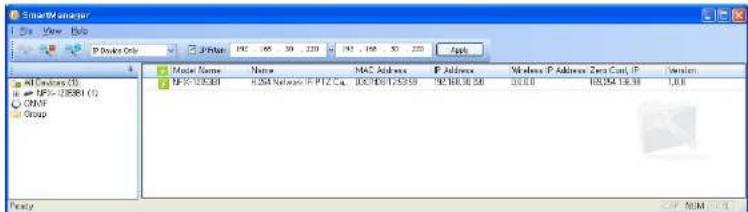
3) Select the camera on the list and click right button of the mouse. You can see the pop-up menu as below.

3. Operation
The network camera can be used with Windows® operating system and browsers. The recommended browsers are Internet Explorer®, Safari®, Firefox®, Opera™ and Google® Chrome® with Windows.
NOTE: To view streaming video in Microsoft Internet Explorer, set your browser to allow ActiveX controls.
3.1 Access from a browser
1) Start a browser (Internet Explorer).
2) Enter the IP address or host name of the network camera in the Location/Address field of your browser.
3) You can see a starting page. Click Live View or Setup to enter web page.
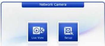
4) The network camera's Live View page appears in your browser.

natural_image
Interior view of a glass-enclosed building with exposed wooden trusses and skylights, no visible text or symbols.3.2 Access from the internet
Once connected, the network camera is accessible on your local network (LAN). To access the network camera from the Internet you must configure your broadband router to allow incoming data traffic to the network camera. To do this, enable the NAT traversal feature, which will attempt to automatically configure the router to allow access to the network camera. This is enabled from Setup > System > Network > NAT. For more information, please see "3.5.7 System > Network > NAT" of User's Manual.
3.3 Setting the admin password over a secure connection
To gain access to the product, the password for the default administrator user must be set. This is done in the "Admin Password" dialog, which is displayed when the network camera is accessed for the setup at the first time. Enter your admin name and password, set by the administrator.

NOTE: The default administrator user name and password is "admin". If the password is lost, the network camera must be reset to the factory default settings. Please see "Resetting to the factory default settings".
To prevent network eavesdropping when setting the admin password, this can be done via an encrypted HTTPS connection, which requires an HTTPS certificate (see NOTE below).
1) General controls

Live View Page

etup Page

Page

Stream 1
The video drop-down list allows you to select a customized or pre-programmed video stream on the Live View page. Stream profiles are configured under Setup > Basic Configuration > Video & Image. For more information, please see "3.5.1 Basic Configuration > Video & Image" of User's Manual.

1920×1080

The resolution drop-down list allows you to select the most suitable one out of video resolutions to be displayed on Live View page.

MTIP
The protocol drop-down list allows you to select which combination of protocols and methods to use depending on your viewing requirements, and on the properties of your network.

Preset
The preset drop-down list allows you to select the preset number for the PTZ camera being used. This icon is inactivated if the PTZ settings are not set.
2) Control toolbar
The live viewer toolbar is available in the web browser page only. It displays the following buttons:
The Stop button stops the video stream being played. Pressing the key again toggles the start and stop. The Start button connects to the network camera or starts playing a video stream.
The Pause button pauses the video stream being played.
The Snapshot button takes a snapshot of the current image. The location where the image is saved can be specified.
The Digital Zoom button activates a zoom-in or zoom-out function for video image on the live screen.
50 The Full Screen button covers the video image to fill the entire screen area. No other
3.5 Network Camera Setup
This section describes how to configure the network camera, and is intended for product. Administrators, who have unrestricted access to all the Setup tools; and Operators, who have access to the settings for Basic Configuration, Live View, Video & Image, Audio, Event, Dome Configuration, System
You can configure the network camera by clicking Setup in the top right-hand corner of the Live View page. Click on this page to access the online help that explains the setup tools.
When accessing the network camera for the first time, the "Admin Password" dialog appears. Enter your admin name and password, set by the administrator.
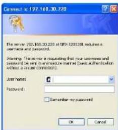
NOTE: If the password is lost, the network camera must be reset to the factory default settings. Please see "Resetting to the Factory Default Settings".
3.5.1 Basic Configuration
You can see the device information in this information page.

1) Users
User access control is enabled by default. An administrator can set up other users, by giving these user names and passwords. It is also possible to allow anonymous viewer login, which means that anybody may access the Live View page, as described below:
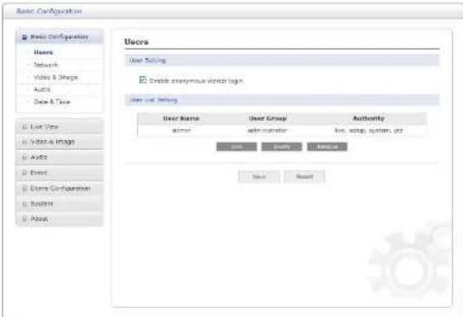
The user list displays the authorized users and user groups (levels):
| User Group Authority | |
| Guest | Provides the lowest level of access, which only allows access to the Live View page. |
| Operator | An operator can view the Live View page, create and modify events, and adjust certain other settings. Operators have no access to System Options. |
| Administrator | An administrator has unrestricted access to the Setup tools and can determine the registration of all other users. |
2) Network
The network camera supports both IP version 4 and IP version 6. Both versions may be enabled simultaneously, and at least one version must always be enabled. When using IPv4, the IP address for the network camera can be set automatically via DHCP, or a static IP address can be set manually. If IPv6 is enabled, the network camera an IP address according to the configuration in the network router. There is also the option of using the Internet Dynamic DNS Service. For more information on setting the network, please see "3.5.7 System > Network > Basic".
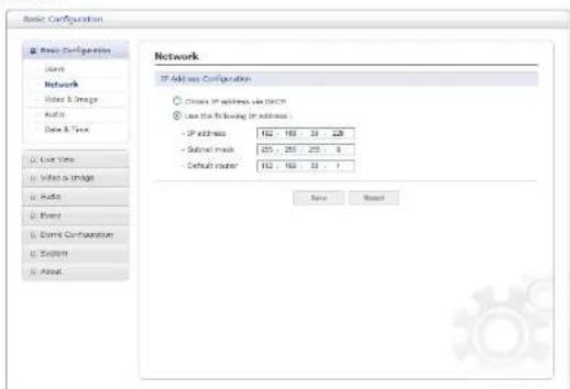
- Obtain IP address via DHCP: Dynamic Host Configuration Protocol (DHCP) is a protocol that lets network administrators centrally manage and automate the assignment of IP addresses on a network. DHCP is enabled by default. Although a DHCP server is mostly used to set an IP address dynamically, it is also possible to use it to set a static, known IP address for a particular MAC address.
- Use the following IP address: To use a static IP address for the network camera, check the radio button and then make the following settings:
3) Video & Image
![Basic Configuration Video & Image Marker Setting Capture mode: 1920x1000 Max. 20fps Stream 1 Setting Order: H:\264 Reference Profile Resolution: 1920x1000 Static control: CSS Address: 4381 (Phone) Parameters: 31 GCP size: 10 [1 - 50] Stream 2 Setting Order: H:\264 Reference Profile Resolution: 640x102 Instrument: 31 Quality: 10 [1 - 50] Stream 3 Setting Order: H:\264 Reference Profile Resolution: 640x102 Static control: CSS Address: 4381 (Phone) Parameters: 31 GCP size: 10 [1 - 50] Save Reset](/content/2026/06/1215972/images/6f64f02cc1c86faa4df028b0c300c51c42b60b69fed11065f7b76601ca4790fc.jpg)
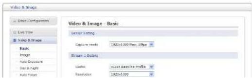
- Sensor Setting:
- Capture mode: Use can select video frame rate at either 60/50fps or 30/25fps of resolution 1920x1080.
- Stream 1 Setting:
- Codec: The codec settings are separated into H.264. H.264 is also known as MPEG-4 Part 10. This is the new generation compression standard for digital video. This function offers higher video resolution than Motion, JPEG or MPEG-4 at the same bit rate and
Users can reset the selected screen size anytime while monitoring the screen on a real-time basis.
- Bit rate control: Limiting the maximum bit rate helps control the bandwidth used by the H.264 video stream. Leaving the Maximum bit rate as unlimited maintains consistently good image quality but increases bandwidth usage when there is more activity in the image. Limiting the bit rate to a defined value prevents excessive bandwidth usage, but images are lost when the limit is exceeded.
NOTE: The maximum bit rate can be used for both variable and constant bit rates.
The bit rate can be set as Variable Bit Rate (VBR) or Constant Bit Rate (CBR). VBR adjusts the bit rate according to the image complexity, using up bandwidth for increased activity in the image, and less for lower activity in the monitored area.
CBR allows you to set a fixed target bit rate that consumes a predictable amount of bandwidth. As the bit rate would usually need to increase for increased image activity, but in this case cannot, the frame rate and image quality are affected negatively. To partly compensate for this, it is possible to prioritize either the frame rate or the image quality whenever the bit rate needs to be increased. Not setting a priority means the frame rate and image quality are equally affected.
- Bit rate: When it is necessary to adjust a smooth transmission status according to network situations, users can increase the compressibility to carry out the network transmission stably. On the other hand, when it is necessary to maintain a detailed monitoring screen by enhancing the image quality, users can do so by decreasing the compressibility. In each case, please adjust this function according to the network status and monitoring purposes.
- Frame rate: Upon the real-time play, users should select a frame refresh rate per second. If the rate is high, the image will become smooth. On the other hand, if the rate is low, the image will not be natural but it can reduce a network load.
- GOP size: Select the GOP (Group of Picture) size. If users want to have a high quality of fast image one by one, please decrease the value. For the purpose of general monitoring, please do not change a basic value. Such act may cause a problem to the system performance. For the details of GOP setting, please contact the service center.
4) Audio

The network camera can transmit audio to other clients using an external microphone and can play audio received from other clients by attaching a speaker. The Setup page has an additional menu item called Audio, which allows different audio configurations, such as full duplex and simplex.
- Audio Setting:
- Enable audio: Check the box to enable audio in the video stream.
- Compression type: Select the desired audio Compression format, G.711.
- Sample rate: Select the required Sample rate (number of times per second the sound is sampled). The higher the sample rate, the better the audio quality and the greater the bandwidth required.
- Sound bit rate: Depending on the selected encoding, set the desired audio quality (bit rate). The settings affect the available bandwidth and the required audio quality.
5) Date & Time
![Basic Configuration Basic Configuration Start Show Video & Image Audio Date & Time Live Time Video & Images Audio Print Lista Configuration System About Date & Time Current Server Time Date: 2015.10.28 Time: 16:55:42 New Server Time • Time slot [SPF] Greenwich Next Time ( Dublin, Dublinburg, London, London) • Automatically allocate for daylight saving time changes • Time mode • Switch ports with current time Date: 2015.10.28 Time: 16:55:42 • Switch ports with RTP server RTP server: 100/40 Hz MTP Internet: 12.99 (Direct) • Set memory Date: 2015.10.28 Time: 16:55:34 Data & Time format: Date format: YMM-400-03 Time Format: 24 Hour Save Reset](/content/2026/06/1215972/images/6195dd1e7bf20150a72e097323f9476738fa77a0b9b04d59d941868fb9633795.jpg)
- Current Server Time: This displays the current date and time (24h clock). The time can be displayed in 12h clock format in the overlay (see below).
- New Server Time: Select your time zone from the drop-down list. If you want the server clock to automatically adjust for daylight saving time, select "Automatically adjustment for daylight saving time changes".
From the Time mode section, select the preferred method to use for setting the time:
- Synchronize with computer time: sets the time from the clock on your computer.
- Synchronize with NTP Server: the video encoder will obtain the time from an NTP server every 60 minutes.
3.5.2 Live View
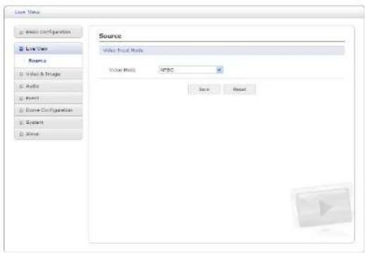
• Video Input Mode:
- Video Mode: Choose Video Mode you wish to use from the drop-down list: NTSC or PAL
3.5.3 Video & Image
1) Basic
2) Image
![Video & Image Audio Configuration Line Style Video & Image Sigma Image Auto Resources Copy & Light Auto Image OBS Visualizing Audio Insert Scene Configuration System Ours Image Properties Brightness 7 [default] Opacity 1 [default] High sensitivity: Off [default] Delay: Off [default] □ Create Text formatally Noise Solution Control Level 4 [default] Zoom Control Speed 6 [default] Digital Zoom: Off [default] Save Reset](/content/2026/06/1215972/images/9abc6618e9425886b8bc48bf79a1f3b1987747c6a12ed5d6843a2e4817862cac.jpg)
• Image Appearance:
- Brightness: The image brightness can be adjusted in the range 1 \~ 12, where a higher value produces a brighter image.
- Sharpness: Controls the amount of sharpening applied to the image. A sharper image
3) Auto Exposure
![Auto Exposure Auto Exposure Auto Features (SCH) Mode: Auto [default] Max Drop Rate: 21 [default] Info: 70 [default] Gain: 59 [default] Shotel: 160 [default] Show Number: CP [default] * Note: In manual exposure mode, stay & height will be set to the local mode. VDR Control Mode: CP [default] BUC Control Mode: CP [default] White Balance Setting Mode: Auto [default] R Gain: 12 [default] & Gain: 13 [default] Info Reset](/content/2026/06/1215972/images/5d5fd7272a95a3ca6694bf6b767b8ab7f53b74a12d33f556497dfbdd8a379926.jpg)
- WDR Control: Wide Dynamic Range (WDR) improves video exposure quality in scenes with high contrast between bright and dark areas, for example, if a shady area and a bright light area are in the same scene.
- Mode: Select On or Off.
- BLC Control: Backlight Compensation (BLC) corrects the exposure of the subjects that are in a bright light source.
- Mode: Select On or Off.
- White Balance Setting: Adjustments in the color hue (red and blue) gains for a camera so that true white appears white in the image. It is normally compensated for by the automatic gain control. In some lighting conditions, you may need to manually adjust the red and blue settings for optimal viewing. When Automatic White Balance is enabled, the camera measures the image and automatically adjusts the red and blue settings to balance white. When Automatic White Balance is disabled, the camera uses the values set for the red and blue settings to balance white.
- Mode:
* Auto: Computes the white balance value output using color information from the entire screen automatically.
* Manual: Manual mode, you can change R and B Gain manually.
- R Gain: The R gain can be adjusted in the range 0 \~ 255. This is only available if exposure mode is set to Manual.
- B Gain: The B gain can be adjusted in the range 0 \~ 255. This is only available if exposure mode is set to Manual.
4) Day & Night

- Day & Night Control: Select the day & night mode from among three modes.
- Mode:
* Automatic: Normally displays color image, and switches automatically to black & white image after the ambient light level reaches a pre-defined threshold.
* Dav: Always displays color image.
- Off level: Specify the illumination level that deactivates the IR mode. If the illumination is above the specified level, the indicator will turn off. (31 \~ 99)
- Fixed IR Bright: Specify the bright of the Fixed IR illuminator. (0 \~ 4)
- Moving IR Bright: Specify the bright of the Moving IR illuminator. (0 \~ 4)
- Delay: The duration of both the lighting conditions can be customized to let the IR divert between activation and deactivation. (1 \~ 60)
5) Auto Focus
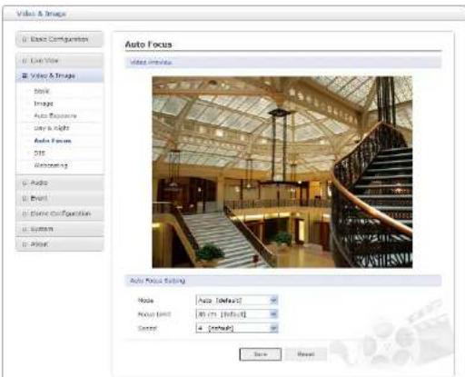
- Auto Focus Setting: Continuously adjusts the lens automatically to the correct focus for the sharpest picture.
6) DIS

- Digital Image Stabilization Setting: Controls DIS level from 0 to 9 and usage of 4 suppress: Local motion, Illumination, Plain background, and Slow motion.
7) Webcasting
The network camera can stream live video to a website. Copies the HTML code generated on the screen and pastes it in page code of the website you want to display live video.
Video & Image
3.5.4 Audio
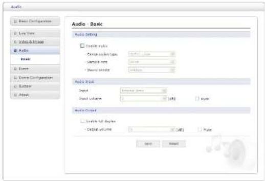
Refer to "3.5.1 Basic Configuration > Audio" for more details.
3.5.5 Event
1) Event In
▼ On Boot
![Event □ Event Configuration □ Live Time □ Video-Images □ Audio & Point □ Event In - On Boot Event In - On Boot □ Event Setting □ Create or boot □ Start Time [1, 20] sec Save Remove](/content/2026/06/1215972/images/0ddcb3a1b59e9c44b1afb7c5de69c36a0a29cb218a1b1aca693966a13d05d196.jpg)
▼ Alarm In
![Event Balance Configuration AutoView Video & Image Audio Event Event In Or Back Alerts To Reusal Trigger Rearful Network Loss Tuning Point Out Point Map Balance Configuration System Amount Event In - Alarm In Alarm in End - Eventing Enable Alert in Part 2 Type: L Dead Time: [1, 100] sec Save Reset](/content/2026/06/1215972/images/145986937686d44a35f62bf55c131fd99bd7b3a798f4057d932f7c2167591096.jpg)
This page allows you to configure the input supported by the camera. The Port can be given as Normally Open or Normally Close state, and their Normal state can be configured.
An input will be inactive as long as its Normal state equals its Current state. The 2 options for Normal state are NO (Normally Open) and NC (Normally Close). The input is activated when the Current state changes so that it no longer equals the Normal state.
- Alarm In Port 1 Setting:
Click the Enable alarm in port 1 checkbox to enable the Alarm In port 1.
- Type: The default setting is NO.
* NO: Normally Open
As an example, if the Normal state for a push button connected to an input is Open circuit, this means that as long as the button is not pushed (and the Current state remains as Open circuit), the state will be inactive.
▼ Manual Trigger
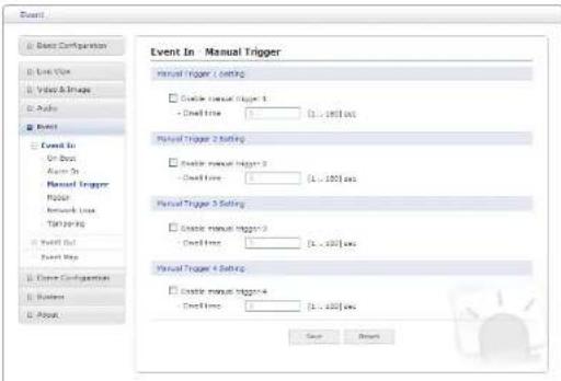
This option makes use of the Manual Trigger button provided on the Live View page, which is used to start or stop the event type manually. Alternatively, the event can be triggered via the product's API (Application Programming Interface).
▼ Motion
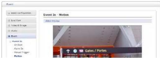
- Pre-Viewer: Motion detection windows are configured by Motion or Mask windows. Each window can be selected by clicking with the mouse. It is also possible to resize, delete or move the window, by selecting the appropriate window at the mouse menu on the video screen.
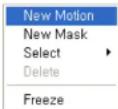
To create a motion or mask window, follow these steps:
- Click the right button of mouse to see the mouse menu.
- Select New Motion (or New Mask) from the mouse menu.
- Click and drag mouse to designate a motion area.
- Motion Detection Setting: The behavior for each window is defined by adjusting the Threshold and Sensitivity, as described below.
A motion index is a set of parameters describing Window Name, Type, Threshold and Dwell Time. Window Types is one of Motion and Mask windows.
- Threshold: Sets up the threshold for the motion detection.
- Dwell Time: Sets the hold time an event lasts for the specified hold time from the point of detection of a motion.
You can also modify or delete a motion index. Select an index and then, click the Modify or Delete button.
Select "Enable" to activate the motion window.
▼ Network Loss

▼ Tampering
![Event Basic Configuration Link View Video & Image Audio Event Event In: On Board Alarm Dr Reset Trigger Pock Network Loss Tampering Event Out Event Map Event Configurations System Output Event In : Tampering Tampering setting: Disable tampering - Credit Entry [1.. (10) test] Save Reset](/content/2026/06/1215972/images/d84488b269e612bbb80310f5db748bb890739e29235573a34231a67c106422b0.jpg)
This is used to trigger the event when camera tampering occurs. Select "Enable" to activate the Tempering event.
2) Event Out
▼ SMTP (E-Mail)
![Event □ Event Configuration □ Live Time □ Visible Image □ Audio □ Print □ Event ID □ Event Out SMTP(E-Mail) FTP & PDF Event Out - SMTP(E-Mail) SMTP (Mail) Setting □ Update Date Gender: □ Interval: 100 [...] (MIME) add Frequency events: 5x [...] (100) □ Use email server: □ Mail server:](/content/2026/06/1215972/images/23431035abb3dafa73219d88cd4df63570ee6dd5c9f53669f86d92615ed2fdf3.jpg)
- Mail Server/Port: Enter the host names (or IP addresses) and port numbers for your mail server in the fields provided to enable the sending of notifications and image email messages from the network camera to predefined addresses via SMTP.
- Sender: Enter the email address to be used as the sender for all messages sent by the network camera.
- Interval: Represents the frequency of the email notification when an event occurs.
- Aggregate events: Shows the maximum number of emails sent within each interval.
If your mail server requires authentication, check the box for use (SMTP) authentication to log in to this server and enter the necessary information.
- User name/Password: Enter the User name and Password as provided by your network administrator or ISP (Internet Service Provider).
To ensure that the login procedure is performed as securely as possible when using SMTP authentication, you must define the weakest authentication method allowed. - Login method: Set the Weakest method allowed to the highest/safest method supported by the mail server. The most secure method is listed in the drop-down list:
* AUTH LOGIN/AUTH PLAIN
• SMTP (E-Mail) Receiver:
- Receiver: Enter an email address. You can also register the e-mail address of up to 8 recipients.
- SMTP (E-Mail) Test:
- Receiver: Enter an email address and click the Test button to test that the mail servers are functioning and that the email address is valid.
▼ FTP & JPEG

NOTE: A DNS server must be specified in the TCP/IP network settings if using a host name.
- Port: Enter the port number used by the FTP server. The default is 21.
- Use passive mode: Under normal circumstances the network camera simply requests the target FTP server to open the data connection. Checking this box issues a PASV command to the FTP server and establishes a passive FTP connection, whereby the network camera actively initiates both the FTP control and data connections to the target server. This is normally desirable if there is a firewall between the camera and the target FTP server.
- Remote directory: Specify the path to the directory where the uploaded images will be stored. If this directory does not already exist on the FTP server, there will be an error message when uploading.
- User name/Password: Provide your log-in information.
- JPEG Setting:
- Pre-event: A pre-event buffer contains images from the time immediately preceding the event trigger. These are stored internally in the server. This buffer can be very useful when checking to see what happened to cause the event trigger.
Check the box to enable the pre-trigger buffer, enter the desired total length in seconds, minutes or hours, and specify the required image frequency. - Post-event: This function is the counterpart to the pre-trigger buffer described above and contains images from the time immediately after the trigger. Configure as for pre-event.
- Prefix file name: This name will be used for all the image files saved. If suffixes are also used, the file name will take the form
, , . - Additional suffix: Add either a date/time suffix or a sequence number - with or without a maximum value.
- HTTP Server Setting:
- Name: The name of the HTTP event server. Use a descriptive name.
- URL: The network address to the server and the script that will handle the request.
For example: http://192.168.12.244/cgi-bin/upload.cgi
- User name/Password: Provide your log-in information.
- HTTP Server Test: When the setup is complete, the connection can be tested by clicking the Test button.
▼ Alarm Out

- Enable alarm out: Click the Enable alarm out checkbox to enable the Alarm Out port.
- Type: The default setting is NO.
* NO· Normally Open
▼ Audio Alert
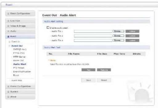
When the network camera detects an event, it can output predefined audio data to an external speaker. Check the box to enable the service.
- Audio Alert Setting: To use the Audio Alert with the network camera, an audio data file made by the user must be uploaded from your PC. Provide the path to the file directly, or use the Browse button to locate it. Then click the Upload button.
An audio file for Audio Alert can be made by Audio Recorder tool in the NCTitanium software.
- Audio Alert Test: When the setup is complete, the audio output can be tested by clicking the Test button.
To remove an audio file, select index and click the Remove button.
NOTE: For the proper operation of Audio Alert, you must enable "full duplex" on the Audio setting page.
▼ PTZ Preset

When the camera detects an event, you can move the camera to a predefined preset position. Check the box to enable the service and return to the Home position once the event has ended.
▼ Event Notification
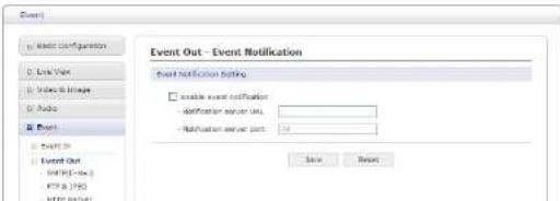
▼ Boost

The Boost feature is used in conjunction with event detection. When this feature is turned ON, the Frame rate and Bit rate in the boost condition can be set to a different value than the ones in the normal condition field. When an event is detected, the camera will boost the Frame rate and Bit rate from the normal condition to this boosted level for the duration of the event.
Check the box to enable the service.
- Boost Setting: You can set the condition in Normal and Boost mode.
- Boot Stream: Select a video stream for each condition in the drop-down list.
- Frame rate: Select a frame refresh rate per second for each condition in the drop-down list.
- Bit rate control: Select VBR or CBR in the drop-down list in Normal Condition. You can't change it in Boost Condition.
The event map allows you to change the settings and establish a schedule for each event trigger from the network camera. You can register the event map up to max. 15.
Click the Add button to make a new event map: a popup window display as below.
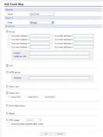
- General: Enter the name for a new event map.
- Event In: Select an event type in the drop-down list.
- Event Out:
- E-mail: Select the email addresses you want to notify via email that an event has occurred.
- FTP: Select checkbox beside FTP to record and save images to an FTP server when an
3.5.6 Dome Configuration
1) Preset
If you need to view specific places routinely, you should program Presets. A Preset is a programmed video scene with automatic pan, tilt, zoom and focus settings.
Once programmed, clicking the Preset number or clicking the Go button in the PTZ Control Panel calls up that Preset automatically.
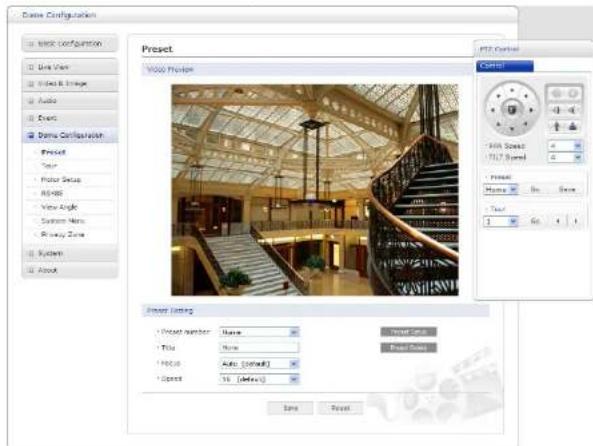
- Preset Setting:
- Preset number: The Preset number can be selected in the range 1 – 240 or Home.
- Title: Up to 12 characters (Alphanumeric characters and space)
2) Tour
There are 8 programmable Tours. Each Tour consists of up to 100 Presets.
![Crime Configuration ■ Basic Configuration ■ Low Size ■ Video & Image ■ Photo ■ Print ■ Crime Configuration ■ Image ■ Tower ■ New Setup ■ 8C485 ■ View Guide ■ System Menu ■ Summary Zone ■ System ■ After Tour Movie Preview Tour Room "Tour Name" 1 Size: 70x1 "Repeat" Continue [Default] "Sequence" Forward [Default] Save Reset Preview Help](/content/2026/06/1215972/images/5644b42f640094623eb3f7092c104f2dc3700379e1f0545313dadaa2a345c6a0.jpg)
- Tour Setting:
- Tour Number: The Tour number can be selected in the range 1 - 8.
- Title: Up to 12 characters (Alphanumeric characters and space)
- Repeat: Select number of repetition from Continuous to 90. The default is Continuous.
- Sequence: Select either forward or backward sequence in the Tour position list.
-
Delete Tour: Delete the stored Tour Position Setup list of Tour number.
-
Delete Position: If you want to remove Tour position from Tour Position Setup list, select the desired Tour Position, and click the Delete Position button.
- Set Position: Click the Set Position button, then show the stored Presets or Home on drop-down list.
Follow steps below to program the Tours:
- Click the desired Tour position of Tour Position Setup list, and click Set Position button, then show the saved Presets or Home on drop-down list. Click a Preset or Home.
- Repeat step 1 for each desired position.
- Click the Save button to save the settings, or click the Reset button to clear all of the information you entered without saving it.
3) Motor Setup
Motor Setup menu provides the pan and tilt speed of a camera.
![Core Configuration Basic Configuration Live View Video S Image Audio None Core Configuration Present Tour Motor Setup Assets View Mode System Many Privacy Zone System Power Motor Setup Proportional R/T on [Default] Save Cancel](/content/2026/06/1215972/images/8bc7f756ad3a7052c4dc72bd4994f5f017153e1c8778241d2966963d8e493882.jpg)
4) RS485

- RS485 Setting:
- DOME ID: Enter identification number for external PTZ device. The DOME ID can be adjusted in the range 1 \~ 3999.
- Protocol: Selects PTZ protocol to communicate with external PTZ device.
- Baud rate: Selects one of the Baud rate.
- Parity: Selects one of the Parity bit.
5) View Angle

- Flip:
* Off: The dome camera moves until 90° vertically.
* Auto: When the camera reaches the floor directly above the moving object, it will stop. At that time, release the Joystick instantly and pull it down again to run the auto-flip function. When you use the panning range, it is recommended to use the flip mode to Auto.
6) System Menu
![System Configuration □ Basic Configuration □ Left View □ Video Image □ Audio □ Drive □ Drive Configuration Preload Type Motor Setup Cutoff View Display System Name Primary Zone □ System □ Drive System Menu Core Information: Core type: < 3001-1000-25 Core Payload/Noted Version: [VCL 32/V2.02.034] Core Software Version: [VCL 34/28/06] System Menu setting: * D:\DOSA\ATOMET OFF Trigger Check: ■ Base Image the port and list positions: Copy Type: Save Reset](/content/2026/06/1215972/images/b1eb3157ab5392b80076a7e098ba8486b20661a42fa068ee012b20f1ebfb9015.jpg)
- Dome Information: The system information provides essential information about the dome if service is required. The information cannot be modified.
- System Menu setting:
- Dome Answer: Select On or Off for acknowledge command from the dome. This option is helpful to escape the collision of the command using some DVR.
7) Privacy Zone
s (masks), you can hide up to 8 unwanted scenes in a camera. The color of Using priva privacy zones is gray.
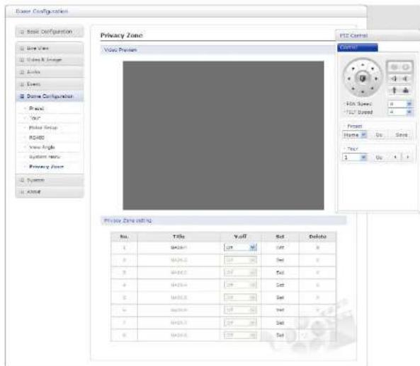
- Privacy Zone Setting: Following steps below to configure the privacy zones;
- After aiming the camera (view direction and lens control) by using the Arrow and Zoom button in PTZ Control Panel, click Set cell of Set column at any inactive row to create privacy zone.
3.5.7 System
1) Information
You can enter the system information. This page is very useful when you require device information after installation.

- Device Name Configuration: Enter the device name.
- Location Configuration: Enter the location information. You can enter up to four locations.
2) Security
▼ Users

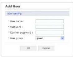
- User List Setting: This section shows how to register a user account. Enter a user name and password to be added, and register them by pressing the Add button. You will see the pop-up window as below.
▼ HTTPS

For greater security, the network camera can be configured to use HTTPS (Hypertext
▼ P Filtering I

Checking the Enable IP address filtering box enables the IP address filtering function. Up to 256 IP address entries may be specified (a single entry can contain multiple IP addresses). Click the Add button to add new filtered addresses.
When the IP address filter is enabled, addresses added to the list are set as allowed or denied addresses. All other IP addresses not in this list will then be allowed or denied access accordingly, that is, if the addresses in the list are allowed, then all others are denied access, and vice versa. Also see the online help for more information.
NOTE: Users from IP addresses that will be allowed must also be registered with the appropriate access rights. This is done from Setup > System > Security > Users.
3) Date & Time

- New Server Time: Select your time zone from the drop-down list. If you want the server clock to automatically adjust for daylight saving time, select "Automatically adjustment for daylight saving time changes".
From the Time mode section, select the preferred method to use for setting the time:
- Synchronize with computer time: Sets the time from the clock on your computer.
- Synchronize with NTP server: The network camera will obtain the time from an NTP server every 60 minutes.
- Set manually: This option allows you to manually set the time and date.
NOTE: If using a host name for the NTP server, a DNS server must be configured under TCP/IP settings.
4) Network
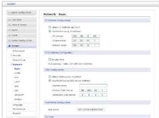
- Use the following IP address: To use a static IP address for the network camera, check the radio button and then make the following settings:
* IP address: Specify a unique IP address for your network camera.
* Subnet mask: Specify the mask for the subnet the network camera is located on.
* Default router: Specify the IP address of the default router (gateway) used for connecting devices attached to different networks and network segments.
- IPv6 Address Configuration: Check this box to enable IPv6. Other settings for IPv6 are configured in the network router.
- DNS Configuration: DNS (Domain Name Service) provides the translation of host names to IP addresses on your network.
- Obtain DNS Server via DHCP: Automatically use the DNS server settings provided by the DHCP server. Click the View button to see the current settings.
- Use the following DNS server address to enter the desired DNS server by specifying the following:
* Domain name: Enter the domain(s) to search for the host name used by the network camera. Multiple domains can be separated by semicolons (:) . The host name is always the first part of a Fully Qualified Domain Name, for example, my server is the host name in the Fully Qualified Domain Name myserver.mycompany.com where mycompany.com is the Domain name.
* DNS servers: Enter the IP addresses of the primary and secondary DNS servers.
- Host Name Configuration:
- Host Name: Enter the host name to be used as device information in the client software or SmartManager.
• Services:
- HTTP port:
Enter a port to receive a service through the HTTP. Default Port Number is '80'.
- HTTPS port:
▼ DDNS
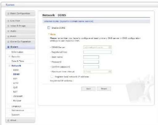
- Internet DDNS (Dynamic Domain Name Service): When using the high-speed Internet with the telephone or cable network, users can operate the network camera even on the floating IP environment in which IPs are changed at every access.
Users should receive an account and password by visiting a DDNS service like http://www.dyndns.com/ or http://www.cctv-network.co.kr/.
- Enable DDNS: Check to get DDNS service to be available.
* DDNS Server: Select the DDNS server.
* Registered host: Enter an address of the DDNS server.
* User name: Enter an ID to access the DDNS server.
* Password: Enter a password to be used for accessing the DDNS server
![System U: Network Configuration D: Link View E: Select & Image G: Audio H: Event I: Diverse Configuration B: System Information Details Data & Time Network Risk DC-OS RFP LMP QoS HAT Pyroconf Extrour Language Maintenance Support C: About. Network - RTP non-range Start port 1000 [1000... 3000] (only each value are available) First port 1000 Router (Stream 1) Enable multibus: - Multiple destination IP 256 ... 256 ... 256 [256.0.6.8... 259.255.255.255] FTP port 4000 [4000... 4000] only one user can be available - TCP TL 1 [1... 256] Enable always multibus: Multibus (Stream 2) Enable multibus: - Multiple destination IP 256 ... 256 ... 256 [256.0.6.8... 259.255.255.255] FTP port 4000 [4000... 4000] only one user can be available - TCP TL 1 [1... 256] Enable always multibus: Multibus (Stream S) Enable multibus: - Multiple destination IP 256 ... 256 ... 256 [256.0.6.8... 259.255.255.255] FTP port 4000 [4000... 4000] only one user can be available - TCP TL 1 [1... 256] Enable always multibus: Save Reset](/content/2026/06/1215972/images/521f87c37fa04776decd7ff23a9169e2746ce69d5e266b6e395c90df622f826b.jpg)
Use so can a co-cigures settings for sending and receiving audio or v These settings are the IP address, port number, and Time-To-Live value to use for t mediac team IP addresses and 264 number Only should be as the font in the script streams. For more information, plea
- Port Range:
- Start port: Enter a value between 30000 and 39920.
- End port: Enter a value between 30000 and 39920.
▼ UPnP

The network camera includes support for UPnP™. UPnP is enabled by default, and the network camera is then automatically detected by operating systems and clients that support this protocol.
NOTE: UPnP must be installed on your workstation if running Windows XP. To do this, open the Control Panel from the Start Menu and select Add/Remove Programs. Select Add/Remove Windows Components and open the Networking Services section. lect UPnP™ as the service to add. Click Details and then se
▼ QoS
Quality of Service (QoS) provides the means to guarantee a certain level of a specified resource to selected traffic on a network. Quality can be defined as a maintained level of bandwidth, low latency, and no packet losses.
The main benefits of a QoS-aware network are:
- The ability to prioritize traffic and thus allow critical flows to be served before flows with lesser priority.
- Greater reliability in the network, because of the control of the amount of bandwidth an application may use, and thus control over bandwidth races between applications.
![System □ Clean Configuration □ Look View □ Video & Image □ Audio □ NETT □ Llama Configuration ■ System Information □ Security Data & Time ■ Networks Basic DCSP ETF USB QoS NIT Z-Service Foguar UNIQ2020 Maintenance Support ■ Active Network - QoS DISCP Setting Use Open DISCP [0...65] MACs/Alert DISCP [0...65] Management DISCP [0...65] Automatic Traffic Control □ Enable automatic traffic control + Maximum Traffic control □ Automatic Traffic control Solve Cancel](/content/2026/06/1215972/images/c27d7ac72fc359c596f1e1670c432351dbfc74fb68a2af39089333e2cb814015.jpg)
- DSCP Settings: For each type of network traffic supported by your network video product, enter a DSCP (Differentiated Services Code Point) value. This value is used to mark the traffic's IP header. When the marked traffic reaches a network router or switch, the DSCP
▼ NAT
A broadband router allows devices on a private network (LAN) to share a single connection to the Internet. This is done by forwarding network traffic from the private network to the "outside," that is, the Internet. Security on the private network (LAN) is increased since most broadband routers are pre-configured to stop attempts to access the private network (LAN) from the public network/Internet.
Use NAT Traversal when your network cameras are located on an intranet (LAN) and you wish to make it available from the other (WAN) side of a NAT router. With NAT traversal property configured, all HTTP traffic to an external HTTP port in the NAT router is forward to the network camera.

flowchart
graph LR
    subgraph_WAN_WAN["Internet"]
        A["Computer"] --> B["WAN"]
        B --> C["Security Camera"]
        C --> D["Computer"]
    end
    subgraph_LAN_LAN["Intranet"]
        E["Security Camera"] --> F["Computer"]
    end
    G["Broadband (NAT) Router (Port Forwarding Device)"]
    H["Computer"] --> I["Security Camera"]
    I --> J["Computer"]
    style WAN_WAN fill:#f9f,stroke:#333
    style LAN_LAN fill:#ccf,stroke:#333
NOTES:
- For NAT traversal to work, this must be supported by the broadband router.
- The broadband router is known by many different names: "NAT router," "Network router," "Internet Gateway," "Broadband sharing device" or "Home firewall" but the essential purpose of the device is the same.

▼ Zeroconfig
Zeroconfig allows the network camera to create and assign the IP address for network cameras and connect to a network automatically.
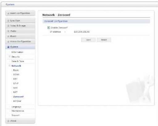
Zerbatonutgromaticallyedreatling (zeroconf) is a set of techniques t
usable Internet Protocol (IP) network without manual operator intervention or special iguration servers. conf
Zero configuration networking allows devices such as computers and printers to connect to a network automatically. Without zeroconf, a network administrator must set up services, such as Dynamic Host Configuration Protocol (DHCP) and Domain Name System (DNS), or configure each computer's network settings manually, which may be difficult and time-consuming.
Zeroconf is built on three core technologies:
▼ Bonjour
The network camera includes support for Bonjour. When enabled, the network camera is automatically detected by operating systems and clients that support this protocol.

NOTE: Bonjour - Also known as zero-configuration networking, Bonjour enables devices to automatically discover each other on a network, without having to enter IP addresses or configure DNS servers. Bonjour is a trademark of Apple Computer, Inc.
5) Language
Seeldathgualgesir

6) Maintenance
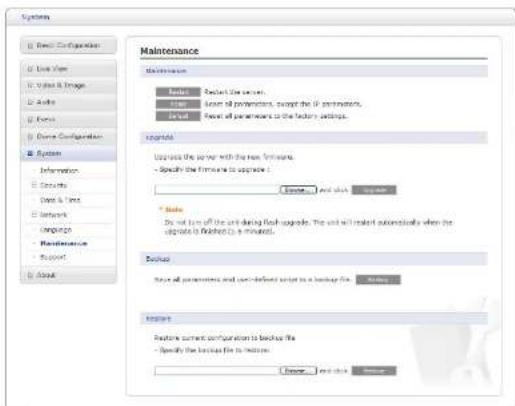
- Maintenance:
- Restart: The unit is restarted without changing any of the settings. Use this method if the unit is not behaving as expected.
- Reset: The unit is restarted and most current settings are reset to factory default values. The settings that are not affected are:
* the boot protocol (DHCP or static)
* the static IP address
* the default router
* the subnet mask
7) Support
The support page provides valuable information on troubleshooting and contact information, should you require technical assistance.
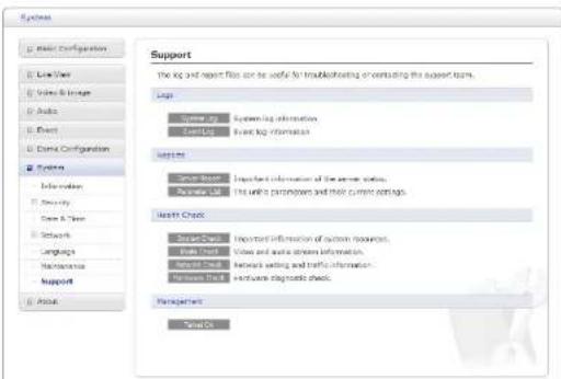
- Logs: The network camera supports system and event log information. Click the System Log button to get the system log data or the Event Log button to get information on events.
• Reports:
- ServerReport (DicktherServerReport) about the server's status; this should always be included when requesting support.
- Parameter List: Click the Parameter List button to see the unit's parameters and their current settings.
• Health Check:
- System Check: Click the System Check button to get the important information about the camera's system resources. You can see the pop-up window below.
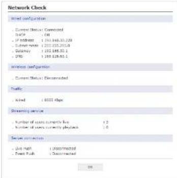
- Networks Check: Click the Network Check button to get the information about the camera's network setting and traffic. You can see the pop-up window below.
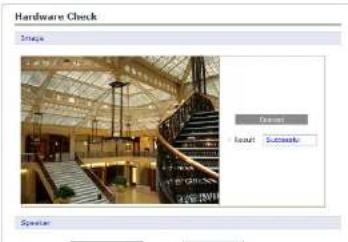
- Hardware Check: Click the Hardware Check button to diagnose the camera's hardware like video.
3.6 Help
The Help information window will be provided as a popup window so that users can open and re it without needing to log-in. It will offer a description of the setting and Help page so that users can manipulate the network camera without a reference to the manual.

3.7 Resetting to the factory default settings
To reset the network camera to the original factory settings, go to the Setup > System >
4. Appendix
4.1 Troubleshooting
Troubleshooting if problems occur, verify the installation of the network camera with the instructions in this manual and with other operating equipment. Isolate the problem to the specific piece of equipment in the system and refer to the equipment manual for further information.
| Problems/Symptoms Possible Causes or Corrective Actions | |
| The camera cannot be accessed by some clients. | If using a proxy server, try disabling the proxy setting in your browser. Check all cabling and connectors. |
| The camera works locally, but not externally. | Check if there are firewall settings that need to be adjusted. Check if there are router settings that need to be configured. |
| Poor or intermittent network connection. | If using a network switch, check that the port on that device uses the same setting for the network connection type (speed/duplex). |
| The camera cannot be accessed via a host name. | Check that the host name and DNS server settings are correct. |
| Not possible to log in. | When HTTPS is enabled, ensure that the correct protocol (HTTP or HTTPS) is used. When attempting to log in, you may need to manually type in http or https in the browser's address bar. |
| No image using Refresh and/or slow updating of images. | If images are very complex, try limiting the number of clients accessing the camera. |
| Images only shown in black & white. | Check the Video & Image setting. |
| Blurred images. Refocus the camera. | |
| Poor image quality. | Increased lighting can often improve image quality. Check that there is sufficient lighting at the monitored location. Check all image and lighting |
4.2 Alarm Connection
he following connection diagram gives an example of how to connect a network camera. T
4.8 Maive bacteria nce
Preventive maintainers d
etection and correction of minor that faults before they become
4.4 Product Specification
30x Full-HD IR SPEED DOME NETWORK CAMERA
| MODEL 30x | |
| IMAGE | |
| Image Sensor | 1/2.8" SONY Exmor CMOS |
| Lens | 4.3mm ~ 129.0mm30x A/F Optical Zoom, 16x Digital Zoom |
| Scanning Mode | Progressive Scan |
| Min. Illumination | Color: 0.5Lux, B/W: 0.1Lux |
| AE/AWB | Yes |
| DNR | Yes |
| D&N | True D&N (IR-cut filter) |
| WDR | Yes |
| DIS | Yes |
| BLC | Yes |
| Built-in IR | Synchronized IR LED & Fixed IR LED |
| VIDEO | |
| Progressive Encoding | Yes |
| Compression | H.264 (BP/MP/HP), MJPEG |
| Resolution Supported | 1920 x 1080p |
| Max. Frame Rate | 1080p@60/50fps, 1080p@30/25fps |
| Multiple Streaming | Triple Stream (2x H.264 and 1x MJPEG) |
| IN/OUT | |
| Audio In/Out | In x 1 / Out x 1 (G.711) |
| Alarm In/Out | In x 1 / Out x 1 |
| NETWORK | |
| Max. Connections | 10 |
| Protocols | IPv4/IPv6, Manual, TCP/IP, UDP, HTTP, RTP, RTSP, NTP, DHCP, SMTP, DDNS, HTTPS, RTCP, FTP, Bonjour |
| NAS Support | Yes |
| JPEG push | Yes |
| DDNS | Yes |
| Remote Client | Web browse CTitanium r, SmartManager, N |
| Installation Tool | SmartManager, NCTitanium |
| MISCELLANEOUS | |
| Weatherproof | IP66 |
| Power | 12VDC ± 10% |
| Power Consumption | 3.0) A (36W |
| Operating Temperature | -20°C ~ 50°C (-4°F to 122°F) |
| Operating Humidity | 0 ~ 90% RH |
| External Dimension | See dimension drawing |
| Weight | Approx. 4.9 kg for dome |
| PTZ FUNCTION | |
| Pan Range | 360° Endless |
| Pan Speed | Preset: Max. 380°/sec, Manual: Max. 380°/sec |
| Tilt Range | 180° (0° ~ 180°) |
| Tilt Speed | Preset: Max. 380°/sec, Manual: Max. 300°/sec |
| Preset | 240 |
* Specifications subject to change without notice *
4.5 Reinstatement for Web Browser
- Operating System: Microsoft Windows OS Series
- CPU: Intel Core 2 Duo 2Ghz or higher, 1GB RAM or more, 10GB free disk or higher
• VGA: AGP, Video RAM 32MB or higher (1024x768, 24bpp or higher)
4. Peróvenaltie Considera
When setteg up is important to continue and is in will after performance affect the amount of bandwidth (the bit rate) required, others can affect them and some affect both. If the load on the CPU reaches its maximum, this will also be affected the fr
The following factors are among the most important to consider:
- High image resolutions and/or lower compression levels (or high bitrates) result in larger images. Frame rate and Bandwidth affected.
- Accessing both Multicable ESGyA Fardh204 Atended streams sim bandwidth affected.
- Heavy network utilization due to poor infrastructure. Frame rate and Bandwidth affected.
- Heavy network utilization via wireless router due to poor infrastructure. Frame rate and bandwidth affected.
- Viewing orepopercapertepintoclimt@CEIarnectate affe

REVO ELITE HD
30x Full-HD IR SPEED DOME NETWORK CAMERA
- WARNING
- CAUTION
- EXPLANATION OF GRAPHICAL SYMBOLS
- FCC COMPLIANCE STATEMENT
- IMPORTANT SAFETY INSTRUCTIONS
- TABLE OF CONTENTS
- Description
- Components
- Key Features
- - Brilliant video quality
- - Triple Streams
- • Image setting adjustment
- • Intelligent video capabilities
- - Improved Security
- • Built-in Synchronized IR LED & Fixed IR LED
- • ONVIF Certificate
- Installation
- Installation
- Installation - Wall Mount
- Installation - Ceiling Mount
- Basic Configuration of Camera System
- Connections
- - Connecting the Network
- - Connecting Alarms
- - AI (Alarm Input)
- - G (Ground)
- - AO (Alarm Output)
- - Connecting to the RS485
- - Connecting the Power
- Network Connection & IP assignment
- Operation
- Access from a browser
- Access from the internet
- Setting the admin password over a secure connection
- 1) General controls
- 2) Control toolbar
- Network Camera Setup
- Basic Configuration
- 1) Users
- 2) Network
- 3) Video & Image
- - Sensor Setting:
- - Stream 1 Setting:
- 4) Audio
- - Audio Setting:
- 5) Date & Time
- Live View
- Video & Image
- 1) Basic
- 2) Image
- • Image Appearance:
- 3) Auto Exposure
- - Mode:
- 4) Day & Night
- 5) Auto Focus
- 7) Webcasting
- Audio
- Event
- 1) Event In
- ▼ Alarm In
- - Alarm In Port 1 Setting:
- ▼ Manual Trigger
- ▼ Motion
- ▼ Network Loss
- ▼ Tampering
- 2) Event Out
- ▼ SMTP (E-Mail)
- - JPEG Setting:
- - HTTP Server Setting:
- ▼ Alarm Out
- ▼ Audio Alert
- ▼ PTZ Preset
- ▼ Event Notification
- ▼ Boost
- Dome Configuration
- 1) Preset
- - Preset Setting:
- 2) Tour
- - Tour Setting:
- 3) Motor Setup
- 4) RS485
- - RS485 Setting:
- 5) View Angle
- - Flip:
- 6) System Menu
- - System Menu setting:
- 7) Privacy Zone
- System
- 1) Information
- 2) Security
- ▼ Users
- ▼ HTTPS
- ▼ P Filtering I
- 3) Date & Time
- 4) Network
- ▼ DDNS
- ▼ UPnP
- ▼ QoS
- ▼ NAT
- NOTES:
- ▼ Zeroconfig
- ▼ Bonjour
- 5) Language
- 6) Maintenance
- - Maintenance:
- 7) Support
- • Reports:
- • Health Check:
- Help
- Resetting to the factory default settings
- Appendix
- Troubleshooting
- Alarm Connection
- Maive bacteria nce
- Product Specification
- Reinstatement for Web Browser
- Peróvenaltie Considera
Brand : REVO
Model : REHSPTZ30-1CM
Category : Security Camera