CCM 4VP - Microphone Schoeps - Free user manual and instructions
Find the device manual for free CCM 4VP Schoeps in PDF.

User questions about CCM 4VP Schoeps
0 question about this device. Answer the ones you know or ask your own.
Ask a new question about this device
Download the instructions for your Microphone in PDF format for free! Find your manual CCM 4VP - Schoeps and take your electronic device back in hand. On this page are published all the documents necessary for the use of your device. CCM 4VP by Schoeps.
USER MANUAL CCM 4VP Schoeps
natural_image
Illustration of multiple pink cylindrical electronic components arranged in a diagonal pattern against a solid red background (no text or symbols)SCHOEPS
Mikrofone

CCM
Compact Microphones
Contents
page
System overview 2
Compact Microphones 3
Phantom powering 4
EMC, Technical specifications 6
Block diagram
Microwave selection #
Basic microphone characteristics 9
Suggested microphones for specific applications 10
Pressure (producers 17
Pressure-gradient transducers 12
Switchable micropage 16.
Micronphones for close pickets 17
Acoustic specifications of the microplanes 19
Care and maintenance / Unobligatory 20
(Ⅲ) 1. 定义性与性质
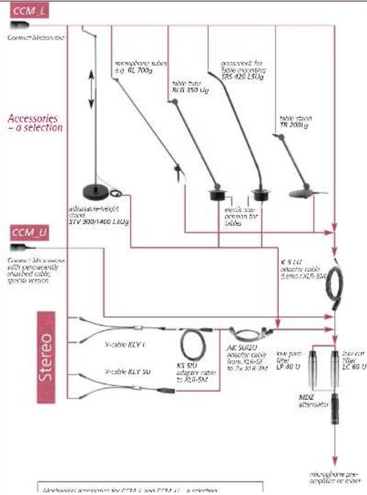
System Overview - A Selection
SCHOEPS
Mikrofone

flowchart
graph TD
    A["CCM_L"] --> B["Connect Mismatch"]
    B --> C["Accessories - a selection"]
    C --> D["membrane nubes e.g. RL 700g"]
    D --> E["table tube RL G 350 Kg"]
    E --> F["passed for table mounting RS 420 L50g"]
    F --> G["table tube TR 2000g"]
    G --> H["adequate height stamp STV 900/1400 L50g"]
    H --> I["weak compression for sales"]
    I --> J["K 510 auxiliary cable 260x ACR 540V"]
    K["CCM_U"] --> L["Connect Mismatch with permanently attached cable spousi version"]
    L --> M["Stereo"]
    M --> N["Y-cable KLY C"]
    M --> O["Y-cable KLY SU"]
    M --> P["KS 500 adapter cable to ADR-5M"]
    P --> Q["AK SU20 auxiliary cable from KA-SF to Zn XR-3M"]
    Q --> R["low-pass 15W LP 40 V"]
    R --> S["MDZ attenuator"]
    S --> T["microphone pre-acetylation or motor"]
CCM Compact Microphones
SCHOEPS
Mikrofone

Dear customer:
Thank you for choosing a SCH0EPS CCM Compact Series microphone.
CCM microphones are the smallest true classic condenser microphones (no electret used) offering the highest possible sound quality without compromise.
The following pages contain technical information, application suggestions and advice concerning the care and maintenance of these microphones.
CCM Compact Microphones ...
- are classic condenser microphones that do not require electronic frequency response correction
– have a balanced, low-impedance output – are for universal use
- are small and light
- have an extremely flat frequency response - their sound is extensively independent of direction
- have low noise and distortion - run on both 12 V and 48 V phantom feed power supplies
can be used with very long cables (over 100 meters)
Included accessories:
SGC miniature swivel stand coupler, polished wood carrying case,
CCM_L: K 5 LU adapter cable (Lemo / XLR-3M), 5 m long
As with SCHOEPS' Colette modular microphones, a compact microphone essentially consists of two main components: an acoustic transducer (a capsule) and a microphone amplifier. There only come together in the
microphone. The amplifier is the other main component, with the circuitry required to accept external powering, polarize (charge) the capacitive capsule, obtain the audio signal from it, and convert that signal into one which is balanced and low-impedance.
The circuitry of the Compact Microphones features a balanced, class-A output stage which does not use either coupling condensers or an output transformer. This leads to low output impedance, insensitivity to electrical interference, low distortion and light weight.
The Compact Microphones have a bass roll-off filter with a low cut-off frequency of 20Hz and a slope of 12 dB/oct.
This frequency has been chosen to protect against perturbing, inaudible (infra-) sound that can be caused by ventilation systems, track vehicles and wind. What is tricky about this is that although it is hardly noticeable, infrasound can cause strong audiole distortions in the connected equipment when it leads to an overload. This would make it impossible to produce a recording that could be used. The audio range also only starts at around 20Hz. Lower frequencies are only actually discernible at high levels which are only reproducible on few audio systems, and then quickly become unpleasant.
Start up
The U-version of the CCM Compact Microphone has a permanently attached cable that terminates to a standard XLR-3M connector. These microphones can be connected directly to the corresponding microphone inputs. To connect the L version (L= Lemo), the supplied K 5 LU cable plugs into the CCM Lemo socket. The K 5 LU cable is terminated with a standard XLR-3M connector. Put the cable's Lemo plug into the microphone port. Secure it so that the plug is not inadvertently pulled out or does not little while in two miles
Phantom Powering
SCHOEPS
Mikrofone

Phantom powering
CCM microphones are electrically active components which require operating current. This will most often be supplied by the inputs of a mixer, preamplifier or recorder with suitable microphone powering built-in. Otherwise, an appropriate type of stand-alone microphone power supply can be used.
Like most modern, solid-state professional microphones, the CCM also uses a standardized powering scheme known as "phantom powering." Most recording equipment offers a 48-Volt supply for such microphones. Some equipment, however, provides a 12-Volt supply for phantom powering, or can readily be modified for such a supply. The SCHEPS CCM compact microphones series can work with either voltage, switching its circuitry automatically to the corresponding mode of operation. It maintains the same level of performance in either mode while drawing only the necessary amount of current from the phantom supply. Please note that the CCM compact micro-
phones are designed to work with standard 12-Volt or standard 48-Volt phantom powering. They are therefore not "12 - to - 48 Volt" microphones. Any input to which it is connected must implement one of those two standard phantom powering methods, which means that not only must the supply voltage meet the standard, but the resistors must be correct as well.
Our microphones are developed and tested with power supplies that conform to the requirements of this standard. Proper operation with non-standard power supplies cannot be guaranteed. Circuit arrangements that deviate from the standard can cause operational problems (i.e., distortion or even gaps in the signal), particularly at high sound pressure levels or in the presence of strong wind noise. Such problems may often seem to defy analysis until their real cause is discovered. You can find out more about phantom power supplies below.
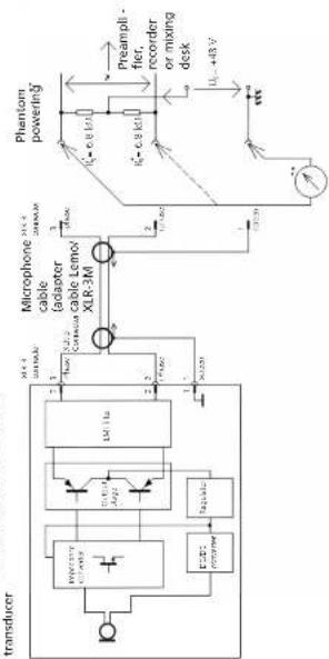
Fig. 1
input with transformer for balanced, ungrounded transformers input
flowchart
graph TD
    A["Phase"] --> B["X18 % Connector"]
    B --> C["Output"]
    D["Phase"] --> E["Output"]
    E --> F["Component 1"]
    F --> G["Component 2"]
    G --> H["Output"]
    I["Input"] --> J["External Circuit"]
    J --> K["Output"]
P^2 、 L_5=430^=4V 、 R_2=6.8k^2 、 I_pH2=10m^2
F12: L_3 = 12V ± 10,8 = 680 MPa, I_max = 15 m ^4
* see note in the text concerning tolerances
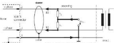
Fig. 2
balanced, ungrounded, transformer's input Condensers must be visited into the circuit and provision made for

text_image
phase XLR 3 connector phase switch 10^2 10^2 10^2 C + - + - + - + - + - + - + - + - + - + - + - + - + - + - + - + - + - + - + - + - + - + - + - + - + - + - + - + - + - + - + - + - + - + - + - + - + - + - + - + - + - + - + - + - + - + - + - + - + - + - + -Phantom Powering (continued)
SCHOEPS
Mikrofane

Phantompoweringtostandard DIN EN 61938
Correct powering is essential. There have been various myths and misunderstandings about it. Authoritative information is contained in the standards documents, but few people have access to them which is why we are offering this detailed explanation.
Phantom powering is designed to be "invisible" and harmless to balanced microphones which were not specifically designed to use it; this includes most balanced, professional dynamic and ribbon microphones, as well as condenser microphones that use vacuum-tube circuitry. Exceptions are quite rare. The only likely cases in which standard phantom powering will endanger a balanced microphone (e.g., a ribbon) are if a microphone cable, con nector or adapter is defective or wired in a non-standard way, such that one modulation lead of the microphone is shorted to ground at DC while the powering is on. If a microphone is connected to such a cable with the powering turned on, impulse current will flow through its coil or ribbon, possibly causing damage.
Fig. 1 shows the only valid 48V and 12V phantom powering circuit (abbreviations, P48 and P12) that can be realized with resistors as opposed to a center-tapped input transformer. This illustration is based on the international standard document LN 51938 of 1997.
The permissible tolerance of the feed resistor values as such is ± 20% . However, the difference between the resistors of any one pair should be less than 0.4% (i.e. 27 Ohms for 48-Volt phantom powering with 6.8 kOhm). This close matching is necessary to maintain adequate impedance balance for the sake of common mode rejection. It also avoids the flow of DC in an input transformer should one be present, which could lead to distortion or a reduced dynamic range.
6 micrometers designed for all worksets
plies, preamplifiers, and mixing desks - mostly older, but some more recent - which fail to meet this standard and hence may not be able to power SCHOEPS microphones adequately. If in doubt, equipment should be checked to verify its suitability for professional work with SCHOEPS microphones. On page 7 a method is described for checking a phantom supply quickly and easily.
For P12 the standard allows a current of 15 mA. A SCH0EPS CCM will draw 8 mA.
Fig. 2 shows a balanced but grounded amplifier in put. In this case eit her a trans for mer (see fig. 1) or additional capacitors have to be in ser ted into the au dio li ne.
Unbalanced Operation
Our microphones are intended for balanced operation, which is why they should be operated with balanced inputs. Otherwise the vulnerability to interference would be increased. However some equipment only has unbalanced inputs in which case an unbalanced input should be balanced with a high-quality microphone input transformer. This will allow the signal leads from the microphone to be kept balanced, for best rejection of interference.
If such an arrangement is not possible, however, a CCM microphone may be operated in unbalanced mode by taking the signal from pin 2 via a coupling condenser with a value as shown in Figure 2 above. The signal from pin 3 should be left unconnected, do not short it to ground. This "unbalancing act" must occur between the power supply and the preamplifier input, however, since naturally all three pins of the microphone must still connect to its phantom or parallel power supply.
Simultaneous Connection to Multiple Inputs If a microphone has to be connected to multiple inputs simultaneously, an active micro phone splitter should be used in order to preserve the leading and powering conditions for the
EMC, Technical Specifications
SCHOEPS
Mikrofone

capacitance of the cable, which is sometimes an unknown quantity. The lower this capacitance is per unit length, the longer the cable can be. All SCHOLPS cables have very low capacitance (100 pF/m between the conductors).
The main risks with excessively long microphone cables are gradual losses at high frequencies due to the cable capacitance, some reduction in ability to handle very high sound pressure levels, and increased pickup of interference.
Hints on Avoiding Interference
SCHOEPS CCM microphone are virtually immune to magnetic, electric and electromagnetic fields.
Due to the wide dynamic range of studio microphones, the smallest signal amplitudes are in the microwolt range (1/1,000,000 Volt). Cable shielding and the grounding scheme of the preamp or mixer input are also crucial. A microphone can therefore never be expected to be immune to all possible disturbances in all circumstances, but the following suggestions can help to reduce possible noise induction.
1) Keep both the microphone and the cable away from sources of interference such as monitors, digital equipment (computers), RF emitters (mobile phones and other personal communication devices that emit radio frequency energy), power transformers, power lines, SCR dimmers, switching power supplies etc.
2) Use only high-quality cables with a high degree of shield coverage.
3) Keep all cables as short as possible.
4) Dress audio cables away from power cables.
If they must cross, it should be at right angles. 5) At the preamp or mixer input, the shield of the microphone cable should connect to chassis ground in the shortest way possible. If pressure, this coupling can be capacitive.
Technical Specifications:
Current consumption: P12: 8 mA, P48: 4 mA; (automatically switched)
Source impedance: 90 Ohms
Minimum recommended load impedance: 600 Ohms
Low-cut frequency (-3 dB): 20 Hz
Polarity: increasing sound pressure on the microphone's
0^ axis produces a positive-going voltage at pin 2.
voltage at pin 2.
Maximum output voltage: ca. 1 V
Acoustical specifications can be found on page 19.
Length U-version: 45 mm - 58 mm, type-dependent
Largate Largate: 45mm EDWm H&O: 200000
microphone amplifieracoustic
flowchart
graph TD
    A["Transducer"] --> B["Microphone cable (adapter cable Lemo)"]
    B --> C["Phantom powering"]
    C --> D["Preamplifier, recorder or mixing desk"]
    D --> E["Phantom powering"]
    E --> F["Output"]
    subgraph Transducers
        G["RF-350V DC/DC"] --> H["RF-351A Amp"]
        I["RF-352V DC"] --> J["RF-352A Amp"]
        K["RF-353V DC"] --> L["RF-353A Amp"]
        M["RF-354V DC"] --> N["RF-354A Amp"]
        O["RF-355V DC"] --> P["RF-355A Amp"]
        Q["RF-356V DC"] --> R["RF-356A Amp"]
        S["RF-357V DC"] --> T["RF-357A Amp"]
        U["RF-358V DC"] --> V["RF-358A Amp"]
        W["RF-359V DC"] --> X["RF-359A Amp"]
        Y["RF-360V DC"] --> Z["RF-360A Amp"]
        AA["RF-361V DC"] --> AB["RF-361A Amp"]
        AC["RF-362V DC"] --> AD["RF-362A Amp"]
        AE["RF-363V DC"] --> AF["RF-363A Amp"]
        AG["RF-364V DC"] --> AH["RF-364A Amp"]
        AI["RF-365V DC"] --> AJ["RF-365A Amp"]
        AK["RF-366V DC"] --> AL["RF-366A Amp"]
        AM["RF-367V DC"] --> AN["RF-367A Amp"]
        AO["RF-368V DC"] --> AP["RF-368A Amp"]
        AQ["RF-369V DC"] --> AR["RF-369A Amp"]
        AS["RF-370V DC"] --> AT["RF-370A Amp"]
        AU["RF-371V DC"] --> AV["RF-371A Amp"]
        AW["RF-372V DC"] --> AX["RF-372A Amp"]
        AY["RF-373V DC"] --> AZ["RF-373A Amp"]
        BA["RF-374V DC"] --> BB["RF-374A Amp"]
        BC["RF-375V DC"] --> BD["RF-375A Amp"]
        BE["RF-376V DC"] --> BF["RF-376A Amp"]
        BG["RF-377V DC"] --> BH["RF-377A Amp"]
        BI["RF-378V DC"] --> BJ["RF-378A Amp"]
        BK["RF-379V DC"] --> BL["RF-379A Amp"]
        BM["RF-380V DC"] --> BN["RF-380A Amp"]
        BO["RF-381V DC"] --> BP["RF-381A Amp"]
        BQ["RF-382V DC"] --> BR["RF-382A Amp"]
        BS["RF-383V DC"] --> BT["RF-383A Amp"]
        BU["RF-384V DC"] --> BV["RF-384A Amp"]
        BW["RF-385V DC"] --> BX["RF-385A Amp"]
        BY["RF-386V DC"] --> BZ["RF-386A Amp"]
        CA["RF-387V DC"] --> CB["RF-387A Amp"]
        CC["RF-388V DC"] --> CD["RF-388A Amp"]
        CE["RF-389V DC"] --> CF["RF-389A Amp"]
        GD["RF-390V DC"] --> DH["RF-390A Amp"]
        DI["RF-391V DC"] --> DJ["RF-391A Amp"]
        DK["RF-392V DC"] --> DL["RF-392A Amp"]
        DM["RF-393V DC"] --> DN["RF-393A Amp"]
        DO["RF-394V DC"] --> DP["RF-394A Amp"]
        DR["RF-395V DC"] --> DS["RF-395A Amp"]
        DT["RF-396V DC"] --> DV["RF-396A Amp"]
        DW["RF-397V DC"] --> DX["RF-397A Amp"]
        DXN["RF-398V DC"] --> DY["RF-398A Amp"]
        DYNDXN["X=O 8 kΩ"] --> DYNDXN["X=O 8 kΩ"]
    end
Pin assignment of the XLR-3M output connector of CCM microphone amplifiers:
图 1. 意验题

tolerances, the current should be between 5.9 and 8.5 mA DC for P48, and between 15 and 21 mA DC for T12
(Cheng licence of only 0.7%) see page 5 Well-designed platform power supplies must be available at once a
mple methods for verifying correct phantom powering. temporary short circuit without damage; an unbalanced connection
nents should be made at an unused input. Reduce the (which is occasionally necessary) would cause the same current to be
the menon to protect the loudspeakers, etc. I micro-grain. To be safe, however, do not leave the short circle in place
perled in other trains at the same time, no substantial copy that necessary
Id occur in the results. 2) Measure the DC voltage on the modulation leads with a microphone
en-circuit voltage between ground pin D and either pin connected, e.g. by opening the connector shell of the cable. The two
In M-R input, Given the permitted tolerances, the village villages from pin 2 and pin 3 to pin 1 must be vertical. They should
een 44 and 52 VDC for F48, and between 11 and 13 be about 34 volts (minimum = 30 volts). For P12 this is 6.3 volts (min-
pen, measure the short-circuit current between ground num 7.3 Volts;
el pin 2 of pin 3 of the Alexinit. Given the penitued
[Non-Text]
[Non-Text]
[Non-Text]
[Non-Text]
[Non-Text]
[Non-Text]
[Non-Text]
[Non-Text]
[Non-Text]
[Non-Text]
[Non-Text]
[Non-Text]
[Non-Text]
[Non-Text]
[Non-Text]
[Non-Text]
[Non-Text]
[Non-Text]
[Non-Text]
[Non-Text]
[Non-Text]
[Non-Text]
[Non-Text]
[Non-Text]
[Non-Text]
[Non-Text]
[Non-Text]
[Non-Text]
[Non-Text]
[Non-Text]
[Non-Text]
[Non-Text]
[Non-Text]
[Non-Text]
[Non-Text]
[Non-Text]
[Non-Text]
[Non-Text]
[Non-Text]
[Non-Text]
[Non-Text]
[Non-Text]
[Non-Text]
[Non-Text]
[Non-Text]
[Non-Text]
[Non-Text]
[Non-Text]
[Non-Text]
[Non-Text]
[Non-Text]
[Non-Text]
[Non-Text]
[Non-Text]
[Non-Text]
[Non-Text]
[Non-Text]
[Non-Text]
Which is the best microphone for ... ?
In our opinion a good microphone ought to sound natural, just as you would expect a good audio amplifier to sound; it should therefore be suitable for any instrument. This requires flat frequency response and a directional characteristic independent of frequency. There will be no difference in sound quality whether the pickup is on- or off-axis.
Obviously this ideal can only be achieved to a finite degree. With directional microphones, proximity effect causes the low-frequency response to vary significantly while with nearly all microphones (especially omnidirectional microphones), the polar pattern is rarely ideal at the highest frequencies.
Only in rare cases can "the" correct microphone be chosen unequivocally, since - based on experience - aspects of taste, recording location, position of sound sources and the microphone, and the atmosphere of the music or other program material must also be considered. Any absolute recommendations would therefore be of limited value at best. How ever, we would like to offer some ideas that offer a good place to start.
Our Recommendations
The microphone type that comes closest to the theoretical ideal is the classic pressure transducer. It has an omnidirectional pickup pattern, reproduces even the lowest audio frequencies with full sensitivity, and has no proximity effect.
The most commonly used pattern for medium-distance pickup is the cardiac (CCM 4 or CCM 4V). However, there may be good reasons to make a different choice. Some examples:
increased directivity may be required, either for the sale of a "dries" recording or for
phone, since it has a rear lobe.
- for a broader pickup pattern, with very natural sound quality for sound arriving at the sides of the microphone and more extended low-frequency response, we recommend the CCM 21 wide cardioid.
- for a very natural sound character and a pickup pattern close to a cardioid: CCM 22 Open Cardioid
- for essentially perfect pickup of low-frequency information and room sound, we recommend the omnidirectional CCM 2H or CCM 2S.
- when using directional microphones with very close placement, proximity effect must be compensated for with a bass rolloff. This is especially true when miking instruments. For voice, try the CCM 4P or CCM 4VXP. For instruments the omnidirectional CCM 2 may be of interest (no proximity effect, low sensitivity to "popping" or solid-borne noise).
- for very distant miking with essentially perfect bass response and/or as an "ambience" microphone: omni CCM 2XS.
- for outdoor recording if directivity is not required (e.g. close miking), the omni CCM 25 + windscreen W 5 or W 5 D will offer low sensitivity to wind, "popping" and handling noise.
If high directivity is required outdoors, the CCM 41 can be used with the W 5 D, WSR 100 or WSR MS LI "basket"-type windscreens with built-in elastic suspension for mono or stereo.
All SCH0EPS microphones, even switchable ones, are single-diaphragm electrostatic transducers. They fall into two general categories: pressure transducers and pressure-gradient transducers. Many of our microphones combine the two principles of operation in various proportions, yielding patterns from wide cardioid to supercardoid. While not strictly correct, these microphones are classed as pressure-gradient transducers by convention.
Unlike dual-membrane microphones, our switchable microphones offer flat low-frequency response, low sensitivity to wind and solid-borne noise, and no proximity effect in their omnidirectional settings. In their cardoid settings they maintain their directional pattern to the lowest frequencies, which dual-diaphragm microphones do not.
The following table lists the basic characteristics of these two general types.
Characteristics of the Two Basic Transducer Types
| Pressure Transducers (omnis) | Pressure-Gradient Transducers | |
| Frequency response: | Essentially flat, with accurate reproduction of the lowest frequencies. The on-axis response of the free-field microphone does not have a high-frequency emphasis, but that meant for the reverberant sound field does. | Reduced sensitivity (rolloff) at lower frequencies, which can be compensated by close placement to the sound source (proximity effect) |
| Directional pattern: | Omnidirectional pattern in its ideal form only at low and middle frequencies. At very high frequencies there is increasing directivity. For this reason even omnidirectional microphones are directed towards the sound source. | Types: wide cardioid, Open Cardioid, cardioid, supercardioid (hypercardioid), bidirectional (figure-8). The frequency response of our figure-8 is nearly the same in all directions; the wide cardioid microphone also offers this advantage. |
| Proximity effect: | None | Elevation of low frequencies as working distance decreases in near-field use (quite noticeable at under 50 cm) |
| Sensitivity to vibration, wind and popping: | Very little; simple foam-type wind-screens often offer good protection. | Considerable; shock mounting and larger, more elaborately constructed windscreens may be needed. |
| Applications: | Recommendations: | |
| Speech / speakers / vocals | On a lectern CCM 4 (cardioid) with close-speech guard B 5 DConference recording CCM 4 (cardioid) with close-speech guard B 5 D;for close pickup < 20 cm; cardioic with bass rolloff CCM 4P;for close pickup < 10 cm; cardioic with bass rolloff CCM 4XP | |
| TV speaker's table CCM 4 (cardioid) without pop filter at a distance exceeding 40 cmBroadcast studio CCM 4 with PR 120 5V pop filter; SCHOLPS V4 UTV "round table" discussion CCM 4 (cardioid) or SCHOEPS boundary-layer microphone BL CCM 3Church CCM 4 (cardioid), possibly using boundary-layer technique with BLCgStage CCM 4 (cardioid) or CCM 41 (supercardioic) with BLCgStage (movable) CCM 4 (cardioid) or CCM 41 (supercardioic)Stage (fixed) CCM 4 (cardioid) on an RL tube with B 5 D windscreenNews reporting CCM 5 (omn) / cardioic, switchable; use the omni setting if there is strong wind and/or when there is no disturbing ambient noise; windscreens: B 5 D, W 5 D or W 20 R1Film and video dialog/effects CCM 41 with 8 5 D close-speech guardStudio CCM 4, CCM 4V (cardioids), CCM 22 (Open Cardioid) with pop filter | ||
| Instruments | All instr. incl. percussion | CCM 4 (cardioid); to pick up room sound as well - especially with an organ; CCM 25 (omn) or - when the room's character is less than optimal or if the bass is too strong; CCM 21 (wide cardioic) pressure transducer, e.g. CCM 2 (omn) violin; CCM 4V CCM 4V (cardioid); saxophone; CCM 4 (cardioid) CCM 4 (cardioid), CCM 41 (supercardioic), but also CCM 21 (wide cardioic) or CCM 22 (Open Cardioid), all with an RL tube |
| Tympani, bass drum, etc.Instruments with aculatorsSpot mike in an orchestra | ORTF with 2x CCM 4 and bracket STC 4; AVB recording, e.g. with CCM 25 , M/S with CCM 4V CCM 21 (cardioid/ wide cardioic) and CCM 8 (figure-8); Decca Tree with 3x CCM 2H, perhaps using KA 40 accessory spheresboundary-layer technique, ORTF or X/Y with M 100 C stereo bracket M/S with CCM 41 (supercardioic) in the M-channel and CCM 8 (figure-8) or with a CMIT and a CCM 8 | |
| Steroo | Orchestra, chorus | OCT surround; Decca Tree with 5x CCM 2H, perhaps using KA 40 accessory spheres; near-coincident placement with 5x CCM 21 (wide cardioic) or CCM 4 (cardioid)/ CCM 22 (Open Cardioid), Hamasaki Square with 4x CCM 8 (figure-B) |
| Small orchestra / ensembleFilm and video dialog/effects | ||
| Round | Orchestra | OCT surround; Decca Tree with 5x CCM 2H, perhaps using KA 40 accessory spheres; near-coincident placement with 5x CCM 21 (wide cardioic) or CCM 4 (cardioid)/ CCM 22 (Open Cardioid), Hamasaki Square with 4x CCM 8 (figure-B) |
| Film and video dialog/effects Double M/S |
Pressure Transducers (Omnis)
SCHOEPS
Mikrofone

CCM 2 CCM 2H

CCM 25
CCM 2X5
CCM 2 for free-field placement (close to the sound source)
CCM 2H for use at moderate distance (at or near the
CCM 2S all-purpose microphone for music and speech, also for use at moderate distance
CCM 2XS for diffuse-field placement (well beyond the reverberation radius)
The actual miking distances which correspond to these categories will depend greatly on characteristics of the recording environment, especially on its size and reverberance. Each of these microphones, when used at approximate distance, will have a well-balanced overall response given the mixture of direct and reflected sound energy typical of that distance.
Note: Since the microphones have some directionality at high frequencies, it is still necessary to aim them at the sound source."
Uses:
bar
Frequency response curve CCM 2 | Frequency | Value | | :--- | :--- | | 3.75 | -25 | | 6.25 | -20 | | 9.75 | -15 | | 13.25 | -10 | | 17.75 | -5 | | 22.25 | 0 | | 27.75 | 5 | | 33.25 | 10 | | 38.75 | 15 | | 44.25 | 20 | | 49.75 | 25 | | 55.25 | 30 | | 60.75 | 35 | | 66.25 | 40 | | 71.75 | 45 | | 77.25 | 50 | | 82.75 | 55 | | 88.25 | 60 | | 93.75 | 65 | | 99.25 | 70 | | 104.75 | 75 | | 110.25 | 80 | | 115.75 | 85 | | 121.25 | 90 | | 126.75 | 95 | | 132.25 | 100 | | 137.75 | 105 | | 143.25 | 110 | | 148.75 | 115 | | 154.25 | 120 | | 160.75 | 125 | | 166.25 | 130 | | 171.75 | 135 | | 177.25 | 140 | | 182.75 | 145 | | 188.25 | 150 | | 193.75 | 155 | | 199.25 | 160 | | 204.75 | 165 | | 210.25 | 170 | | 215.75 | 175 | | 221.25 | 180 | | 226.75 | 185 | | 232.25 | 190 | | 237.75 | 195 | | 243.25 | 200 | | 248.75 | 205 | | 254.25 | 210 | | 260.75 | 215 | | 266.25 | 220 | | 271.75 | 225 | | 277.25 | 230 | | 282.75 | 235 | | 288.25 | 240 | | 293.75 | 245 | | 300.25 | 250 | | 304.75 | 255 | | 310.25 | 260 | | 314.75 | 265 | | 319.25 | 270 | | 324.75 | 275 | | 330.25 | 280 | | 334.75 | 285 | | 340.25 | 290 | | 344.75 | 295 | | 349.25 | 300 | | 354.75 | 305 | | 360.25 | 310 | | 364.75 | 315 | | 369.25 | 320 | | 374.75 | 325 | | 380.25 | 330 | | 384.75 | 335 | | 389.25 | 340 | | 394.75 | 345 | | 400.25 | 350 | | 404.75 | 355 | | 409.25 | 360 | | 414.75 | 365 | | 419.25 | 370 | | 424.75 | 375 | | 430.25 | 380 | | 434.75 | 385 | | 440.25 | 390 | | 444.75 | 395 | | 449.25 | 400 | | 460.75 | -100 | | -68888888888888888888888888888888888888888888888888888888888888888888888888888888888888888888888888888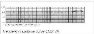

line
Frequency response curve CCM 25 | Frequency | Value | | :--- | :--- | | 20.10 | 10 | | 20.22 | 12 | | 20.34 | 14 | | 20.36 | 16 | | 20.38 | 18 | | 20.40 | 20 | | 20.42 | 22 | | 20.44 | 24 | | 20.46 | 26 | | 20.48 | 28 | | 20.50 | 30 | | 20.52 | 32 | | 20.54 | 34 | | 20.56 | 36 | | 20.58 | 38 | | 20.60 | 40 | | 20.62 | 42 | | 20.64 | 44 | | 20.66 | 46 | | 20.68 | 48 | | 20.70 | 50 | | 20.72 | 52 | | 20.74 | 54 | | 20.76 | 56 | | 20.78 | 58 | | 20.80 | 60 | | 20.82 | 62 | | 20.84 | 64 | | 20.86 | 66 | | 20.88 | 68 | | 20.90 | 70 | | 20.92 | 72 | | 20.94 | 74 | | 20.96 | 76 | | 20.98 | 78 | | 21.00 | 80 | | 21.02 | 82 | | 21.04 | 84 | | 21.06 | 86 | | 21.08 | 88 | | 21.10 | 90 | | 21.12 | 92 | | 21.14 | 94 | | 21.16 | 96 | | 21.18 | 98 | | 21.20 | 100 | | 21.22 | 102 | | 21.24 | 104 | | 21.26 | 106 | | 21.28 | 108 | | 21.30 | 110 | | 21.32 | 112 | | 21.34 | 114 | | 21.36 | 116 | | 21.38 | 118 | | 21.40 | 120 | | 21.42 | 122 | | 21.44 | 124 | | 21.46 | 126 | | 21.48 | 128 | | 21.50 | 130 | | 21.52 | 132 | | 21.54 | 134 | | 21.56 | 136 | | 21.58 | 138 | | 21.60 | 140 | | 21.62 | 142 | | 21.64 | 144 | | 21.66 | 146 | | 21.68 | 148 | | 21.70 | 150 | | 21.72 | 152 | | 21.74 | 154 | | 21.76 | 156 | | 21.78 | 158 | | 21.80 | 160 | | 21.82 | 162 | | 21.84 | 164 | | 21.86 | 166 | | 21.88 | 168 | | 21.90 | 170 | | 21.92 | 172 | | 21.94 | 174 | | 21.96 | 176 | | 21.98 | 178 | | 22.00 | 180 | | - - - - - - - - - - - - - - - - - - - - - - - - - - - - - - - - - - - - - - - - - - - - - - - - - - - - - - - - - - - - - - - - - - - - - - - - - - - - - - - - - - - - - - - - - - - - - - - - - - - -
line
| Frequency | Value | | --------- | ----- | | 21 | -12 | | 51 | -10 | | 100 | -8 | | 150 | -6 | | 200 | -4 | | 250 | -2 | | 300 | 0 | | 350 | 2 | | 400 | 4 | | 450 | 6 | | 500 | 8 | | 550 | 10 | | 600 | 12 | | 650 | 14 | | 700 | 16 | | 750 | 18 | | 800 | 20 | | 850 | 22 | | 900 | 24 | | 950 | 26 | | 1000 | 28 | | 1050 | 30 | | 1100 | 32 | | 1150 | 34 | | 1200 | 36 | | 1250 | 38 | | 1300 | 40 | | 1350 | 42 | | 1400 | 44 | | 1450 | 46 | | 1500 | 48 | | 1550 | 50 | | 1600 | 52 | | 1650 | 54 | | 1700 | 56 | | 1750 | 58 | | 1800 | 60 | | 1850 | 62 | | 1900 | 64 | | 1950 | 66 | | 2000 | 68 | | 2050 | 70 | | 2100 | 72 | | 2150 | 74 | | 2200 | 76 | | 2250 | 78 | | 2300 | 80 | | 2350 | 82 | | 2400 | 84 | | 2450 | 86 | | 2500 | 88 | | 2550 | 90 | | 2600 | 92 | | 2650 | 94 | | 2700 | 96 | | 2750 | 98 | | 2800 | 100 | | 2850 | 102 | | 2900 | 104 | | 2950 | 106 | | 3000 | 108 | | 3050 | 110 | | 3100 | 112 | | 3150 | 114 | | 3200 | 116 | | 3250 | 118 | | 3300 | 120 | | 3350 | 122 | | 3400 | 124 | | 3450 | 126 | | 3500 | 128 | | 3550 | 130 | | 3600 | 132 | | 3650 | 134 | | 3700 | 136 | | 3750 | 138 | | 3800 | 140 | | 3850 | 142 | | 3900 | 144 | | 3950 | 146 | | 4000 | 148 | | 4050 | 150 | | 4100 | 152 | | 4150 | 154 | | 4200 | 156 | | 4250 | 158 | | 4300 | 160 | | 4350 | 162 | | 4400 | 164 | | 4450 | 166 | | 4500 | 168 | | 4550 | 170 | | 4600 | 172 | | 4650 | 174 | | 4700 | 176 | | 4750 | 178 | | 4800 | 180 | | 4850 | 182 | | 4900 | 184 | | 4950 | 186 | | 5000 | 188 | | 5050 | 190 | | 5100 | 192 | | 5150 | 194 | | 5200 | 196 | | 5250 | 198 | | 5300 | 200 | | 5350 | 202 | | 5400 | 204 | | 5450 | 206 | | 5500 | 208 | | 5550 | 210 | | 5600 | 212 | | 5650 | 214 | | 5700 | 216 | | 5750 | 218 | | 5800 | 220 | | 5850 | 222 | | 5900 | 224 | | 5950 | 226 | | 6000 | 228 | | 6050 | 230 | | 6100 | 232 | | 6150 | 234 | | 6200 | 236 | | 6250 | 238 | | 6300 | 240 | | 6350 | 242 | | 6400 | 244 | | 6450 | 246 | | 6500 | 248 | | 6550 | 250 | | 6600 | 252 | | 6650 | 254 | | 6700 | 256 | | 6750 | 258 | | 6800 | 260 | | 6850 | 262 | | 6900 | 264 | | 6950 | 266 | | 7000 | 268 | | 7050 | 270 | | Note: The actual values may vary due to the random nature of the data generation. The provided values are just an example. The actual values may be the result of the formula being used in the code. There is no label for the data series. The values are estimated based on the formula input. The numbers in the data series are estimated based on the formula output.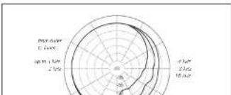
radar
| Angle | Value | |---|---| | 0° | 10 | | 45° | 15 | | 90° | 20 | | 135° | 25 | | 180° | 20 | | 225° | 15 | | 270° | 10 | | 315° | 5 | | 360° | 0 |Pressure-Gradient Transducers - Wide Cardioids
SCHOEPS
Mikrofone

CCM 21

CCM 21H
wide cardioids
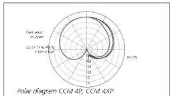
polar pattern very well maintained
throughout the frequency range
- a favorable compromise between omni (good low-frequency response) and cardioid (consistent directional pattern at all frequencies)
Uses:
CCM 21: often preferred for use as a spot microphone, or as the main pair for overall stereo pickup
CCM 21H: often preferred for use when recording vocals, acoustic guitar or percussion
CCM 22
"Open Cardioid" optimal combination of classic car- dioid directionality (CCM 4) with the sonic character of the wide car- dioid (CCM 21)
Frequency response curve CCM 21
Frequency response curve CCM 21H

radar
| Angle (°) | Polar Value | |-----------|-------------| | 0 | 0 | | 45 | 160 | | 90 | 360 | | 135 | 160 | | 180 | 0 | | 225 | -160 | | 270 | -360 | | 315 | -160 | | 360 | 0 |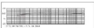
Frequency response curve CCM 22

Cardioids
SCHOEPS
Mikrofone

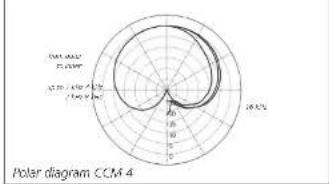
CCM 4
standard cardoid with clear sound quality, free of coloration
- all-purpose microphone for music and speech
– highly consistent frequency response
- Our best-selling compact microphone type
– cardio-d pattern is maintained even at low frequencies
- 0° axis is at the tip of the micro- phone
Uses: often preferred for singing or speaking voices and most instruments; as a spot microphone for X/Y, ORTF and M/S stereo recording
COM 4V
- cardiod with mild high-frequency boost
- all-purpose microphone for music and speech
– highly consistent polar response: cardioid pattern is maintained at low and high frequencies
0^ axes is at the side of the micro-
Frequency response curve CCM 4
radar
| Angle | Polar Value | |---|---| | 0° | 1.8 | | 30° | 1.5 | | 60° | 1.2 | | 90° | 0.9 | | 120° | 0.6 | | 150° | 0.3 | | 180° | 0.1 | | 210° | -0.2 | | 240° | -0.5 | | 270° | -0.8 | | 300° | -1.1 | | 330° | -1.4 | | 360° | -1.7 |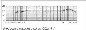

radar
| Angle | Value | |---|---| | 0 | 0 | | 45° | 25 | | 90° | 25 | | 135° | 25 | | 180° | 25 | | 225° | 25 | | 270° | 25 | | 315° | 25 | | 360° | 25 | | 405° | 25 | | 450° | 25 | | 505° | 25 | | 550° | 25 | | 605° | 25 | | 650° | 25 | | 705° | 25 | | 750° | 25 | | 805° | 25 | | 850° | 25 | | 905° | 25 | | 950° | 25 | | 1005° | 25 | | 1050° | 25 | | 1105° | 25 | | 1150° | 25 | | 1205° | 25 | | 1250° | 25 | | 1305° | 25 | | 1350° | 25 | | 1405° | 25 | | 1450° | 25 | | 1505° | 25 | | 1550° | 25 | | 1605° | 25 | | 1650° | 25 | | 1705° | 25 | | 1750° | 25 | | 1805° | 25 | | 1850° | 25 | | 1905° | 25 | | 2000° | 25 | | 2050° | 25 | | 2100° | 25 | | 2150° | 25 | | 2200° | 25 | | 2250° | 25 | | 2300° | 25 | | 2350° | 25 | | 2400° | 25 | | 2450° | 25 | | 2500° | 25 | | 2550° | 25 | | 2600° | 25 | | 2650° | 25 | | 2700° | 25 | | 2750° | 25 | | 2800° | 25 | | 2850° | 25 | | 2900° | 25 | | 2950° | 25 | | 3000° | 25 | | 3050° | 25 | | 3100° | 25 | | 3150° | 25 | | 3200° | 25 | | 3250° | 25 | | 3300° | 25 | | 3350° | 25 | | 3400° | 25 | | 3450° | 25 | | 3500° | 25 | | Note: The last row is a duplicate label (not explicitly labeled in the image). The previous row contains repeated 'in' values for the last row. The last row's 'in' value is repeated twice times the previous row's 'in'.Supercardioids
SCHOEPS
Mikrofone

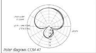
CCM 41
- all-purpose microphone for speech and music recording of all kinds
- well suited for use as the main microphones for stereo pickup
and/or as "spot" microphones - extended, smooth, well-balanced frequency response - often used for film and video sound
- where it can be used, it has distinct sonic and practical advantages over most shotgun microphones
- highly consistent polar response
- 0^ axis is at the microphone's tip
Uses: often preferred for use in film sound recording and as a spot microphone in orchestras
Frequency response curve CCM 41
radar
| Angle | Polar Value (degrees) | |---|---| | 0 | 0 | | 90 | 1.25 | | 180 | 0.75 | | 360 | 1.15 |
CCM 41V
- all-purpose microphone for music and speech; same uses and advantages as the CCM 41 - lateral pickup
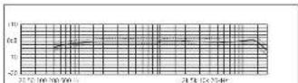
Frequency response curve CCM 41V
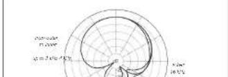
Figure-8
SCHOEPS
Mikrofone

CCM8
- figure-8 ("bid recliona") pattern
– clear sound quality, free of coloration - microphone for M/S and Blumen
Stereo
– highly consistent frequency and polar response - response essentially free of off-axis peaks like a good ribbon microphone (but not as delicate physically)
- lateral pickup
Uses: optimal for M/S and Blumlein stereo recording

Switchable Microphone
SCHOEPS
Mikrofone

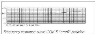
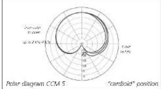
CCM 5
- mechanically switchable single-diaphragm microphone (omniV cardiod)
- smoother, more extended high-frequency response than most other multi-pattern microphones (e.g. dual-diaphragm microphones of other manufacturers)
- slightly brighter than the CCM 2H (omni) or CCM 4 (cardiod)
- a pure pressure transducer when in the "omni" setting (flat, extended low-frequency response without proximity effect or undue sensitivity to wind or solid-borne sound)
Uses:
preferred uses similar to those of the CCM 2 or CCM 2S and the CCM 4. In the cardiod setting: for use with singing or speaking voices or most instruments, as a spot micro phone, and for stereo recording with coincident, ORTF or MS microphone arrangements.
In the omnidirectional setting: for recording instruments, singers, etc. at relatively close range
line
| Frequency response curve CCM 5 "omni" position | | --------------------------------------------- | | -10 |
radar
| Angle (°) | Distance (m) | |-----------|--------------| | 0 | 1.4 | | 45 | 1.4 | | 90 | 1.4 | | 135 | 1.4 | | 180 | 1.4 | | 225 | 1.4 | | 270 | 1.4 | | 315 | 1.4 | | 360 | 1.4 |
Frequency response curve CCM 5 "cardioid" position
radar
| Angle (°) | Cardiol Position | |-----------|------------------| | 0 | 0 | | 45 | 10 | | 90 | 20 | | 135 | 10 | | 180 | 0 | | 225 | 10 | | 270 | 20 | | 315 | 10 | | 360 | 0 | | 405 | 10 | | 450 | 20 | | 505 | 10 | | 550 | 0 | | 605 | 10 | | 650 | 20 | | 705 | 10 | | 750 | 0 | | 805 | 10 | | 850 | 20 | | 905 | 10 | | 950 | 0 | | 1000 | 10 | | 1055 | 20 | | 1100 | 10 | | 1155 | 0 | | 1200 | 10 | | 1255 | 20 | | 1300 | 10 | | 1355 | 0 | | 1400 | 10 | | 1455 | 20 | | 1500 | 10 | | 1555 | 0 | | 1600 | 10 | | 1655 | 20 | | 1700 | 10 | | 1755 | 0 | | 1800 | 10 | | 1855 | 20 | | 1900 | 10 | | 1955 | 0 | | 2000 | 10 | | 2055 | 20 | | 2100 | 10 | | 2155 | 0 | | 2200 | 10 | | 2255 | 20 | | 2300 | 10 | | 2355 | 0 | | 2400 | 10 | | 2455 | 20 | | 2500 | 10 | | 2555 | 0 | | 2600 | 10 | | 2655 | 20 | | 2700 | 10 | | 2755 | 0 | | 2800 | 10 | | 2855 | 20 | | 2900 | 10 | | 2955 | 0 | | 3000 | 10 | | Note: The angle values are in degrees (from -95° to +95°). The 'cardiol position' is labeled on the chart.Microphones for Close Pickup
SCHOEPS
Mikrofone

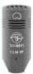
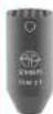
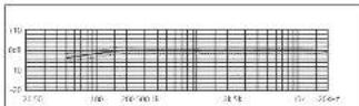
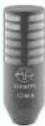
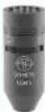
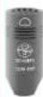
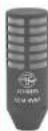
CCM 4P

CCM 4VP
CCM 4XP

CCM 4VXP
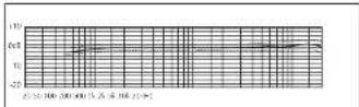
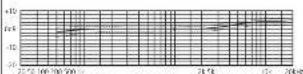
These microphones are tailored for people speaking in loud environments, an application primarily all about speech intelligibility. They are therefore used in close proximity and lower frequencies are attenuated. This enables environmental noises to be faded out and compensates for the "proximity effect", avoiding the voice having a booming, artificial quality which would be tiring and reduce speech intelligibility.

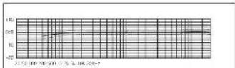
Low-frequency response curves of the two microphone types (P and XP) compared to the standard CGM 4 (measured at a 50 cm equivalent distance).
radar
| Angle (°) | Polar Value | |-----------|-------------| | 0 | 5 | | 360 | 18 | | 320 | 15 | | 280 | 12 | | 240 | 10 | | 200 | 8 | | 160 | 7 | | 120 | 6 | | 80 | 5 | | 40 | 4 | | 0 | 3 | | -40 | 2 | | -80 | 1 | | -120 | 1 | | -160 | 2 | | -200 | 3 | | -240 | 4 | | -280 | 5 | | -320 | 6 | | -360 | 7 | | -400 | 8 | | -440 | 9 | | -480 | 10 | | -520 | 11 | | -560 | 12 | | -600 | 13 | | -640 | 14 | | -680 | 15 | | -720 | 16 | | -760 | 17 | | -800 | 18 | | -840 | 17 | | -880 | 16 | | -920 | 15 | | -960 | 14 | | -1000 | 13 | | -1040 | 12 | | -1080 | 11 | | -1120 | 10 | | -1160 | 9 | | -1200 | 8 | | -1240 | 7 | | -1280 | 6 | | -1320 | 5 | | -1360 | 4 | | -1400 | 3 | | -1440 | 2 | | -1480 | 1 | | -1520 | 1 | | -1560 | 2 | | -1600 | 3 | | -1640 | 4 | | -1680 | 5 | | -1720 | 6 | | -1760 | 7 | | -1800 | 8 | | -1840 | 9 | | -1880 | 10 | | -1920 | 11 | | -1960 | 12 | | -2000 | 13 | | -2040 | 14 | | -2080 | 15 | | -2120 | 16 | | -2160 | 17 | | -2200 | 18 | | -2240 | 17 | | -2280 | 16 | | -2320 | 15 | | -2360 | 14 | | -2400 | 13 | | -2440 | 12 | | -2480 | 11 | | -2520 | 10 | | -2560 | 9 | | -2600 | 8 | | -2640 | 7 | | -2680 | 6 | | -2720 | 5 | | -2760 | 4 | | -2800 | 3 | | -2840 | 2 | | -2880 | 1 | | -2920 | 1 | | -2960 | 2 | | -3000 | 3 | | -3040 | 4 | | -3080 | 5 | | -3120 | 6 | | -3160 | 7 | | -3200 | 8 | | -3240 | 9 | | -3280 | 10 | | -3320 | 11 | | -3360 | 12 | | -3400 | 13 | | -3440 | 14 | | -3480 | 15 | | -3520 | 16 | | -3560 | 17 | | -3600 | 18 |
radar
| Angle (°) | Polar Value | |-----------|-------------| | 0 | 0 | | 90 | 18.5 | | 180 | 0 | | 270 | 18.5 | | 360 | 0 |Microphones for Close Pickup
SCHOEPS
Mikrofone


CCM AP
-cardioid pattern
for pickup of speech or music at close range
(under 20 cm)
– moderate attenuation of low frequencies
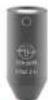
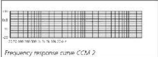
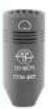
CCM 4VP
- cardioid pattern, side-adressed
- for pickup of speech or music at close range (under 20 cm), otherwise the sound may become "thin"
- moderate low frequency attenuation
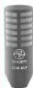
CCM 4XP
cardioid pattern
- for pickup of speech or music at close
range (under 10cm)
- considerable attenuation of low frequencies
CCM 4VXP
- cardioid for lateral
pickup - for pick up of speech or music at close
range (under 10 cm) - considerable attenuation of low frequencies

line
| Frequency response curve CCM 40 | Value | | ------------------------------- | ----- | | 0 | 0.5 | | 10 | 0.7 | | 20 | 0.8 | | 30 | 0.9 | | 40 | 1.0 | | 50 | 0.95 | | 60 | 0.9 | | 70 | 0.85 | | 80 | 0.8 | | 90 | 0.75 | | 100 | 0.7 | | 110 | 0.65 | | 120 | 0.6 | | 130 | 0.55 | | 140 | 0.5 | | 150 | 0.45 | | 160 | 0.4 | | 170 | 0.35 | | 180 | 0.3 | | 190 | 0.25 | | 200 | 0.2 |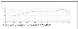
line
| Frequency response curve CCM 4VP | Value | | --------------------------------- | ----- | | 0 | -5 | | 10 | -3 | | 20 | -2 | | 30 | -1 | | 40 | 0 | | 50 | 1 | | 60 | 2 | | 70 | 3 | | 80 | 4 | | 90 | 3 | | 100 | 2 | | 110 | 1 | | 120 | 0 |
line
| Frequency response curve CCM 4XP | Value | | -------------------------------- | ----- | | 0 | 0 | | 10 | 1 | | 20 | 2 | | 30 | 3 | | 40 | 4 | | 50 | 5 | | 60 | 4 | | 70 | 3 | | 80 | 2 | | 90 | 1 | | 100 | 0 |
line
| Frequency response curve CCM 4VXP | Value | | --------------------------------- | ----- | | 0 | 0 | | 1 | 1 | | 2 | 2 | | 3 | 3 | | 4 | 4 | | 5 | 5 | | 6 | 4 | | 7 | 3 | | 8 | 2 | | 9 | 1 | | 10 | 0 |Acoustical Specifications of Compact Microphones
SCHOEPS
Mikrofone

| microphones type | Cost frequency pattern | pensitivity of evaluation range | CCR | ratio level | cal-to-noise max. SP ratio | I/O | 20% CI A-weighted | |
| CCM 2 cm/20 Hz | ≤ - 20 h ≤ - 16 mV/Hz | 23 dB | 1 dB | 83 dB | 150 dB | |||
| CCM 2H cm/20 Hz | ≤ - 20 h ≤ - 215 mV/Hz | 23 dB | 1 dB | 83 dB | 150 dB | |||
| CCM 2S cm/20 Hz | 70 Hz | 20 dB~17 mV/Hz | 24 dB | 12 dB | 87 dB~133 dB | |||
| CCM 2X3 | cm/20 Hz | 20 dB~15 mV/Hz | 26 dB | 14 dB | 80 dB~134 dB | |||
| CCM 2T | wide cardiox | 30 Hz~20 Hz | 13 mV/Hz | 24 dB | 14 dB | 80 dB | 132 dB | |
| CCM 2TH | wide cardiox | 20 Hz~20 Hz | 12 mV/Hz | 26 dB | 16 dB | 78 dB | 124 dB | |
| CCM 2Z | Osm Cardiox | 40 Hz~20 Hz | 14 mV/Hz | 23 dB | 14 dB | 80 dB | 131 dB | |
| CCM 4 cardiox | 40 Hz~70 Hz~13 mV/Hz | 24 dB~15 dB | 79 dB | 132 dB | ||||
| CCM 4V | cardiox | 40 Hz~20 Hz~ | 13 mV/Hz | 24 dB | 14 dB | 80 dB | 132 dB | |
| CCM 4I | supercardiox | 40 Hz~20 Hz~ | 14 mV/Hz | 24 dB | 15 dB | 79 dB | 132 dB | |
| CCM 4V | supercardiox | 40 Hz~20 Hz~ | 14 mV/Hz | 23 dB | 14 dB | 80 dB | 132 dB | |
| CCM 8 | figure 8 | 40 Hz~16 Hz~ | 10 mV/Hz | 20 dB | 18 dB | 76 dB | 134 dB | |
| CCM 5 cm/20 Hz | ≤ - 20 h ≤ - 16 mV/Hz | 26 dB~14 dB | 80 dB~133 dB | |||||
| cardiox | 40 Hz~20 kHz | 13 mV/Hz | 24 dB | 15 dB | 79 dB | 132 dB | ||
| CCM 4P | cardiox | Close pickup | 13 mV/Hz | 24 dB | 15 dB | 79 dB | 132 dB | |
| CCM 4V* | cardiox | Close pickup | 13 mV/Hz | 24 dB | 15 dB | 79 dB | 132 dB | |
| CCM 4X* | cardiox | Close pickup | 12 mV/Hz | 25 dB | 15 dB | 79 dB | 132 dB | |
| CCM 4V*P | cardiox | Close pickup | 10 mV/Hz | 25 dB | 14 dB | 80 dB | 134 dB |
A note about signal-to-noise specifications for studio microphones. The standard method, which SCHOLPS follows, is really just an alternate way of stating a microphone's equivalent noise level. It is designed to allow comparison of noise floor levels for different microphones. Unlike the signal-to-noise specifications for other types of audio equipment, which give the ratio of a component's clipping point to its noise floor. There value does not indicate a
that reference level substantially. The signal-to-noise specifications of our microphones would be 35 to 40 dB greater if the "hi-fi" approach were used.
The use of "A" weighting when specifying the equivalent noise level of microphones is another frequently misunderstood aspect of the standards. "A" weighting yields a distinctly lower noise specification – mostly by 10 dB or more, and this figure of course becomes the
Care and Maintenance / Troubleshooting
SCHOEPS
Mikrofone

Care of Compact Condenser Micro phones
Please take care to avoid placing microphones in a dusty environment. Keep them in their cases (e.g. the wood carrying case they come with) when not in use, since any dust that gets inside the capsules can adversely affect their functioning. Dust can affect the microphones in the following way: In combination with humidity it can lead to condensation and thus popping and cracking noises (often described as "frying sounds").
What to do if...
the microphone is noisy (clicks and pops) in high humidity?
If the microphone is brought in from the cold outdoors to a warm (and humid) environment, snapping or clicking noises can result from the condensation of moisture.
In this event, the microphone should be given between 30 and 60 minutes to warm up, and will then generally perform flawlessly.
If this treatment does not eliminate the noise, it is possible that dirt has gotten inside the transducer (capsule) itself – in which case the microphone must be sent back to the factory for cleaning. We strongly advise customers not to open a microphone or attempt to clean it themselves. Doing so would also invalidate all warranties.
Windscreens are recommended when microphones have to be used in dirty or dusty environments in order to avoid problems of the kind described above.
Troubleshooting
Wind noise and polar pattern
Noise problems can be taken into account when choosing a microphone pattern (directional)
SCH0EPS omnidirectional microphones are pressure transducers, as is our switchable-pattern compact microphone CCM 5 in its omnidirectional setting. If strong wind or physical vibration of the microphone is anticipated, a pressure transducer such as the CCM 2 S should be used instead of a cardioid or supercardioid. The distance between the microphone and the sound source should then be halved if possible.
Wind noise and windscreens
Air motion (wind, vocal "pooping" on sung or spoken consonants, motion of the microphone on a boom arm, or air currents due to heating or air conditioning systems) can cause noise that should always be dealt with. Even if it doesn't cause overload, it will detract from the clarity of sound. A wind or pop screen should be used, but should be chosen carefully to avoid changing the microphone's characteristics too much. Many screen types which are effective at reducing wind noise also have a tendency to reduce a microphone's directionality and/or its high-frequency response. Basket-type windscreens mainly cause some unevenness in the frequency response (see our general catalog for details).
Vibration
If noise from mechanical vibration enters a stand- or boom-mounted microphone, a shock mount (elastic suspension) should be used, and a loop of slack cable isolated and tied off so that it does not become another way for vibrations to reach the microphone. Unlike a wind screen, a shock mount will not affect the characteristics of a microphone. In many kinds of work it is well justified to use a shock mount "by default."
Overload
If transient or continual overload occurs, or seems likely to occur, it is useful to think of the complete set of equipment used for a record
Troubleshooting
SCHOEPS
Mikrofane

least two stages – the capsule and the amplifier. The only sound pressure that could overload a SCHOLPS microphone capsule (150+ db SPL) would also damage human hearing almost instantly, in practice our capsules are rarely over loaded except by explosions or direct exposure to strong wind. As a rule such overload will not damage the microphone, even strong wind blowing directly against the capsule membrane will not harm it unless the forces involved are rather enormous.
The input of the amplifier stage of a SCH0EPS CCM microphone can be overloaded, but only by sound pressure levels in excess of 130 dB. With a properly powered SCH0EPS microphone that is not being exposed to wind, any overloads will occur far more often in a mixer or preamp's input circuit than in the microphone itself. This is particularly true with equipment that was designed primarily for use with dynamic or consumer-type microphones. Thus if distortion is heard when wind, etc, is not the obvious cause, one of the first tests might be to plug in a balanced "pad" (resistive attenuator such as the SCH0EPS MDZ 10 or MDZ 20) at the console or preamp input to see whether that solves the problem. This type of pad is superior to built-in pad switches.
Unfortunately, even with fully professional equipment, "overload" indicators cannot always be relied upon to indicate input overload – many such indicators are wired only to later stages in the orcuity.
If a preamp or mixer has an input sensitivity control, it should be set for a good compromise between avoiding input overload on the one hand (sensitivity too high) and avoiding noise on the other (sensitivity too low). Ideally a mixer or preamp should not add any noise of its own to a microphone's signals, but a dB or two of hiss is better than gross distortion caused by clipping.
Low-frequency disturbances such as wind or vibration may not be perceived directly.
output of the microphone cable and the phantom-powered input of a mixer, preamp or recorder, thus protecting that input from overload.
Overload which does not otherwise seem to make sense may actually be a symptom of incorrect or inadequate microphone powering. Powering systems and their requirements are discussed near the beginning of this User Guide on page 5.
The most appropriate and most helpful trouble-shooting tools are:
- a well-known good microphone cable - a simple pop screen such as the SCHOEPS B 5 (or for outdoor recording, a wind screen such as the SCHOEPS W 5) - a balanced, in-line resistive attenuator ("pad") such as the SCHOEPS MDZ 10 or MDZ 20 - an ordinary multimeter
Warranty/ Declaration of Conformity - CE-Mark
SCHOEPS
Mikrofane

Warranty
We guarantee our products for a period of twenty-four months, excluding batteries. The guarantee period begins on the date of purchase.
Please provide your bill of sale in all cases as proof of guarantee; without it, repairs will be undertaken only at the owner's expense. We reserve the right to satisfy all warranty requirements regarding defects of workmanship or materials by means of repair or partial or complete replacement of the product, at our sale discretion.
Excluded from this guarantee are defects due to misuse (e.g. incorrect operation; mechanical damage), abuse or "acts of God." This guarantee is nullified in the event of jampering by unauthorized persons or agencies.
To secure your rights under this guarantee, send the product with proof of purchase and a precise description of the malfunction, at your expense, either to SCHOEPS (if you are a customer in Germany), or to our representative (if you are a customer outside Germany).
Prior to sending your defective product for repair, please contact your local dealer or distributor for instructions. In exceptional cases you can, by prior arrangement with SCHOPS, send the product directly to us from a foreign country. However any return shipment must then be prepaid; this tends to cause delays, especially for non-warranty service. Full payment must be made before a repaired item can be returned to the customer.
This guarantee does not affect any contractual agreements which may exist between the buyer and seller of the equipment.
This guarantee is world-wide.
Declaration of Conformity - CE-Mark
The CE-mark guarantees that all products conform to relevant standards approved by the European Community. The products described in this User Guide comply with current, relevant standards when used with cables from SCH0EPS.
Relevant directives:
EMC Directive 2014/30/EU
Relevant standards:
EN 55 103-1, -2 and those referred to by
them.
For your notes
SCHOEPS
Mikrofane

Errors and omissions excepted.
160203
SCHOEPS GmbH
Spitalstrabe 20
D-76227 Karlsruhe (Durlach)