PO-55H - Monitor AG Neovo - Free user manual and instructions
Find the device manual for free PO-55H AG Neovo in PDF.

User questions about PO-55H AG Neovo
0 question about this device. Answer the ones you know or ask your own.
Ask a new question about this device
Download the instructions for your Monitor in PDF format for free! Find your manual PO-55H - AG Neovo and take your electronic device back in hand. On this page are published all the documents necessary for the use of your device. PO-55H by AG Neovo.
USER MANUAL PO-55H AG Neovo
natural_image
Abstract geometric pattern with diagonal black and white stripes (no text or symbols)
neovo
THE DISPLAY CHOICE OF PROFESSIONALS
TABLE OF CONTENTS
SAFETY INFORMATION .... 1
CE Declaration of Conformity....1
Polish Center for Testing and Certification Notice .... 1
Electric, Magnetic and Electromagnetic Fields ("EMF") 2
Information for U.K. only 2
North Europe (Nordic Countries) Information....4
End-of-Life Disposal 4
Waste Electrical and Electronie Equipment-WEEE 4
Turkey RoHS 5
Ukraine RoHS 5
PRECAUTIONS 6
Cautions When Setting Up....6
Cautions When Using....7
Cleaning and Maintenance....7
Notice for the LCD Display 8
CHAPTER 1: PRODUCT DESCRIPTION....9
1.1 Package Contents 9
1.2 Preparing for the Installation 10
1.3 Moving the Display....10
1.3.1 Unpacking the Display....10
1.3.2 Carrying the Display....11
1.3.3 Setting Down the Display 11
1.3.4 Placing the Display....11
1.4 Wall Mounting Installation....12
TABLE OF CONTENTS
2.3 Connecting External Equipment (Video Player) 23
2.3.1 Using HDMI Video Input 23
2.3.2 Using DP Video Input 24
2.4 Connecting Audio Equipment 24
2.4.1 Connecting an External Audio Device 24
CHAPTER 3: USING THE LCD DISPLAY....25
3.1 Turning on the Power 25
3.2 Selecting the Input Source Signal 25
3.3 Adjusting the Volume....26
3.4 Setting Up the IR Sensor....27
CHAPTER 4: ON SCREEN DISPLAY MENU....28
4.1 Using the OSD Menu 28
4.2 OSD Menu Tree 29
CHAPTER 5: ADJUSTING THE LCD DISPLAY .... 30
5.1 Luminance....30
5.2 Picture 31
5.3 Color 32
5.4 OSD Settings....33
5.5 Setup 34
CHAPTER 6: APPENDIX....35
6.1 Warning Messages....35
6.2 Supported Resolution....35
6.3 Cleaning 37
SAFETY INFORMATION
CE Declaration of Conformity
This device complies with the requirements set out in the Council Directive on the Approximation of the Laws of the Member States relating to Electromagnetic Compatibility (2014/30/EU), Low-voltage Directive (2014/35/EU), RoHS directive (2011/65/EU).
This product has been tested and found to comply with the harmonized standards for Information Technology Equipment, these harmonized standards published under Directives of Official Journal of the European Union.
Polish Center for Testing and Certification Notice
The equipment should draw power from a socket with an attached protection circuit (a three-prong socket). All equipment that works together (computer, display, printer, and so on) should have the same power supply source.
The phasing conductor of the room's electrical installation should have a reserve short-circuit protection device in the form of a fuse with a nominal value no larger than 16 amperes (A).
To completely switch off the equipment, the power supply cable must be removed from the power supply socket, which should be located near the equipment and easily accessible.
A protection mark "B" confirms that the equipment is in compliance with the protection usage requirements of standards PN-93/T-42107 and PN-89/E-06251.
Electric, Magnetic and Electromagnetic Fields ("EMF")
- We manufacture and sell many products targeted at consumers, which, like any electronic apparatus, in general have the ability to emit and receive electromagnetic signals.
- One of our leading Business Principles is to take all necessary health and safety measures for our products, to comply with all applicable legal requirements and to stay well within the EMF standards applicable at the time of producing the products.
- We are committed to develop, produce and market products that cause no adverse health effects.
- We confirm that if its products are handled properly for their intended use, they are safe to use according to scientific evidence available today.
- We play an active role in the development of international EMF and safety standards, enabling us to anticipate further developments in standardization for early integration in its products.
Information for U.K. only
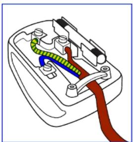
WARNING - THIS APPLIANCE MUST BE EARTHED.

SAFETY INFORMATION
If the fitted plug is not suitable for your socket outlets, it should be cut off and an appropriate 3-pin plug fitted in its place.
If the mains plug contains a fuse, this should have a value of 5A. If a plug without a fuse is used, the fuse at the distribution board should not be greater than 5A.
natural_image
Diagram of a plug socket with colored wires and connectors (no text or labels)How to connect a plug
The wires in the mains lead are coloured in accordance with the following code:
BLUE - "NEUTRAL" ("N")
BROWN - "LIVE" ("L")
GREEN & YELLOW - "EARTH" ("E")
- The GREEN & YELLOW wire must be connected to the terminal in the plug which is marked with the letter "E" or by the Earth symbol or coloured GREEN or GREEN & YELLOW.
SAFETY INFORMATION
North Europe (Nordic Countries) Information
Placering/Ventilation
VARNING: FÖRSÄKRA DIG OM ATT HUVUDBRYTARE OCH UTTAG ÄR LÄTÄTKOMLIGA, NÄR DU STÄLLER DIN UTRUSTNING PÅPLATS.
Placering/Ventilation
ADVARSEL: S∅RG VED PLACERINGEN FOR, AT NETLEDNINGENS STIK OG STIKKONTAKT ER NEMT TILGÆNGELIGE.
Paikka/llmankierto
VAROITUS: SIJOITA LAITE SITEN, ETTÄ VERKKOJOHTO VOIDAAAN TARVITTAESSA HELPOSTI IRROTTAA PISTORASIASTA.
End-of-Life Disposal
Your new Public Information Display contains materials that can be recycled and reused. Specialized companies can recycle your product to increase the amount of reusable materials and to minimize the amount to be disposed of.
Please find out about the local regulations on how to dispose of your old display from your local dealer.
(For customers in Canada and U.S.A.)
SAFETY INFORMATION
End of Life Directives-Recycling

Your new Public Information Display contains several materials that can be recycled for new users.
Please dispose of according to all Local, State, and Federal laws.
Restriction on Hazardous Substances statement (India)
This product complies with the "India E-waste Rule 2011" and prohibits use of lead, mercury, hexavalent chromium, polybrominated biphenyls or polybrominated diphenyl ethers in concentrations exceeding 0.1 weight % and 0.01 weight % for cadmium, except for the exemptions set in Schedule 2 of the Rule.
E-Waste Declaration for India

This symbol on the product or on its packaging indicates that this product must not be disposed of with your other household waste. Instead it is your responsibility to dispose of your waste equipment by handing it over to a designated collection point for the recycling of waste electrical and electronic equipment. The separate collection and recycling of your waste equipment at the time of disposal will help to conserve natural resources and ensure that it is recycled in a manner that protects human health and the environment.
Batteries

For EU: The crossed-out wheeled bin implies that used batteries should not be put to the general household waste! There is a separate collection system for used batteries, to allow proper treatment and recycling in accordance with legislation.
Please contact your local authority for details on the collection and recycling schemes.
For Switzerland: The used battery is to be returned to the selling point.
PRECAUTIONS

CAUTION
RISK OF ELECTRIC SHOCK DO NOT OPEN

Symbols used in this manual
| This icon indicates the existence of a potential hazard that could result in personal injury or damage to the product. | |
| This icon indicates important operating and servicing information. |
Notice
- Read this User Manual carefully before using the LCD display and keep it for future reference.
- The product specifications and other information provided in this User Manual are for reference only. All information is subject to change without notice. Updated content can be downloaded from our web site at www.agneovo.com.
- To protect your rights as a consumer, do not remove any stickers from the LCD display. Doing so may affect the determination of the warranty period.
Cautions When Setting Up
- Do not place the LCD display near heat sources, such as a heater, exhaust vent, or in direct sunlight.
- Do not cover or block the ventilation holes in the housing.
PRECAUTIONS
Cautions When Using
- Use only the power cord supplied with the LCD display.
- The power outlet should be installed near the LCD display and be easily accessible.
- If an extension cord is used with the LCD display, ensure that the total current consumption plugged into the power outlet does not exceed the ampere rating.
- Do not allow anything to rest on the power cord. Do not place the LCD display where the power cord may be stepped on.
- If the LCD display will not be used for an indefinite period of time, unplug the power cord from the power outlet.
- To disconnect the power cord, grasp and pull by the plug head. Do not tug on the cord; doing so may cause fire or electric shock.
- Do not unplug or touch the power cord with wet hands.
- When turning off the display by detaching the power cord, wait 6 seconds before re-attaching the power cord for normal operation.
- Do not knock or drop the display during operation or transportation.
Cleaning and Maintenance
- To protect your display from possible damage, do not put excessive pressure on the LCD panel. When moving your

Warning:

Unplug the power cord from the power outlet and refer to qualified service
personnel under the following conditions:
- When the power cord is damaged.
- If the LCD display has been dropped or the housing has been damaged.
◆ If the LCD display emits smoke or a distinct odor.
PRECAUTIONS
Notice for the LCD Display
- In order to maintain the stable luminous performance, it is recommended to use low brightness setting.
- Due to the lifespan of the lamp, it is normal that the brightness quality of the LCD display may decrease with time.
- When static images are displayed for long periods of time, the image may cause an imprint on the LCD display. This is called image retention or burn-in.
◆ To prevent image retention, do any of the following:
- Set the LCD display to turn off after a few minutes of being idle.
- Use a screen saver that has moving graphics or a blank white image.
- Execute the ANTI-BURN-IN function of the LCD display. See "Anti-Burn-in" on page 31.
- Switch desktop backgrounds regularly.
- Adjust the LCD display to low brightness settings.
- Turn off the LCD display when the system is not in use.
◆ Things to do when the LCD display shows image retention:
- Turn off the LCD display for extended periods of time. It can be several hours or several days.
- Use a screen saver and run it for extended periods of time.
- Use a black and white image and run it for extended periods of time.
- There are millions of micro transistors inside the LCD display. It is normal for a few transistors to be damaged and to produce spots. This is acceptable and is not considered a failure.
- IMPORTANT: Always activate a moving screen saver program when you leave your display unattended. Always activate a periodic screen refresh application if the unit will display unchanging static content
1.1 Package Contents
When unpacking, check if the following items are included in the package. If any of them is missing or damaged, contact your dealer.
LCD Display
Quick start guide

Power cord (for EU except UK)
Remote control
Power cord (for UK)
Note:
◆ Remote control is shipped with the supplied AAA batteries.
For all other regions, apply a power cord that conforms to the AC voltage of the power socket and has been approved by and complies with the safety regulations of the particular
PRODUCT DESCRIPTION
1.2 Preparing for the Installation
- Due to the high power consumption, always use the plug exclusively designed for this product. If an extended line is required, please consult your service agent.
- The product should be installed on a flat surface to avoid tipping. The distance between the back of the product and the wall should be maintained for proper ventilation. Avoid installing the product in the kitchen, bathroom or any other places with high humidity so as not to shorten the service life of the electronic components.
- The product can normally operate only under 5000m in altitude. In installations at altitudes above 3000m, some abnormalities may be experienced.
1.3 Moving the Display
1.3.1 Unpacking the Display
Before unpacking the display, prepare a flat and stable surface near a wall outlet. Set the product box in an upright position according to the arrow markings on the outside of the product box.
1 Detach the four locks.
2 Open the product box from the top of the box.
3 Take the accessories out and remove the top cushion.
4 Hold the display by the carrying handles firmly with two people to remove the display from the box.

Warning:
Do not press too hard on the LCD panel or edge of the frame, as this may cause the device to malfunction.
During unpacking, make sure to hold the carrying handles to remove the device from its packaging.
PRODUCT DESCRIPTION
1.3.2 Carrying the Display
When carrying the display, always hold it with two people using both hands and the screen facing forward.
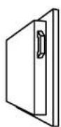


1.3.3 Setting Down the Display
When setting the display down, place the screen face down on a flat and stable surface covered by a protective sheet and a table cushion as shown in the illustration provided.
natural_image
3D diagram of a rectangular electronic component with internal components and mounting holes (no text or symbols)
Caution:
- Avoid applying force or using sharp objects on the LCD panel at all times.

Caution:
- Never press or place anything on the back cover. This may damage the internal parts of the display.
PRODUCT DESCRIPTION
1.4 Wall Mounting Installation
To mount this display to a wall, you will have to obtain a standard wall-mounting kit (commercially available). We recommend using a mounting interface that complies with TUV-GS and/or UL1678 standard in North America.
To wall-mount the LCD display, screw the mounting bracket to the VESA holes at the rear of the LCD display.
The IR and Light sensors are located on the right side of the rear of the display. Please reposition the IR and Light sensors to the desired location before mounting the display. Refer to P.27 for more information.

text_image
400mm U 400mm PO-55FNote:
- Avoid the wall-mounting kit to block the ventilation holes on the back of the display.
Make sure the distance between the LCD display fans and the wall is at least 4\~5 cm. - Secure the LCD display on a solid wall strong enough to bear its weight.
Lay a protective sheet on a table, which was wrapped around the display when it was packaged, beneath the screen surface so as not to scratch the screen face. - Ensure you have all accessories for mounting this display (wall mount, ceiling mount, etc).
Follow the instructions that come with the base mounting kit. Failure to follow correct mounting procedures could result in damage to the equipment or injury to the user or installer.
PRODUCT DESCRIPTION

Caution:
To prevent the display from falling:
For wall or ceiling installation, we recommend installing the display with metal brackets which are commercially available. For detailed installation instructions, refer to the guide received with the respective bracket.
To lessen the probability of injury and damage resulting from fall of the display in case of earthquake or other natural disaster, be sure to consult the bracket manufacturer for installation location.
1.4.2 Ventilation Requirements for Enclosure Locating
To allow heat to disperse, leave space between surrounding objects as shown in the diagram below.
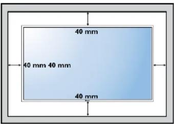
text_image
40 mm 40 mm 40 mm 40 mm1.5 Mounting in Portrait Position
This direction can be installed in the circuit.
PRODUCT DESCRIPTION
1.6 LCD Display Overview
1.6.1 Control Panel
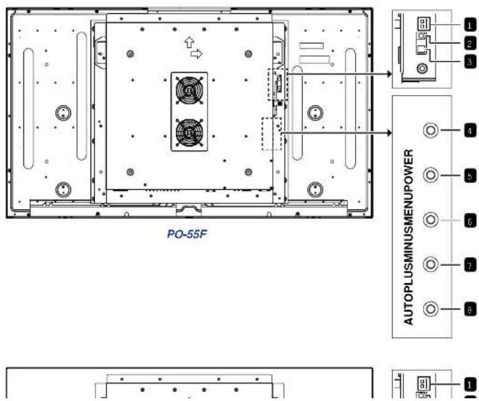
text_image
PO-55F AUTOPLUSMINUSMENUPower 1 2 3 4 5 6 7 8 9 10PRODUCT DESCRIPTION
1 IR sensor indicator
Displays the status of the IR sensor.
• Green: The display's power is on.
• Red: The display is in Stand-by mode.
- Off: The display's power is off.
2 IR sensor
Receives the signal from the remote control.
3 Light sensor
Receives ambient light and enable automatic backlight adjustment.
Note:
- Please make sure the light sensor is not covered when enabling Auto Dimming function.
4 POWER
Turns the power on/off.
Note:
- POWER button does not function if the Main Power switch is off.
5 MENU
- Displays the On Screen Display (OSD) menu.
- Selects items or accepts the settings made in the OSD menu.
6 MINUS
• Decreases the audio output level while OSD menu is off.
- Navigates through the OSD menu items.
• Decreases the adjustment while OSD menu is on.
7 PLUS
- Increases the audio output level while OSD menu is off.
- Navigates through the OSD menu items.
- Increases the adjustment while OSD menu is on.
8 AUTO
- Performs auto adjustment for the VGA input when the OSD menu is off.
- Exits the current menu when the OSD menu is on.
PRODUCT DESCRIPTION
1.6.2 Input/Output Terminals

text_image
RS232 USB AUDIO AUDIO OUT IN D-SUBHD/MIDVI 1.2 67 PO-55F DP 10
natural_image
Simple line drawing of a beam with supports and evenly spaced dots, no text or symbols presentPRODUCT DESCRIPTION

AC-IN
Connects with the supplied power cord.

Main Power switch
Switches the main power on or off.

RS232
Connects with the serial IO connector of another device.

USB
Reserved for the touch screen. Not supported with this model.

Audio out
- Outputs the audio that is supplied by the video source.
- Connects with an external audio amplifier, or other applicable audio devices.
Note:
◆ Headphones and earphones are not supported.

Audio in
Connects with the audio out connector of a video source such as a computer, video player when the display is connected to the source via the VGA or DVI connector.

D-SUB
Connects with the analog video output (VGA) of a computer.

HDMI
Connects with devices supporting audio/video data using the HDMI interface.

DVI
Connects with the digital video output of a computer, and other applicable devices.

DisplayPort (DP)
Connects with the digital video output of a computer, and other applicable devices.
PRODUCT DESCRIPTION
1.7 Remote Control
1.7.1 General Functions
1 [◀] POWER
Turns the display on or off.
Note:
If the power indicator is not lit then the controls will not function.
2 MENU
Displays the OSD menu. Please refer to page 28.
3 [◀] ▶ [ ]AVGATION buttons
Navigates through menus, selects items, and adjusts values.
4 EXIT
Exits the current menu.
5 ENTER
Selects items or accepts the settings made in the OSD menu.
6 SOURCE
Switches the video input source. Use the [▲] [▼ buttons to select [D-SUB], [DVI], [HDMI], or [DP] and press the ENTER button to confirm the selection.
7 [H]¥OL
- Press [ —] to decrease volume.
- Press 1 +1 to increase volume

text_image
POWER MUTE MENU II ■ ENTER F1 F2 F3 F4 PRLIO 1 2 3 18-548 MSLAIE 4 5 6 ZOOM OND 7 8 9 RHOUBUC 0 - + VOL SLOVE SHOW SOURCE EXIT ① ② ③ ④ ⑤ ⑥ ⑦PRODUCT DESCRIPTION
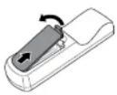
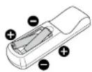
1.7.2 Inserting the Batteries in the Remote Control
The remote control is powered by two 1.5V AAA batteries.
To install or replace batteries:
1 Open the remote control battery compartment cover.
2 Align the batteries according to the (+) and (-) indications inside the battery compartment.
3 Replace the cover.

1.7.3 Handling the Remote Control
- Do not subject to strong shock.
- Do not allow water or other liquid to splash the remote control. If the remote control gets wet, wipe it dry immediately.
- Avoid exposure to heat and steam.
- Other than to install the batteries, do not open the remote control.
1.7.4 Operating Range of the Remote Control

Caution:
The incorrect use of batteries can result in leaks or bursting. Be sure to follow these instructions:
Place "AAA" batteries matching the (+) and (−) signs on each battery to the (+) and (−) signs of the battery compartment.
♦ Do not mix battery types.
Do not combine new batteries with used ones. It causes shorter life or leakage of batteries.
Remove the dead batteries immediately to prevent them from liquid leaking in the battery compartment. Don't touch exposed battery acid, as it can damage your skin.
Note:
◆ If you do not intend to use
CHAPTER 2: MAKING CONNECTIONS
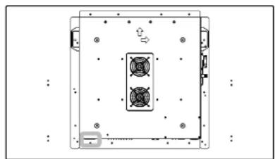
2.1 Connecting the Power
1 Connect one end of the power cord to the AC IN connector at the side of the LCD display.
2 Connect the other end of the power cord to a power outlet or a power supply.
3 Set the Main Power switch to ON.
natural_image
Top-down schematic of a device casing with internal components and mounting holes (no text or symbols)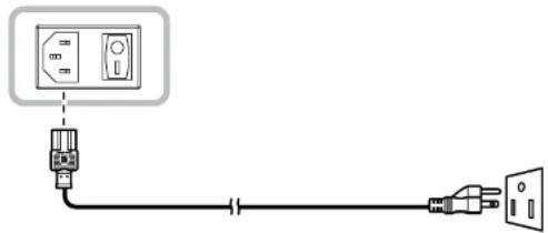
natural_image
Pure electrical circuit lines without any symbols
Caution:
MAKING CONNECTIONS
2.2 Connecting a Computer
2.2.1 Using D-SUB Input
1 Connect one end of a D-SUB cable to the D-SUB connector of the LCD display and the other end of a D-SUB cable to the VGA OUT (D-SUB) connector of the computer.
2 For audio input, connect one end of an audio cable to the AUDIO IN connector of the LCD display and the other end of an audio cable to the AUDIO OUT connector of the computer.
3 Press the SOURCE button on the remote control to select the video input source (D-SUB). Once selected, the audio input setting will automatically switch to the correct audio source for the video connection.

text_image
AUDIO IN D-SUB D-SUB VGA OUT D-SUB 15 pin AUDIO OUT ComputerMAKING CONNECTIONS
2.2.3 Using DVI Input
1 Connect one end of a DVI cable to the DVI connector of the LCD display and the other end of a DVI cable to the DVI OUT connector of the computer.
2 For audio input, connect one end of an audio cable to the AUDIO IN connector of the LCD display and the other end of an audio cable to the AUDIO OUT connector of the computer.
3 Press the SOURCE button on the remote control to select the video input source (DVI). Once selected, the audio input setting will automatically switch to the correct audio source for the video connection.

flowchart
graph TD
    A["AUDIO IN"] --> B["DVI"]
    B --> C["DVI OUT"]
    C --> D["Computer"]
2 2 4 Using RS232 Input
MAKING CONNECTIONS
2.2.5 Using DP Input
1 Connect one end of a DisplayPort cable to the DP connector of the LCD display and the other end of a DisplayPort cable to the DisplayPort connector of the computer.
2 Press the SOURCE button on the remote control to select the video input source (DP).
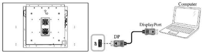
text_image
Diagram showing a device layout and connected to a computer via DP and DisplayPort components2.3 Connecting External Equipment (Video Player)
2.3.1 Using HDMI Video Input
Connect one end of an HDMI cable to the HDMI connector of the LCD display and the other end of an HDMI cable to the HDMI OUT connector of the video player.
MAKING CONNECTIONS
2.3.2 Using DP Video Input
Connect one end of a DisplayPort cable to the DP connector of the LCD display and the other end of a DisplayPort cable to the DisplayPort connector of the video player.
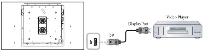
text_image
Diagram showing an electronic device connected to a video player via a display port, with labeled ports and ports.2.4 Connecting Audio Equipment
2.4.1 Connecting an External Audio Device
Connect one end of an audio cable to the AUDIO OUT connector of the LCD display and the other end of an audio cable to the AUDIO IN connector of the audio device.

CHAPTER 3: USING THE LCD DISPLAY
3.1 Turning on the Power
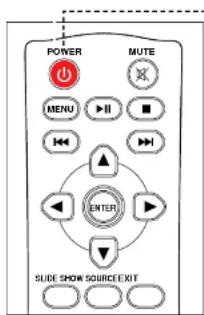
text_image
POWER MUTE MENU ENTER ENTER SLIDE SHOW SOURCE EXITPOWER button
1 Plug the power cord to a power outlet or power supply.
2 Set the Main Power switch to ON.
3 Press the ⏻ button to turn the LCD display on.
When the LCD display is turned on, press the ⏻ button to turn off the LCD display.
3.2 Selecting the Input Source Signal
Note:
The LCD display still consumes power as long as the power cord is connected to the power outlet. Disconnect the power cord to completely cut off power.
Note:
If no input source is detected, after pressing the SOURCE button, a menu with available input sources will be displayed on the screen.

USING THE LCD DISPLAY
3.3 Adjusting the Volume
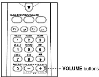
text_image
SLIDE SHOW SOURCE/EXIT F1 F2 F3 F4 PHOTO MUSE MUSE 1 2 3 16A10 ROTATE 4 5 6 200R GND 7 8 9 FILTER 0 - + + RCT VOLUME buttonsPress the -or button to adjust the volume.
Note:
- After pressing the—or + button, the volume adjustment bar is displayed on the screen automatically.

◆ Press the MUTE button to mute the audio.
USING THE LCD DISPLAY
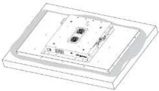
3.4 Setting Up the IR Sensor
Before using the remote control, the IR sensor must be positioned correctly. The IR sensor is located on the right side of the rear of the display as illustrated below.
To set up the IR sensor, do the following:
1 Remove the two screws securing the IR sensor to the LCD display and loosen the IR sensor.
2 Unthread the cables from the cable clip.
3 Attach the IR sensor to the desired position on the display using the magnets located on the sensor.
4 Point the remote control toward the display's IR sensor within a distance of less than 3 m / 9.84 ft, and a horizontal and vertical angle of less than 30 degrees, when operating the remote control.
Reverse steps 1 \~ 3 to return the sensor to its original position.

natural_image
Top-down schematic of a device casing with internal components and directional arrows (no text or symbols)
CHAPTER 4: ON SCREEN DISPLAY MENU
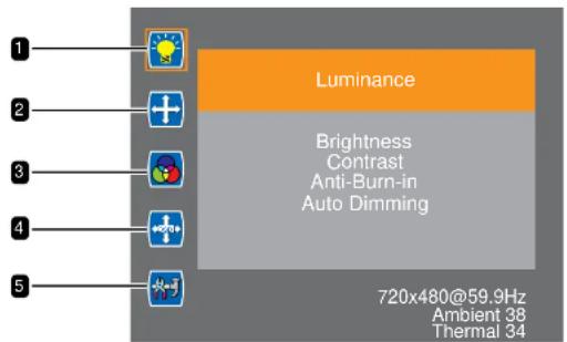
4.1 Using the OSD Menu
| # | Menu Navigation Control Panel Remote Control | ||
| 1 | Display the main menu screen. | Press theMENUbutton. | |
 | |||
| 2 | Enter the submenu. | 1 Press thePLUSorMINUButtonto select themain menu item.2 Press theMENUbutton to enterthe submenu. | 1 Press the▲or▼button to selectthe main menuitem.2 Press theENTERbutton to enterthe submenu. |
 | |||
| The item inside the orange rectangle indicates the activesubmenu item. | |||
| 3 | Adjust the settings.For example: | 1 Press thePLUSorMINUButtonto select thesubmenu item. | 1 Press the▲or▼button to selectthe submenuitem. |
 | |||
ON SCREEN DISPLAY MENU
Note:
◆ Availability of some menu items depend on the input source signal.
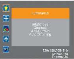
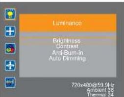
4.2 OSD Menu Tree
text_image
Luminance Brightness Contrast Anti-Burn-in Auto Dimming 720x480@59.9Hz Ambient 38 Thermal 34| Main Menu Submenu Remarks | ||
| 1. Luminance • Brightness | ContrastAnti-Burn-inAuto Dimming | See page 30. |
| 2. Picture • Phase | ClockH Position | See page 31. |
CHAPTER 5: ADJUSTING THE LCD DISPLAY
5.1 Luminance
Adjusts the LCD display's luminance settings.
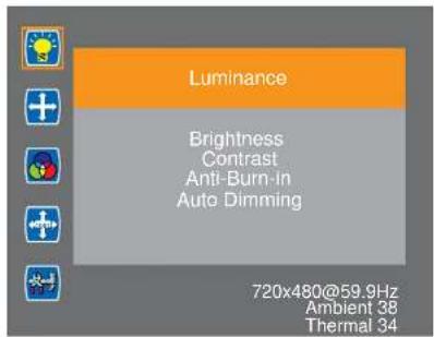
text_image
Luminance Brightness Contrast Anti-Burn-in Auto Dimming 720x480@59.9Hz Ambient 38 Thermal 341 Press the MENU button on the control panel or the remote control to call out the OSD window.
2 Select Luminance, then press the MENU button on the control panel or the ENTER button on the remote control.
3 Press the PLUS / MINUS button on the control panel or the ▲/▼button on the remote control to select an option.
4 Press the MENU button on the control panel or the ENTER button on the remote control to enter the adjustment mode.
| Item Function Operation Range | |||
| Brightness | Adjusts the brightness of the display. | Press the PLUS / MINUS button on the control panel or the ▲/▼ button on the remote control to adjust the value. | 0 to 100 |
Original Setting High Setting Low Setting   | |||
ADJUSTING THE LCD DISPLAY
| Item Function Operation Range | |||
| Anti-Burn-in | Triggers the screen saver function (Off/On). If set to On then a white rectangle will automatically go across the screen, and will be followed by a black rectangle. | Press the MENU button on the control panel or the ENTER button on the remote control to select the setting. | OffOn |
| Auto Dimming | Adjusts the backlight of the LCD automatically depending on the amount of ambient light.Note: Please make sure the light sensor is not covered when enabling Auto Dimming function. | OffOn | |
5.2 Picture
Adjusts the LCD display's image settings.
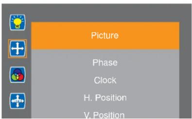
text_image
Picture Phase Clock H. Position V. Position1 Press the MENU button on the control panel or the remote control to call out the OSD window.
2 Select Picture, then press the MENU button on the control panel or the ENTER button on the remote control.
3 Press the PLUS / MINUS button on the control panel or the ▲/▼button on the remote control to select an option.
4 Press the MENU button on the control
ADJUSTING THE LCD DISPLAY
5.3 Color
Adjusts the LCD display's color settings.

text_image
Color Color Temperature Red Green Blue 720x480@59.9Hz Ambient 38 Thermal 341 Press the MENU button on the control panel or the remote control to call out the OSD window.
2 Select Color, then press the MENU button on the control panel or the ENTER button on the remote control.
3 Press the PLUS / MINUS button on the control panel or the ▲/▼button on the remote control to select an option.
4 Press the MENU button on the control panel or the ENTER button on the remote control to enter the adjustment mode.
| Item Function Operation Range | |||
| Color Temperature | Adjusts the color temperature of the display. | Press the PLUS / MINUS button on the control panel or the ▲/▼ button on the remote control to select the setting. | 6500K9300K11500KsRGBUser Define |
| Red | Adjusts the red color.Note: This item becomes available if you set the Color Temperature to | 0 to 100 | |
ADJUSTING THE LCD DISPLAY
5.4 OSD Settings
Adjusts the OSD settings.
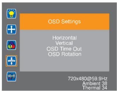
text_image
OSD Settings Horizontal Vertical OSD Time Out OSD Rotation 720x480@59.9Hz Ambient 38 Thermal 341 Press the MENU button on the control panel or the remote control to call out the OSD window.
2 Select OSD Settings, then press the MENU button on the control panel or the ENTER button on the remote control.
3 Press the PLUS / MINUS button on the control panel or the ▲/▼button on the remote control to select an option.
4 Press the MENU button on the control panel or the ENTER button on the remote control to confirm the selection.
| Item Function Operation Range | |||
| Horizontal | Moves the position of the OSD menu horizontally. | Press the PLUS / MINUS button on the control panel or the ▲/▼ button on the remote control to adjust the value. | 0 to 100 |
| Vertical | Moves the position of the OSD menu vertically. | 0 to 100 | |
ADJUSTING THE LCD DISPLAY
5.5 Setup
Configure the setup settings.
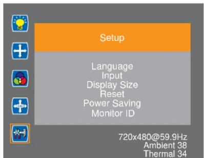
text_image
Setup Language Input Display Size Reset Power Saving Monitor ID 720x480@59.9Hz Ambient 38 Thermal 341 Press the MENU button on the control panel or the remote control to call out the OSD window.
2 Select Setup, then press the MENU button on the control panel or the ENTER button on the remote control.
3 Press the PLUS / MINUS button on the control panel or the ▲/▼button on the remote control to select an option.
4 Press the MENU button on the control panel or the ENTER button on the remote control to enter the adjustment mode.
| Item Function Operation Range | |||
| Language Chooses the OSD menu language. | English | ||
| Input | Switches the input source when multiple sources are connected. | D-SUB | |
| DVI | |||
| HDMI | |||
| DP | |||
CHAPTER 6: APPENDIX
6.1 Warning Messages
| Warning Messages Cause Solution | ||
| ATTENTIONCANNOT DISPLAY THIS VIDEO | The resolution or the refresh rate of the graphics card of the computer is set too high. | · Change the resolution or the refresh rate of the graphics card. |
| ATTENTIONNO VIDEO INPUT | The LCD display cannot detect the input source signal. | · Check if the input source is turned on.· Check if the signal cable is properly connected.· Check if any pin inside the cable connector is twisted or broken. |
6.2 Supported Resolution
VGA Resolution:
| Resolution Refresh Rate (Hz) | Horizontal Frequency (KHz) | Pixel Frequency (MHz) | Standard Type | |
| 640x480 | 60 31.5 25.175 Industrial Standard | |||
| 75 37.5 31.5 VESA Standard | ||||
| 60 37.9 40 VESA Guideline | ||||
APPENDIX
DVI Resolution:
| Resolution Refresh Rate (Hz) | Horizontal Frequency (KHz) | Pixel Frequency (MHz) | Standard Type | |
| 640x480 | 60 31.5 25.175 | Industrial Standard | ||
| 75 37.5 31.5 | ||||
| 1280x1024 60 64 | 108 | |||
| 1920x1080 60 67 | 5 148.5 | |||
HDMI Resolution:
| Resolution Refresh Rate (Hz) | Horizontal Frequency (KHz) | Pixel Frequency (MHz) | Standard Type |
| 1920x1080 60 67.5 148.5 |
General guidelines:
- The PC text quality is optimum in HD 1080 mode (1920x1080, 60Hz).
- Your PC display screen might appear different depending on the manufacturer (and your particular version of Windows).
- Check your PC instruction book for information about connecting your PC to a display.
- When horizontal synchronous signals seem irregular in RGB mode, check PC power saving mode or cable connections.
- The display settings table complies to the IBM/VESA standards, and based on the analog input.
- The DVI support mode is regarded as same to the PC support mode.
- The best timing for the vertical frequency to each mode is 60Hz.
APPENDIX
6.3 Cleaning
Caution When Using the Display
- Do not bring your hands, face or objects close to the ventilation holes of the display. The top of the display is usually very hot due to the high temperature of exhaust air being released through the ventilation holes. Burns or personal injuries may occur if any body parts are brought too close. Placing any object near the top of the display could also result in heat related damage to the object as well as the display itself.
- Be sure to disconnect all cables before moving the display. Moving the display with its cables attached may damage the cables and thus cause fire or electric shock.
- Disconnect the power plug from the wall outlet as a safety precaution before carrying out any type of cleaning or maintenance procedure.
Front Panel Cleaning Instructions
- The front of the display has been specially treated. Wipe the surface gently using only a cleaning cloth or a soft, lint-free cloth.
- If the surface becomes dirty, soak a soft, lint-free cloth in a mild detergent solution. Wring the cloth to remove excess liquid. Wipe the surface of the display to remove dirt. Then use a dry cloth of the same type to dry.
- Do not scratch or hit the surface of the panel with fingers or hard objects of any kind.
- Do not use volatile substances such as insert sprays, solvents and thinners.
Cabinet Cleaning Instructions
- If the cabinet becomes dirty, wipe the cabinet with a soft, dry cloth.
- If the cabinet is extremely dirty, soak a lint-free cloth in a mild detergent solution. Wring the cloth to remove as much moisture as possible. Wipe the cabinet. Use another dry cloth to wipe over until the surface is dry.
- Do not allow any water or detergent to come into contact with the surface of the display. If water or moisture gets inside the unit, operating problems, electrical and shock hazards may result.
APPENDIX
6.4 Troubleshooting
| Symptom Possible Cause Remedy | ||
| No picture is displayed • The main power switch on the side of the display is not switched on.• The selected input has no connection.• The display is in standby mode. | 1 Plug in the power cord.2 Make sure the Main Power switch is switched on.3 Connect a signal connection to the display. | |
| Interference displayed on the display or audible noise is heard | Caused by surrounding electrical appliances or fluorescent lights. | Move the display to another location to see is the interference is reduced. |
| Color is abnormal The signal cable is not connected properly. | Make sure that the signal cable is attached firmly to the bottom of the display. | |
| Picture is distorted with abnormal patterns | • The signal cable is not connected properly.• The input signal is beyond the capabilities of the display. | • Make sure that the signal cable is attached firmly.• Check the video signal source to see if it is beyond the range of the display. Please verify its specifications with this display's specification section. |
| Can hear sound, but no picture Improperly connected source signal cable. | Make sure that both video inputs and sound inputs are correctly connected. | |
| Can see picture but no sound is heard | • Improperly connected source signal cable.• Volume is turned all the way down.• MUTE function is turned on. | • Make sure that both video and sound inputs are correctly connected.• Press the + or -button on the remote control to hear the sound. |
APPENDIX
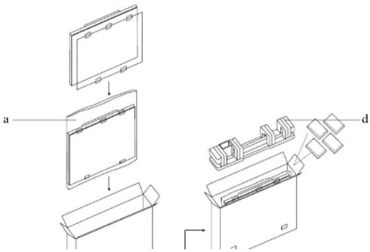
6.5 Transporting the LCD Display
To transport the LCD display for repair or shipment, place the display in its original packaging carton.
1 Place the LCD monitor inside the supplied protective bag (a).
2 Place the LCD display down in the lower box (b).
3 Place the upper box (c) on the LCD display.
4 Place the foam cushion (d) on top of the LCD display.
5 Put all the accessories in the box (if necessary).
6 Secure the upper box to the lower box with the supplied locks (e). Then close and tape the upper box.
text_image
a dCHAPTER 7: SPECIFICATIONS
7.1 Display Specifications
| PO-55F PO-55H | |||
| Panel Panel Type LED | -Backlit TFT LCD (VA Technology) LED-Backlit TFT LCD (VA Technology) | ||
| Panel Size 54.6" 54.6" | |||
| Max. Resolution FHD 1920 x 1080 FHD 1920 x 1080 | |||
| Pixel Pitch 0.630 mm 0.630 mm | |||
| Brightness 2500 cd/m | ^2 | 2500 cd/m ^2 | |
| Contrast Ratio 4000:1 4000:1 | |||
| Viewing Angle (H/V) | 178°/178° | 178°/178° | |
| Display Colour | 1.07B | 1.07B | |
| Response Time | 5 ms | 5 ms | |
| Frequency (H/V) | H Freq. | 30 kHz-80 kHz | 30 kHz-80 kHz |
| V Freq. | 56 Hz-76 Hz | 56 Hz-76 Hz | |
| Input DisplayPort | x 1 | x 1 | |
| HDMI | 1.4 x 1 | 1.4 x 1 | |
| DVI | 29-Pin DVI-I x 1 | 29-Pin DVI-I x 1 | |
| VGA 15-Pin D-Sub x 1 | 15-Pin D-Sub x 1 | ||
| External Control | RS232 in | 9-Pin D-Sub | 9-Pin D-Sub |
| Other Connectivity | USB | 2.0 x 1 (Reserved for touch design) | 2.0 x 1 (Reserved for touch design) |
| Audio | Audio In | Stereo Audio Jack (3.5 mm) x 1 | Stereo Audio Jack (3.5 mm) x 1 |
| Audio Out | Stereo Audio Jack (3.5 mm) x 1 | Stereo Audio Jack (3.5 mm) x 1 | |
| Internal Speakers | - | 10W x 2 | |
| Power | Power Supply | Internal | Internal |
| Power Requirements | 100-240Vac, 50-60 Hz | 100-240Vac, 50-60 Hz | |
| On Mode | 353W (On) | 353W (On) | |
| Stand-by Mode | < 2W | < 2W | |
| Off Mode | < 1W | < 1W | |
| Operating Conditions | Temperature | 0°C-40°C (32°F-104°F) | 0°C-40°C (32°F-104°F) |
| Humidity | 20%-80% (non-condensing) | 20%-80% (non-condensing) | |
| Storage Conditions | Temperature | -20°C-60°C (-4°F-140°F) | -20°C-60°C (-4°F-140°F) |
| Humidity | 20%-80% (non-condensing) | 20%-80% (non-condensing) | |
SPECIFICATIONS
7.2 Display Dimensions
7.2.1 PO-55F Dimensions
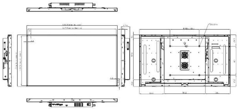
text_image
100.0mm (25mm x 20mm) 100.0mm (25mm x 20mm) 100.0mm (25mm x 20mm) 100.0mm (25mm x 20mm) 100.0mm (25mm x 20mm) 100.0mm (25mm x 20mm) 100.0mm (25mm x 20mm) 100 100 100 100 100 100 100 100 100 100 100 100 100 100 100 100 100 100 100 100 100 100 100 100 100 1007.2.2 PO-55H Dimensions
