IFP-7503 - Monitor AG Neovo - Free user manual and instructions
Find the device manual for free IFP-7503 AG Neovo in PDF.

User questions about IFP-7503 AG Neovo
0 question about this device. Answer the ones you know or ask your own.
Ask a new question about this device
Download the instructions for your Monitor in PDF format for free! Find your manual IFP-7503 - AG Neovo and take your electronic device back in hand. On this page are published all the documents necessary for the use of your device. IFP-7503 by AG Neovo.
USER MANUAL IFP-7503 AG Neovo
natural_image
Abstract geometric pattern with diagonal black and white stripes (no text or symbols)
neovo
THE DISPLAY CHOICE OF PROFESSIONALS™
TABLE OF CONTENTS
SAFETY INFORMATION .... 1
Federal Communications Commission (FCC) Notice (U.S. Only)....1
Polish Center for Testing and Certification Notice 1
Electric, Magnetic and Electromagnetic Fields ("EMF") 2
Information for U.K. only....3
North Europe (Nordic Countries) Information....4
End-of-Life Disposal....5
Waste Electrical and Electronie Equipment-WEEE 5
Turkey RoHS 6
Ukraine RoHS 6
PRECAUTIONS 7
Cautions When Setting Up....7
Cautions When Using....8
Cleaning and Maintenance....8
Notice for the Interactive Display....9
Caring for the Touch Screen....9
CHAPTER 1: PRODUCT DESCRIPTION....10
1.1 Unpacking 10
1.2 Package Contents 10
1.3 Preparing for the Installation 11
1.4 Wall Mounting Installation.... 11
1.4.1 VESA Grid 12
1.4.2 Mounting the Interactive Display on the Wall....12
1.4.3 Ventilation Requirements for Enclosure Locating 14
1.5 Mounting the Interactive Display on the Stand 15
TABLE OF CONTENTS
2.5 Connecting to a Wired Network....35
2.6 Connecting Audio Equipment 36
2.7 Connecting USB Interface Devices 37
2.8 Attaching Touch Pens....37
CHAPTER 3: USING THE INTERACTIVE DISPLAY 38
3.1 Turning on the Power 38
3.2 Selecting the Input Source Signal 38
3.3 Adjusting the Volume 39
3.4 Using Freeze Function 39
3.5 Android Functions....40
3.5.1 Accessing the Home Screen 40
3.5.2 Returning to the Previous Screen 40
3.5.3 Blanking the Screen 41
3.5.4 Activating the Writing Mode 41
3.6 Using the Touchscreen....42
3.7 Using the On-Screen Keyboard 46
CHAPTER 4: USING THE SYSTEM....47
4.1 About the Home Screen 47
4.2 Using the Assistive Menu 48
4.3 On Screen Display (OSD) Menu 50
4.3.1 OSD Menu Tree 51
4.4 Adjusting the Interactive Display .... 52
4.4.1 Audio Menu 52
4.4.2 Screen Menu 53
4.4.3 Display Menu....55
TABLE OF CONTENTS
CHAPTER 7: SPECIFICATIONS....79
7.1 Display Specifications 79
7.2 Display Dimensions....80
SAFETY INFORMATION
Federal Communications Commission (FCC) Notice (U.S. Only)

This equipment has been tested and found to comply with the limits for a Class B digital device, pursuant to part 15 of the FCC Rules. These limits are designed to provide reasonable protection against harmful interference in a residential installation. This equipment generates, uses and can radiate radio frequency energy and, if not installed and used in accordance with the instructions, may cause harmful interference to radio communications. However, there is no guarantee that interference will not occur in a particular installation. If this equipment does cause harmful interference to radio or television reception, which can be determined by turning the equipment off and on, the user is encouraged to try to correct the interference by one or more of the following measures:
• Reorient or relocate the receiving antenna.
- Increase the separation between the equipment and receiver.
- Connect the equipment into an outlet on a circuit different from that to which the receiver is connected.
- Consult the dealer or an experienced radio/TV technician for help.

Changes or modifications not expressly approved by the party responsible for compliance could void the user's authority to operate the equipment.
Use only an RF shielded cable that was supplied with the display when connecting this display to a computer device.
To prevent damage which may result in fire or shock hazard, do not expose this appliance to rain or excessive moisture.
SAFETY INFORMATION
Information for U.K. only
WARNING - THIS APPLIANCE MUST BE EARTHED.

text_image
(A) (B)Important:
This apparatus is supplied with an approved moulded 13A plug. To change a fuse in this type of plug proceed as follows:
1 Remove fuse cover and fuse.
2 Fit new fuse which should be a BS 1362 5A,A.S.T.A. or BSI approved type.
3 Refit the fuse cover.
If the fitted plug is not suitable for your socket outlets, it should be cut off and an appropriate 3-pin plug fitted in its place.

Note:
The severed plug must be
SAFETY INFORMATION

natural_image
Diagram of a plug socket with colored wires (green, blue, red) and connectors (no text or labels)How to connect a plug
The wires in the mains lead are coloured in accordance with the following code:
BLUE - "NEUTRAL" ("N")
BROWN - "LIVE" ("L")
GREEN & YELLOW - "EARTH" ("E")
- The GREEN & YELLOW wire must be connected to the terminal in the plug which is marked with the letter "E" or by the Earth symbol or coloured GREEN or GREEN & YELLOW.
- The BLUE wire must be connected to the terminal which is marked with the letter "N" or coloured BLACK.
- The BROWN wire must be connected to the terminal which marked with the letter "L" or coloured RED. Before replacing the plug cover, make certain that the cord grip is clamped over the sheath of the lead - not simply over the three wires.
SAFETY INFORMATION
End-of-Life Disposal
Your new Public Information Display contains materials that can be recycled and reused. Specialized companies can recycle your product to increase the amount of reusable materials and to minimize the amount to be disposed of.
Please find out about the local regulations on how to dispose of your old display from your local dealer.
(For customers in Canada and U.S.A.)
This product may contain lead and/or mercury. Dispose of in accordance to local-state and federal regulations. For additional information on recycling contact www.eia.org (Consumer Education Initiative).
Waste Electrical and Electronie Equipment-WEEE
Attention users in European Union private households

Disposal of Waste Equipment by Users in Private Household in the European Union. This symbol on the product or on its packaging indicates that this product must not be disposed of with your other household waste. Instead, it is your responsibility to dispose of your waste equipment by handing it over to a designated collection point for the recycling of waste electrical and electronic equipment. The separate collection and recycling of your waste equipment at the time of disposal will help to conserve natural resources and ensure that it is recycled in a manner that protects human health and the environment. For more information about where you can drop off your waste equipment for recycling, please contact your local city office, your household waste disposal service or the shop where you purchased the product.
For Private Households in the European Union. To help conserve natural resources and ensure the product is recycled in a manner that protects human health and the environment, we would like to bring your attention to the following:
SAFETY INFORMATION
Restriction on Hazardous Substances statement (India)
This product complies with the "India E-waste Rule 2011" and prohibits use of lead, mercury, hexavalent chromium, polybrominated biphenyls or polybrominated diphenyl ethers in concentrations exceeding 0.1 weight % and 0.01 weight % for cadmium, except for the exemptions set in Schedule 2 of the Rule.
E-Waste Declaration for India

This symbol on the product or on its packaging indicates that this product must not be disposed of with your other household waste. Instead it is your responsibility to dispose of your waste equipment by handing it over to a designated collection point for the recycling of waste electrical and electronic equipment. The separate collection and recycling of your waste equipment at the time of disposal will help to conserve natural resources and ensure that it is recycled in a manner that protects human health and the environment.
Batteries

For EU: The crossed-out wheeled bin implies that used batteries should not be put to the general household waste! There is a separate collection system for used batteries, to allow proper treatment and recycling in accordance with legislation.
Please contact your local authority for details on the collection and recycling schemes.
For Switzerland: The used battery is to be returned to the selling point.
For other non-EU countries: Please contact your local authority for correct method of disposal of the used battery.
According to EU directive 2006/66/EC, the battery can't be disposed improperly. The battery shall be separated to collect by local service.
PRECAUTIONS

CAUTION
RISK OF ELECTRIC SHOCK DO NOT OPEN

Symbols used in this manual
| This icon indicates the existence of a potential hazard that could result in personal injury or damage to the product. | |
| This icon indicates important operating and servicing information. |
Notice
- Read this User Manual carefully before using the interactive display and keep it for future reference.
- The product specifications and other information provided in this User Manual are for reference only. All information is subject to change without notice. Updated content can be downloaded from our web site at www.agneovo.com.
- To protect your rights as a consumer, do not remove any stickers from the interactive display. Doing so may affect the determination of the warranty period.
Cautions When Setting Up
- Do not place the interactive display near heat sources, such as a heater, exhaust vent, or in direct sunlight.
PRECAUTIONS
Cautions When Using
- Use only the power cord supplied with the interactive display.
- The power outlet should be installed near the interactive display and be easily accessible.
- If an extension cord is used with the interactive display, ensure that the total current consumption plugged into the power outlet does not exceed the ampere rating.
- Do not allow anything to rest on the power cord. Do not place the interactive display where the power cord may be stepped on.
- If the interactive display will not be used for an indefinite period of time, unplug the power cord from the power outlet.
- To disconnect the power cord, grasp and pull by the plug head. Do not tug on the cord; doing so may cause fire or electric shock.
- Do not unplug or touch the power cord with wet hands.
- When turning off the display by detaching the power cord, wait 6 seconds before re-attaching the power cord for normal operation.
- Do not knock or drop the display during operation or transportation.
Cleaning and Maintenance
- To protect your display from possible damage, do not put excessive pressure on the LCD panel. When moving your

Warning:

Unplug the power cord from the power outlet and refer to qualified service
personnel under the following conditions:
- When the power cord is damaged.
- If the interactive display has been dropped or the housing has been damaged.
◆ If the interactive display emits smoke or a distinct odor.
PRECAUTIONS
Notice for the Interactive Display
- In order to maintain the stable luminous performance, it is recommended to use low brightness setting.
- Due to the lifespan of the lamp, it is normal that the brightness quality of the interactive display may decrease with time.
- When static images are displayed for long periods of time, the image may cause an imprint on the interactive display. This is called image retention or burn-in.
◆ To prevent image retention, do any of the following:
- Set the interactive display to turn off after a few minutes of being idle.
- Use a screen saver that has moving graphics or a blank white image.
- Switch desktop backgrounds regularly.
- Adjust the interactive display to low brightness settings.
- Turn off the interactive display when the system is not in use.
◆ Things to do when the interactive display shows image retention:
- Turn off the interactive display for extended periods of time. It can be several hours or several days.
- Use a screen saver and run it for extended periods of time.
- Use a black and white image and run it for extended periods of time.
- There are millions of micro transistors inside the interactive display. It is normal for a few transistors to be damaged and to produce spots. This is acceptable and is not considered a failure.
- IMPORTANT: Always activate a moving screen saver program when you leave your display unattended. Always activate a periodic screen refresh application if the unit will display unchanging static content. Uninterrupted display of still or static images over an extended period may cause "burn in", also known
CHAPTER 1: PRODUCT DESCRIPTION
1.1 Unpacking
- This product is packed in a packaging box which contains standard accessories.
- Any other optional accessories will be packed separately.
- Considering the size and weight of the display, it is recommended that this product is carried out by two persons.
• After opening the packaging box, ensure that the included items are in good condition and complete.
1.2 Package Contents
When unpacking, check if the following items are included in the package. If any of them is missing or damaged, contact your dealer.

Interactive Display


Quick Start Guide


Remote Control


HDMI Cable

Note:
◆ Remote control is shipped with the supplied AAA batteries.
For all other regions, apply a power cord that conforms to the AC voltage of the power socket and has been approved by and complies with the safety regulations of the particular country (Type H05W-F, 2G or
PRODUCT DESCRIPTION
1.3 Preparing for the Installation
- Due to the high power consumption, always use the plug exclusively designed for this product. If an extended line is required, please consult your service agent.
- The product should be installed on a flat surface to avoid tipping. The distance between the back of the product and the wall should be maintained for proper ventilation. Avoid installing the product in the kitchen, bathroom or any other places with high humidity so as not to shorten the service life of the electronic components.
- The product can normally operate only under 3600m in altitude. In installations at altitudes above 3600m, some abnormalities may be experienced.
1.4 Wall Mounting Installation
To mount this display to a wall, you will have to obtain a standard wall-mounting kit (commercially available). We recommend using a mounting interface that complies with TUV-GS and/or UL1678 standard in North America.
To wall-mount the interactive display, screw the mounting bracket to the VESA holes at the rear of the interactive display.
IFP-6503


Warning:
Do not press too hard on the LCD panel or edge of the frame, as this may cause the device to malfunction.
Note:
- Avoid the wall-mounting kit to block the ventilation holes on the back of the display.
◆ Secure the interactive display on a solid wall strong enough to bear its weight.
♦ Lay a protective sheet on a
PRODUCT DESCRIPTION
IFP-8603

text_image
800mm 800mm1.4.1 VESA Grid
Model Name VESA Grid
| IFP-6503 600(W) x 400(H)mm | |
| IFP-7503 800(W) x 400(H)mm | |
| IFP-8603 800(W) x 600(H)mm |

Caution:
To prevent the display from falling:
For wall or ceiling installation, we recommend installing the display with metal brackets which are commercially available. For detailed installation instructions, see the guide received with
Note:
For the wall-mounting kit, use M6 mounting screws (having a length 10 mm longer than the thickness of the mounting bracket) and tighten them securely.
Unit without base weight: IFP-6503=39.4 kg /
PRODUCT DESCRIPTION
1 Mark the eight wall mount screw hole locations on the wall.

text_image
Diagram showing two hand-drawn panels with red arrows pointing to a grid, one magnified in an inset view.2 Drill eight small holes on the mounting location with the length and width 55mm x 10mm respectively.

3 Insert a plastic anchor into each hole.

PRODUCT DESCRIPTION
5 Align and hook the dual wall mount on the interactive display to the wall mount.

text_image
Dual Wall Mount x 26 Secure the dual wall mount and the wall mount with the two screws.

text_image
Technical diagram showing a mechanical assembly with a magnified inset labeled 'x2' and an arrow indicating direction.1.4.3 Ventilation Requirements for Enclosure Locating
Note:
- Keep clearances around the interactive display according to the minimum dimensions as illustrated.
- Never cover the ventilation holes or insert anything into the housing.
Do not place the interactive display in a confined space, such as a cabinet or imbedded closet. Place the display on a sturdy, level surface and make sure an appropriate ventilation is provided.

Warning:
Make sure the power cord of the
PRODUCT DESCRIPTION
1.5 Mounting the Interactive Display on the Stand
To mount the interactive display on the stand, you need the following items:

natural_image
Three technical line drawings of structural beams or supports, no text or symbols presentLeft Leg x 1 Right Leg x 1 Wall Bracket x 1

natural_image
Three technical line drawings of mechanical components: a vertical bar, a cylindrical component with a handle, and a elongated rod (no text or symbols)Tray x 1 Wheel x 4 Wall Hanging Strip x 2

Bolts x 14 M12 Spring Screws x 2 Phillips Adjustable (M8×25) Pad x 4 (M6×130) Screwdriver Wrench x1
(self-provided)
1 Attach the spring pad to the wheel. Then adjust the wheel to the brake state and rotate it into the leg. Repeat the step for the remaining wheels.

PRODUCT DESCRIPTION
2 Install and secure the wall bracket to the leg with the provided bolts. Make sure the wall bracket and the leg are properly aligned as indicated with black arrows in the below image.

text_image
Bracket holes 1 2 3 4 5 63 Install and secure the other leg to the wall bracket with the provided bolts.

natural_image
Simple line drawing of a metal frame with a hammer and arrow indicating direction (no text or symbols)Note:
• Wall bracket hole position suggestions:
| Monitor Size Matching hole position | |
| 55" 3 | ^m and 6 ^h holes |
| 65"- 70" 2 | ^m , 5 ^h hole |
| 75"- 86" 1 | ^a and 4 ^h hole |
PRODUCT DESCRIPTION
4 Assemble the tray between the two columns as follows:
a) Insert the tray into the positioning bolt on the column.
b) Snap the tray into the positioning bolt.
c) Tighten all bolts.

text_image
Technical diagram showing a mechanical setup with labeled components and a magnified detail view of the assembly.5 Align and secure the wall hanging strip on both sides of the interactive display. Secure the wall hanging strips to the display with the provided bolts.

PRODUCT DESCRIPTION
6 Hang the interactive display assembly to the wall bracket.
Then secure the safety bolts of the wall hanging strips to lock the interactive display to the stand.

natural_image
Technical line drawing of a mechanical assembly with a magnified inset showing a component detail (no text or symbols)Mounting the interactive display on the stand is complete.

Warning:
Make sure the wheel brakes are locked. This step requires at least 2 professionals to complete.
PRODUCT DESCRIPTION
If the interactive display's wall mounting bracket does not match with the wall mounting bracket of the stand, then do the following:
1 Secure the wall hanging board to the wall bracket. Make sure that the side of the wall hanging board with the locking hole is facing the front as indicated with black arrows in the below image.

text_image
Technical diagram showing a mechanical assembly with labeled components and directional arrows indicating assembly or movement.2 Hang the interactive display assembly to the wall bracket. Then secure the safety bolts of the wall hanging strips to lock the interactive display to the stand.

PRODUCT DESCRIPTION
1.6 Installing the Wi-Fi Module
To use wireless connectivity, you need to install the Wi-Fi module to the interactive display.
1 Remove the two screws from the Wi-Fi module slot cover.

natural_image
Illustration of a hand holding a cylindrical object with a ring, next to a flat electronic device (no text or symbols visible)2 Remove the Wi-Fi module slot cover.

text_image
G G G3 Insert the Wi-Fi module into its slot in the interactive display.

PRODUCT DESCRIPTION
1.7 Interactive Display Overview
1.7.1 Control Panel

text_image
Diagram showing a monitor setup with labeled components and an icon of a pen inside a device.1 [+] POWER button with LED indicator
- Short press (<3 seconds) to turn the display on or off without shutting down the system.
- Long press (>3 seconds) to shut down the system.
LED indicator:
PRODUCT DESCRIPTION
1.7.2 Input/Output Terminals

PRODUCT DESCRIPTION
1 3.0
Connects to a USB interface device.
2 AUDIO OUT
Connects audio signals output (3.5 mm Stereo Audio Jack).
3 RS232
Connects RS232 input from external equipment.
4 LAN
For internet connection with an Ethernet cable.
5 AUDIO IN
Connects audio signals input (3.5 mm Stereo Audio Jack).
6 VGA
Connects VGA signals input.
7 2.0
Connects to a USB interface device.
8 SPDIF
Connects digital audio signals output.
9 \~
AC power input.
10 Main Power
Switches the main power on/off.
11 HDMI OUT
Connects HDMI signals output.
12 TOUCH 1 (USB Type-B)
Connects USB for touch screen control.
Connects USB for touch screen control.
14 HDMI 1
Connects HDMI signals input.
15 HDMI 2
Connects HDMI signals input.
16 HDMI 3
Connects HDMI signals input.
17 3.1#(USB Type-C)
Connects to a USB interface device.
PRODUCT DESCRIPTION
1.8 Remote Control
1.8.1 General Functions

text_image
1 2 3 4 5 6 7 8 9 10 Input User Frames 11 12 13 14 15 16 17 18 19 20 21 22 23 24 25 26 27 F1 F3F2 F4 F5F5 Control Panel Interface Control Panel Interface Control Panel Interface1 [●]Power button: Turns the system on or shuts down.
2 [OK] MUTE button: Turns the mute function on or off.
3 [START] Start button: Opens the Start menu (Windows OS).
4 [SPACE] Space button: Functions as "Space" keyboard key.
5 [Alt + F4] "Alt" + "F4" button: Functions as "Alt" + "F4" keyboard keys (Window OS).
6 [Alt + Tab] "Alt"+"Tab" button: Functions as "Alt"+"Tab" keyboard keys (Window OS).
7 [Number] Number buttons: Enters numbers.
8 [Display] Display button: Displays channel information.
9 [Φ Re-sync button: Not supported.
10 [Input] Source button: Opens TouchMenu > General settings.
11 [Home] Home button: Returns to the Home screen (Android OS).
12 [Menu] Menu button: Opens TouchMenu > OSD Menu.
13 [●] Red button:
PRODUCT DESCRIPTION
21 [Enter] Enter button:
Confirms your selection or saves the modifications.
22 [Back] Back button:
Returns to the previous screen (Android OS) or exits the OSD menu.
23 [PgUp] Page Up button:
Functions as "PageUp" keyboard key.
24 [CH.+] [CH.-] Channel button:
No function.
25 [VOL+] [VOL-] Volume button:
Adjusts volume on internal or external audio sources.
26 [PgDn] Page Down button:
Functions as "PageDown" keyboard key.
27 [F1-F12] F1-F12 buttons:
Function as "F1" to "F12" keyboard keys.
Note:
- While the interactive display is powered on and you press the keyboard button, the POWER button LED indicator blinks red once and then turns back white.
You need to press the Red button and the Yellow button at the same time to completely unlock the screen.
PRODUCT DESCRIPTION
1.8.2 Inserting the Batteries in the Remote Control
The remote control is powered by two 1.5V AAA batteries.
To install or replace batteries:
1 Unlatch and then remove the battery compartment cover.
2 Align the batteries according to the (+) and (-) indications inside the battery compartment.
3 Replace the battery compartment cover.

natural_image
Three technical line drawings of a vehicle interior with arrows indicating movement or change, no text or symbols present.1.8.3 Handling the Remote Control
- Do not subject to strong shock.
- Do not allow water or other liquid to splash the remote control. If the remote control gets wet, wipe it dry immediately.
- Avoid exposure to heat and steam.
- Other than to install the batteries, do not open the remote control.

Caution:
The incorrect use of batteries can result in leaks or bursting. Be sure to follow these instructions:
Place "AAA" batteries matching the (+) and (−) signs on each battery to the (+) and (−) signs of the battery compartment.
Do not mix battery types.
Do not combine new batteries with used ones. It causes shorter life or leakage of batteries.
Remove the dead batteries immediately to prevent them from liquid leaking in the battery compartment. Don't touch exposed battery acid, as it can damage your skin.
Note:
◆ If you do not intend to use
PRODUCT DESCRIPTION
1.8.4 Operating Range of the Remote Control
Point the top of the remote control toward the display's remote control sensor (on the left or right side) when pressing a button.
When using the remote control, the distance from the remote control to the sensor on the display should be less than 8m/26ft, and the horizontal and vertical angles should be less than 30°.

text_image
30°30°CHAPTER 2: MAKING CONNECTIONS
2.1 Connecting the Power
Note:
To operate the interactive display, ensure to use the correct power cord that matches the power outlet in your region.
1 Connect one end of the power cord to the AC IN connector on the interactive display.
2 Connect the other end of the power cord to a power outlet or a power supply.
3 Set the Main Power switch to ON.

text_image
Architectural floor plan diagram with labeled equipment and a zoomed-in electrical outlet detailMAKING CONNECTIONS
2.2 Connecting a Computer or Portable Device
2.2.1 Using VGA (D-Sub) Input
Connect one end of a VGA cable to the VGA connector of the interactive display and the other end of a VGA cable to the VGA OUT connector of the computer.
For audio input, connect one end of an audio cable to the AUDIO IN connector of the interactive display and the other end of an audio cable to the AUDIO OUT connector of the computer.

text_image
VGA AUDIO IN AudiO IN VGA ComputerMAKING CONNECTIONS
2.2.2 Using RS232 Input
Connect one end of a RS232 serial cable to the RS232 connector of the interactive display and the other end of an RS232 serial cable to the RS232 connector of the computer.

text_image
RS232 RS232 RS232 Computer2.2.3 Using HDMI Input
MAKING CONNECTIONS
2.2.4 Using the Touch Module
Interactive display has touch screen functionality which allows you to connect a computer to the display and control the computer's interface via touch gestures on the display. To use this touch screen function, connect the USB cable to the TOUCH 1 or TOUCH 2 port of the display and a computer or USB cable to the 3.1# port of the display and a computer.
In addition, perform the following connection:
- For TOUCH 1, connect one end of the HDMI cable to the HDMI 1 or HDMI 2 port of the display and the other end of the HDMI cable to the HDMI OUT port of the computer.
- For TOUCH 2, connect one end of the HDMI cable or VGA cable to the HDMI 3 port or VGA port of the display and the other end of the HDMI cable or the VGA cable to the HDMI OUT port or VGA OUT port of the computer respectively.
- For USB type-C, connect one end of the USB cable to the 3.1 port of the display and the other end of the USB cable to the USB type-C port of the computer.
For compatibility options, refer to the following table:
| HDMI 1 HD | MI 2 HDMI 3 V | GA | ||
| TOUCH 1 O O | XX | |||
| TOUCH 2 XX | O O |
TOUCH 1

MAKING CONNECTIONS
TOUCH 2

text_image
HDMI 3 TOUCH 2 IIDMI 3 TOUCH 2 VGA VGA VGA OUT USB IIDMI OUT ComputerUSB Type-C

MAKING CONNECTIONS
Note:
◆ The touch driver will be installed automatically for the following operating systems:
- One-touch point for Windows 2000/XP/Vista/CE 6.0 and macOS.
- Multi-touch point Windows 7/8/10/11, Android/Linux (kernel version 3.5+) and Chrome OS (39 or above).
Certain touch gestures, such as zoom-in, zoom-out and rotate, may not work depending on the application or software your computer supports.
This Touch USB port works only for the touch screen functionality and does not support the external USB devices, such as MP3, printer, and hard drive, or other devices.
2.3 Connecting External Equipment (Video Player)
Connect one end of an HDMI cable to the HDMI 1, HDMI 2, or HDMI 3 connector of the interactive display and the other end of an HDMI cable to the HDMI OUT connector of the video player.

text_image
HDMI 1 HDMI 1 HDMI 2MAKING CONNECTIONS
2.4 Connecting a Display Device
Connect one end of an HDMI cable to the HDMI OUT connector of the interactive display and the other end of an HDMI cable to the HDMI IN connector of the display device.

text_image
HDMI OUT HDMI IN Display DeviceMAKING CONNECTIONS
2.5 Connecting to a Wired Network
Connect one end of a network cable (RJ45) to the LAN connector of the interactive display and the other end of a network cable to a network hub, switch, or router.

natural_image
Architectural floor plan showing room layouts and structural elements (no text or labels)
Network Hub / Switch / Router
MAKING CONNECTIONS
2.6 Connecting Audio Equipment
Connect one end of an audio cable to the AUDIO OUT connector of the interactive display and the other end of an audio cable to the AUDIO IN connector of the audio device.
For digital audio output, connect one end of an audio cable to the SPDIF connector of the interactive display and the other end of an audio cable to the SPDIF IN connector of the audio device.

text_image
SPDIF AUDIO OUT AUDIO OUT SPDIF Audio Device SPDIF IN AUDIO INMAKING CONNECTIONS
2.7 Connecting USB Interface Devices
Connect a USB interface device to 2.0 or 3.0 ports of the interactive display.

text_image
3.0 x2 3.0x2 3.0x2 3.0x2 2.0 2.0USB Interface Device (Keyboard/ Mouse/ USB Storage, and more)
2.8 Attaching Touch Pens
Attach the touch pen to the magnetic areas on the interactive display's front panel.
CHAPTER 3: USING THE INTERACTIVE DISPLAY
3.1 Turning on the Power

text_image
POWER button 1 Plug the power cord to a power outlet or power supply. 2 Set the Main Power switch to ON. 3 Press the button to turn the interactive display on. When the interactive display is turned on, press the button to turn off the interactive display.3.2 Selecting the Input Source Signal

text_image
7 8 9 Input 0 Input Button Input Button 1 Press the Input button.Note:
The interactive display still consumes power as long as the power cord is connected to the power outlet. Disconnect the power cord to completely cut off power.
Note:
◆ If the selected input source signal is not connected to the interactive display or is turned
USING THE INTERACTIVE DISPLAY
3.3 Adjusting the Volume

text_image
VOL+/VOL- buttonsPress the VOL- or VOL+ button to adjust the volume level.
3.4 Using Freeze Function

text_image
1 2 3 4 5 6 7 8 9 Caser 0 Input/Resistone Blue buttonNote:
After pressing the VOL- or VOL+ button, the volume menu is displayed on the screen automatically.

Press the 🎧 button to mute the audio. When muted, the 🎧 icon appears on the screen.
USING THE INTERACTIVE DISPLAY
3.5 Android Functions
3.5.1 Accessing the Home Screen

text_image
4 5 6 7 8 9 Entry 0 Input Mode Home Home buttonPress the Home button to access the Home screen of the system.
3.5.2 Returning to the Previous Screen

USING THE INTERACTIVE DISPLAY
3.5.3 Blanking the Screen

text_image
Display 0 Input New Button Screen backlight button Ctrl+1 Play VOL+1 Up DownPress the ☐ button to blank the screen. The screen turns black. Press the ☐ button again to turn on the screen backlight.
3.5.4 Activating the Writing Mode

USING THE INTERACTIVE DISPLAY
3.6 Using the Touchscreen
In addition to the remote control, you can also operate your interactive display using the touch gestures as described in the tables below.
For Android
| Action Touch Gesture Function | ||
| Touch |  | Touch to open clickable items on the screen, such as apps, Assistive menu options, and more.Note:◆ Always touch the screen with your finger or with the supplied touch pen.◆ Do not touch the screen with sharp, metallic objects that could scratch the screen's coating. |
| Touch and hold |  | • Review and control the appa) On the Apps screen, touch and hold the app icon that you want to review.b) Drag the app onto the App info at the top of the screen and then release.The app's information screen opens. |
| Drag or swipe |  |  |
USING THE INTERACTIVE DISPLAY
| Action Touch Gesture Function | ||
| Touch and hold (continued) |  | • Touch and hold on the Home screen to add a widget or change the Home screen wallpaper. |
| Drag or swipe (continued) |  | |
| Zoom Zoom in | 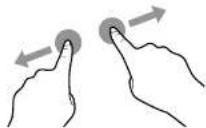 Zoom out Zoom out | • Zoom in and zoom out on the image.For example:Zoom in Zoom out Zoom out |
USING THE INTERACTIVE DISPLAY
| Function Touch Gesture Action | |||
| Tap |  | Touch the screen once. | |
| Double-tap |  | Touch the screen twice. | |
| Right-tap |  | Touch and hold on the target until a blue ring appears. Then release your finger. | |
| Drag |  | Touch the screen and drag with one finger to the left or to the right. | |
| Note:♦ For Windows Vista, Windows 7, Windows 8, Windows 10, and Windows 11. | |||
| Selection | Touch the screen and drag with one | ||
USING THE INTERACTIVE DISPLAY
| Function Touch Gesture Action | ||
| Primary action |  | Touch the target to invoke its primary action. For example, launch an app or execute a command. |
| Pan |  | Touch the screen and slide for panning interactions, moving items, drawing, or for writing. Slide can also be used to target small, densely packed elements by scrubbing (sliding the finger over related objects, such as radio buttons). |
| Select, command, and move |  | Touch the screen and swipe to select, command, and move. Sliding your finger a short distance, perpendicular to the panning direction, selects objects in a list or grid and displays the app bar with related commands when objects are selected. |
| Zoom Touch | the screen and pinch or stretch to  | zoom out or zoom in respectively.The pinch and stretch gestures are more commonly used for resizing but also enable to move to the beginning, end, or anywhere within content with semantic |
USING THE INTERACTIVE DISPLAY
| Function Touch Gesture Action | ||
| Scrolling |  | Touch and drag the screen with one or two fingers up or down. |
| Zoom | Zoom in 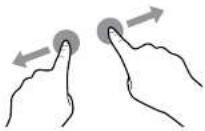 Zoom out Zoom out  | Touch the target and move your two fingers apart or toward each other to zoom in or zoom out respectively. |
3.7 Using the On-Screen Keyboard
CHAPTER 4: USING THE SYSTEM
4.1 About the Home Screen
After you power on the system, you will see the Home screen. On the Home screen, you can view the current date and time, access the Assistive menu and various apps, check system status, and remote code.

text_image
04:15 Time: 9:37 1 2 3 4 1 5Item Description
| 1 Assistive menu Quick access for moving backwards, accessing the Home screen, managing recently used apps, opening various apps, enabling annotation function, and rearranging tools icons in the Assistive menu. Refer to pages 48-49. | |
| Note:◆ The Assistive menu icons / are visible on both sides of the interactive display. | |
| 2 | Remote Code Wireless display verification passcode from Bytello Share. |
| 3 | Date and Time Displays the current date and time. Adjust the settings in Settings menu. Refer to page 58. |
USING THE SYSTEM
4.2 Using the Assistive Menu
The Assistive menu can be accessed on either sides of the interactive display by touching /. For more convenient access, you can touch and hold on the Assistive menu icon to slide it up or down. Assistive menu icons are always visible on the screen regardless of your location in the user interface.
To use the Assistive menu, do the following:
1 Touch the / icon on either sides of the interactive display.
The Assistive menu opens.
2 Touch any of the following Assistive menu items:
- Back 📄: Returns to the previous screen.
Note:
◆ Back function is available only if the source is Android.
- Home 🔒: Accesses the Home screen.
- Recently Used Apps ●Manages recently used apps. Do any of the following:
- To reopen: Touch the app.
- To close: Swipe the app to the left or to the right or touch
- To close all apps: TouchClean All.
Note:
- Recently used apps function is available only if the source is Android.


USING THE SYSTEM
- App Shortcuts: Quick access for common apps. Touch any of the following icons: opens Meetboard, opens Finder, opens web browser, and opens cloud storage (requires user authentication at first log in). To access more apps, touch
- Tools: The interactive display features several tools, such as screen capture, screen recording, and more. Touch any of the following icons: Annotations to enter writing mode, Prop to open screen capture tool, Record to open screen recording tool, Menu to open General settings menu. To access more tools, touch Then touch any of the following icons: Stopwatch, AirClass to start online class, Spotlight to emphasize an area on the screen, Freeze to freeze the screen, Spotlight to count down time for events, or ScreenLock to prevent access to the interactive display.
- Annotation App ☐: Opens the Annotation app and enters writing mode.
Note:
The Annotation app cannot be accessed while using the Meetboard app.
To rearrange tool icons in the Assistive menu, touch > Edit. Touch next to the icon you want to remove and then touch next to the icon you want to add. You can add up to 4 tool shortcuts to the Assistive menu.

text_image
Top 100% Desktop Format > 100% Desktop Desktops, AirPass, Sprinting, Finance, Email SOMES.COMTo close the Assistive menu, touch anywhere on the screen outside the Assistive menu.
USING THE SYSTEM
4.3 On Screen Display (OSD) Menu
| # | Menu Navigation | Operation | |
| Remote Control Touch | Gesture | ||
| 1 | Displays the Audio menu. Press the Menu button. Swipe the screen from  | the bottom to up and then touch -... | |
| 2 | Enters the submenu.  | 1 Press the ◀ or ▶ button to select the main menu item. 2 Press the ▼button to enter the submenu. 3 Press the ◀, ▶, ▶▼button to select the submenu item. 4 Press the Enter button to enter the adjustment mode. | 1 Touch the main menu item. 2 Touch the submenu item to select it. |
USING THE SYSTEM
When settings are modified, all changes are saved when the user does the following:
• Proceeds to the another menu.
- Exits the OSD menu.
- Waits for the OSD menu to disappear.
Note:
Availability of some menu items depend on the input source signal or selected setting. If the menu is not available, it is disabled and grayed out.
4.3.1 OSD Menu Tree

text_image
Audio Screen Display Adjust 54 Volume 4 0 Balance -38USING THE SYSTEM
| Main Menu Submenu Remarks | ||
| 2. Screen • 4:3 | See page 53. | |
| • 16:9FullAnti-Burn-inTMEye CareAuto LightPower SavingDCR | ||
| 3. Display • Brightness | See page 55. | |
| • ContrastHueSharpness | ||
| 4. AdjustNote: This menu is only supported if the input source is VGA. | • H PositionV PositionClockPhaseAUTO | See page 56. |
4.4 Adjusting the Interactive Display
4.4.1 Audio Menu

Press the Menu button.
The Audio menu opens automatically
USING THE SYSTEM
| Item Function Operation Range | |||
| Volume | Adjusts the volume. | 1 Press the Enter button to select the setting.2 Press the ◀ or ►button to adjust the value. | 0 to 100 |
| Bass Adjusts to increase or decrease lower-pitched sounds.Note: This item can be adjusted only if the Predefined Audio Mode is set to Custom. | -5 to 5 | ||
| Treble Adjusts to increase or decrease higher-pitched sounds.Note: This item can be adjusted only if the Predefined Audio Mode is set to Custom. | -5 to 5 | ||
| Balance Adjusts to emphasise the left (L) or right (R) audio output balance. | -50 to 50 | ||
| Mute Mutes the volume.Note: If the sound is muted then all the Audio menu items become unavailable except for the Volume. | Press the Enter button. On | Off | |
4.4.2 Screen Menu
< Audio Screen Display Adjust
1 Press the Menu button.
USING THE SYSTEM
| Item Function Operation Range | |||
| Anti-Burn-inTM Prevents image retention. Press the Enter button. On | Off | ||
| Eye Care Enable or disables the blue light filter function. When enabled, it decreases the amount of blue light displayed on the screen, ensuring users a comfortable viewing experience by reducing eyestrain after long periods of use. | On Off | ||
| Auto Light Adjusts the backlight of the interactive display automatically depending on the amount of ambient light. | On Off | ||
| Power Saving Enable or disables power saving mode. When the interactive display turns into power saving mode, the screen turns black and the Power button LED indicator starts to flash red and white alternatively. Note: The Power Saving function depends on standby settings configured in System Settings > Power Settings menu. | On Off | ||
| DCR (Dynamic) | Activates DCR. This feature provides automatic adjustment of | Press the Enter button. On | Off |
USING THE SYSTEM
4.4.3 Display Menu

text_image
Audio Screen Display Adjust 88 Brightness 93 Contrast 50 Hue 50 Sharpness Standard Right Soft Custom Standard Cast Plan1 Press the Menu button.
The Audio menu opens automatically.
2 Press the ◀ or ▶ button to select Display menu.
3 Press the button to enter submenu.
4 Press the ◀, ▶, ▲, or ▼ button to select the submenu item.
| Item Function Operation Range | |||
| Predefined Display Modes | Selects the predefined display mode. | Press the Enter button. Standard | BrightSoftCustom |
| Predefined Colour Temperature Modes | Selects the predefined colour temperature mode. | StandardColdWarm | |
| Brightness Adjust | is the luminance of the screen image.Note: This item can be adjusted only | 1 Press the Enter button to select the setting.2 Press the ◀ or ► button to | 0 to 100 |
USING THE SYSTEM
4.4.4 Adjust Menu
Note:
♦ Adjust menu items are only available if the input source is VGA.

other
| Category | Value | |---|---| | H Position | 55 | | V Position | 7 | | Clock | 50 | | Phase | 8 | AUTO1 Press the Menu button.
The Audio menu opens automatically.
2 Press the ◀ or ▶ button to select Adjust menu.
3 Press the ▼ button to enter submenu.
4 Press the ▲ or ▼ button to select the submenu item.
| Item Function Operation Range | |||
| H Position Moves | the image to the right or to the left. | 1 Press the Enter button to enter the adjustment mode. | 0 to 100 |
| V Position Moves | the image up or down. 0 to 100 | ||
| Clock Adjusts the | width of the image. 0 to 100 | 2 Press the ◀ or ▶ button to adjust the value. | |
| Phase Adjusts to | improve the focus, clarity, and stability of the image. | 0 to 100 | |
| AUTO Adjusts the | screen image automatically. | Press the Enter button. | N/A |
USING THE SYSTEM
4.5 Configuring System Settings
In Settings menu, you can configure various system settings.
To access the Settings menu, do the following:
1 On the Home screen, touch □ > ◯
The Settings menu opens.

text_image
Wireless & Network WiFi: 98000000000 Personal Input & Output Application System About Wireless & Network WiFi Ethernet Hotspot Bluetooth VIPS On > On > On > No VIPS unstandard >2 Configure any of the following settings:
Wireless & Network:
- Wi-Fi: Connects to an available wireless access point. Enter the access password if prompted
- Ethernet: Connects to LAN through a wired connection. Configures IP settings manually (Obtain IP Address Automatically is disabled) or automatically (Obtain IP Address Automatically is enabled).
- Hotspot: Shares interactive display's Internet connection to other devices through hotspot and configures hotspot DHCP settings (if necessary).
- Bluetooth: Connects to other Bluetooth devices.
- VPN: Sets up and manages virtual private networks for safe and secure online communication.
USING THE SYSTEM
Application:
- Manages apps that are installed to the interactive display. You can enable or disable the app, force stop it, enable or disable notifications from the app, mange storage, open the app by default, monitor memory usage, and modify advanced settings.
System:
- Date & Time: Configures date and time settings.
- Language & Keyboard: Sets system language and configures keyboard settings.
- Password: Sets lock screen password and advanced settings password.
- Power Settings: Configures power settings. Refer to 59.
- Anti-Burn-in™: Prevents the display from "burn-in" or "afterimage" symptoms when the display is not being in use for a period of time. Select the time interval for executing the Anti-Burn-in™ function.
- Email: Configures email settings. For example for sending drawings from Meetboard to your email.
- Storage: Manages the internal storage.
- System Update: Updates the system when a new version is available.
- Security: Configures credential storage settings.
- Advanced Settings: Configures advanced settings. To access the Advanced Settings, you need to set the Advanced Lock Password in the Security menu. Then enable or disable installing apps from third-party app stores, enable or disable accessing the USB drive, SAMBA service, and reset the settings to the factory defaults.
About:
USING THE SYSTEM
4.6 Power Settings
In the Power Setting menu, you can configure booting options, system power options, and schedule boot-time.

text_image
Windows & Network Personal Input & Output Application Options About Power Settings Startup Channel Startup Channel Sendry After (Startup/Back Screen) Sendry After 15 minutes Without Operation Power (Off After 15 minutes Without Operation) Switching Power (Off Extension) Add Road Task Add Off Task4.6.1 Booting Options
In the Startup Channel menu, set the default source at boot up and configure system standby setting.
4.6.1.1 Startup channel
Select the default startup channel among:
- Last shutdown channel: Input source is the same as at last boot.
- Meetboard/HDMI1/HDMI2/HDMI3/Type-C/VGA: Startup channel is Meetboard, HDMI1, HDMI2, HDMI3, Type-C, or VGA respectively.

USING THE SYSTEM
Note:
In standby mode, the POWER button is flashing red and white alternatively.
4.6.2 Scheduling
In the Scheduling menu, enable or disable displaying power off reminder before shutting down the system and schedule boot and off tasks.
- Add Boot Task: Adds a boot schedule. Select the time and day.

text_image
Add Boot Task 12 56 1 : 57 AM 2 58 PM Sun Moit Tue Wed Thu Fri Sat Cancel- Add Off Task: Adds a power off schedule. Select the time and day.

CHAPTER 5: USING THE APPS
5.1 Accessing Apps
Some apps, such as Meetboard, Finder, and Bytello Share are accessible directly from the Home screen. Other apps that are installed to the system can be accessed through the Apps screen.
To access the Apps screen, do the following:
1 On the Home screen, touch ☐.
The Apps screen opens.

text_image
Screenshot of a macOS desktop with app icons and status bar showing 'OK', 'Cancel', and 'Help'2 On the Apps screen, touch any of the following apps:
- Browser: Opens the web browser for surfing the Internet.
Note:
◆ Make sure your interactive display is connected to the Internet.
- Bytello Share: Mirrors the screen of your portable device to the interactive display and more. Refer to 68.
- Cloud Drive: Configures cloud storage access settings. These settings may be prompted also in
USING THE APPS
- WPS Office: Views PDF files, opens and edits different files including Microsoft Word, PowerPoint, Excel, and text files. You can also create new spreadsheets, presentations, memos, and documents.

text_image
File Explorer Share Name File File List Share Share List Share List Share List Share List Share List Share List Share List Share List Share List Share List Share List Share List Share List Share List Share List Share List Share List Share List Share List Share List Share List Share List Share List Share List Share List Share List Share List Share List Share List Share List Share List Share List Share List Share List5.2 Meetboard Apps
Meetboard is an interactive app that enables you to make drawings for demonstrating ideas on the display. The drawings can be saved to the device memory, connected portable disk, or cloud storage, or easily shared via QR code or email.
To use the Meetboard app, do the following:
1 Touch the ● icon on the Home screen or the ● icon on the Apps screen. The Meetboard app opens.

USING THE APPS
Note:
If the pen type is then the Meetboard tries to recognise your image automatically while you are drawing it on the writing board and provides image hints. If your image matches with the preset image, touch it to replace your image with the preset image. For example:

natural_image
Simple line drawing of a horse head with nine abstract icons arranged in a grid (no text or symbols)- Touch More: Adds an interactive ruler, 2D or 3D shape, customisable table, mind map, or preset grid to the writing board.
- Touch 📊 Sticky-Notes: Adds a note to the writing board.
- Touch ⚫ Menu > ☑ Theme: Adds a preset template, background colour/image to your drawing. To set a preset template or background colour, touch Template tab or Background tab respectively. Select the template or your preferred background colour and touch OK. To select an image, tap Background > Images > + and select your preferred image. To cancel editing the theme, touch Cancel.
Template selection Colour/image selection


USING THE APPS
3 To control the drawing on the board, use the following actions:
- Select: Selects objects on the writing board. After selecting the object or part of it, you can change its colour, detect a character (SmartWrite), search similar objects online, flip it, rearrange on the screen, clone, or delete it.

natural_image
Simple line drawing of a smiling sun with rays (no text or symbols)- Erase: Touch ◆ Eraser and select the eraser size. Then put your fist or palm on the board and move to the area that needs to be erased. To clear the entire writing board, touch ☒ Clean All.
- Preview: Provides a preview of the writing board.
- Undo: Reverses the most recent action on the writing board.
- Redo: Restores the most recent action on the writing board.
- Add: Adds a new page.
- < Previous: Moves to the previous page if there are multiple pages in the file.
-> Next: Moves to the next page if there are multiple pages in the file.
Note:
◆ Touch on the page count ( ) to thumbnail all pages and remove unnecessary pages.
USING THE APPS
- Menu > ✗ Send Email: Emails the drawing. If you are sending the drawing by email for the first time, you are prompted to configure your email settings. Follow the on-screen instructions to complete the configuration.

After all settings are configured, return to the Meetboard app and send the drawing by email. The drawing is added as an attachment.
Note:
To send an email, make sure the interactive display is connected to the Internet.
Share: Displays a QR code on the screen that directs to the online location where the drawing can be downloaded to any portable device that is connected to the same Wi-Fi with the interactive display.

USING THE APPS
5.3 Annotation Tool
Annotation is an app that provides a more fluid discussion of visual images by annotating anywhere on the display.
Note:
The Annotation app cannot be accessed while using the Meetboard app.
To use the Annotation app, do the following:
1 In Assistive menu, touch
The system enters to the writing mode and displays the Annotation control bar on the screen.

2 Draw directly on the screen with the default pen thickness and colour. To change the thickness and colour, touch and hold the Pen or Brush icon and do the modifications.
3 After the drawing is finalised, touch any of the following:
- Clean: Erases the drawing. To erase part of the drawing, use your fist or palm.
- Save: Saves the drawing by default to the Storage > Meetboard > Annotations folder. You can access it using Finder. If you want to insert the drawing to the Meetboard, share by QR code, or save to the cloud storage, save the drawing first and then touch More > Insert/ Share/ Cloud respectively.
- Select: Select the location where to save the image in the More menu.
4 To exit the Annotation app, touch ✗ Close.
• • • •
USING THE APPS
To start using the Finder app, do the following:
1 On the Home screen, touch 📄 or on the Apps screen, touch
The Finder Home screen opens.
2 Touch any of the following:
- Storage that you want to manage.
- Grid/List: Displays the content as grid or as list.
- Sort: Sorts the content by name (ascending or descending), time, size, or type.
- Select: Selects items for copy (Copy), paste (Paste), cut (Cut), deletion (Delete), rename (Rename) (only available for individual item), or creating a shortcut/sending to another storage device Send. While in selection mode or paste mode, touch Close to close the selection or paste mode.
- Create: Adds a folder.
5.5 Cloud Drive
To access your cloud storage from various apps installed on the interactive display, you are prompted to enter user credentials at first log in.
To access your cloud storage from the interactive display, do the following:
1 On the Home screen, touch 📄 > or Assistive menu >
4 Enter your login credentials and follow the on-screen instructions to complete the authentication process.
Google Drive Login OneDrive Login


text_image
Create Account Microsoft Sign in Create options or Options Be accepted? I have been Get options your account? Save Save Sign-in options.5.6 Bytello Share App
With the Bytello Share app, you can mirror the display's screen on your portable device for hands-on annotation, mirror the screen of your device on the display, or use your device as a remote control for the display.
Bytello Share is accessible either by downloading the sender app to your portable device or by sharing the screen via Airplay, Chromecast, or Miracast.
Note:
To share the screen via Airplay, Chromecast, or Miracast, please refer to the "How to share screen without client?" section in the Bytello Share User Guide. The User Guide can be accessed from the launcher screen.

USING THE APPS
5 Open the Bytello Share app on your portable device and enter the remote code that is visible on the Home screen and launcher screen.
Launcher Screen Portable Device

text_image
扫码支付 316 978
After the connection is established, the following screen opens on your portable device:

6 Touch any of the following:
- Screen share > Start: Shares your portable device's screen to the interactive display. For example, in iOS touch Start Broadcast to start sharing the screen.

USING THE APPS
Note:
To configure Bytello Share settings, such as access permissions, screen sharing without client, general settings including device name, starting the app on boot, code refresh rate, and more, touch
Menu > Settings on the launcher screen.
To mange the connected devices, touch Devices (#) 📄 on the launcher screen. Then touch any of the following icons:
- Initiates the device to start screen casting.
- 📋: Sends files from the interactive display to the device.
- 8: Authorizes the device to manage other senders and approve requests from them.
- ☑ Disconnects the device.
CHAPTER 6: APPENDIX
6.1 Warning Messages
| Warning Messages Cause Solution | ||
 | The resolution or the refresh rate of the graphics card of the computer is set too high. | · Change the resolution or the refresh rate of the graphics card. |
 | The interactive display cannot detect the input source signal. | · Check if the input source is turned ON.· Check if the signal cable is properly connected.· Check if any pin inside the cable connector is twisted or broken. |
6.2 Supported Media Formats
Video Format
| File Extensions | Codec | ||
| Video Audio | Maximum Transmit Ratio | ||
| .3gp/3GP2 mpeg1/2 M | peg1/2 Layer1/2/3, A | ACLC, vorbis,LPCM, AMR-NB | Spec: Max Solution: 1920 x 108060 Fps, 80 Mbps |
| Mpeg-4 | |||
| H.263 | |||
| H.264 Spec: Max Solution: 8192 x 4320 | 60 Fps, 200 Mbps | ||
APPENDIX
| File Extensions | Codec | ||
| Video Audio | Maximum Transmit Ratio | ||
| .dat mpeg1/2 Mpeg1/2 | Layer1/2/3, AACLC, | LPCM Spec: Max Solution: 1920 x 1080 | 60 Fps, 80 Mbps |
| Mpeg-4 | |||
| H.264 Spec: Max Solution: 8192 x 4320 | 60 Fps, 200 Mbps | ||
| .flv H.265 Mpeg1/2 Layer1/2/3, AACLC, | Layer1/2/3, AACLC, | LPCM Spec: Max Solution: 8192 x 4320 | 60 Fps, 200 Mbps |
| Mpeg-4 Spec: Max Solution: 1920 x 1080 | 60 Fps, 80 Mbps | ||
| H.263 | |||
| H.264 Spec: Max Solution: 8192 x 4320 | 60 Fps, 200 Mbps | ||
| Mjpeg Spec: Max Solution: 1920 x 1080 | 30 Fps, 30 Mbps | ||
| vp8 Spec: Max Solution: 1920 x 1080 | 60 Fps, 60 Mbps | ||
| .mkv vp9 Mpeg1/2 Layer1/2/3, AACLC, | Layer1/2/3, AACLC, | LPCM, opus | Spec: Max Solution: 8192 x 432030 Fps, 60 Mbps |
| H.265 Spec: Max Solution: 8192 x 4320 | 60 Fps, 200 Mbps | ||
| mpeg1/2 Spec: Max Solution: 1920 x 1080 | 60 Fps, 80 Mbps | ||
| Mpeg-4 | |||
| H.264 Spec: Max Solution: 3840 x 2160 | 30 Fps, 160 Mbps | ||
| Mjpeg Spec: Max Solution: 1920 x 1080 | 30 Fps, 30 Mbps | ||
| vp8 Spec: Max Solution: 1920 x 1080 | 60 Fps, 60 Mbps | ||
| .mov H.265 Mpeg1/2 Layer1/2/3, AACLC, | Layer1/2/3, AACLC, | Vorbis, LPCM, AMR-NB | Spec: Max Solution: 8192 x 432060 Fps, 200 Mbps |
| mpeg1/2 Spec: Max Solution: 1920 x 1080 | |||
APPENDIX
| File Extensions | Codec | ||
| Video Audio | Maximum Transmit Ratio | ||
| .VOB mpeg1/2 Mpeg1/2 | Layer1/2/3, AACLC | LPCM Spec: Max Solution: 1920 x 1080 | 60 Fps, 80 Mbps |
| Mpeg-4 Spec: Max | Solution: 1920 x 1080 | 60 Fps, 80 Mbps | |
| .mpg/.mpeg mpeg1/2 | Mpeg1/2 Layer1/2/3, | AACLC, LPCM Spec: Max Solution: 1920 x 1080 | 60 Fps, 80 Mbps |
| Mpeg-4 | Solution: 8192 x 4320 | 60 Fps, 200 Mbps | |
| H.264 Spec: Max | |||
| .webm vp9 Mpeg1/2 L | Layer1/2/3, AACLC, | LPCM, opus | Spec: Max Solution: 8192 x 432030 Fps, 60 Mbps |
| H.265 Spec: Max | Solution: 8192 x 4320 | 60 Fps, 200 Mbps | |
| mpeg1/2 Spec: Max | Solution: 1920 x 1080 | 60 Fps, 80 Mbps | |
| Mpeg-4 | Solution: 8192 x 4320 | 60 Fps, 200 Mbps | |
| H.264 Spec: Max | |||
| Mjpeg Spec: Max | Solution: 1920 x 1080 | 30 Fps, 30 Mbps | |
| vp8 Spec: Max | Solution: 1920 x 1080 | 60 Fps, 60 Mbps | |
| .ts H.265 Mpeg1/2 L | Layer1/2/3, AACLC, | LPCM Spec: Max Solution: 8192 x 4320 | 60 Fps, 200 Mbps |
| mpeg1/2 Spec: Max | Solution: 1920 x 1080 | 60 Fps, 80 Mbps | |
| Mpeg-4 | Solution: 8192 x 4320 | 60 Fps, 200 Mbps | |
Audio Format
APPENDIX
Image Format
| File Extensions | Format Supported Range Remark | |
| .bmp BMP 9600 x 6400 | The limitation of max resolution depends on DRAM size | |
| .gif GIF 6400 x 4800 | ||
| .jpeg/jpg JPEG Base-line 15360 | x 8640 | |
| Progressive 1024 x 768 | ||
| .png PNG 9600 x 6400 | ||
Note:
Sound or video may not work if the contents have a standard bit rate/frame rate above the compatible Frame/sec listed in the table above.
- Video content with a Bit rate or Frame rate larger than the rate specified in the table above can cause choppy video during playback.
6.3 Supported Resolution
Computer Mode
| Standard Resolution | Resolution | Refresh Rate | |
| Horizontal Vertical | |||
| IBM VGA 720 400 | 70 | ||
| IBM VGA 640 480 | 60 | ||
| VESA | 800 600 | 56 | |
| VESA | 800 600 | 60 | |
| VESA | 1024 | 768 | 60 |
| VESA | 1280 | 720 | 60 |
| VESA | 1280 | 800 | 60 |
APPENDIX
Video Mode
| Standard Resolution | Resolution | Refresh Rate | |
| Horizontal Vertical | |||
| EDTV (16:9) 720 480 | 60i | ||
| EDTV (16:9) 720 480 | 60 | ||
| EDTV (4:3) 720 480 | 50i | ||
| EDTV (4:3) 720 480 | 50 | ||
| EDTV 720 576 50 | |||
| EDTV 720 576 50 | |||
| HDTV 1280 720 50 | |||
| EDTV 1280 720 60 | |||
| HDTV 1920 1080 | 50i | ||
| HDTV 1920 1080 | 50 | ||
| HDTV 1920 1080 | 50i | ||
| HDTV 1920 1080 | 50 | ||
| 4K2K (HDMI, Type-C) 384 | 0 2160 60 | ||
General guidelines:
- The PC text quality is optimum in HD 1080 mode (1920 x 1080, 60 Hz).
- Your PC display screen might appear different depending on the manufacturer (and your particular version of Windows).
- Check your PC instruction book for information about connecting your PC to a display.
- When horizontal synchronous signals seem irregular in RGB mode, check PC standby mode or cable connections.
- The display settings table complies to the IBM/VESA standards, and based on the analog input.
- The best timing for the vertical frequency to each mode is 60 Hz.
APPENDIX
6.4 Troubleshooting
| Symptom Possible Cause Remedy | ||
| No picture is displayed • The power cord has been disconnected.• The main power switch on the bottom of the display is not switched on.• The selected input has no connection.• The display is in standby mode. | 1 Plug in the power cord.2 Make sure the power switch is switched on.3 Connect a signal connection to the display. | |
| Interference displayed on the display or audible noise is heard | Caused by surrounding electrical appliances or fluorescent lights. | Move the display to another location to see if the interference is reduced or connect the display to another power outlet. |
| Colour is abnormal The signal cable is not connected properly. | Make sure that the signal cable is attached firmly to the display. | |
| Picture is distorted with abnormal patterns | • The signal cable is not connected properly.• The input signal is beyond the capabilities of the display. | • Make sure that the signal cable is attached firmly.• Check the video signal source to see if it is beyond the range of the display. Please verify its specifications with this display's specification section. |
| Display image doesn't fill up the full size of the screen | The picture format is not set correctly. | Open the OSD menu > Screen and try the different formats. Refer to page 54. |
| Can hear sound, but no picture Improperly connected source signal cable. | Make sure that both video inputs and sound inputs are correctly connected. | |
APPENDIX
| Symptom Possible Cause Remedy | ||
| The response of the system is slow or the system crashes | Too many apps are running in the background.The normal operation of the system is disturbed by the environmental conditions, for example thunderstorm. | Disconnect your interactive display from the power outlet and wait for 1-2 minutes. Then reconnect the power cable and restart the display. |
| The touch response is slow and not functioning | Too many apps are running in the background. | Close the apps that you are not using. Then touch ➔> Keeper ➔ to clear cache.Restart the system. |
| Cannot connect to Wi-Fi Wi-Fi module | is not installed to the interactive display or is not installed correctly. | (Re)install the Wi-Fi module to the interactive display. Refer to page 20. |
7.5 Transporting the Interactive Display
To transport the interactive display for repair or shipment, place the display in its original packaging carton.
1 Place the interactive display inside the supplied protective bag (a).
2 Place the lower foam cushion (b) into the lower box (c).
3 Place the interactive display inside the lower foam cushion (a).
4 Place the upper foam cushion (d) on top of the interactive display.
5 Place the accessories (e) on the designated area inside the lower foam cushion (b) (if necessary).
6 Place the upper box (f) on the interactive display.
APPENDIX

CHAPTER 7: SPECIFICATIONS
7.1 Display Specifications
| IFP-6503 IFP-7503 IFP-8603 | ||||
| Panel Panel Type LED | Backlit TFT LCD | (IPS Technology) | LED-Backlit TFT LCD (IPS Technology) | LED-Backlit TFT LCD (IPS Technology) |
| Panel Size 64.5" 74.5" | 85.6" | |||
| Max. Resolution UHD 3840 x 2160 UHD 3840 x 2160 | UHD 3840 x 2160 | |||
| Pixel Pitch 0.373 mm 0.430 mm 0.494 mm | ||||
| Brightness | 350 cd/m ^2 | 350 cd/m ^2 | 350 cd/m ^2 | |
| Contrast Ratio | 1200:1 | 1100:1 | 1200:1 | |
| Viewing Angle (H/V) | 178°/178° | 178°/178° | 178°/178° | |
| Display Colour | 1.07B | 1.07B | 1.07B | |
| Response Time | 5 ms | 5 ms | 5 ms | |
| Surface Treatment | Haze 25%, 3H, Anti-glare treatment | Haze 25%, 2H, Anti-glare treatment | Haze 28%, 2H, Anti-glare treatment | |
| Frequency (H/V) | H Freq. | 30 kHz-80 kHz | 30 kHz-80 kHz | 30 kHz-80 kHz |
| V Freq. | 50 Hz-76 Hz | 50 Hz-76 Hz 50 Hz-76 Hz | ||
| Input | HDMI | 2.0 x 3 | 2.0 x 3 | 2.0 x 3 |
| VGA | 15-Pin D-Sub x 1 | 15-Pin D-Sub x 1 | 15-Pin D-Sub x 1 | |
| Output | HDMI | 2.0 x 1 | 2.0 x 1 | 2.0 x 1 |
| External Control | RS232 In | 9-Pin D-Sub | 9-Pin D-Sub | 9-Pin D-Sub |
| LAN (RJ45) RJ45 x 2 | RJ45 x 2 | RJ45 x 2 | ||
| Embedded System | OS | Android 9.0 | Android 9.0 | Android 9.0 |
| CPU | Dual core A73 | Dual core A73 | Dual core A73 | |
| Memory | 4G | 4G | 4G | |
| Storage | 32G | 32G | 32G | |
| Other Connectivity | USB | 2.0 x 1 / 3.0 x 4 / Type-C (DP 1.4 / Data 3.0 / PD:65W) | 2.0 x 1 / 3.0 x 4 / Type-C (DP 1.4 / Data 3.0 / PD:65W) | 2.0 x 1 / 3.0 x 4 / Type-C (DP 1.4 / Data 3.0 / PD:65W) |
| OPS Slot | Yes | Yes | Yes | |
| Audio | Audio In | Stereo Audio Jack (3.5 mm) | Stereo Audio Jack (3.5 mm) | Stereo Audio Jack (3.5 mm) |
| Audio Out | Stereo Audio Jack (3.5 mm), S/PDIF | Stereo Audio Jack (3.5 mm), S/PDIF | Stereo Audio Jack (3.5 mm), S/PDIF | |
| Internal Speakers | 16W x 2 | 16W x 2 | 16W x 2 | |
SPECIFICATIONS
IFP-6503 IFP-7503 IFP-8603
| Dimensions with Bracket(W x H x D) | 1488.4 x 896.6 x 108.4 mm(58.6" x35.3" x4.3") | 1709.4 x 1019.9 x 107.7 mm(67.3" x40.2" x4.2") | 1957.0 x 1159.7 x 107.6 mm(77.1" x45.7" x4.2") | |
| Packaging (W x H x D) | 628.0 x 1050.0 x 208.0 mm(64.1" x41.3" x8.2") | 1863.0 x 1140.0 x 225.0 mm(73.4" x44.9" x8.9") | ||
| Weight w/o Bracket 38 | 0 kg (83.8 lb) 49.5 kg (1) | 09.1 lb) 64.6 kg (142.4 lb) | ||
| with Bracket 39.4 kg (86) | 9 lb) 50.9 kg (112.2 lb) 66.0 kg (145.5 lb) | |||
| Packaging 49.0 kg (108) | 0 lb) 63.9 kg (140.9 lb) 82.9 kg (182.8 lb) | |||
Note:
◆ All specifications are subject to change without prior notice.
7.2 Display Dimensions
IFP-6503

SPECIFICATIONS
IFP-7503

IFP-8603
