PlasmaSync 50VP2 - Monitor NEC - Free user manual and instructions
Find the device manual for free PlasmaSync 50VP2 NEC in PDF.

User questions about PlasmaSync 50VP2 NEC
0 question about this device. Answer the ones you know or ask your own.
Ask a new question about this device
Download the instructions for your Monitor in PDF format for free! Find your manual PlasmaSync 50VP2 - NEC and take your electronic device back in hand. On this page are published all the documents necessary for the use of your device. PlasmaSync 50VP2 by NEC.
USER MANUAL PlasmaSync 50VP2 NEC
text_image
User's ManualImportant Information
Precautions
Please read this manual carefully before using your NEC plasma monitor and keep the manual handy for future reference.

CAUTION
RISK OF ELECTRIC SHOCK DO NOT OPEN

CAUTION:
TO REDUCE THE RISK OF ELECTRIC SHOCK, DO NOT REMOVE COVER. NO USER-SERVICEABLE PARTS INSIDE. REFER SERVICING TO QUALIFIED SERVICE PERSONNEL.

This symbol warns the user that uninsulated voltage within the unit may have sufficient magnitude to cause electric shock. Therefore, it is dangerous to make any kind of contact with any part inside of this unit.

This symbol alerts the user that important literature concerning the operation and maintenance of this unit has been included. Therefore, it should be read carefully in order to avoid any problems.
WARNING
TO PREVENT FIRE OR SHOCK HAZARDS. DO NOT EXPOSE THIS UNIT TO RAIN OR MOISTURE. ALSO DO NOT USE THIS UNIT'S POLARIZED PLUG WITH AN EXTENSION CORD RECEPTACLE OR OTHER OUTLETS, UNLESS THE PRONGS CAN BE FULLY INSERTED. REFRAIN FROM OPENING THE CABINET AS THERE ARE HIGH-VOLTAGE COMPONENTS INSIDE. REFER SERVICING TO QUALIFIED SERVICE PERSONNEL.
WARNING
Warnings and Safety Precaution
The NEC plasma monitor is designed and manufactured to provide long, trouble-free service. No maintenance other than cleaning is required. Use a soft dry cloth to clean the panel. Never use solvents such as alcohol or thinner to clean the panel surface. The plasma display panel consists of fine picture elements (cells). Although NEC produces the plasma display panels with more than 99.99 percent active cells, there may be some cells that do not produce light or remain lit.
For operating safety and to avoid damage to the unit, read carefully and observe the following instructions.
To avoid shock and fire hazards:
- Provide adequate space for ventilation to avoid internal heat build-up. Do not cover rear vents or install in a closed cabinet or shelves.
The unit is equipped with cooling fans. If you install the unit in an enclosure, be sure there is adequate space at the top of the unit to allow hot air to rise and escape.
If the monitor becomes too hot, the overheat protector will be activated and the monitor will be turned off. If this happens, turn off the power to the monitor and unplug the power cord. If the room where the monitor is installed is particularly hot, move the monitor to a cooler location, and wait for the monitor to cool for 60 minutes. If the problem persists, contact your NEC dealer for service. - Do not use the power cord polarized plug with extension cords or outlets unless the prongs can be completely inserted.
- Do not expose unit to water or moisture.
- Avoid damage to the power cord, and do not attempt to modify the power cord.
- Unplug unit during electrical storms or if unit will not be used over a long period.
- Do not open the cabinet which has potentially dangerous high voltage components inside. If the unit is damaged in this way the warranty will be void. Moreover, there is a serious risk of electric shock.
- Do not attempt to service or repair the unit. NEC is not liable for any bodily harm or damage caused if unqualified persons
Important Information
NOTE:
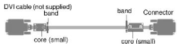
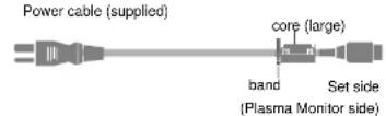
When you connect a computer to this monitor, attach the supplied ferrite cores. If you do not do this, this monitor will not conform to mandatory FCC standards.
Attaching the ferrite cores.
Set the ferrite cores on both ends of the DVI cable (not supplied), and at one end of the power cable (supplied).
Close the lid tightly until the clamps click.
To avoid damage and prolong operating life:
- Use only with 120V 50/60Hz AC power supply. Continued operation at line voltages greater than 120 Volts AC will shorten the life of the unit, and might even cause a fire hazard.
- Handle the unit carefully when installing it and do not drop.
- Set the unit away from heat, excessive dust, and direct sunlight.
- Protect the inside of the unit from liquids and small metal objects. In case of accident, unplug the unit and have it serviced by an authorized NEC Service Center.
- Do not hit or scratch the panel surface as this causes flaws on the surface of the screen.
- For correct installation and mounting it is strongly recommended to use a trained, authorized NEC dealer.
- As is the case with any phosnorhaced display like a CRT
Recommendations to avoid or minimize phosphor burn-in
Like all phosphor-based display devices and all other gas plasma displays, Plasma monitors can be susceptible to phosphor burn under certain circumstances. Certain operating conditions, such as the continuous display of a static image over a prolonged period of time, can result in phosphor burn if proper precautions are not taken. To protect your investment in this NEC plasma monitor, please adhere to the following guidelines and recommendations for minimizing the occurrence of image burn:
* Always enable and use your computer's screen saver function during use with a computer input source.
* Display a moving image whenever possible.
* Always power down the monitor when you are finished using it.
NEC has built-in several operating modes in your PlasmaSync PD Series monitor to help you reduce the likelihood of phosphor burn. These are called the AccuShield Phosphor Protection System. If the Plasmasync monitor is in long-term use or continuous operation, use the functions available in AccuShield to reduce the likelihood of perceptible phosphor burn or to diminish its perceptible effects if it occurs. See pages E-34, 42 and 43 for instructions on how to use the Orbiter, Low Brightness and Inverse RGB modes of AccuShield.
* Lower the Brightness and Contrast levels as much as possible without impairing image readability.
* Display an image with many colors and color gradations (ie. photographic or photo-realistic images).
* Create image content with minimal contrast between light and dark areas. For example white characters on black backgrounds. Use complementary or pastel colors whenever possible.
* Avoid displaying images with few colors and distinct, sharply defined borders between colors.
Contact NEC Technologies at 1-800-836-0655 for other recommended procedures that will best suit your particular application needs.
Contents
Important Information E-2
Contents....E-4
How to Attach Options to the Plasma Monitor E-5
Introduction E-6
Part Names and Functions E-7
Control Panel E-7
Terminal Panel E-8
Remote Control E-9 Operating Range for the Remote Control E-9
Operating Range for the Remote Control....E-5 Setup Procedure....E-10
Connections E-11
Wiring Diagram E-11
Connecting Your PC or IBM compatible E-12
Connecting Your Macintosh Computer E-13
Connections with Equipment that has a Digital Interface ....E-14
Connecting Your VCR E-15
Connecting Your DVD Player....E-16
Connecting Your Stereo Amplifier E-17
Basic Operation....E-18 Transition on the Main Power and Return to Standby Mark....E-19
Turning on the Main Power and Return to Standby Mode E-18
Turning On or Off the Power with the Remote Control E-18
Power Management Function E-19
Selecting a computer or video source E-19
Menu Operations (On-screen Menu)......E-20
Buttons Used in Menu Operations E-22
Operation of the Menu Screen E-22
Configuration Menu (CONFIG MENU) E-23
Audio Settings (SOUND) E-24
Picture Adjustments (VISUAL CONTROL) E-25
Auto Picture/Wide Screen Settings (AUTO PICTURE)....E-26
Clock Frequency/Clock Phase Adjustment, and RGB Mode Adjustment (AUTO PICTURE) E-26
Wide Screen Setting (WIDE MODE) E-27
Horizontal/Vertical Position Adjustments (H-POSITION and V-POSITION) E-28
Direct Adjustment....E-28
Menu Adjustments E-29
Input Selection (INPUT SELECT) E-30
Standard Settings (NORMAL)......E-31
Information Screen (DISPLAY MODE) E-32
Timer Settings (PRESENT TIME) E-33
Time Settings E-33
Timer Settings E-33
4-Screen/9-Screen Multiple System Settings (VIDEO WALL MENU).... E-35
Hawu Display Platform Adjustment /OSU LOCATION
How to Attach Options to the Plasma Monitor
You can attach your optional mounts or stand to the plasma monitor in one of the following two ways:
In the upright position.
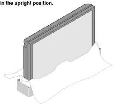
natural_image
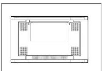
3D diagram of a rectangular panel mounted on a base with a folded paper underneath (no text or symbols)Lay the screen face down.
natural_image
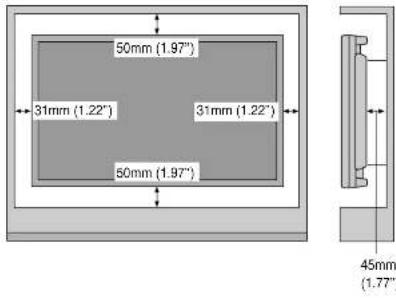
Top-down schematic of a rectangular room with four internal compartments and a central space (no text or symbols)Ventilation Requirements for enclosure mounting
To allow heat to disperse, leave space between surrounding objects as shown in the diagram to the right.
text_image
50mm (1.97") 31mm (1.22) 31mm (1.22) 50mm (1.97) 45mm (1.77)Pulling Out and Reinserting the Retractable Feet Notice:
See "Extending the Simple Feet" on page E-46.
* Installation of only the main unit is not possible. Be sure to use and install the main unit in conjunction with a stand or special unit.
NOTE: RETRACTABLE FEET ARE FOR TEMPORARY USE ONLY AND ARE NOT INTENDED FOR PERMANENT INSTALLATION.
MODEL # PX-42VPU1-ST STAND IS REQUIRED FOR PERMANENT TABLE-TOP INSTALLATION.
REPLACE THE FEET WHEN YOU MOVE THE MONITOR.
Introduction
OSM and IPM are trademarks of NEC Technologies, Inc. IBM PC/AT, PS/2, VGA, S-VGA, 8514/A and XGA are registered trademarks of International Business Machines Corporation. Apple and Macintosh are registered trademarks of Apple Computer, Inc. Microsoft is a registered trademark of Microsoft Corporation. Windows is a trademark of Microsoft Corporation.
Introduction to the PlasmaSync 50PD2
This section introduces you to your new PlasmaSync 50PD2, provides a list of materials that comes with your monitor and describes the features and controls.
The features you'll enjoy include:
* This unit can be used with IBM PC/AT, Macintosh, and compatibles.
(For details, see "Signal Identification For Raster Preset" Pg.E-62)
* Easy-to-operate remote control and external control connector.
* Wired/Wireless Remote Control PX-RC2U (optional) can be used as a wireless or as a wired remote control (with automatic switching by cable connection) and the remote THROUGH OUT connector permits simultaneous operation of multiple monitors.
(A maximum of 3 units can be connected.)
The external control connector with a THROUGH OUT feature permits various control functions to be made externally.
* ID No. settings can be made for up to 256 units.
* NTSC, PAL, SECAM, and M-NTSC composite video signals can be accommodated
Video signals from video cameras, video decks, video disc players, and other video equipment adhering to NTSC as well as PAL, SECAM, and M-NTSC (with a 4.43 MHz chroma signal) standards can be selected on screen.
* Varied set of input/output connectors
- Video input/output: BNC video connector, S-video connector. Each type is equipped with its own THROUGH OUT connector, single system.
- Analog RGB input: mini D-Sub 15-pin connector, BNC (G, B, R, H/CS, V connectors). BNC is equipped with its own THROUGH OUT connector, single custom.
* OSM (On Screen Manager) function
The OSM function displays a variety of screen adjustment and correction menus on the screen to allow fine settings to be made.
* Plug and Play compatible
Plug and Play supports VESA DDC1 and DDC level B. (VESA DDC1 and DDC2 level B)
The RGB3 input is compatible with DDC2 level B only.
* Can be used with RS-232C
^* IBM PC/AT is a registered trademark of International Business Machines Corporation.
* Macintosh is a registered trademark of Apple Computer, Inc.
^ VESA is a trademark of Video Electronics Standard Association.
* DVI is an abbreviation for Digital Visual Interface.
Contents of the Package
The following lists all of the items included in your plasma monitor package. Please save the original box and packing materials for future transportation or shipment of this monitor.
- Plasma monitor×1
- Power cable×1
- Wireless remote control × 1
- AA battery × 2
- Remote control holder × 1
- RGB signal cable
-
Stopper×2
-
Screw×2*
-
Ferrite core (large) × 1
-
Ferrite core (small)×2
-
User's manual × 1
* These are fittings for fastening the unit to a wall to prevent tipping due to external shock when using the stand (option). Fasten the safety fittings to the holes in the back of the monitor using the safety fitting mount screws.
Part Names and Functions
Control Panel

natural_image
Blank computer monitor screen with a circular button at the bottom right (no visible text or symbols on the screen)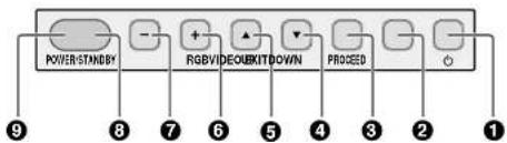
text_image
POWER/STANDBY RGBV/DECKITDOWN PROCED 9 8 7 6 5 4 3 2 1Part Names and Functions
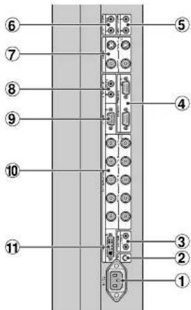
Terminal Panel
text_image
Diagram of a vertical electronic device with numbered components, likely an LCD panel or connector layout.
natural_image
Top-down architectural floor plan showing room layouts and structural elements (no text or labels)①AC IN connector
Connects with the supplied power cable.
②CONTROL LOCK
When "CONTROL LOCK" is set to "ON", the buttons on the set's front bezel control panel do not function.
③REMOTE (Mini jack)
IN lack: When you use the remote control with a wire, attach it
S-VIDEO IN connector (DIN 4 pin): Here is where you connect the S-video (Y/C separate signal).
* When connections are made to both the VIDEO connector and the S-VIDEO connector, the signal of the S video connector has priority.
S-VIDEO OUT connector (DIN 4 pin): You can use this connector to output the S-video signal from the S-VIDEO IN connector.
Part Names and Functions
Remote Control
text_image
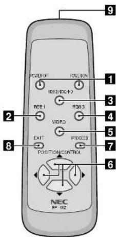
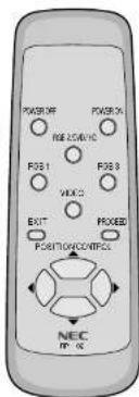
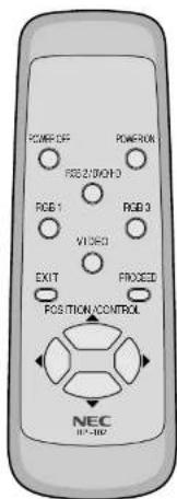
POSITION RGB 1 RGB 2 RGB 3 VIDEO EXIT PROCEED POSITION/CONTROL NEC RF-1021 POWER ON/OFF button
Switches the power on/off. See also page E-18.
* If the POWER/STANDBY lamp is not glowing, then these controls will not work.
2RGB 1 button
Select the RGB1 input. See also page E-19.
3RGB 2 button
Select the RGB 2/DVD/HD input. See also page E-19.
4 RGB 3 button
Select the RGB 3 input. See also page E-19.
5 VIDEO button
Select the VIDEO input. See also page E-19.
6 POSITION/CONTROL buttons
Adjust the image location horizontally and ver-
tically. See also pages E-22 and 28.
These buttons executes the menu selection and confirms adjustments/setting in the menu mode.
7 PROCEED button
Displays the on-screen menu (Menu mode). See also page E-22.
8 EXIT button
Exits the on-screen menu or Menu mode. See also page E-22.
9 Infrared transmitter
Direct the remote control toward the remote sensor on the plasma monitor. See also page E-9.
NOTE:
* The wired/wireless remote control PX-RC2U is available as an option.
In addition to the features on the supplied remote control, the optional remote control has the following functions:
- Direct remote button operation for picture adjustments such as contrast and brightness.
- Direct remote button operation for picture and alignment adjustments such as horizontal and vertical position.
- When the remote control is connected to the REMOTE IN jack with the remote cable, the optional remote control can be used as the wired remote control.
The REMOTE OUT connector is used to connect multiple plasma monitors together and allows all of the plasma monitors to be controlled by one remote control.
Setup Procedure
1 Determine the installation location
Installation of only the plasma monitor is not possible. Be sure to use and install the plasma monitor in conjunction with a stand or special unit.
| CAUTION | DO NOT ATTEMPT TO INSTALL THE PLASMA MONITOR. |
| Installing your plasma display must be done by a qualified technician. Contact your dealer for more information. | |
| CAUTION | DO NOT USE THE RETRACTABLE FEET FOR PURPOSE OF PERMANENT INSTALLATION. |
| The retractable feet are for temporary use only and are not intended for permanent installation. | |
| CAUTION | MOVING OR INSTALLING THE PLASMA MONITOR MUST BE DONE BY TWO OR MORE PEOPLE. |
| Failure to follow this caution may result in injury if the plasma monitor falls. | |
Important
Lay the protective sheet, which was wrapped around the plasma monitor when it was packaged, beneath the plasma monitor so as not to scratch the panel.
2 Install the plasma monitor
The connections of two or more plasma monitors may degrade image quality on the remaining connected units connected to the loop out. Consider the cable length or cable type to be used. Note that only one plasma monitor connection is possible for loop-out.
4 Connect external equipment (See page E-11)
• To protect the connected equipment, turn off the main power before making connections.
• Refer to your equipment user manual.
5 Connect the supplied power cable
- The power outlet socket should be installed as near to the equipment as possible, and should be easily accessible.
- Attach the supplied ferrite core to the power cable. See page E-47.
- Fully insert the prongs into the power outlet socket. Loose connection may cause noise.
• The maximum power consumption 570 W (the maximum current rating 6.0 A)
6 Switch on the power of all the attached external equipment
When connected with a computer, switch on the power of the computer first.
7 Operate the attached external equipment.
Display the signal on the external equipment you wish.
8 Select the input mode (See pages E-19 and 24)
Select the appropriate input.
Connections
Before making connections:
* First turn off the power of all the attached equipment and make connections.
* Refer to the user manual included with each equipment.
Wiring Diagram
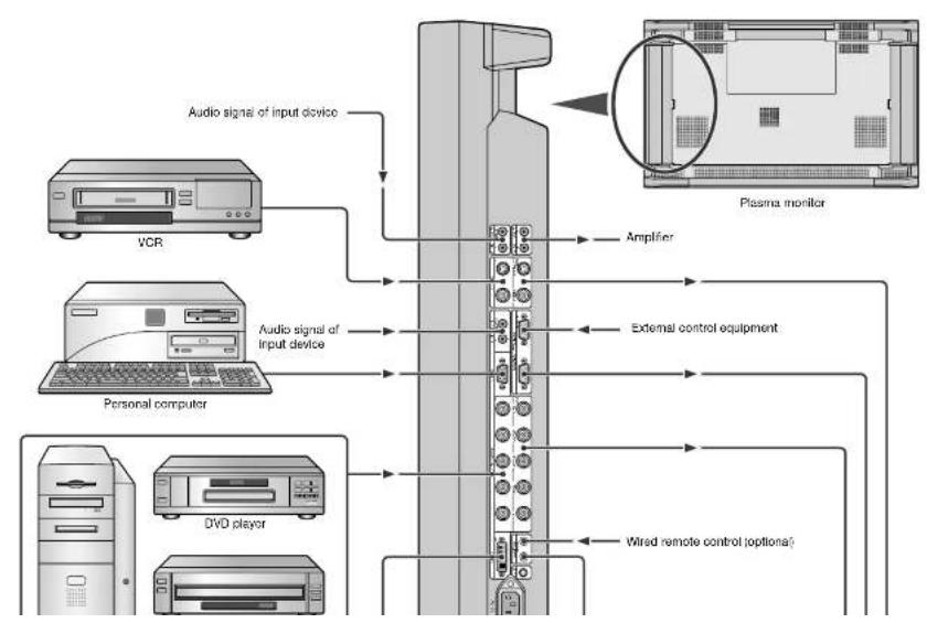
flowchart
graph TD
    A["Audio signal of input device"] --> B["Plasma monitor"]
    C["VCR"] --> B
    D["Personal computer"] --> B
    E["DVd player"] --> B
    F["Amplifier"] --> B
    G["External control equipment"] --> B
    H["Wired remote control (optional)"] --> B
Connections
Connecting Your PC or IBM compatible
Connecting your PC to your Plasma monitor will enable you to display your computer's screen image.
Some video cards may not display an image correctly.
If you wish to input wide signals, make the "RGB MODE" and "INPUT MODE" settings.
(See "Signal Identification For Raster Preset" on page E-62.)
Connect the Plasma Monitor to Your PC or IBM Compatible
- To connect the RGB 1 IN connector (mini D-sub 15 pin) on the plasma monitor, use the supplied RGB signal cable (mini D-sub 15 pin to mini D-sub 15 pin).
- To connect the RGB 2/DVD/HD IN connector (BNC) on the plasma monitor, use the optional signal cable (mini D-sub 15 pin to BNC x 5). Select [RGB] for RGB 2 from the INPUT SELECT menu.
When connecting one or more Plasma monitors, use the RGB 2/DVD/HD OUT connector (BNC). - The AUDIO IN 1 and 2 can be both used for audio input. For connection, select [INPUT 1] or [INPUT 2] from the SOUND menu.

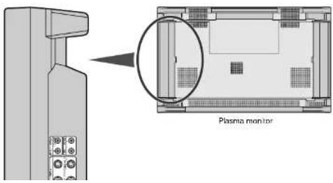
text_image
Plasma monitorConnecting Your Macintosh Computer
Connecting your Macintosh computer to your Plasma monitor will enable you to display your computer's screen image. Some video cards or drivers may not display images correctly. (See also "Signal Identification For Raster Preset" on page E-62.)
Connect the Plasma Monitor to Your Macintosh
• To connect the RGB 1 IN connector (mini D-sub 15 pin) on the plasma monitor, use the supplied RGB signal cable (mini D-sub 15 pin to mini D-sub 15 pin).
For older Macintosh, use a pin adapter for Macintosh (available separately) to connect to your Macintosh's video port.
The resolution modes that you can select are:
- 13" fixed mode - 16" fixed mode - 19" fixed mode
- To connect the RGB 2/DVD:HD IN connector (BNC) on the plasma monitor, use the signal cable available separately (mini D-sub 15 pin to BNC x 5).
Select [RGB] for [RGB 2] from the INPUT SELECT menu.
When connecting one or more Plasma monitors, use the RGB 2/DVD/HD OUT connector (BNC).
- If you use with a Macintosh PowerBook, set "Mirroring" to Off.
Refer to your Macintosh's owner's manual for more information about your computer's video output requirements and any special identification or configuring your monitor's image and monitor may require.
- The AUDIO IN 1 and 2 (both RCA) can be both used for audio input. For connection, select [INPUT 1] or [INPUT 2] from the SOUND menu.
text_image
Plasma monitorConnections
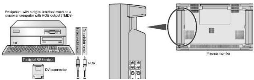
Connections with Equipment that has a Digital Interface
Connections can be made with equipment that is equipped with a digital interface compliant with the DVI (Digital Visual Interface) standard. If you wish to input wide signals, make the "RGB MODE" and "INPUT MODE" settings. (See "Signal Identification For Raster Preset" on page E-62.)
Connect the Plasma Monitor to a Computer with a Digital Output
• To connect the RGB 3 IN connector on the plasma monitor, use a DVI 29-pin signal cable (available separately).
• The RGB 3 IN connector also accepts a DVI 25-pin (digital only) cable.
- Input TMDS signals conforming to DVI standards.
• To maintain display quality, use a cable with a quality prescribed by DVI standards that is within 5 meters (6.6 feet) in length.
- Attach the supplied small ferrite cores to the DVI signal cable. See page E-47 for attaching the ferrite cores.
- The AUDIO IN 1 and 2 (both RCA) can be both used for audio input. For connection, select [INPUT 1] or [INPUT 2] from the SOUND menu.
text_image
Equipment with a digital interface such as a personal computer with RGB output (TMDS) To digital RGB output DVI connector To users the input RCA Plasma monitorConnecting Your VCR
Connecting your VCR or laser disc player to your Plasma monitor will enable you to display your VCR's or laser disc player's video. Refer to your VCR or laser disc player owner's manual for more information,
Connect the Plasma Monitor to a VCR or Laser Disc Player
• To connect the VIDEO IN connector (BNC) on the plasma monitor, use a separately available BNC connector cable. You will need a separately available BNC-to-RCA adapter to connect a VCR or laser disc player with an RCA pin jack to the BNC connector cable.
- When connecting one or more Plasma monitors, use the VIDEO OUT connectors (BNC).
- The AUDIO IN 1 and 2 (both RCA) can be both used for audio input. For connection, select [INPUT 1] or [INPUT 2] from the SOUND menu.
text_image
D/N 4 pin BNC RCA D/N 4 pin BNC Plasma monitorConnections
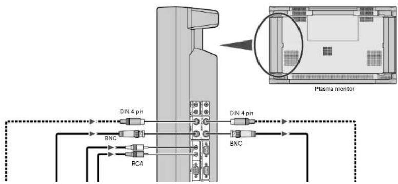
Connecting Your DVD Player
Connecting your DVD player to your Plasma monitor will enable you to display your DVD's video.
Refer to your DVD player owner's manual for more information.
* When a video filmed in frames per second (progressive) is played back, the plasma monitor takes the second and third frames, and converts them into a progressive signal with 60 frames per second. Note that only NTSC and 480i at 60 Hz is available.
Connect the Plasma Monitor to a DVD Player
- To connect the RGB 2/DVD/HD IN connector (BNC) on the plasma monitor, use a separately available BNC connector cable. You will need a separately available BNC-to-RCA adapter to connect a DVD player with an RCA pin jack to the BNC connector cable. Some DVD players may have different connectors such as Y,Cb/Pb, and Cr/Pr. Select [DVD/HD] for RGB 2 from the INPUT SELECT menu. When connecting one or more Plasma monitors, use the RGB 2/DVD/HD OUT connectors (BNC).
- The AUDIO IN 1 and 2 (both RCA) can be both used for audio input. For connection, select [INPUT 1] or [INPUT 2] from the SOUND menu.
text_image
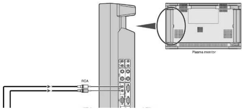
RCA Plasma monitorConnecting Your Stereo Amplifier
You can connect your stereo amplifier to your Plasma monitor. Refer to your amplifier owner's manual for more information.
Connect the Plasma Monitor to a Stereo Amplifier
- Turn on the plasma monitor and the amplifier only after all hookups have been made.
- Use an RCA cable to connect the AUDIO OUT connector (RCA) on the plasma monitor and the audio input on the amplifier.
- Do not reverse the audio left and right jacks.
• The AUDIO IN 1 and 2 (both RCA) can be both used for audio input. For connection, select [INPUT 1] or [INPUT 2] from the SOUND
menu.
• The AUDIO OUT jack outputs sound for the currently selected video.

text_image
RCA RCA Plasma monitorBasic Operation
Before operating the remote control, be sure to turn on the main power to the plasma monitor.
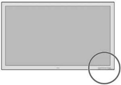
natural_image
Blank rectangular screen with a small circular highlight on the right side (no text or symbols)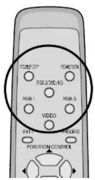
Turning on the Main Power and Return to Standby Mode
The plasma monitor enters the standby mode and the POWER/STANDBY lamp is lit in orange when the power cable is plugged into the wall outlet.
■ To turn the main power:
Press the POWER button on the front panel of the plasma monitor
The main power will be turned on. The POWER/STANDBY lamp is lit in green.
■ To turn off the power (standby mode):
Press the POWER button again
The plasma monitor is in standby mode. The POWER/STANDBY lamp is lit in orange.


Turning On or Off the Power with the Remote Control
■ To turn on the plasma monitor: Make sure that the POWER/STANDBY lamp is lit in orange (standby).
Press the POWER ON button on the remote control.
The plasma monitor is turned on. The POWER/STANDBY lamp is lit in green.

■ To turn off the plasma monitor: Press the POWER OFF button on the
■ POWER/STANDBY Lamp Status
| Status POWER/STANDBY lamp | ||
| Normal | Main Power ON | Green |
| Timer enabled | Orange flashing | |
| Power OFF with remote control | Orange | |
| Main Power Standby | Orange | |
| Error | Abnormal heat warning | Green flashing |
| Panel damaged | Green and/or Orange flashing | |
NOTE: In some cases the fan may stop running. This is not a malfunction.
Important
Notes on the POWER/STANDBY lamp on the plasma monitor
* The POWER/STANDBY lamp's flashing in alternately green and orange, or flashing in green only indicates that the plasma monitor detects an error. Should this happen, power off the plasma monitor immediately and contact your dealer:
When Using Power Management Function
This plasma monitor follows the VESA approved DPMS Power Management function.
The power management function is an energy saving function that automatically reduces the power consumption of the display when the keyboard or the mouse has not been used for a fixed period. The status of power management can be checked by POWER/STANDBY lamp display.
See page E-39.
Selecting a computer or video source
■ To view a video source:
Press the VIDEO button.
Displays the image from the equipment connected to the VIDEO IN connector.
• See page E-15 for connection.
■ To view the image from a computer, DVD player or HD laser disc player:
Select [RGB] or [DVD:HD] for RGB 2 from the INPUT SELECT menu.
Press the source button (RGB 1, RGB 2/DVD/HD, or RGB 3)
Displays the image from the computer, DVD player or HD laser disc player connected to the selected RGB input connector.
- You can select the source also by using the RGB button on the front panel.
To do this, each press of the RGB button selects [RGB 1] - [RGB 2] or [DVD/HD] - [RGB 3] in sequence.
• See page E-11 for connection.
NOTE:
* The default input is the last input used, but the plasma monitor can be configured to display either the last input used or a preset input whenever it is used turned on. (See "Power-On Mode Setting" on page E-37.)
During RGB3 mode the power management function is available in Off-state only. (This is Active-off Power state in DMPM of DVI standard.) An image will be displayed in 4 seconds after TMDS signal is returned.
Menu Operations (On-screen Menu)
Use of the on-screen menu (OSM) function allows the setting of a variety of detailed adjustments. The adjustment settings are retained even when the power is switched off.
The on-screen menu (OSM) function displays a menu on the screen from which the adjustments are made.
■ List of Setting Details
| Icon Configuration menu | Sub menu | Adjustment settings | Page | |
| (None) | CONFIG MENU (Configuration menu)To display this menu, press and hold the ▲ button and the PROCEED button at the same time for 3 seconds or longer on the remote control or the main unit. | OSD DISPLAYOSD MODEWIRELESS REMOTECONTROLSYNC MODEPLE LINKALL RESET | Sets whether or not the main menu is displayed.Sets whether or not the second screen of the main menu is displayed.Sets whether or not wireless transmission of the remote control is enabled.Sets the sync signals that will be automatically selected.Sets the brightness of the screen when there are multiple screens.Returns all adjustments and settings of CONFIG MENU to the factory default values. | E-23E-23E-23E-23E-23 |
Main Menu Page 1 Items
| Icon Main menu | Sub menu | Adjustment settings | Page | |
| SOUND(Audio settings) | VOLUMEBALANCEMUTEINPUT1INPUT2 | Volume adjustmentLeft-right balance adjustmentMute settingSets audio input to AUDIO IN 1Sets audio input to AUDIO IN 2 | E-24E-24E-24E-24E-24 | |
| VISUAL CONTROL(Picture adjustments) | BRIGHTNESSCONTRASTSHARPNESSCOLORTINT | Screen brightness adjustmentImage contrast adjustmentImage sharpness adjustmentAdjustment of color saturationTint adjustment | E-25E-25E-25E-25E-25 | |
| AUTO | AUTO PICTURE(Auto picture/Wide screen settings) | AUTO PICTUREINPUT MODERGB MODEWIDE MODE | Automatic adjustment of clock frequency/clock phaseThis is set when switching of input signal discrimination is required.Sets the mode (moving picture/still picture mode) to suit the input signal.WIDE MODE setting | E-26E-26E-26E-27 |
Menu Operations
Main Menu Page 2 Items
| Icon Main menu | Sub menu | Adjustment settings | Page | |
| [DXY] | (To Page 1) | Setting [OSD MODE] to [PRO] on the configuration menu displays the first page of the main menu. | ||
 | DISPLAY MODE (Information screen) | SOURCE INFO. Allows verification of the currently input signal (data). E-32 | ||
 | PRESENT TIME (Timer setting) | DATE | Sets the date. | E-33 |
| TIME | Sets the time. | E-33 | ||
| TIMER | Sets the "On'Off" time for switching the power and sets the input mode. | E-33 | ||
 | VIDEO WALL MENU Y-Screen WScreen Multiple Screen Settings | SCREEN DIVIDER | Sets the number of screens to be used to 1, 4, or 9 screens. | E-35 |
| POSITION | Sets the screen position. | E-35 | ||
| DISP MODE | Sets the display mode. | E-35 | ||
 | OSM LOCATION (Menu display position adjustments) | OSM H-POS | Menu display horizontal position adjustment | E-36 |
| OSM V-POS | Menu display vertical position adjustment | E-36 | ||
| OSM ANGLE | Sets the menu display as a horizontal or vertical screen. | E-36 | ||
| OSM DISPLAY TIME | Sets the menu display time. | E-36 | ||
 | OTHER SETTING (Other settings) | COLOR SYSTEM | Sets the color system (to AUTO, 3.58 NTSC, PAL, SECAM, or 4.43 NTSC). | F-37 |
| P-ON MODE | Sets the input mode that will be in effect when power is switched on. | E-37 | ||
| POWER MANAGER | Sets the power management function. | E-38 | ||
| SET ID NO | Sets ID numbers for up to 256 units. | E-40 | ||
| RGB3 ADJUST | Set when the RGB 3 image is not stable. | E-40 | ||
| CINEMA MODE | Sets the cinema mode. | E-41 | ||
| ALL RESET | Returns the settings of all other functions to the default values. | E-40 | ||
 | LONG LIFE MODE (Long Life settings) | LUM LIMIT ORBITTING | Limits screen brightness to reduce image burn in. | E-42 |
| Moves the screen at fixed intervals to reduce image burn-in. | E-42 | |||
| INV:WT | Displays an inverse (negative/positive) screen or an all-white image to reduce image burn-in. | E-42 | ||
| PROG. ORBIT | Programs the movement of screen dots to reduce burn-in. | E-42 | ||
| GRAY LEVEL | Adjusts the brightness of screen portions other than images appearing at the upper, lower, or left, right areas of the screen in NORMAL or other modes. | E-43 | ||
Buttons Used in Menu Operations
text_image
POWER REF 25/01C P08.1 P08.3 VINC EXIT FIXED POSITION/CONTROL NEC PP-16• PROCEED button
Displays the main menu.
Determine the selection or set details in the main menu and proceed to the next step.
- EXIT button
Turns off the main menu.
Press during display of the sub menu to return to the main menu.
• POSITION/CONTROL buttons
▲ button : Moves the cursor up.
▼ button : Moves the cursor down.
button : Moves the cursor left.
Press during display of the sub menu (setting/adjustment screen) to select selling items and also to decrease the adjustment value.
▶ button : Moves the cursor right
Press during display of the sub menu (setting/adjustment screen) to select setting items and also to increase the adjustment value.
NOTE:
CONFIG MENU
Press and hold the POSITION/CONTROL ▲ button and the PROCEED button simultaneously for 3 seconds or longer to display the CONFIG MENU. This only works for the CONFIG MENU out of the various on-screen menus (OSM).
The menu screen of the CONFIG MENU does not contain icons that indicate menu items; however, operation is the same as with other screens.
Operation of the Menu Screen
Main menu Sub menu
The main menu comprises 2 pages (screens). Place the cursor on icon ▶ or ▶ and use the POSITION/CONTROL TO BTR to change the page. (Set [OSD MODE] to [PRO] on the configuration menu before performing other operations.)

- Items of the main menu are displayed as icons. See Pages E-20 and 21 for details.
- Cursor
[Non-Text]
SHARPNESS
COLOR
TINT
...
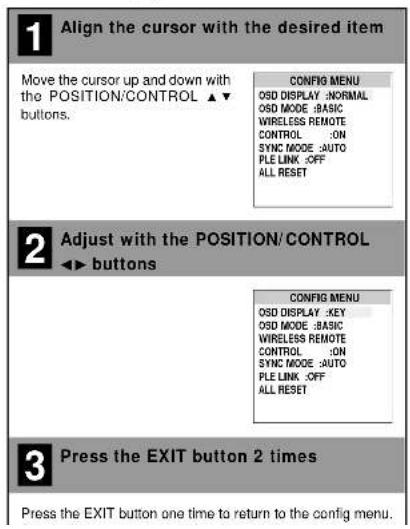
Configuration Menu (CONFIG MENU)
This menu sets the main menu, display of adjustment details, remote control, sync, and the brightness of the multiple system.
Preparation Simultaneously press and hold the POSITION/CONTROL ▲ button and the PROCEED button for 3 seconds or longer to display the menu screen.
text_image
1 Align the cursor with the desired item Move the cursor up and down with the POSITION/CONTROL ▲▼ buttons. 2 Adjust with the POSITION/CONTROL ◀▶ buttons 3 Press the EXIT button 2 times Press the EXIT button one time to return to the config menu.Adjustment Items
■ OSD DISPLAY
[NORMAL]: Displays the menu screen and adjustment details. [KEY]: Displays the adjustment details for only input switching and direct adjustments.
OFF: No display of any menu screens or adjustment details.
■ OSD MODE
[BASIC] : Allows only the first page of the main menu to be displayed. [PRO] : Allows Pages 1 and 2 of the main menu to be displayed.
■ WIRELESS REMOTE CONTROL
[ON] : Enables remote control wireless transmission. OFF : Disables remote control wireless transmission.
* This is normally [ON]. Set OFF to avoid unwanted control from other remote controls.
■SYNC MODE
[AUTO] : Automatically detects separate sync signals, green sync signal (i.e., sync-on-green), and composite sync signal.
[GSYNC] : Automatically detects green sync signal (i.e., sync-on-green).
[CSYNC] : Automatically detects composite sync signal.
■ PLE LINK
[ON] : Sets a uniform screen brightness for each screen in a 4-screen multiple system
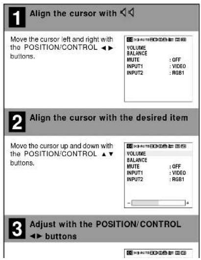
Audio Settings (SOUND)
This menu sets the volume, balance, mute, and selection of input.
Note that only sound of the currently displayed signal is output.
Preparation Press the PROCEED button to display the main menu.
text_image
1 Align the cursor with Move the cursor left and right with the POSITION/CONTROL ▶▶ buttons. VOLUME BALANCE MUTE : OFF INPUT1 : VIDEO INPUT2 : RGB1 2 Align the cursor with the desired item Move the cursor up and down with the POSITION/CONTROL ▶▼ buttons. VOLUME BALANCE MUTE : OFF INPUT1 : VIDEO INPUT2 : RGB1 3 Adjust with the POSITION/CONTROL ▶▶ buttons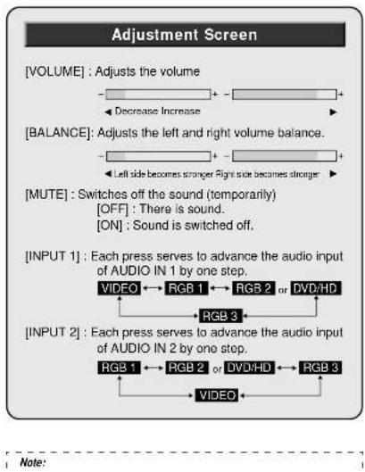
flowchart
graph TD
    A["VOLUME"] --> B["Adjusts the volume"]
    B --> C["Decrease Increase"]
    D["BALANCE"] --> E["Adjusts the left and right volume balance"]
    E --> F["Left side becomes stronger Right side becomes stronger"]
    G["MUTE"] --> H["Switches off the sound (temporarily)"]
    H --> I["OFF: There is sound."]
    H --> J["ON: Sound is switched off."]
    K["INPUT 1"] --> L["Each press serves to advance the audio input of AUDIO IN 1 by one step."]
    L --> M["VIDEO ↔ RGB 1 ↔ RGB 2 or DVD/HD"]
    N["INPUT 2"] --> O["Each press serves to advance the audio input of AUDIO IN 2 by one step."]
    O --> P["RGB 1 ↔ RGB 2 or DVD/HD ↔ RGB 3"]
    Q["Note:"] --> R["VIDEO"]
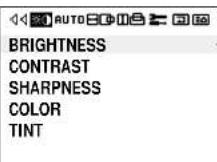
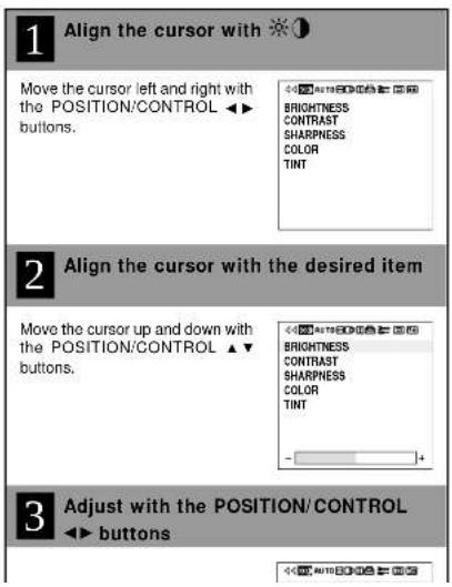
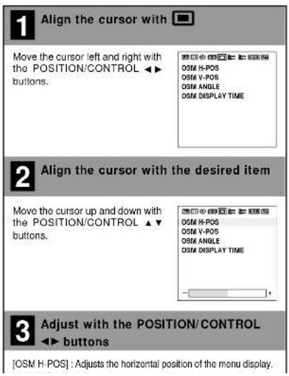
Picture Adjustments (VISUAL CONTROL)
This menu adjusts the brightness, contrast, sharpness, color, and tint.
Preparation Press the PROCEED button to display the main menu.
text_image
1 Align the cursor with ⚙① Move the cursor left and right with the POSITION/CONTROL ▶▶ buttons. BRIGHTNESS CONTRAST SHARPNESS COLOR TINT 2 Align the cursor with the desired item Move the cursor up and down with the POSITION/CONTROL ▶▼ buttons. BRIGHTNESS CONTRAST SHARPNESS COLOR TINT 3 Adjust with the POSITION/CONTROL ◀▶ buttonsAdjustment Screen
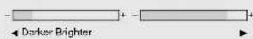
[BRIGHTNESS]: Adjusts the brightness of the screen.
[CONTRAST] : Adjusts the contrast of the image.
[SHARPNESS]: Adjusts the sharpness of the image.

[COLOR] : Adjusts the color saturation

[TINT] : Adjusts the tint.

* These adjustments will not be available when the color system setting is set to [PAL] or [SECAM].
Auto Picture/Wide Screen Settings (AUTO PICTURE)
Clock Frequency/ Clock Phase Adjustment, and RGB Mode Adjustment (AUTO PICTURE)
There is normally no need to adjust the clock frequency or clock phase when [AUTO PICTURE] is set to [ON]; however, when automatic adjustment cannot adjust the picture properly, a manual adjustment should be made.
Make an adjustment when a signal is newly input, and when vertical lines appear and the image appears blurred.
Preparation Press the PROCEED button to display the main menu.
text_image
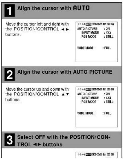
1 Align the cursor with AUTO Move the cursor left and right with the POSITION/CONTROL ▶▶ buttons. AUTO PICTURE : ON INPUT MODE : 4X3 RGB MODE : STILL WIDE MODE : FULL 2 Align the cursor with AUTO PICTURE Move the cursor up and down with the POSITION/CONTROL ▶▼ buttons. AUTO PICTURE : ON INPUT MODE : 4X3 RGB MODE : STILL WIDE MODE : FULL 3 Select OFF with the POSITION/CON- TROL ▶▶ buttons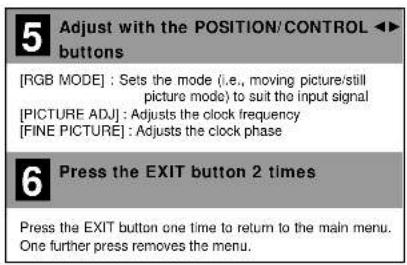
text_image
5 Adjust with the POSITION/CONTROL ▶▶ buttons [RGB MODE] : Sets the mode (i.e., moving picture/still picture mode) to suit the input signal [PICTURE ADJ] : Adjusts the clock frequency [FINE PICTURE] : Adjusts the clock phase 6 Press the EXIT button 2 times Press the EXIT button one time to return to the main menu. One further press removes the menu.Note:
■ AUTO PICTURE
Adjustment of [H-POSITION] and [V-POSITION] is not available when [AUTO PICTURE] is set to [ON] at the time of RGB signal input. When adjustment is required, set [AUTO PICTURE] to OFF.
When adjustment is required, set [AUTO PICTURE] to OFF. When the displayed image is small with respect to the original number of horizontal pixels (including instances where the display area, i.e., lit pixels is small), the picture may take up to 6 seconds to be displayed.
RGB MODE
[MOTION] : Set when a moving picture source is connected such as a scan converter.
[STILL] : Set when displaying a personal computer screen. INTM : Set when viewing a schema such as a digital hybrid device.
Wide Screen Setting (WIDE MODE)
This sets the wide screen display (to NORMAL, FULL, ZOOM, or STADIUM).
Preparation Press the PROCEED button to display the main menu.
1 Align the cursor with AUTO
Move the cursor left and right with the POSITION/CONTROL ◀▶ buttons.
AUTO PICTURE : OFF INPUT MODE : 4X3 RGB MODE : STILL
WIDE MODE
:FULL

2 Align the cursor with AUTO PICTURE
Move the cursor up and down with the POSITION/CONTROL ▲▼ buttons.
AUTO PICTURE : OFF INPUT MODE : 4X3 RGB MODE : STILL
WIDE MODE
:FULL
3 Set the wide screen mode with the POSITION/CONTROL ◀▶ buttons
[NORMAL]: This is the normal screen size (4:3).
Important
■ Precautions in Normal Mode
There are marked differences in brightness between the display portions and non-display portions (where there is no image) in [NORMAL] mode which result in image burn-in due to the strong contrast. In view of this, the following settings are strongly recommended.
Note that image burn-in will still occur, though somewhat later, even after making these settings and that burn-in cannot be suppressed. The monitor should be used in [FULL] mode as much as possible.
-
Perform gray level settings to narrow the differences in brightness between display and non-display portions of the image. (See P.E-43)
-
Weaken the image adjustment contrast and brightness. (See P.E-25)
- Perform the Long Life settings. (P.E-42)
Copyright
Please note that using this monitor for the purpose of commercial gain or the attraction of public attention in a venue such as a coffee shop or hotel and employing compression or expansion of the screen image with a wide screen setting (of FULL, ZOOM, or STADIUM) raises concern about the infringement of copyright rights which are protected by copyright law.
■ Screen Size and the Original Image
This monitor is equipped with a wide variety of wide screen settings. Selection of a screen size that differs with the image aspect ratio (i.e., the ratio of the vertical and horizontal dimensions of the screen) of the video tape or other software will produce differences in appearance with respect to the original image. Please keep this point in mind when selecting the screen size.
Horizontal/Vertical Position Adjustments (H-POSITION and V-POSITION)
Horizontal and vertical position adjustments are available in 2 types. "Direct adjustment" makes adjustments simply by pressing the buttons of the remote control and "Menu control adjustments" are made via menu display.
Direct Adjustment
Adjusts the horizontal position and the vertical position of the screen.
A press of the button displays the adjustment screen. Release your finger from the button after the adjustment is made. The display will disappear about 3 seconds later and the adjustment details will be stored.
Horizontal position adjustment (POSITION/CONTROL ◀▶)
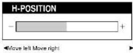
Vertical position adjustment (POSITION/CONTROL ▲▼)

text_image
POWER-OFF Power-RON RES2/VOH3 RGB 1 RGB 3 V1360 EXIT PROCEED POSITION/CONTROL NEC IP-180Horizontal/Vertical Position Adjustments (H-POSITION and V-POSITION)
Menu Adjustments
Horizontal position adjustment
Adjusts the horizontal position and width of the screen.
Preparation Press the PROCEED button to display the main menu.
Vertical position adjustment
Adjusts the vertical position and height of the screen.
Preparation Press the PROCEED button to display the main menu.
1 Align the cursor with
Move the cursor left and right with the POSITION/CONTROL ◀▶ buttons.
V-POSITION V-HEIGHT
- H-WIDTH is adjustable only in multiple mode.
1 Align the cursor with
Move the cursor left and right with the POSITION/CONTROL ◀▶ buttons.
V-POSITION V-HEIGHT
• V-HEIGHT is adjustable only in multiple mode.
2 Align the cursor with the desired item
Move the cursor up and down with the POSITION/CONTROL ▲▼ buttons.
H-POSITION H-WIDTH
2 Align the cursor with the desired item
Move the cursor up and down with the POSITION/CONTROL ▲▼ buttons.
V-POSITION V-HEIGHT
3 Adjust with the POSITION/CONTROL ◀▶ buttons
《XX AUTO Digital》
3 Adjust with the POSITION/CONTROL ◀▶ buttons
<< x3 auto ID 100
Input Selection (INPUT SELECT)
This performs RGB 2 input selection and sets the SCART jack.
Preparation Press the PROCEED button to display the main menu.

text_image
1 Align the cursor with Move the cursor left and right with the POSITION/CONTROL ▶▶ buttons. 2 Align the cursor with the desired item Move the cursor up and down with the POSITION/CONTROL ▶▼ buttons. 3 Adjust with the POSITION/CONTROL ▶▶ buttons •RGB 2Standard Settings (NORMAL)
This returns the audio settings (SOUND), image adjustment (VISUAL CONTROL), horizontal/vertical position (H-POSITION and V-POSITION), auto picture/wide screen settings (AUTO PICTURE), menu display position adjustment (OSM LOCATION), and color temperature adjustments (COLOR TEMP) to the default settings.
Preparation Press the PROCEED button to display the main menu.
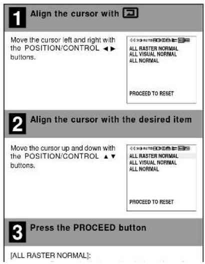
text_image
1 Align the cursor with Move the cursor left and right with the POSITION/CONTROL ▶▶ buttons. ALL RASTER NORMAL ALL VISUAL NORMAL ALL NORMAL PROCEED TO RESET 2 Align the cursor with the desired item Move the cursor up and down with the POSITION/CONTROL ▶▼ buttons. ALL RASTER NORMAL ALL VISUAL NORMAL ALL NORMAL PROCEED TO RESET 3 Press the PROCEED button [ALL RASTER NORMAL]:Note:
■ Functions that can be returned to the default settings
Information Screen (DISPLAY MODE)
This permits a check of the signal (data) that is currently being input.
Set [OSD MODE] to [PRO] on the configuration menu, then perform the following operations.
Preparation Press the PROCEED button to display the main menu.
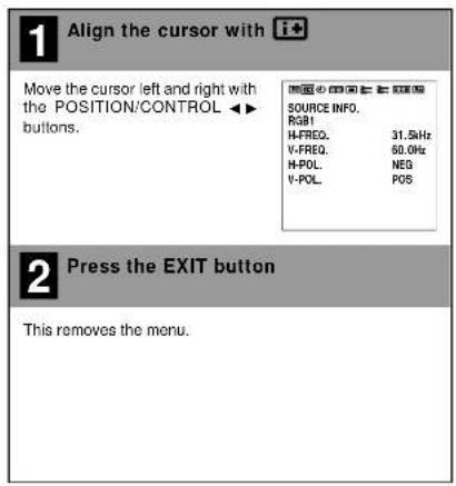
text_image
1 Align the cursor with i+ Move the cursor left and right with the POSITION/CONTROL ▶▶ buttons. SOURCE INFO. RGB1 H-FREQ. 31.5kHz V-FREQ. 60.0Hz H-POL NEG V-POL POS 2 Press the EXIT button This removes the menu.Note:
There is a slight error between the vertical frequency (V-FREQ.) displayed on the information screen and the actual vertical frequency of the con-
Information Screen
■ When RGB input is selected
[SOURCE INFO.]:
RGB 1, RGB 2, RGB 3,
DVD:HD
[H-FREQ.]: Horizontal frequency (kHz)
[V-FREQ.]: Vertical frequency (Hz)
polarity of horizontal
sync signal
NEG (Negative)
POS (Positive)
[V-POL.]: Polarity of vertical sync
signal
NEG (Negative)
POS (Positive)
1 Note:
(NO SIGNAL) is displayed when no signal is present.
■ When VIDEO input is selected
[SOURCE INFO.]
VIDEO. SCART
[MODE] : Color system standard
NTSC, PAL, SECAM
图 10
SOURCE INFO.
RGB1 H-FRE0 31.5kHz
V-FREQ 60.0Hz
H-PCL NEG
V-POL. POS
西区小田口二三四五
SOURCE INFO.
VIDEO
MODE : NTSC
Timer Settings (PRESENT TIME)
Time Settings
This sets the date and time.
Set [OSD MODE] to [PRO] on the configuration menu, then perform the following operations.
Preparation Press the PROCEED button to display the main menu.
1 Align the cursor with ⓘ
Move the cursor left and right with the POSITION/CONTROL ◀▶ buttons.
PRESENT TIME DATE: 2001. AUG. 10 TIME: 22:30 SET
TIMER:OFF
2 Align the cursor with AUTO PICTURE
Move the cursor as indicated below using the POSITION/CONTROL ▲▼ buttons. [Year] → [Month] → [Day] → [Hour] → [Minute]
PRESENT TIME DATE: 2001, AUG. 10 TIME: 22:30 SET
TIMER:OFF
3 Set the numerical values with the POSITION/CONTROL ◀▶ buttons
• Range of date and time settings
Timer Settings
This sets the date and time at which the power will be switched ON/OFF as well as the input mode.
Set [OSD MODE] to [PRO] on the configuration menu, then perform the following operations.
Preparation Press the PROCEED button to display the main menu.
1 Align the cursor with ⓘ
Move the cursor left and right with the POSITION/CONTROL ◀▶ buttons.
PRESENT TIME DATE: 2001, AUG. 10 TIME: 22:30 SET
TIMER : OFF
2 Align the cursor with TIMER
Move the cursor up and down with the POSITION/CONTROL ▲▼ buttons.
PRESENT TIME DATE: 2001. AUG. 10 TIME: 22:30 SET
TIMER : OFF PRESS 'PROCEED' FOR PROGRAM MENU
3 Turn the TIMER ON and OFF with the POSITION/CONTROL ◀▶ buttons
Each press of the POSITION/
[Non-Text]
5 Select the input method with the POSITION/CONTROL ▲▼ buttons, then press the EXIT button
[ DIRECT ] : Sets the desired date.
[ DAILY ] : Sets daily.
[WEEKLY]: Sets weekly.
无法识别
-
DIRECT
-
DAILY
-
WEEKLY
•DAILY
An asterisk "*" is displayed after the date.
WEEKLY
Selects the week day.
[MON] (Monday), [TUE] (Tuesday), [WED] (Wednesday), [THU] (Thursday), [FRI] (Friday), [SAT] (Saturday), [SUN] (Sunday)
An asterisk " * " is displayed after the week.
6 Align the cursor with the desired item
Move the cursor to the various items
with the POSITION/CONTROL ▲▼
◀▶ buttons.
图 4-10
PROGRAM MENU
DATE ON OFF MODE
OCT30 10:10 13:00 VIDEO JANDI 22:15 24:00 INV
JANDY 22:15 24:00 TNY MON* 15:45 19:00 VIDEO
WED* 09:00 11:00 RGB1
THU* 09:15 10:00 RGB2
13:30 14:30 VIDEO
21:00 22:00 RGB1
* [INV] produces an inverse (negative/positive) display of the screen to reduce image burn-in. The input mode at this time becomes that of the last input selected.
* [WT] produces an all-white screen display to reduce burn-in.
• [RP] provides operation according to the repeat program setting.
* [RI] provides operation according to the repeat program and [INV] settings.
- Repeat Program Setting
You can program to repeat switching screens within preset time.
Moving the cursor to [RP] or [RI] displays the Repeat Program Setting screen.
See the following for various settings,
(1) The power is switched ON when [ON TIME] is reached.
(2) The screen of [MODE 1] is displayed for the duration of [TIME 1].
(3) The screen of [MODE 2] is displayed for the duration of [TIME 2].
(4) Steps (2) and (3) are repeated until [OFF TIME] is reached.
(5) The power is switched OFF when [OFF TIME] is reached.
Press the EXIT button one time to return to the sub menu.
图 10
MODE SELECT MENU
MODE :RP
REPEAT PROGRAM
MODE1 :VIDEO
TIMET : 1 MIN
Only this monitor offers a system of 4 or 9 screens.
This menu sets the screen mode (from among 1, 4, or 9 screens) as well as the position.
See the Signal Identification For Raster Preset on Page E-62 for information about supported signals.
Set [OSD MODE] to [PRO] on the configuration menu, then perform the following operations.
Preparation Press the PROCEED button to display the main menu.
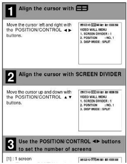
text_image
1 Align the cursor with Move the cursor left and right with the POSITION/CONTROL ▶▶ buttons. VIDEO WALL MENU 1. SCREEN DIVIDER : 1 2. POSITION : NO. 1 3. DISP MODE : SPLIT 2 Align the cursor with SCREEN DIVIDER Move the cursor up and down with the POSITION/CONTROL ▶▼ buttons. VIDEO WALL MENU 1. SCREEN DIVIDER : 1 2. POSITION : NO. 1 3. DISP MODE : SPLIT 3 Use the POSITION/CONTROL ▶▶ buttons to set the number of screens [1] : 1 screen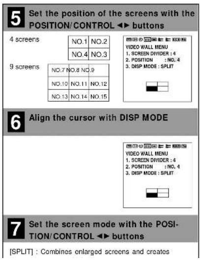
text_image
5 Set the position of the screens with the POSITION/CONTROL ▶ buttons 4 screens NO.1 NO.2 NO.4 NO.3 9 screens NO.7 NO.8 NO.9 N0.10 NO.11 NO.12 N0.13 NO.14 NO.15 6 Align the cursor with DISP MODE 7 Set the screen mode with the POSITION/CONTROL ▶ buttons [SPLIT] : Combines enlarged screens and createsMenu Display Position Adjustment (OSM LOCATION)
This sets the display position of the menu and the display format (landscape or portrait) as well as the display time. Set [OSD MODE] to [PRO] on the configuration menu, then perform the following operations.
Preparation Press the PROCEED button to display the main menu.
text_image
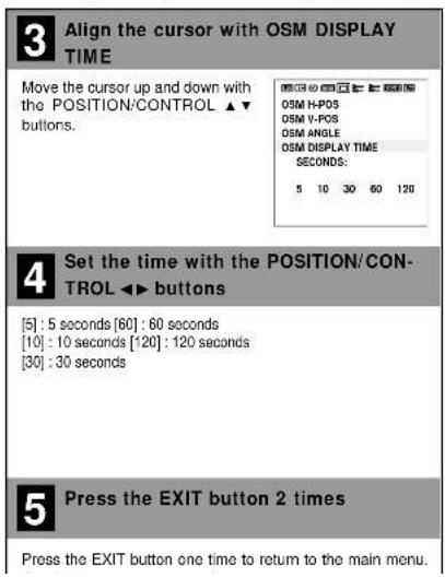
1 Align the cursor with Move the cursor left and right with the POSITION/CONTROL ▶▶ buttons. 2 Align the cursor with the desired item Move the cursor up and down with the POSITION/CONTROL ▶▼ buttons. 3 Adjust with the POSITION/CONTROL ◀▶ buttons [OSM H-POS] : Adjusts the horizontal position of the menu display.When the OSM DISPLAY TIME has been selected (Display Time Setting)
This function permits setting the time until the menu display is automatically deleted (in the absence of input operations).
text_image
3 Align the cursor with OSM DISPLAY TIME Move the cursor up and down with the POSITION/CONTROL ▲▼ buttons. OSM H-POS OSM V-POS OSM ANGLE OSM DISPLAY TIME SECONDS: 5 10 30 60 120 4 Set the time with the POSITION/CON- TROL ▶▶ buttons [5] : 5 seconds [60] : 60 seconds [10] : 10 seconds [120] : 120 seconds [30] : 30 seconds 5 Press the EXIT button 2 times Press the EXIT button one time to return to the main menu.Other Functions (OTHER SETTINGS)
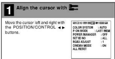
Color System Settings (COLOR SYSTEM)
This function sets the color system (to AUTO, 3.58 NTSC, PAL, SECAM, or 4.43 NTSC).
Set [OSD MODE] to [PRO] on the configuration menu, then perform the following operations.
Preparation Press the PROCEED button to display the main menu.
1 Align the cursor with 3
Move the cursor left and right with the POSITION/CONTROL ◀▶ buttons.
COLOR SYSTEM : AUTO P-ON MODE : LAST MEM POWER MANAGER : OFF SET ID NO : ALL RGB3 ADJUST : 1 CINEMA MODE : ON ALL RESET
2 Align the cursor with COLOR SYSTEM
Move the cursor up and down with the POSITION/CONTROL ▲▼ buttons.
COLOR SYSTEM : AUTO P-ON MODE : LAST MEM POWER MANAGER : OFF SET ID NO : ALL RGB3 ADJUST : 1 CINEMA MODE : ON ALL RESET
3 Set the color system with the POSITION/CONTROL ◀▶ buttons
[AUTO] : Automatically detects the color system and se
Power-On Mode Setting (P-ON MODE)
This function sets the input mode at the time the power is switched on.
Set [OSD MODE] to [PRO] on the configuration menu, then perform the following operations.
Preparation Press the PROCEED button to display the main menu.
1 Align the cursor with
Move the cursor left and right with the POSITION/CONTROL ◀▶ buttons.

2 Align the cursor with P-ON MODE
Move the cursor up and down with the POSITION/CONTROL ▲▼ buttons.

3 Set the P-ON MODE with the POSITION/CONTROL ◀▶ buttons
The mode that is displayed will be as indicated below accord
Power Management Settings (POWER MANAGER)
This sets the functions that serve to automatically reduce power consumption.
Set [OSD MODE] to [PRO] on the configuration menu, then perform the following operations.
Preparation Press the PROCEED button to display the main menu.
4 Press the EXIT button 2 times
Press the EXIT button one time to return to the main menu. One further press removes the menu.
* Aligning the cursor with [ALL RESET] and pressing the PROCEED button will return all the settings of the other functions to the default settings.
1 Align the cursor with
Move the cursor left and right with the POSITION/CONTROL ◀▶ buttons.
COLOR SYSTEM : AUTO P-ON MODE : LAST MEM POWER MANAGER : OFF SET ID NO : ALL RGB3 ADJUST : 1 CINEMA MODE : ON ALL RESET
2 Align the cursor with POWER MANAGER
Move the cursor up and down with the POSITION/CONTROL ▲▼ buttons.
COLOR SYSTEM : AUTO P-ON MODE : LAST MEM POWER MANAGER : OFF SET ID NO : ALL RGB3 ADJUST : 1 CINEMA MODE : ON ALL RESET
3 Set the power management mode with the POSITION/CONTROL ◀▶ buttons
[ON] : Power management function operates.
POWER/STANDBY Indicator
The status of the power management function can be checked with the POWER/STANDBY indicator of the monitor.
| Power Management Mode | POWER/STANDBY Indicator | Power Management Operation Status | Details | Recovery Method |
| On State | Green | Not operating | Horizontal/vertical sync signals are being input from the personal computer. | Not required since the personal computer is normally being used at this time. |
| Standby State | Yellow | Operating | Horizontal sync signal is not being input from the personal computer. | Press a keyboard key or move the mouse. The screen will be displayed immediately. |
| Suspend State | Orange | Operating | Vertical sync signal is not being input from the personal computer. | Press a keyboard key or move the mouse. The screen will be displayed; however, it will take some time from the standby state until the screen is displayed. |
| Off State | Orange | Operating | Horizontal/vertical sync signals are not being input from the personal computer. | Press a keyboard key or move the mouse. The screen will be displayed; however, it will take some time from the standby state until the screen is displayed. |
Other Functions (OTHER SETTINGS)
ID Number Setting (SET ID NO)
When using more than one of these monitors, this function sets ID numbers so that operation of the remote control does not cause multiple monitors to operate at the same time.
(These ID numbers can also be used for control with RS-232C.) The optional remote control is required to operate the plasma monitors for each ID number independently. (These ID numbers also need to be assigned.) Set [OSD MODE] to [PRO] on the configuration menu, then perform the following operations.
Preparation Press the PROCEED button to display the main menu.
text_image
1 Align the cursor with Move the cursor left and right with the POSITION/CONTROL ▶▶ buttons. COLOR SYSTEM : AUTO P-ON MODE : LAST MEM POWER MANAGER : OFF SET ID NO : ALL R583 ADJUST : 1 CINEMA MODE : ON ALL RESET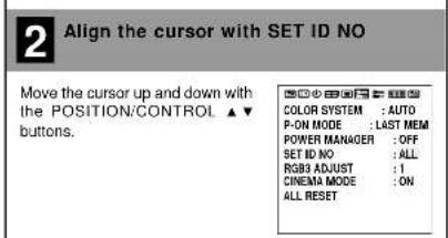
text_image
2 Align the cursor with SET ID NO Move the cursor up and down with the POSITION/CONTROL ▲▼ buttons. COLOR SYSTEM : AUTO P-ON MODE : LAST MEM POWER MANAGER : OFF SET ID NO : ALL RGB3 ADJUST : I CINEMA MODE : ON ALL RESETRGB 3 Adjustment (RGB 3 ADJUST)
Adjust this setting when the RGB 3 image is not stable. Set [OSD MODE] to [PRO] on the configuration menu, then perform the following operations.
Preparation Press the PROCEED button to display the main menu.
text_image
1 Align the cursor with Move the cursor left and right with the POSITION/CONTROL ▶ buttons. COLOR SYSTEM : AUTO P-ON MODE : LAST MEM POWER MANAGER : OFF SET ID NO : ALL ROSET ADJUST : 1 CINEMA MODE : ON ALL RESET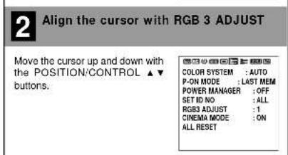
text_image
2 Align the cursor with RGB 3 ADJUST Move the cursor up and down with the POSITION:CONTROL ▲▼ buttons. COLOR SYSTEM :AUTO P-ON MODE :LAST MEM POWER MANAGER :OFF SET ID NO :ALL RGB3 ADJUST :1 CINEMA MODE :ON ALL RESET
Other Functions (OTHER SETTINGS)
Cinema Mode Setting (CINEMA MODE)
This function sets the cinema mode according to video information included on a DVD. This function is available on NTSC and 480I (60Hz) signals only. Set [OSD MODE] to [PRO] on the configuration menu, then perform the following operations.
Preparation Press the PROCEED button to display the main menu.
1 Align the cursor with
Move the cursor left and right with the POSITION/CONTROL ◀▶ buttons.
COLOR SYSTEM : AUTO P-ON MODE : LAST MEM POWER MANAGER : OFF SET ID NO : ALL RGB3 ADJUST : 1 CINEMA MODE : ON ALL RESET
2 Align the cursor with CINEMA MODE
Move the cursor up and down with the POSITION/CONTROL ▲▼ buttons.
COLOR SYSTEM : AUTO P-ON MODE : LAST MEM POWER MANAGER : OFF SET ID NO : ALL RGBS ADJUST : 1 CINEMA MODE : ON ALL RESET
3 Set the cinema mode with the POSITION/CONTROL ◀▶ buttons
[ON] : Detects whether a DVD source was based on
Note:
■ What Is CINEMA MODE?
This is a mode to output DVD video information in a progressive signal format.
CINEMA MODE
- [OM]
Normally set to [ON]. This setting detects whether a DVD source was based on film or video. When it was based on film, it will be progressively displayed in the appropriate method.
• OFF
This setting is used for video source on DVD, converting into the progressive output.

Long Life Settings (LONG LIFE MODE)
Long Life Settings (LONG LIFE MODE)
These settings reduce screen burn-in.
Set [OSD MODE] to [PRO] on the configuration menu, then per-
form the following operations.
Preparation Press the PROCEED button to display the main menu.

Align the cursor with

Move the cursor left and right with the POSITION/CONTROL ◀▶ buttons.
LONG LIFE MODE LUM. LIMIT : OFF ORBITTING : OFF INV / WT : OFF PROG. ORBIT ...... GRAY LEVEL : 3 ALL RESET

Align the cursor with the desired item
Move the cursor up and down with the POSITION/CONTROL ▲▼ buttons.
[LUM. LIMIT]
Suppresses the brightness of the screen.
[ORBITING]:
Moves the screen at a fixed period.
* Cannot be set at the time of the 4-screen/9-screen multiple system setting.
[INV/WT]:
Displays a negative/positive inverse image or an all-white screen.
LONG LIFE MODE LUM. LIMIT : OFF ORBITTING : OFF INV / WT : OFF PROG. ORBIT ...... GRAY LEVEL : 3 ALL RESET

Set the long life mode with the POSITION/CONTROL ◀▶ buttons
[LUM. LIMIT] and [ORBITING] settings
[ON] : Long life function is operational.
[INV/WT] settings
[INV] : Provides the negative/positive inverse image of the screen.
[WT] : Displays an all-white screen.
[PROG. ORBIT...→] settings
[SET]: [ON]: Function is operational.
[H-DOT]
Moves from 1 to 20 dots in the horizontal direction.
[V-LINE]
Moves from 1 to 20 dots in the vertical direction.
[TIME]
A 1- to 5-minute interval between movements.

Press the EXIT button 2 times
Press the EXIT button one time to return to the main menu.
Gray Level Settings (GRAY LEVEL)
In [NORMAL] and other modes, this adjusts the brightness of non-image portions that appear at top, bottom, left, or right of the screen.
Set [OSD MODE] to [PRO] on the configuration menu, then perform the following operations.
Preparation Press the PROCEED button to display the main menu.
1 Align the cursor with

Move the cursor left and right with the POSITION/CONTROL ◀▶ buttons.
LONG LIFE MODE LUM. LIMIT : OFF ORBITTING : OFF INV / WT : OFF PROG. ORBIT ...... GRAY LEVEL : 3 ALL RESET
2 Align the cursor with the desired item
Move the cursor up and down with the POSITION/CONTROL ▲▼ buttons.
LONG LIFE MODE LUM. LIMIT : OFF ORBITTING : OFF INV : WT : OFF PROG. ORBIT ...... GRAY LEVEL : 3 ALL RESET
3 Set the gray level with the POSITION/CONTROL ◀▶ buttons
Important
Gray Level Settings
The gray level can be set to suit the level of gray brightness desired by the user.
There are marked differences in brightness between the display portions and non-display portions (where there is no image) in [NORMAL] mode which result in image burn-in due to strong contrast. In view of this, the following settings are strongly recommended.
Note that image burn-in will still occur, though somewhat later, even after making these settings and that burn-in cannot be suppressed. The monitor should be used in [FULL] mode as much as possible.
-
Perform gray level settings to narrow the differences in brightness between display and non-display portions of the image.
-
Weaken the image adjustment contrast and brightness. (See P.E-25)
- Perform the Long Life settings. (P.E-42)

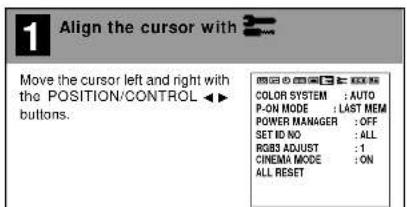
Color Temperature Adjustment (COLOR TEMP)
This adjusts the tone of white.
Set [OSD MODE] to [PRO] on the configuration menu, then per-
form the following operations.
Preparation Press the PROCEED button to display the main menu.

text_image
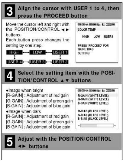
1 Align the cursor with RGB Move the cursor left and right with the POSITION/CONTROL ▶▶ buttons. COLOR TEMP 2 Align the cursor with COLOR TEMP Move the cursor up and down with the POSITION/CONTROL ▶▼ buttons. COLOR TEMP HIGH LOW USER1 3 Make the setting with the POSITION/CONTROL ▶▶ buttons [HIGH] : Produces a white with a strong blue content.When User 1 to 4 Has Been Selected (User Settings)
Permits a detailed adjustment of the white balance. Allows storage of adjustment values from 1 to 4.
text_image
3 Align the cursor with USER 1 to 4, then press the PROCEED button Move the cursor left and right with the POSITION/CONTROL ▶ buttons. Each button press changes the setting by one step. HIGH ← LOW ← USER 1 USER 4 ← USER 3 ← USER 2 COLOR TEMP HIGH LOW USER1 PRESS 'PROCEED' FOR GAIN / BIAS SETTING 4 Select the setting item with the POSITION/CONTROL ▶ buttons • Image when bright [R-GAIN] : Adjustment of red gain [G-GAIN] : Adjustment of green gain [B-GAIN] : Adjustment of blue gain • Image when dark [R-GAIN] : Adjustment of red gain [G-GAIN] : Adjustment of green gain [B-GAIN] : Adjustment of blue gain 5 Adjust with the POSITION/CONTROL ▶ buttonsAppendix
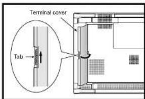
Opening the Terminal Cover
When connecting signal or other cables, the terminal cover of the monitor terminal section is opened to allow the connection to be made. After making the connection, close the terminal cover to permit cables to be arranged.
text_image
Terminal cover Tab1 Raise the tab at the side of the terminal cover and open the terminal cover at the same time.
2 Release the tab.
Closing the Terminal Cover
1 Raise the tab at the side of the terminal cover and close the terminal cover at the same time.
2 Release the tab.
Removing the Terminal Cover
When connecting signal or other cables, it may not be possible to close the terminal cover of the monitor terminal section. Should this be the case, the terminal cover can be removed for ease of use.

text_image
Mounting portion Terminal coverAttaching the Terminal Cover
1 Lift the mounting portion at the top of the terminal cover and remove the terminal cover at the same time.
1 Insert the mounting portion at the bottom of the terminal cover.
2 Lift the top portion of the terminal cover and insert at the same time.
Appendix
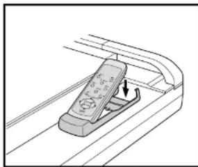
Placing the Remote Control into the Remote Control Holder
The remote control can be stored away in the remote control holder when not in use.
natural_image
Diagram of a remote control device with an arrow indicating the left side (no text or symbols present)1 Insert the bottom portion of the remote control into the bottom portion of the remote control holder.
2 Insert the upper portion of the remote control into the upper portion of the remote control holder. (Insert until an engagement click is heard.)
Removing the Remote Control
1 Lift the upper portion of the remote control.
2 Disengage the lower part of the remote control from the remote control holder.
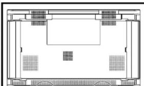
Extending the Simple Feet
Simple feet are housed in the lower portion of the monitor for temporary placement and for servicing. They will be convenient when the time comes to set down the monitor or move it.
natural_image
Architectural floor plan showing room layouts and structural elements (no text or labels)1 Grasp and pull out the ends of the simple feet which are housed in the bottom portion of the monitor.
2 The simple feet will open automatically when your hand is removed.
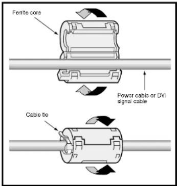
Attaching the Ferrite Cores
Attach the ferrite cores to the power cable and the DVI signal cable.
Use of the cables without mounting the ferrite cores will result in the occurrence of noise.
text_image
Fertite core Power cable or DVI signal cable Cable tie1 Open the ferrite cores and clamp them on the power cable and the DVI signal cable.
2 Close the ferrite cores.
3 Fix the ferrite cores in place with cable ties so that they do not shift.
Mounting Positions of Ferrite Cores and Cable Ties
Attach the large ferrite core at the end of the power cable that is close to the monitor.
Attach one small ferrite core to each end of the DVI signal cable.
■ Power cable
Ferrile core (Large)
Appendix
Pin Configuration and Signal Level of Mini D-Sub 15-Pin (Analog) Input Connector
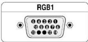
Signal level
VIDEO signal : 0.7Vp-p (Analog)
Sync signal : TTL level
| Pin No. Signal (Analog) | |
| 1 Red | |
| 2 Green or sync-on-green | |
| 3 Blue | |
| 4 Ground | |
| 5 Ground | |
| 6 Red ground | |
| 7 Green ground | |
| 8 Blue ground | |
| 9 No connection | |
| 10 Sync signal ground | |
| 11 Ground | |
| 12 Bi-directional DATA (SDA) | |
| 13 Horizontal or composite sync | |
| 14 Vertical sync | |
| 15 Data clock | |
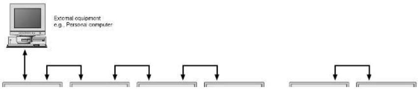
Pin Configuration and Functions of External Control Connector (Mini D-Sub 9 - Pin)
Application
These specifications are applicable to NEG plasma monitors (including 42- and 50-inch types) and communications control from external equipment.
Connections
Connections should be made as described below.
flowchart
graph TD
    A["External equipment e.g. Personal computer"] --> B["Computer"]
    B --> C["Data Structure 1"]
    B --> D["Data Structure 2"]
    B --> E["Data Structure 3"]
    B --> F["Data Structure 4"]
    B --> G["Data Structure 5"]
Appendix
Communication Parameters
(1) Communication system Asynchronous
(2) Interface RS-232C
(3) Baud rate 9600 bps
(4) Data length 8 bits
(5) Parity Odd
(6) Stop bit 1 bit
(7) Communication code Hex
Communication Format
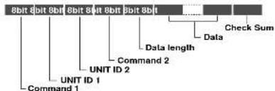
text_image
8bit 8bit 8bit 8bit 8bit 8bit Data length Data Check Sum Command 2 UNIT ID 2 UNIT ID 1 Command 1Command 1
Together with Command 2, this is a number that distinguishes the various commands.
For ACK, when bit 2 and bit 3 are both "1", reception of a supported command or data is indicated. When bit 2 is "0", reception of an unsupported command or data is indicated.
Bit 0 and bit 1 should be set as described below.
| bit0 | bit1 | |
| 0 | 0 | When multiple screens are selected |
| 0 | 1 | Not used |
| 1 | 0 | At time of set ID selection |
| 1 | 1 | At time of regular use |
* When normally selecting one screen, ID or multiple screen(VIDEO WALL), set bit 0 and bit 1 of Command 1.
Example: CFH for powering on
(Command 1)
CFH→1111 1111 (CFH): At time of regular use
1111 1110 (CEH): Not used
Check Sum (CKS), Error Processing, and ACK
1) Checks that received data incorporates both the following checksum and RS-232C (odd) parity.
The checksum comprises the following aspects of one transmitted or received frame: Command 1, Unit 1 and 2, Command 2, data length, and the lower order 8 bits of the total data.
Check Sum Example
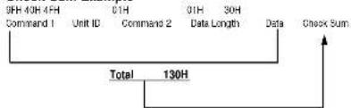
flowchart
graph TD
    A["9FH 40H 4FH"] --> B["Command 1"]
    C["01H"] --> D["Unit ID"]
    E["01H"] --> F["Command 2"]
    G["30H"] --> H["Data Length"]
    I["Data"] --> J["Check Sum"]
    K["Total"] --> L["130H"]
    L --> M["Output"]
2) Error Processing
(1) When the communications interval is 4 ms or greater, the arrival of a subsequent Command 1 will be recognized. If meaningful data cannot be discerned at this time, that data will not be recognized.
(2) When the receive data error, checksum error, and the receive data could not all be taken in, ACK is not returned.
3) Returning an ACK
When command processing exceeds 0.5 seconds following command reception, an ACK1 for which bit 3 of Command 1 has been set to "0" (during command processing) is returned every 0.5 seconds until command processing is completed. When command processing is completed, an ACK2 for which bit 3 of Command 1 has been set to "1" (at the end of command processing) is returned every 0.5 seconds until command processing is completed. Bit 1 of Command 1 is set to 0; when the UA2 setting is FFH, it is possible to simultaneously operate all sets connected in cascade and as a result, ACK is not returned.
Communications Flow
Personal computer
Appendix
Command Reference List
| CMD1 CMD2 LEN | |||
| 01. Connect Request 4FH 39H 01H | |||
| 02. Running Sense 4FH 88H 00H | |||
| 03. Power ON 8FH 4EH 00H | |||
| 04. Power OFF 8FH 4FH 00H | |||
| 05. Input Switch Change CFH 50H 01H | |||
| 06. COLOR TEMP Select CFH 00H 01H | |||
| 07. RED Gain Data CFH 10H 04H | |||
| 08. GREEN Gain Data CFH 11H 04H | |||
| 09. BLUE Gain Data CFH 12H 04H | |||
| 10. CAMMA Gain Data CFH 13H 03H | |||
| 11. COLOR Gain Data CFH 14H 03H | |||
| 12. TINT Gain Data CFH 15H 03H | |||
| 13. SHARPNESS Gain Data | CFH 16H 03H | ||
| 14. CONTRAST Gain Data | CFH 17H 03H | ||
| 15. BRIGHT Gain Data | CFH 18H 03H | ||
| 16. V.POS Gain Data | CFH 19H 03H | ||
| 17. H.POS Gain Data | CFH 1AH | 04H | |
| 18. PHASE Gain Data | CFH 1BH | 03H | |
| 19. CLOCK Gain Data | CFH 1CH | 03H | |
| 20. — | — | — | — |
| 21. — | — | — | — |
| 22. V-HEIGHT Gain Data | CFH 1FH 03H | ||
| 23. H-WIDTH Gain Data | CFH 20H 03H | ||
| 24. TIMER SWITCH CFH | 02H 01H | ||
| 25. AUTO PICTURE Select | CFH 57H 02H | ||
| 26. RESET | OFH | 54H 01H | |
| 27. COLOR SYSTEM Select | CFH 5CH | 01H | |
| 28. INPUT MODE Request | OFH 41H 00H | ||
| 29. SCREEN MODE Request | OFH 42H 00H | ||
| 30. VIDEO ADJ Request | OFH 45H 00H | ||
| 31. SCREEN ADJ Request | OFH 47H 00H | ||
| 32. COLOR SYSTEM Request | OFH 4CH | 00H | |
01. Connect Request
Function
The external control equipment requests a communications connection from the display.
When the display has received this command, it returns an ACK to the external control equipment and notifies that the connection is completed.
Transmission Data
4FH UA1 UA2 39H 01H 00H CKS
CKS : Checksum
OFH UA2 UA2 39H 00H CKS
02. Running Sense
Function
The external control equipment ascertains the power supply condition of the display and then causes the display to recognize the PC CONTROL connection.
Transmission Data
4FH UA1 UA2 88H 00H CKS
ACK
OFH UA1 UA2 88H 01H DATA CKS
DATA:
B10 : Connect Condition
0: No connection
1: Connected
Bit1 0: Fixed
Bit2: Power Status
0: POWER ON
1: POWER OFF(STANDBY)
Bit3 0:Fi
1:
Bit4 0:Fixed
1:
Appendix
05. Input Switch Change
Function
The external control equipment switches the input of the display.
Transmission Data
CFH UA1 UA2 50H 01H DATA CKS
DATA : Input Select
01H:Video
07H:RGB1
08H:RGB2
0CH : RGB3
05H:HD/DVD
OFH : SCART
ACK
There is no ACK for which input was selected. 2FH UA1 UA2 50H 00H CKS
06. COLOR TEMP Select
Function
The external control equipment changes the COLOR TEMP of the display.
Transmission Data
CFH UA1 UA2 00H 01H DATA00 CKS
DATA00
00H : HIGH
01H:LOW
02H:USER1
03H:USER2
04H·USEB3
05H:USER4
ACK
6FH UA1 UA2 00H 01H DATA00 CKS
DATA00
2011 LHA
DATA02 : RED Gain
EOH : -32
FFH:-1
00H:0
|
20H: +32
DATA03 : RED Bias
EOH : -32
FFH : -1
00H:0
20H : +32
ACK
6FH UA1 UA2 10H 02H DATA00 DATA01 CKS
DATA00 : USER PICTURE Gain Flag 01H
DATA01 : RED Gain Flag
01H
08. GREEN Gain Data
Function
The external control equipment changes the GREEN gain data of the display. (This command will be received only when COLOR TEMP
is set for USER 1-4.)
Transmission Data
CFH UA1 UA2 11H 04H DATA00-DATA03 CKS
DATA00 : USER PICTURE Gain Flag 01H
DATA01 : GREEN Gain Flag
02H
09. BLUE Gain Data
Function
The external control equipment changes the BLUE gain data of the display. (This command will be received only when COLOR TEMP is set for USER 1-4.)
Transmission Data
CFH UA1 UA2 12H 04H DATA00-DATA03 CKS
DATA00:USER PICTURE Gain Flag
01H
DATA01 : BLUE Gain Flag
03H
DATA02 : BLUE Gain
EOH : -32
1 554
PPH : -001-2
CON:0
20H: +32
DATA03 : BLUE Bias
EOH : -32
FFH:-1
00H:0
20H: +32
ACK
6FH UA1 UA2 12H 02H DATA00 DATA01 CKS
DATA00 : USER PICTURE Gain Flag 01H
DATA01 : BLUE Gain Flag
03H
Appendix
11. COLOR Gain Data
Function
The external control equipment changes the COLOR gain data of the display.
Transmission Data
CFH UA1 UA2 14H 03H DATA00-DATA02 CKS
DATA00 : USER PICTURE Gain Flag 01H
DATA01 : COLOR Gain Flag 04H
The external control equipment changes the TINT gain data of the display.
Transmission Data
CFH UA1 UA2 15H 03H DATA00-DATA02CKS
DATA00: USER PICTURE Gain Fla
13. SHARPNESS Gain Data
Function
The external control equipment changes the SHARPNESS gain data of the display.
Transmission Data
CFH UA1 UA2 16H 03H DATA00-DATA02 CKS
DATA00 : USER PICTURE Gain Flag 01H
DATA01: SHARPNESS Gain Flag 06H
DATA02: SHARPNESS Gain F0H : -16
|
FFH:-1 00H:0
10H: +16
ACK
6FH UA1 UA2 16H 02H DATA00 DATA01 CKS
DATA00 : USER PICTURE Gain Flag 01H
DATA01 : SHARPNESS Gain Flag 06H
14. CONTRAST Gain Data
Function
The external control equipment changes the CONTRAST gain data of the display.
Transmission Data
CFH UA1 UA2 17H 03H DATA00-DATA02 CKS
DATA00 : USER PICTURE Gain Flag
15. BRIGHT Gain Data
Function
The external control equipment changes the BRIGHT gain data of the display.
Transmission Data
CFH UA1 UA2 18H 03H DATA00\~DATA02 CKS
DATA00 : USER PICTURE Gain Flag 01H
DATA01 : BRIGHT Gain Flag 08H
DATA02 : BRIGHT Gain COH : -64
|
FFH:-1 00H:0
40H:+64
ACK
6FH UA1 UA2 1BH 02H DATA00 DATA01 CKS
DATA00 : USER PICTURE Gain Flag 01H
DATA01 : BRIGHT Gain Flag 08H
16. V.POSITION Gain Data
Function
The external control equipment changes the V. POSITION gain data of the display.
Transmission Data
CFH UA1 UA2 19H 03H DATA00-DATA02 CKS
DATA00 : USER POSITION Gain Fla
Appendix
17. H.POSITION Gain Data
Function
The external control equipment changes the H POSITION gain data of the display.
Transmission Data
CFH UA1 UA2 1AH 03H DATADD-DATA02 CKS
DATA00 : USER POSITION Gain Flag 03H
DATA01 : H.POSITION Gain Flag 02H
The external control equipment changes the clock phase of the display. (This command will be received only when AUTO PICTURE is OFF.)
Transmission Data
CFH UA1 UA2 1BH 03H DATA00 DATA01
19. CLOCK Gain Data
Function
The external control equipment changes the division ratio of the display. (This command will be received only when AUTO PICTURE is OFF.)
Transmission Data
CFH UA1 UA2 1CH 03H DATA00-DATA02 CKS
DATA00 : USER POSITION Gain Flag 03H
DATA01 : CLOCK Gain Flag 04H
DATA02 : CLOCK Gain
EOH:-32
FFH : -1
00H:0
20H: +32
ACK
6FH UA1 UA2 1CH 02H DATA00 DATA01 CKS
DATA00 : USER POSITION Gain Flag 03H
DATA01 : CLOCK Gain Flag 04H
22. V-HEIGHT Gain Data
Function
The external control equipment changes the V-HEIGHT (horizontal expansion ratio) of the display. (This command will be received only when multi screen is ON.)
23. H-WIDTH Gain Data
Function
The external control equipment changes the H-WIDTH (vertical expansion ratio) of the display. (This command will be received only when multi screen is ON.)
Transmissin Data
CFH UA1 UA2 20H 03H DATA00-DATA02 CKS
DATA00 : USER POSITION Gain Flag 09
DATA01 : H-WIDTH Gain Flag 04H
DATA02 : H-WIDTH Gain
80H:-128
FFH : -1
OH:0
7FH:+127
ACK
6FH UA1 UA2 20H 02H DATA00 DATA01 CKS
DATA00 : USER POSITION Gain Flag 09
DATA01 : H-WIDTH Gain Flag 04H
24. TIMER SWITCH
Function
The external control equipment changes the timer on/off switching of the display.
Transmissin Data
CFH UA1 UA2 02H 01H DATA00 CKS
Appendix
25. AUTO PICTURE Select
Function
The external control equipment switches the AUTO PICTURE of the display on and off.
Transmissin Data
CFH UA1 UA2 57H 02H DATA00 DATA01 CKS
DATA00
01H: AUTO PICTURE ON
02H: AUTO PICTURE OFF
DATA01
01H:MODE4X3
02H:MODE16X9
03H:MODE 16X9!
ACK
6FH UA1 UA2 57H 02H DATA00 DATA01 CKS
DATA00
01H: AUTO PICTURE ON
02H : AUTO PICTURE OFF
DATA01
01H:MODE4X3
02H:MODE16X9
03H:MODE16X9!
26. RESET
Function
The external control equipment resets the user adjustment items of the display.
Transmissin Data
OFH UA1 UA2 54H 01H DATADD CKS
DATA00
00H:ALL NORMAL
01H: RASTER NORMAL
27. COLOR SYSTEM Select
Function
The external control equipment selects the color system settings of the display.
Transmission Data
CFH UA1 UA2 5CH 01H DATA00 CKS
DATA00
01H : NTSC3.58
02H:NTSC4.43
03H : PAL
04H:SECAM
96H: AUTO
ACK
6FH UA1 UA2 5CH 01H DATA00 CKS
DATA00
01H : NTSC3.58
02H : NTSC4.43
03H : PAL
04H:SECAM
96H: AUTO
28. INPUT MODE Request
Function
The display returns the current status for input mode requests of the external control equipment.
Transmission Data
0FH UA1 UA2 41H 00H CKS
ACK
6FH UA1 UA2 41H 01H DATA00 CKS
The display returns the current status for video adjustment information requests of the external control equipment.
Transmission Data
0FH UA1 UA2 45H 00H CKS
ACK
6FH UA1 UA2 45H 0CH DATA00-DATA0B CKS
DATA00 : RED Gain
EOH : -32
FFH : -1
00H:0
20H:+32
DATA01 : GREEN Gain
EOH:-32
|
FFH : -1
00H:0
20H : +32
DATA02 : BLUE Gain
EOH:-32
FFH : -1
00H:0
|
20H:+32
DATA03 : COLOR Gain
EAH : -22
|
FFH: -1
Appendix
DATA06 : CONTRAST Gain
00H:0
3FH:63
DATA07: BRIGHT Gain
COH:64
FFH:-1
00H:0
40H: +64
DATA08 : RED Bias
EOH:-32
FFH:1
00H:0
20H: +32
DATA09: GREEN Bias
EOH:-32
FFH:-1
00H:0
20H: +32
DATA0A : BLUE Bias
EOH:-32
FFH:-1
00H:0
20H: +32
DATA0B : Gamma Gain
00H:OFF
014·ON
31. SCREEN ADJ Request
Function
The display returns the current status for screen adjustment information requests of the external control equipment.
Transmission Data
0FH UA1 UA2 47H 00H CKS
ACK
6FH UA1 UA2 47H 08H DATA00-DATA07 CKS
DATA00 : V.POSITION Gain
COH:64
FFH:-1
DOH:0
40H: +64
DATA01 : H.POSITION Gain
COH:-64
1
FFH:
DOH:0
40H: +64
DATA02 : PHASE Gain
00H:0
1FH:31
DATA03 : CLOCK Gain
COH:-32
1
PPR.-
UCF:0
20H: +32
32. COLOR SYSTEM Request
Function
The display returns the current status for color system information requests of the external control equipment.
Transmission Data
OFH UA1 UA2 4CH 00H CKS
ACK
6FH UA1 UA2 4CH 01H DATA00 CKS
DATA00
01H : NTSC3.58
02H : NTSC4.43
03H:PAL
04H:SECAM
33. FAILURE MODE Inform
Function
The display informs the external control equipment of the failure mode for requests of failure detection information by the external control equipment.
Transmission Data
OFH UA1 UA2 3FH 00H CKS
ACK
6FH UA1 UA2 3FH 02H DATA00 DATA01 CKS
DATA00
Bit0 (PDPmodule)
Bit1 (POWER SUPPLY)
Bit2 (TEMPERATURE)
Bit3 (FAN)
Bit4 A12V
Bit5 D5V
Bit6 nolused
Bit7 S12V

Appendix
34. SET CONDITION Inform
Function
The display informs the external control equipment of the set's condition information for requests of the set's condition information by the external control equipment.
Transmission Data
OFH UA1 UA2 40H 00H CKS
ACK
5FH UA1 UA2 40H 17H DATADD-DATA22 CKS *Accumulated set usage time display
DATA12
Bit0 (LSB)
Bit7
DATA13
Bito
Bit7
DATA14
Bit0
Bit3 (MSB)
Bit4-7:0 fixed
* Microprocessor version display
Display example VER 1.0
DATA15
Bito(LSB)
|
Bit3 (MSB)
Bit4 (LSB)
1
Bit / (MSB)
Microprocessor version
decimal point and first
right digit
Micronprocessor version
first digit
*Current time display
DATA19
B10
|
Bit3
B14
1 Bt7
DATA20
Bit0
|
Bn3 Dn4
B14
1 Bit7
DATA21
Bit0
|
Bit3
B14
1 B+7
]
Day 1's digit
1: Power management ON
Bit1:0: Wireless remote control OFF
1: Wireless remote control ON
Bit2:0:Timer OFF
1:Timer ON
Bit3-7:0 (fixed)
35. SIGNAL Inform
Function
The display informs the external control equipment of the input signal information for requests of input signal information by the external control equipment.
Transmission Data
0FH UA1 UA2 3EH 00H CKS
ACK
6FH UA1 UA2 3EH 04H DATA00-DATA03 CKS
DATA00
Bit7-4: Displays the 10's digit of the hori-
zontal frequency. (0 to 9)
Bit3-0: Displays the 10's digit of the hori-
zontal frequency. (0 to 9)
DATA01
Bit7-4: Displays the decimal point and the
first right digit of the horizontal fre-
quency. (0 to 9)
Bit3: Horizontal sync polarity display
0 : Negative
1: Positive
Bit2 : Vertical sync polarity display
0:Negativ
1: Positive
Bit1,0: 0 (fixed)
DATA02
Bit7-4: Displays the 10's digit of the verti-
cal frequency. (0 to 9)
Bit3-0: Displays the 1's digit of the vertical
frequency. (0 to 9)
DATA03
Bit7-4: Displays the decimal point and the
first right digit of the vertical fre-
Appendix
36. SETTING MODE Select
Function
The external control equipment changes the settings of the various items of the display.
Transmission Data
CFH UA1 UA2 D4H 02H DATA00 DATA01 CKS
DATA00
Bit0
Bit2 Bit1 (Available only when Bit0 is set to 1)
Ignore values other than the above.
ACK
7FH UA1 UA2 04H 05H DATA00-04 CKS
NOTE: The INV function for DATA 01 will not have
last memory. It should be returned to default at
time of powering ON/OFF and selecting input.
(1)
NOTE: When the plasma monitor is turned ON or
OFF, LONG LIFE MODE 3 selling is set to off and
the last data is not stored in memory.
ACK
7FH UA1 UA2 04H 02H DATA00 DATA01 CKS
37. SCREEN MODE Select
Function
The external control equipment switches the
screen mode of the display.
Transmission Data
CFH UA1 UA2 51H 01H DATA00 CKS
DATA00
02H:STADIUM
03H·ZOOM
04H : NORMAL
05H : FULL
ACK
6FH UA1 UA2 51H 01H DATA00 CKS
DATA00
40. MULTI MODE Select
Function
The master monitor changes MULTI MODE of
the slave.
Transmission Data
CFH UA1 UA2 03H 02H DATA00 DATA01 CKS
DATA00 : SCREEN DIVIDER SETTING
01H : Single mode
02H:
03H : Multi mode 4 screens
04H : Multi mode 9 screens
DATA01 : POSITION OF DIVIDE
01H : Upper left selected (4 screens)
02H : Upper right selected (4 screens)
03H: Lower right selected (4 screens)
04H: Lower left selected (4 screens)
05H :
06H:
07H : Top left selected (9 screens)
08H : Top middle selected (9 screens)
09H : Top right selected (9 screens)
OAH : Middle left selected (9 screens)
OBH: Middle center selected (9 screens)
0CH: Middle right selected (9 screens)
0DH : Bottom left selected (9 screens)
OEH : Bottom middle selected (9 screens)
0FH : Bottom right selected (9 screens)
ACK
7FH UA1 UA2 03H 02H DATA00 DATA01 CKS
DATA00 (SCREEN DIVIDER SETTING)
01H: Single mode
02H: Multi-mode 2-screen
03H: Multi-mode 4-screen
04H: Multi-mode 9 screen
Appendix
41. MULTI MODE Request
Function
The master monitor requests the status of MULTI MODE of the slave for master.
Transmission data
OFH UA1 UA2 3BH 00H CKS
ACK
6FH UA1 UA2 3BH 02H DATA-02 CKS
DATA00 : SCREEN DIVIDER SETTING
01H: Single mode
02H :
03H: Multi mode 4 screens
04H : Multi mode 9 screens
DATA01 : POSITION OF DIVIDE
NOTE: When DATA00 is 01H, this data is invalid.
01H: Upper left selected (4 screens)
02H : Upper right selected (4 screens)
03H : Lower right selected (4 screens)
04H: Lower left selected (4 screens)
05H:-
06H:-
07H: Top left selected (9 screens)
08H: Top middle selected (9 screens)
09H: Top right selected (9 screens)
0AH : Middle left selected (9 screens)
0BH : Middle center selected (9 screens)
0CH : Middle right selected (9 screens)
UDH : Bottom left selected (9 screens)
OEH : Bottom middle selected (9 screens)
UFA : Bottom right selected (9 screens)
42. OSM Select
Function
The external equipment switches the on-screen menu (OSM) of the display unit ON and OFF.
43. VOLUME Gain Data
Function
The master monitor changes the volume gain data of the slave.
Transmission data
CFH UA1 UA2 21H 03H DATA00-02 CKS
DATA00 : VOLUME Gain
00H:0
18H:24
DATA01 : BALANCE Gain
E8H : -24
00H:0
18H: +24
DATA02 : MUTE
00H:OFF
01H:ON
ACK
6FH UA1 UA2 21H 03H DATA00-02 CKS
DATA00 : VOLUME Gain
DATA01 : BALANCE Gain
DATA02 : MUTE
44. SOUND INPUT Select
Function
The master monitor changes the audio input of the slave.
Transmission data
CFH UA1 UA2 05H 02H DATA00-01 CKS
DATA00 : INPUT1
45. VOLUME Gain Data Request
Function
The master monitor changes the VOLUME gain data of the slave.
Transmission data
0FH UA1 UA2 46H 00H CKS
ACK
DATA00 : VOLUME Gain
00H:0
18H:24
DATA01 : BALANCE Gain
E8H : -24
00H:0
|
18H:+24
DATA02 : MUTE
00H:OFF
01H:ON
46. SOUND INPUT SELECT Request
Function
The master monitor requests the status of the
audio input of the slave.
Transmission data
OFH UA1 UA2 60H 00H CKS
ACK
6FH UA1 UA2 60H 02H DATA00-01 CKS
DATA00 : INPUT1
00H:VIDEO
01H:RGB1
02H : RGB2, DVD/HD, SCART
2011 5.650
Appendix
47. CONFIG MENU Select
Function
The master monitor selects the CONFIG settings of the slave.
Transmission data
CFH UA1 UA2 D6H Q1H DATA00 CKS
DATA00
| Bit0 | Bit1 : OSD DISPLAY |
| 0 0 | : BASIC |
| 1 0 | KEY |
| 0 1 | OFF |
| 0 0 | disabled |
| Bit2 | |
| 0:OSD MODE BASIC |
| 1:OSD MODE PRO |
| Bit3 | Bit4 : SYNC CONTROL |
| 0 0 | AUTO |
| 1 0 | GSYNC |
| 0 1 | CSYNC |
| Bit5 | |
0 : PLE LINK OFF
1 : PLE LINK ON
Bit6,7
0 (fixed)
ACK
6FH UA1 UA2 06H 01H DATA00 CKS
48. TIMER PROGRAM Setting
Function
The master sets timer program of the slave.
Transmission data
CFH UA1 UA2 08H 0CH DATA00-DATA11 CKS
DATA00 Program No.
01H-07H: Nos. 1-7
DATA04 ON Time (MIN)
00H-09H:00-09
10H-19H:10-19
20H-29H:20-29
30H-39H:30-39
40H-49H.40-49 50H-50H.50-50
50H - 59H: 50 - 59
PPH. - (No setting)
DATA05 OFF Time (HOUR)
00H-09H:00-09
10H-19H:10-19
20H-23H:20-23
FFH: - (No setting)
DATA06 OFF Time (MIN)
00H-09H:00-09
10H-19H:10-19
20H-29H:20-29
30H-39H:30-39
40H-49H:40-49
50H-59H:50-59
FFH: - (No setting)
DATA07 Mode
00H:VIDEO
01H:RGB1
02H:RGB2/HD/SCART
03H:RGB9
04H:INV
05H:WT
06H:RP
07H:RI
FFH: - (No setting)
DATA08 Repeat Program MODE1
00H:VIDEO
01H:RGB1
02H:RGB2/HD/SCART
mU-0005
DATA11 Repeat Program TIME2
00H: 1 min
01H: 2 min
02H: 3 min
03H: 4 min
04H: 5 min
05H: 7 min
06H: 10 min
07H: 15 min
08H: 30 min
ACK
6FH UA1 UA2 08H 00H CKS
49. MULTI DISP MODE Select
Function
The master switches DISP MODE of the slave.
Transmission data
CFH UA1 UA2 07H 02H DATA00 DATA01 CKS
DATA00 (DISP MODE)
BIT0 0: SPLIT
1: BLANKING
The other bits shall be fixed at 0.
DATA01 (Spare): DON'T CARE
ACK
6FH UA1 UA2 07H 02H DATA00 DATA01 CKS
DATA00 (DISP MODE)
BIT0 0: SPLIT
1: BLANKING
The other bits shall be fixed at 0.
DATA01 (Spare): DON'T CARE
50. MULTI DISP MODE Request
Function
The master requests the DISP MODE settings
of the slave.
Appendix
51. PRESENT TIME Setting
Function
The master monitor sets a present time of the
slave monitor.
Transmission data
CFH UA1 UA2 09H 0AH DATADD-DATA09 CKS
DATA00 First two digits of year
19H: indicates 1900s
20H: indicates 2000s
DATA01 Last two digits of year
00H-09H:00-09
10H-19H:10-19
20H-29H:20-29
30H-39H:30-39
40H-49H:40-49
50H-59H:50-59
60H-69H:60-69
70H-79H:70-79
80H-80H:80-89
90H-99H:90-99
DATA02 Month
01H-09H:1-9
10H-12H:10-12
DATA03 Day
01H-09H:1-9
10H-19H:10-19
20H-29H:20-29
30H-30H:30-31
DATA04 Hour
00H-09H:00-09
10H-19H:10-19
20H-23H:20-23
DATI05 MEES
Appendix
Pin Configuration and Signal of the RGB 3 IN Connector (DVI Connector)
RGB3
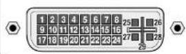
Pin No. Signal (Digital)
1 T.M.D.S Data 2 -
2 T.M.D.S Data 2 +
3 T.M.D.S Data 2 Shield
4 No connection
5 No connection
6 DDC Clock
7 DDC Data
8 No connection
9 T.M.D.S Data 1 -
10 T.M.D.S Data 1 +
11 T.M.D.S Data 1 Shield
12 No connection
13 No connection
14+5V Power
15 Ground
16 Hot Plug Detect
17 T.M.D.S Data 0
18 T.M.D.S Data 0 +
19 T.M.D.S Data 0 Shield
20 No connection
21 No connection
22 T.M.D.S Clock Shield
23 T.M.D.S Clack +
Signal Identification For Raster Preset
| Resolution (horizontal frequency/vertical frequency) | Factory settings | User settings | Sync polarity | Presence/absence of sync | RGB MODE | INPUT MODE*7 | |||
| Vertior | VerHor | ||||||||
| VIDEO NTSC*1 | YES | YES | - | - | - | - | |||
| VIDEO PAL*1 VIDEO SECAM*1 | YES | YES | - | - | - | - | |||
| 640 X 240 (15.734kHz/59.94Hz) | ISS-6010 NTSC*2 | YES | YES | NEG | NEG | YES | YES | - | 4 X 3 |
| 768 X 288 (15.557kHz/50.39Hz) | ISS-6010 PAL*2 | YES | YES | NEG | NEG | YES | YES | - | - |
| 640 X 480 (31.469kHz/59.94Hz) | VESA 480@60Hz | YES | YES | NEG | NEG | YES | YES | STILL | 4 X 3 |
| 640 X 480 (35kHz/66.667Hz) | MAC @13**5 | YES | YES | - | - | - | - | - | - |
| 640 X 480 (37.861kHz/72.809Hz) | VESA 480@72Hz*3 | YES | YES | NEG | NEG | YES | YES | - | - |
| 640 X 480 (37.5kHz/75Hz) | VESA 480@75Hz | YES | YES | NEG | NEG | YES | YES | - | - |
| 640 X 480 (43.269kHz/85.008Hz) | VESA 480@85Hz*3 | YES | YES | POS | POS | YES | YES | - | - |
| 640 X 480 (39.375kHz/75Hz) | XGA 2 480@75Hz*3 | YES | YES | NEG | NEG | YES | YES | - | 4 X 3 |
| 800 X 600 (35.156kHz/56.25Hz) | VESA 600@56Hz | YES | YES | POS | POS | YES | YES | - | 4 X 3 |
| 800 X 600 (37.879kHz/60.31Hz) | VESA 600@60Hz | YES | YES | POS | POS | YES | YES | - | 4 X 3 |
| 800 X 600 (48.077kHz/72.188Hz) | VESA 600@72Hz*3 | YES | YES | POS | POS | YES | YES | - | - |
| 800 X 600 (46.875kHz/75Hz) | VESA 600@75Hz*3 | YES | YES | POS | POS | YES | YES | - | - |
| 800 X 600 (53.674kHz/85.061Hz) | VESA 600@85Hz*3 | YES | YES | POS | POS | YES | YES | - | - |
| 832 X 624 (49.725kHz/74.55Hz) | MAC @15**3*5 | YES | YES | - | - | - | - | - | - |
| 852 X 480 (31.722kHz/59.966Hz) | I-O data wide*4 | YES | YES | NEG | NEG | YES | YES | - | 16 X 91 |
| 848 X 480 (31.02kHz/60Hz) | VGA WIDE (NEC01) | YES | YES | POS | POS | YES | YES | - | 16 X 9 |
| 1024 X 768 (56.476kHz/70.069Hz) | VESA 768@70Hz*3 | YES | YES | NEG | NEG | YES | YES | - | - |
| 1024 X 768 (60.023kHz/75.029Hz) | VESA 768@75Hz*3 | YES | YES | POS | POS | YES | YES | - | - |
| 1024 X 768 (68.677kHz/84.997Hz) | VESA 768@85Hz*3 | YES | YES | POS | POS | YES | YES | - | - |
| 1024 X 768 (60.24kHz/74.93Hz) | MAC @19**3*5 | YES | YES | - | - | - | - | - | - |
| 768 X 576 (31.389kHz/50Hz) | IDC-3000G PAL625P | YES | YES | NEG | NEG | YES | YES | - | - |
| 640 X 480 (31.47kHz/59.9Hz) | IDC-3000G NTSC 525P | YES | YES | NEG | NEG | YES | YES | MOTION | 4 X 3 |
Specifications
PlasmaSync 50PD2 (Model PX-50VP2G)
| Plasma Screen 50 inch Visual size | (Diagonal), AC Drive typeAspect ratio : 16:9Optical filler coatingDisplay color : 16,770,000 colors 256 levels |
| RGB Input Terminals RGB 1 : mini D SUB 15pinRGB 2 : BNC (R,G,B, H/CS, V) * Sync-on-Green compatible.RGB 3 : Digital RGB (DVI 24+5pin: Not compatible with analog input.Complies with DVIR/G/B Video : Analog 0.7Vp-p/75 Ohms (Positive)Sync. : Separate Sync. TTL level, 0.7 - 4.0Vp-p/75 Ohms......BNC onlyHorizontal Sync. (Positive/Negative)Vertical Sync. (Positive/Negative)Composite Sync. TTL Level (Positive/Negative)Composite Sync. On Green Video 0.3Vp-p (Negative) | |
| RGB Output Terminals BNC (R,G,B, H/CS, V)THROUGH OUT | |
| DVD/HD Input/Output Terminal BNC (Y,Cb/Pb,Cr/Pr)DVD/HD IN / THROUGH OUT Servos as RGB2 Input/output | |
| Video Input/Output Terminals 1.0Vp-p, 75 Ohms unbalanced (BNC-Jack). Composite video signal, Sync-negative.VIDEO IN / THROUGH OUT Y : 1.0Vp-p, 75 Ohms unbalanced, Sync-negative.S-VIDEO IN / THROUGH OUT C : 0.28Vp-p, 75 Ohms unbalanced, Color burst level. | |
| Audio Input/Output Terminals AUDIO IN : Stereo RCA X 2AUDIO OUT : Stereo RCA X 1 | |
| External Control mini D-SUB 9 pin (IN/THROUGH OUT)(IN/THROUGH OUT) RS-232C Control | |
| Synchronization Range Horizontal : | 15.5 to 68.7 KHz (automatic : step scan)Vertical : 46.0 to 85.0 Hz (automatic : step scan) |
Appendix
Troubleshooting
If the picture quality is poor or there is some other problem, check the adjustments, operations, etc., before requesting service.
| Symptom Checks | Remedy | |
| Mechanical sound Is heard | · Maybe the sound from the cooling fans used to prevent over heating. | |
| Picture is disturbed. Sound is noisy.Remote control unit operates erroneously. | · Is a connected component set directly in front or at the side of the display? | · Leave some space between the display and the connected components. |
| Monitor's power does not turn on when the remote control's power button is pressed. | · Is the monitor's power cord plugged into a power outlet? | · Plug the monitor's power cord into a power outlet. |
| · Are all the monitor's indicators off? | · Plug the monitor's power cord into a power outlet. | |
| · Has an ID number been set for the main unit? | · Set an ID number with the ID SELECT button, or set the ID number to ALL. | |
| · Are the remote control's batteries worn out? | · Replace both batteries with new ones. | |
| Monitor does not operate when the remote control's buttons are pressed. | · Is the remote control pointed at the monitor, or is there an obstacle between the remote control and the monitor? | · Point the remote control at the monitor's remote control sensor when pressing buttons, or remove the obstacle. |
| · Is direct sunlight or strong artificial light shining on the monitor's remote control sensor? | · Eliminate the light by closing curtains, pointing the light in a different direction, etc. | |
| · You are not within the effective operating range.(Wireless) | · Use the remote control unit within 30° left and right of center (at a distance of 22ft). | |
| · Has an ID number been set for the main unit? | · Set an ID number with the ID SELECT button, or set the ID number to ALL. | |
| · Are the remote control's batteries worn out? | · Replace both batteries with new ones. | |
| · The front panel buttons of the main unit do not function | · The front panel buttons do not function during Control Lock | |
| No Sound or Picture is produced. | · Is the monitor's power cord plugged into a power outlet? | · Plug the monitor's power cord into a power outlet. |
| · Power outlet inactive.Power of external equipment is not ON.External equipment has been incorrectly con- | · Be sure wall switch is on and outlet has power.Switch to ON or connect to an active AC outlet.Correct all connections. | |
Appendix
| Symptom Checks | Remedy | |
| Picture is unstable. | • Is the computer's resolution setting appropriate? | • Set to the proper resolution. |
| POWER/STANDBY Indicator Is lighted In orange or yellow. | • Horizontal and/or vertical sync signal is not present when the Intelligent Power Manager control is on. | • Check the input signal. |
| • POWER/STANDBY indicatoris flashing red or yellow. | • The unit is OFF in the timer operation; this is not a malfunction. See *1. | |
| POWER/STANDBY Indicator is blinking in green. | • The temperature inside the main unit has become too high and has activated the protector. | • Promptly switch off the power of the main unit and wait until the internal temperature drops. See *2. |
*1 In the following case, power off the monitor immediately and contact your dealer or authorized NEC Service Center.
The monitor turns off in 5 seconds after powering on and then the POWER/STANDBY indicator blinks. It indicates that the power supply circuit(flashing red), one or more fans (flashing yellow) have been damaged.
\*2 Overheat protector
If the monitor becomes too hot, the overheat protector will be activated and the monitor will be turned off. If this happens, turn off the power to the monitor and unplug the power cord. If the room where the monitor is installed is particularly hot, move monitor to a cooler location, and wait for the monitor to cool for 60 minutes. If the problem persists, contact your NEC dealer for service.
Appendix
Cabinet dimensions
PlasmaSync 50PD2 (Model PX-50VP2G)

natural_image
Technical line drawing of a mechanical component with symmetrical supports and a central vertical axis (no text or symbols)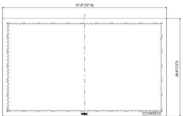
text_image
47.8"(1214) 26.6"(727) MFC 30080000