
Cyclo Directional IP65 - Unspecified MARTIN - Free user manual and instructions
Find the device manual for free Cyclo Directional IP65 MARTIN in PDF.

| Product Type | Fluorescent Tube Luminaire |
| Brand | Martin |
| Model | Cyclo Directional IP65 |
| Dimensions (L x W x H) | 1257 x 149 x 230 mm |
| Weight | 22 kg |
| Power Supply | 100-120 V or 200-240 V, 50/60 Hz |
| Lamp Type | T5 Fluorescent, Osram FQ 54 W HO |
| Number of Lamps | 3 (03 model) or 4 (04 model) |
| Color Mixing | RGB (03) or RGBW (04) |
| DMX Control | Yes, USITT DMX512/1990 |
| DMX Channels | 3 (03) or 4 (04) |
| Stand-alone Operation | Yes, programmable via DIP switch |
| Protection Rating | IP65 |
| Housing Material | Aluminum and stainless steel |
| Finish | Clear anodized |
| Front Cover | Toughened glass |
| Mounting | Surface mount, any orientation |
| Ambient Temperature Range | -20°C to 40°C |
| Cooling | Convection |
| Included Items | Tubes, mounting bracket, cable glands, blanking plugs, manual |
| Cleaning | Damp cloth with mild detergent; no high-pressure water jet |
| Safety | Grounding required; keep flammable materials away |
Frequently Asked Questions - Cyclo Directional IP65 MARTIN
User questions about Cyclo Directional IP65 MARTIN
0 question about this device. Answer the ones you know or ask your own.
Ask a new question about this device
Download the instructions for your Unspecified in PDF format for free! Find your manual Cyclo Directional IP65 - MARTIN and take your electronic device back in hand. On this page are published all the documents necessary for the use of your device. Cyclo Directional IP65 by MARTIN.
USER MANUAL Cyclo Directional IP65 MARTIN
Cyclo Directional IP65
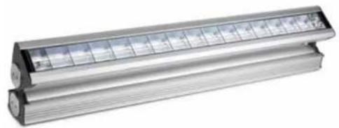
natural_image
Exterior view of a modern LED array light fixture (no text or symbols visible)user manual
Dimensions
Measurements are in millimeters

natural_image
Technical line drawing of a mechanical component with dimension标注 (no text or symbols)
Martin
©2007 Martin Professional A/S, Denmark. All rights reserved. No part of this manual may be
Safety information

WARNING!
Read the safety precautions in this section before installing, powering, operating or servicing this product.
The following symbols are used to identify important safety information:

Danger! Safety hazard. Risk of personal injury or death.

Danger! Hazardous voltage. Contact will cause electric shock.

Danger! Fire hazard.

Warning! Burn hazard. Hot surface. Do not touch.

DANGER! This product is not for household use. It presents risks of injury due to electric shock, fire, burns and falls if safety precautions are not followed.
Read this manual before installing, powering, operating or servicing the luminaire. Follow the safety precautions listed below, and observe all warnings in this manual and on the luminaire. Use the luminaire only as described in this manual and in accordance with local laws and regulations. Refer any operation not described in this manual to a qualified technician.
If you have any questions about how to operate this luminaire safely, contact your Martin Architectural supplier or call the Martin 24-hour service hotline on +45 70 200 201.

Protection from electric shock


• Always ground (earth) the luminaire electrically.
- Use only a source of AC power that complies with local building and electrical codes and has both overload and ground (earth) fault protection.
- Ensure that the AC power distribution system includes a means of isolating all installed devices from power and locking out power during service.
- Ensure that all components in the AC power distribution circuits (cables, junction boxes, etc.) are protected from water and airborne particles to IP67 or higher, are suitably dimensioned for the current and power requirements of the devices installed, and are of suitable type for the location (including water, pollution, temperature and UV resistance).
- Do not expose the luminaire to a high-pressure water jet.
- Do not immerse the luminaire in water or install it in a location where flooding may occur.
- Refer all service not described in this manual to a Martin service technician.
Protection from burns and fire
- Do not operate the luminaire if the ambient temperature (T a ) exceeds 40° C (104° F).
- Keep flammable materials well away from the luminaire.
- Allow the luminaire to cool for 15 minutes before servicing.
- Do not attempt to bypass thermostatic switches or fuses. Replace defective fuses with ones of the specified type and rating only.
- Do not modify the luminaire. Install only genuine Martin parts and approved fluorescent tubes of the type and wattage specified for the armature.
- Provide a minimum clearance of 25 mm (1 inch) and unobstructed airflow around the luminaire.
- Do not mask or modify light output with filters or other materials.
Protection from injury due to falls
- Block access below the work area and work from a stable platform whenever installing, servicing or removing the luminaire.
- Ensure that all supporting structures, surfaces, fasteners and lifting equipment can bear the weight of all the devices they are intended to support plus an adequate safety margin, and that they conform to local building and safety regulations.
- Use fasteners that have sufficient corrosion resistance, dimensions and
Contents
Safety information 3
Product overview....6
Introduction 7
Installation 8
Included items 8
Access to tube module 9
Access to connections compartment 10
Mounting 11
Orientation and adjustment.... 12
Cable entry 15
AC power 18
Linking luminaires for DMX and synchronized operation ..... 21
Operation: general 27
Fluorescent tube lifetimes and performance 27
Avoiding condensation and humidity. 27
Operation in extreme ambient temperatures.... 28
Stand-alone operation....29
Stand-alone operation settings 30
Single stand-alone operation 31
Master/client stand-alone operation 31
DMX-controlled operation.... 35
DMX control functions 35
Service 36
Cleaning 36
Tube replacement 36
Main fuse replacement 39
Voltage setting 40
Troubleshooting 41
DMX protocols 42
Cyclo IP65 Directional specifications 43
Product overview

A - Tube module
B - Base module
C - Front cover
D - Metal cable glands (if used)
Introduction
Thank you for selecting a luminaire from the Martin Architectural® Cyclo IP65 Directional series. Cyclo IP65 Directional luminaires are fluorescent tube-based dynamic color-changing luminaires designed for illumination of walls and surfaces. Dimmable 54 watt T5 fluorescent tubes combine high efficiency, bright color and long lamp life. Luminaires are designed for surface mounting, and adjustable arms allow tilting through a wide range of angles.
Cyclo IP65 Directional luminaires offer independent 0-100% control of tube intensity using a standard DMX controller. They can also be programmed to run stand-alone light shows alone or in synchronized groups.
Two models are available. The 03 has red, green and blue tubes, allowing RGB additive color mixing. The 04 has red, green and blue tubes plus a cool daylight white tube, allowing RGBW color mixing. The color temperature of the white tube's output can be controlled using the colored tubes.
Luminaires are dustproof and protected from water projections and low-pressure water jets to IP65. A self-purging humidity valve eliminates condensation. Luminaires can start and operate with tubes dimmed to 1% light output in ambient temperatures as low as -20irc C ( -4irc F).
Versions are available to suit the following voltage ranges:
- 120 V models accept 100-130 V nominal AC power at 50/60 Hz. - 230 V models accept 200-240 V nominal AC power at 50/60 Hz.
Martin Architectural can offer expert assistance with planning an installation, if desired.
Installation, on-site service and maintenance can be provided worldwide by the Martin® Global Service organization and its authorized agents. Choosing a Martin service contract gives owners access to Martin's expertise and product knowledge in a partnership that will ensure the highest level of performance throughout the product's lifetime.
The most recent version of this user manual is available from the Support area of http://www.martin-architectural.com
Installation

DANGER! Read "Safety information" on page 3 before attempting to install this product.
The safety and suitability of lifting equipment, installation location, anchoring method, mounting hardware and electrical circuits are the responsibility of the installer. All local safety regulations and legal requirements must be observed when installing and connecting the Cyclo IP65 Directional. Installation must be carried out by qualified professionals only.
This section describes how to install the luminaire, including how to connect it to power and control data cables, and how to set it up for DMX control or stand-alone operation.
We recommend that you read the Installation section of this manual and familiarize yourself with the procedures involved before starting to install luminaires. If you are not familiar with DMX, pay particular attention to the section on setting DMX addresses.
Included items
Cyclo IP65 Directional luminaires are supplied with the following items:
• Osram T5 fluorescent tubes (installed)
• Surface-mounting bracket.
- Two TET 5-7 Thorsman rubber membrane cable glands (installed) for data cable entry: cable diameter 5-7 mm (0.20-0.28 in.)
- Two TET 10-14 Thorsman rubber membrane cable glands (installed) for power cable entry: cable diameter 10-14 mm (0.40-0.55 in.)
- Two M25 metal blanking plugs (installed) for unused power cable entry holes.
- Two M16 metal blanking plugs (installed) for unused data cable entry holes.
- Two M25 metal IP68 cable glands (supplied loose) for AC power cable output, cable diameter 7.15 mm (0.28–0.9 in.)
Access to tube module
Various operations described in this manual require access to the inside of the module that contains the tubes. To access the inside of the tube module:
-
Isolate the luminaire from power and ensure that power cannot be reconnected.
-
See Figure 1. Loosen the three front cover release screws in the hinged front cover release flap until they turn freely.
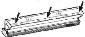
Figure 1: Front cover release screws
-
See Figure 2. Lift the release flap (A) and then lift the hinged front cover (B). If you need to lever the release flap up, use a plastic or wooden object, as a metal object may damage the glass. Avoid damaging seals while you are working.
-
To close the front cover, first close the cover (B), then close the release
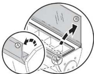
Figure 2: Opening the front cover
flap (A) so that it clips down over the cover. The seals on the inside faces of covers must be in perfect condition to maintain their waterproof qualities. Avoid damaging them. Any seal that is not in perfect condition
Access to connections compartment
Various operations described in the is manual require access to the connections compartment in the base module. To access the connections compartment:
- See Figure 3. Remove the two screws from the ends of the connections compartment cover.
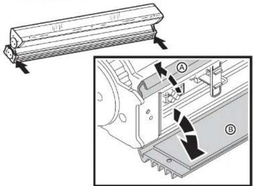
Figure 3: Opening the connections compartment cover
- Open the hinged release flap (A) and then open the hinged cover (B). Avoid damaging the seal on the inside of the cover.
- To close the connections compartment, first close the hinged cover (B), then close the release flap (A) so that it clips down over the cover. The seals on the inside faces of covers must be in perfect condition to maintain their waterproof qualities. Avoid damaging them. Any seal that is not in perfect condition must be replaced by a Martin service agent.
- Tighten the two screws at either end of the cover before applying power.
Mounting

DANGER! It is the installer's responsibility to ensure that the installation is safe and that all local safety regulations and legal requirements are observed when mounting the Cyclo IP65 Directional.
The Cyclo IP65 Directional can be surface-mounted on a floor, wall or ceiling. To surface-mount the Cyclo IP65 Directional:
- Ensure that the mounting surface is flat and can support the weight of all the devices to be installed on it. Allow 25 mm (1 inch) of free space around each luminaire.
- Using the mounting bracket as a guide, mark up and drill holes in the mounting surface to take mounting fasteners.
- Fasten the mounting bracket to the surface with at least two fasteners that have sufficient corrosion resistance and strength to mount the luminaire safely. Choice of mounting hardware will depend on the installation, but use high-quality corrosion-resistant fasteners with recommended minimum properties grade A4-70 (ISO 3506), or grade 8.8 (ISO 898-1). Any nuts used must be self-locking.
- Check that the bracket is not distorted and is securely attached to the mounting surface.
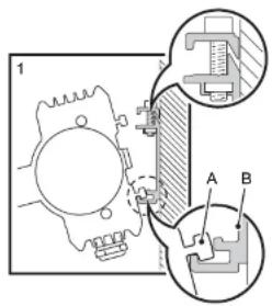

Figure 4: Installing on the mounting bracket
the T-section (C) on the upper side of the base passes behind the retaining rail (D).
- Tighten the retaining screws (E) so that the retaining rail (D) grips the T-section (C) tightly. Check that the luminaire is held securely.
Orientation and adjustment
Important! The Cyclo IP65 Directional support arms must both be fixed at the same angle. Do not twist the luminaire in the support arms, or you may deform the product and make it impossible to obtain a waterproof seal.
The Cyclo IP65 Directional can be installed in any orientation.


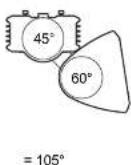
Figure 5: Tilt angle adjustment
See Figure 5. The angle of the support arms can be adjusted in the base module, and the tube module can be rotated in the support arms, allowing a
Adjusting the support arm angle
To adjust the angle of the support arms in the base module:
- Ensure that the luminaire is securely mounted and isolated from power.
- Open the connections compartment as described in "Access to connections compartment" on page 10.
- See Figure 6. Support the weight of the tube module. Loosen the arm adjustment screws at both ends of the base module with a long Allen key, tilt the arms to the desired angle and retighten slowly, rocking the tube module up and down slightly while you tighten so that the adjustment screws engage correctly in the cutouts in the arm.
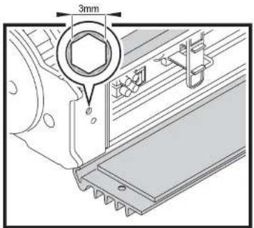
Figure 6: Arm-to-base adjustment screws
- Reinstall the connections compartment cover as described in "Access to connections compartment" on page 10.
Adjusting the tube module tilt angle
To rotate the tube module in the support arms:
- Ensure that the luminaire is securely mounted and isolated from power.
- Open the front cover as described in "Access to tube module" on page 9.
- See Figure 7. Loosen both the tilt adjustment screws with a long Allen key, rotate the tube module to the desired angle, and retighten.
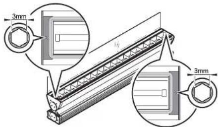
Figure 7: Tube module tilt adjustment screws
- Reinstall the front cover as described in "Access to tube module" on page 9.
Cable entry
Two types of seal can be used for cable entry:
Thorsman rubber
membrane cable glands (see Figure 9) installed in
the base module and
metal cable glands (see Figure 10) packed loose with the product. If the metal glands are used, blanking plugs must be removed and replaced with metal glands.
Use the larger glands for power cable entry and the smaller glands for DMX data cable entry.
natural_image
Technical line drawing of a mechanical assembly with multiple components and mounting holes (no text or symbols)Cable glands may need to
be replaced in the
following situations:
Figure 8: Cable gland options
- If power or data cable is used that is not within the diameters specified under "Included items" on page 8, new cable glands that match cable diameter must be obtained from Martin or an electrical supplier.
- Rubber and metal glands must be replaced with new items if cable in an existing installation is replaced with cable of a different diameter.
- Used rubber membrane glands must be replaced with new unpierced items or replaced with blanking plugs if they are no longer used for cable entry.
- If metal cable glands are installed, they must be replaced with blanking plugs if no longer used for cable entry.
Replacement rubber membrane glands must have the following characteristics:
Temperature range....-20° to +70°C or better Ingress protection rating....IP67 or IP68
Replacement metal glands must have the following characteristics:
Temperature range: -20° to +70°C or better
Ingress protection rating: IP67 or IP68
Power cable gland thread size: M25
Data cable gland thread size: M16
Minimum entry thread length: 10 mm (0.4 in.)
Installing cable using rubber membrane glands

DANGER! Using a rubber membrane gland involves making a hole in the membrane. A used gland is therefore only waterproof with cable installed. If the cable is removed, the hole in the housing must be sealed with a blanking plug or new gland.
To install cable using a rubber gland:

Figure 9: Thorsman rubber membrane cable glands
-
Push a round spiked object through the center of the membrane from the outside of the housing just enough to pierce it. Do not enlarge the hole or remove rubber from the membrane.
-
Push cable through the gland from the outside of the housing.
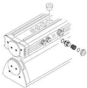
Installing cable using metal cable glands
Two sizes of metal cable gland are supplied loose with the product. Use the larger glands for power cable entry and the smaller glands for DMX data cable entry.
To install cable using a metal cable gland:
-
Remove a blanking plug that matches the cable gland size from the base module housing.
-
See Figure 10. Dismantle the cable gland.

- Ensure that there is a rubber O-ring A on the housing end of the cable entry B, and screw this end into the threaded hole in the housing. Tighten until the O-ring A makes a water-resistant seal against the outer surface of the housing. Do not over-tighten, as this may damage the seal or housing.
- Thread the cable through the compression nut E, washer D, gland C, and cable entry B into the housing.
- Allow approx. 20 cm (8 in.) of cable slack inside the housing. Prevent the cable entry from turning and tighten the compression nut sufficiently to make a water-resistant seal. Do not over-tighten, as this may damage the gland. Check that the cable is firmly gripped in the rubber gland.
AC power

DANGER! It is the installer's responsibility to ensure that all power cable and equipment is adequately dimensioned and of appropriate type for the installation, and that all local safety regulations and legal requirements are observed when installing and connecting the Cyclo IP65 Directional.
Current and power data are given in the Specifications section on page 43.

Inrush currents and electronic circuit-breakers
When fluorescent tubes with ECG (electronic control gear) systems are switched on at the AC wave peak, a larger current surge occurs than with conventional ballasts. If a large number of luminaires are switched on simultaneously, this inrush current can trip electronic circuit breakers. To avoid this in large installations, either switch on luminaires at intervals or limit the number of luminaires per 16 A electronic circuit breaker to approximately ten luminaires.
RCDs and common neutral conductors
Many fixed installations use common neutral conductors in branch circuit distribution boxes. To avoid unintentional tripping of the RCD (residual current device, or ground fault/earth leakage circuit breaker), ensure that each luminaire's neutral conductor is connected to AC power via the same RCD as the live conductor.
Leakage to ground and RCDs
Each ECG "leaks" a total current of maximum 0.5 mA to ground (earth). Luminaires must be correctly connected to ground so that this "leakage" current can be absorbed.
Allow for the "leakage" current from ECGs when connecting luminaires to a circuit that has an RCD for ground fault protection, otherwise the RCD may trip unintentionally. Bear in mind that RCDs are rated at their maximum trip current, and that some RCDs rated 30 mA may trip when leakage to ground is as low as 20 mA.
RCDs can also be tripped by the inrush current when tubes are switched on.
To avoid unintentional tripping of RCDs:
- Distribute power using 3-phase and install 3-phase PCDs
permitted RCD trip current ratings are normally stated in national electrical and building codes.
- Install surge current-resistant RCDs.
Connecting to power
A screw clamp is provided for connecting the luminaire to the power cable's earth conductor, and a block of spring-loaded clamp terminals are provided for connecting the luminaire to the power cable's live and neutral power conductors. Some common color-coding systems for power wiring are given below:
Wire (EU) Wire (US) Pin Marking on luminaire
| brown black live L1 | ||
| blue white neutral N | ||
| yellow/green green ground |
Table 1: Power cable color-coding systems
To connect to AC power:
- Ensure that power cannot be applied to the cable during installation.
- Open the connections compartment as described in "Access to connections compartment" on page 10.
- Pass the power input cable through a cable gland as described in "Cable entry" on page 15 so that approximately 20 cm (8 in.) of cable is free inside the luminaire, and prepare the end of the cable for connection.
-
See Figure 11. Four spring-loaded terminals marked L1, L2, L3 and N and one screw clamp marked are provided for power cable connection. The terminals marked L2 and L3 are not used to supply power to the luminaire and are provided only to allow phase conductors to be connected if power is supplied from a 3-phase system (see "Connecting to a 3-phase system" on page 20).
-
Connect the
conductors in the power input cable as follows:
- Connect the ground (earth) wire to the screw terminal marked ⏻ close to the power terminals.
- Connect the neutral wire to the spring-loaded power terminal marked N
-
Connect the live wire to the spring loaded power terminal marked L1.
-
If power is to continue to another luminaire, pass power output cable through a cable gland as described in "Cable entry" on page 15 and prepare the end of the cable for connection. Each spring-loaded terminal has two holes. One hole now contains a conductor from the input cable and one is available for a conductor from the output cable. Using the spare holes, connect the conductors in the power output cable as described under point 5. above.
DMX terminalsPower ter

Figure 11: Power and DMX connections
Connecting to a 3-phase system
If you are supplying luminaires with power from a 3-phase system, the live conductor in the power input cable that you connect to terminal L1 will be one of the phases. Connect one of the remaining phases to terminal L2 and the last remaining phase to terminal L3.
To distribute the load evenly over the 3 phases, connect phase 1 to terminal L1 on one-third of the luminaires in the installation, phase 2 to terminal L1 on one-third of the luminaires, and phase 3 to terminal L1 on the remaining one-third of the luminaires. Terminals L2 and L3 do not supply power to the luminaire and are provided simply to allow phase conductors in separate lengths of power cable to be joined.
To avoid confusion, each time you install a power output cable to take power
After making power connections
If you are installing DMX data cables, continue to the next section. Otherwise, close the connections compartment as described in "Access to connections compartment" on page 10.
Linking luminaires for DMX and synchronized operation
You need to create a data link to:
• Control luminaires with a DMX control device.
- Operate two or more Cyclo IP65 Directionals in master/client stand-alone mode, where all luminaires run a synchronized light show without a separate DMX control device.
A reliable data connection requires suitable cable. CAT 5 (category 5) UTP (unshielded twisted pair) network cable is suitable for this purpose. The minimum recommended wire size is 0.2 mm2 (24 AWG) for runs up to 300 meters (1000 ft.) and 0.322 mm2 (22 AWG) for runs up 500 meters (1640 ft.). Your Martin Architectural supplier can advise and supply suitable cable.
Luminaires on a serial data link must be daisy-chained in one single line, maximum 500 meters (1640 ft.) long, with maximum 32 luminaires. To exceed 32 luminaires or 500 meters, or to add branches, an optically isolated amplifier-splitter such as the Martin RS-485 Opto-Splitter (P/N 90758060) must be used.
A male 3-pin XLR connector can be fitted at the controller end of the data link to allow a standard connection to Martin DMX controller. The XLR connector should be wired as follows:
- Pin 1: shield
• Pin 2: DMX - (cold)
• Pin 3: DMX + (hot)
To avoid ground (earth) loop interference, make sure that the DMX cable shield does not come into contact with the shell or body of the XLR connector.
A screw-type terminal block is provided in the connections compartment for connecting the data link. The data input and data output cables must both be connected to this terminal block. The data output may only be used to
Connecting to control data
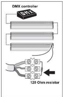

To create the data link:
- If using a DMX control device, run suitable cable from the controller's DMX output to the first luminaire on the link.
- Use an M16 cable gland to run the data cable through the housing (see "Cable entry" on page 15).
- Connect the data cable wires to the data terminal block (see "DMX terminals" in Figure 11). Wiring polarity is labelled on the luminaire.
- Continue connecting up to 32 luminaires using the above procedure.
- Terminate the data link by connecting a 120 Ohm, 0.25 W resistor across the + (hot) and - (cold) terminals of the last luminaire's terminal block.
Tip! Random "flicker" and other unexplained control problems during stand-alone master/FILHQN operation can often be cured by also connecting a 120 Ohm resistor across the + (hot) and - (cold) terminals of the first luminaire's data connection terminal block.
Configuring luminaires for DMX or stand-alone operation
Each DMX model Cyclo IP65 Directional luminaire needs to be set up for DMX or stand-alone operation using the DIP switch located on the circuit board in the base module.

Figure 12: DIP switch
Configuring for DMX operation
DMX operation is enabled by setting pin 10 on the DIP switch to OFF. Pins 1 - 9 are then used to set the luminaire's control address.
The Cyclo IP65 Directional uses one DMX channel to control each tube. The DMX address, also known as the start channel, is the first of these channels. It must be set on the luminaire (and selected on the DMX controller) before the controller can send commands to the luminaire via a data link. For example, a Cyclo 04 IP65 Directional with its DMX address set to 101 uses channels 101, 102, 103 and 104 to control its four tubes.
Allow enough channels when setting the DMX address. If control channels for two luminaires overlap, one of the luminaires will receive the wrong commands.
If two or more Cyclo IP65 Directional luminaires share the same DMX address, they will receive the same commands and respond identically. Individual control will be impossible.
- Decide on a DMX address for the luminaire. If you are calculating the DMX addresses for multiple luminaires, save time by using the online Martin Address Calculator at http://www.martin.dk/service/utilities/AddrCalc/index.asp (see illustration below).
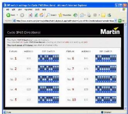
- You can also look up DIP switch settings using the Martin DIP Switch Calculator, available for use and downloadable at http://www.martin.dk/service/dipswitchpopup.htm If you do not have Internet access, refer to "Table 2: DMX address DIP switch settings" on page 25.
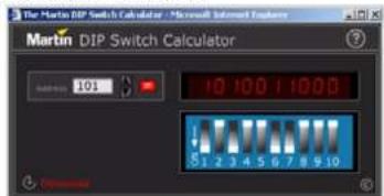
To use this table, first find the DMX address in the main block in the table. Then read the settings for pins 1 - 5 to the left and read the settings for pins 6 - 9 above the address. "0" means OFF and "1" means ON.
For example, to set the DMX address to 101, you need to set DIP switch pins 1, 3, 6 and 7 to ON, as highlighted in the table.
| DIP switch pins setting0 = OFF1 = ON | #30000300011111 | ||||||||||||||||||||
| #80001110400111 | |||||||||||||||||||||
| #100190110410011 | |||||||||||||||||||||
| #5001001002021 | |||||||||||||||||||||
| 414243445 | |||||||||||||||||||||
| 30:5003264961281621907204256288026375364436496401 | |||||||||||||||||||||
| 10:00135639712516119225257289321853385414649481 | |||||||||||||||||||||
| 0 | 1 | 0 | 0 | C | 2 | 30 | 68 | 98 | 130 | 162 | 199 | 228 | 258 | 290 | 322 | 354 | 386 | 418 | 450 | 482 | |
| 11:0033567691311631922725629013205337614951083 | |||||||||||||||||||||
| 30:003436612013126416228262923205536840457484 | |||||||||||||||||||||
| 1 | 0 | 1 | 0 | 0 | 3 | 37 | 69 | 100 | 132 | 165 | 197 | 229 | 261 | 293 | 325 | 357 | 389 | 421 | 453 | 485 | |
| 31:0035370102213418618823042622943233583042655485 | |||||||||||||||||||||
| 11:007377103131567192312623957035695143655487 | |||||||||||||||||||||
| 0 | 0 | 0 | 1 | C | 8 | 40 | 72 | 104 | 136 | 163 | 200 | 232 | 264 | 296 | 328 | 360 | 392 | 424 | 456 | 488 | |
| 10:109273105137189201233265297320361304265789 | |||||||||||||||||||||
| 01:31042747851301702022142602983076319426458430 | |||||||||||||||||||||
| 1 | 1 | 0 | 1 | C | 11 | 43 | 75 | 107 | 139 | 171 | 203 | 235 | 267 | 299 | 331 | 363 | 395 | 427 | 459 | 491 | |
| 30:10124476108140172042362680098236396284606392 | |||||||||||||||||||||
| 10:101345771091417352053726950130336539729461639 | |||||||||||||||||||||
| 0 | 1 | 1 | 1 | C | 14 | 46 | 78 | 110 | 142 | 174 | 206 | 238 | 270 | 303 | 334 | 366 | 398 | 430 | 462 | 494 | |
| 1 | 1 | 1 | 1 | C | 15 | 47 | 79 | 111 | 143 | 175 | 207 | 239 | 271 | 302 | 335 | 367 | 399 | 431 | 463 | 495 | |
| 0 | 0 | 0 | 0 | 1 | 16 | 48 | 80 | 112 | 144 | 176 | 208 | 240 | 272 | 304 | 336 | 368 | 400 | 432 | 464 | 496 | |
| 1 | 0 | 0 | 0 | 1 | 17 | 49 | 81 | 113 | 145 | 177 | 209 | 241 | 273 | 305 | 337 | 369 | 401 | 433 | 465 | 497 | |
| 0 | 1 | 0 | 0 | 1 | 18 | 30 | 82 | 114 | 146 | 178 | 210 | 242 | 274 | 306 | 338 | 370 | 402 | 434 | 466 | 498 | |
| 1 | 1 | 0 | 0 | 1 | 19 | 51 | 83 | 115 | 147 | 179 | 211 | 243 | 275 | 307 | 339 | 371 | 403 | 435 | 467 | 499 | |
| 0 | 0 | 1 | 0 | 1 | 20 | 52 | 84 | 116 | 148 | 180 | 212 | 244 | 276 | 308 | 350 | 372 | 404 | 436 | 468 | 500 | |
| 1 | 0 | 1 | 0 | 1 | 21 | 53 | 85 | 117 | 149 | 181 | 213 | 245 | 277 | 309 | 341 | 373 | 405 | 437 | 469 | 501 | |
| 0 | 1 | 1 | 0 | 1 | 22 | 54 | 86 | 118 | 150 | 182 | 214 | 246 | 278 | 310 | 362 | 374 | 406 | 438 | 470 | 502 | |
| 1 | 1 | 1 | 0 | 1 | 23 | 55 | 87 | 119 | 151 | 183 | 215 | 247 | 279 | 311 | 343 | 375 | 407 | 439 | 471 | 503 | |
| 30:1124565820152184216242680123437940640472504 | |||||||||||||||||||||
| 10:15125769212.131832172492815133653740944175005 | |||||||||||||||||||||
| 0 | 1 | 0 | 1 | 1 | 26 | 58 | 90 | 122 | 154 | 185 | 218 | 250 | 282 | 314 | 346 | 375 | 410 | 442 | 476 | 506 | |
| 1 | 1 | 0 | 1 | 1 | 27 | 59 | 91 | 123 | 155 | 187 | 219 | 251 | 283 | 315 | 347 | 375 | 411 | 463 | 475 | 507 | |
| 00:1128509224156188202522543163493841244476508 | |||||||||||||||||||||
| 1 | 0 | 1 | 1 | 1 | 29 | 61 | 93 | 125 | 157 | 189 | 221 | 253 | 285 | 317 | 349 | 382 | 413 | 445 | 477 | 509 | |
| 0:1113052942651501802225428651836538241496478510 | |||||||||||||||||||||
| 1:111316395271591812325528751936108341547478511 | |||||||||||||||||||||
Configuring for stand-alone operation
Stand-alone operation is enabled by setting pin 10 on the DIP switch to ON and pin 8 to OFF. The other pins are then used to program the luminaire. See "Stand-alone operation settings" on page 30 for details of how to set these pins.
After making connections
After you have finished making power and data connections, make sure that any holes not used for cable entry are sealed either with blanking plugs or unpierced membrane cable glands, then close the connections compartment as described in "Access to connections compartment" on page 10 before applying power.
Operation: general

DANGER! Read "Safety information" on page 3 before operating this product!
Fluorescent tube lifetimes and performance
The Osram high output T5 tubes fitted as standard meet color specifications for at least 10 000 hours. Average tube life is 20 000 hours, but note that tube life will vary depending on operating conditions.
Each power off/on cycle reduces tube life by approximately 30 minutes. To optimize tube life when controlling via DMX, do not dim tubes below DMX value 3 (i.e. approximately 1%) when they are not required in the color mix. To optimize tube life in stand-alone mode, program color-changing cycles that run as slowly as possible. For more detailed information on maximizing tube lifetimes, see the Martin website at http://www.martin.com/service.
Achieve optimum tube performance by 'burning in' new fluorescent tubes, i.e. running them for 100 hours at full power.
Avoiding condensation and humidity
Excess humidity inside the luminaire can be experienced if:
• Seals are affected because covers are distorted or not correctly fastened
- Cable glands are not correctly assembled and tightened
• Cable diameters are not correct for cable glands
- Blanking plugs are not correctly fitted and tightened
- Cables open into damp or wet locations (e.g. poorly sealed junction boxes), which will encourage moisture to pass along the cable into the luminaire.
The Cycle IDSE Directional is fitted with a self nursing value that gradually
or two with the front cover removed so that air circulates, then refit the front cover while the luminaire is hot. If you do this:
- The exposed internal components present a risk:, so block public access.
- Ensure that no dust or objects enter the luminaire while it is open.
Operation in extreme ambient temperatures
Do not operate the Cyclo IP65 Directional if the ambient temperature exceeds 40°C.
Cyclo IP65 Directional luminaires can be operated in ambient temperatures as low as -20ircC (-4ircF) , but a combination of low temperature and low dimming level will give a risk of flickering and cause voltage across tubes to rise. In extreme cases, luminaires will shut down power to tubes to avoid damage to components. If this happens, luminaires must be reset by powering them off and on again before tubes can be restarted.
Flickering can be avoided at ambient temperatures below freezing point if luminaires are operated so that they generate their own heat and maintain tube temperature at or above freezing point. For best low-temperature dimming performance:
- As soon as the ambient temperature falls below 0ircC (32°F), apply power permanently to luminaires. If light output is not required, reduce output by dimming tubes instead of shutting down power completely.
- If flickering occurs when dimming, increase the minimum dimming level.
- If flickering occurs when dimming luminaires after startup, start luminaires at full power for several minutes.
As a general rule, the higher the light output, the lower the ambient temperature luminaires can tolerate.
Stand-alone operation

DANGER! Read "Safety information" on page 3 before attempting to operate this product!
In stand-alone operation, the Cyclo IP65 Directional can run light shows without a DMX controller. Luminaires can be programmed to change colors in cycles. Changes can be programmed at 1, 5, 10 or 30 second intervals.
Two stand-alone operation modes are available:
- In single stand-alone operation, luminaires run independently of each other. No data link is required.
- In master/F(HQ) stand-alone operation, luminaires must be linked with a serial data link ("Linking luminaires for DMX and synchronized operation" on page 21 explains how to install this link). Synchronized action in all luminaires is triggered by one "master" luminaire.
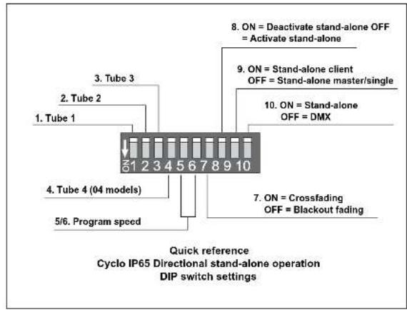
In both single and master/client stand-alone operation, luminaires are programmed by setting the pins on the DIP switch on the circuit board as shown in the following table.
Pin Function
| 1 White | active (04 models), red active (03 models) | ||
| 2 Red | active (04 models), green active (03 models) | ||
| 3 Green | active (04 models), blue active (03 models) | ||
| 4 Blue | active (04 models) | ||
| 5 & 6 Program speed | |||
| Pin 6 Pin 5 Speed | |||
| OFF OFF 1 sec. steps (fastest setting) | |||
| OFF ON 5 sec. steps | |||
| ON OFF 10 sec. steps | |||
| ON ON 30 sec. steps (slowest setting) | |||
| 7 OFF = Blackout fading, ON = Crossfading | |||
| 8 | OFF = Run program, ON = Deactivate program (Note: always set to OFF) | ||
A quick reference table covering DIP switch functions is also provided on the back cover of this manual.
Stand-alone operation settings
Activating tubes
DIP switch pins 1 to 3 (03 models) or 1 to 4 (04 models) activate tubes in the stand-alone program.
Setting program speed
Combinations of DIP switch pins 5 and 6 allow one of four different speeds to be set.
Note that the speed of color changes affects tube life (see "Fluorescent tube lifetimes and performance" on page 27).
Fading between colors
If DIP switch pin 7 is set to OFF (blackout fading), colors fade to almost blackout before the next color fades in.
If DIP switch pin 7 is set to ON (crossfading), color fading overlaps. If two or more colors are active, one color fades in while another is fading out, giving a color mixing effect. For example, if red and blue are activated and crossfading is selected, colors will crossfade from red through purple to blue, then back through purple to red in a continuous cycle (see example).

line
| Time | Red Line (%) | Blue Line (%) | |------|--------------|---------------| | 0 | 100 | 0 | | 50 | 50 | 100 | | 100 | 100 | 0 | | 150 | 50 | -100 | | 200 | 100 | 0 |Single stand-alone operation
In single stand-alone operation, a luminaire runs its own program independently of all other luminaires. To do this, the luminaire must be set as a master.
Activating single stand-alone operation
To activate single stand-alone operation:
-
Set DIP switch pin 10 to ON (switches from DMX to stand-alone mode).
-
Set DIP switch pin 9 to OFF (activates master mode).
-
Set DIP switch pin 8 to OFF (activates stand-alone mode)
-
Program the luminaire using DIP switch pins 1 - 7 (see table on page 29).
Master/ Client stand-alone operation
Important! Do not set more than one luminaire on a data link as master, and do not set a luminaire as master on a data link with a DMX controller. Doing so may cause damage to the electronics that is not covered by the product warranty.
In master/client stand-alone operation, one master luminaire transmits a synchronizing signal to client luminaires over the data link each time it starts a new action. Client luminaires start their next programmed action when they receive this signal from the master luminaire. Programs can be identical on all luminaires, or luminaires can – subject to certain practical constraints – run programs that are synchronized but not identical.
Note that each luminaire follows the program set on its own DIP switch as described in the table on page 29.
Note also that colors are always displayed in the order: white → red → green → blue.
This means for example that if white is activated, it will always be first in the program. If white is not activated but red is activated, red will be first in the program.
More sophisticated light shows can be programmed using a DMX controller (see "DMX-controlled operation" on page 35).
operation. Consult your Martin Architectural supplier if you need advice on combining and controlling products.
Identical light shows
Master and client luminaires can be set to behave identically. In this mode, the master sends synchronizing signals to the clients, and all luminaires run the same light show. Each client luminaire follows the program set on its own DIP switch, so for identical operation, all luminaires' DIP switch settings must be the same apart from pin 9, which is set to ON for clients and OFF for the master.
Synchronized non-identical light shows
It is also possible to synchronize changes but program client luminaires to behave differently from the master. To use this feature effectively, you need to plan your light show using scenes as building blocks and set the luminaires' DIP switches accordingly.
A scene is a change from one output to another. When a luminaire is in client mode, it starts a scene when it receives a synchronization signal from the master. The time taken by the scene is determined by the speed setting of the DIP switch. A client will not respond to new synchronization signals until its scene is complete.
When crossfading is selected, each color takes up one scene (fade in only). When blackout fading is selected, each color takes up two scenes (fade in and fade out). This means that the maximum number of scenes that can be programmed is twice the number of tubes installed, with all tubes activated and blackout fading selected.
Each time the master luminaire starts at scene 1, it sends a signal to all the client luminaires to start at scene 1. This means that if a client luminaire has:
-
Fewer scenes than the master luminaire, it will run these in a cycle until the master luminaire signals that the program should start from the beginning again.
-
More scenes than the master, the additional scenes will never run, because the program will reset to the first scene when the master starts its program from the beginning.
Here is an example of what will happen when a client luminaire has fewer scenes than the master luminaire:
Luminaire setting Scene pattern
Program examples
The following examples of programs show how an individual luminaire's
program is made up of scenes.
The following symbols are used in program diagrams:

Tube turned fully off
Fade in
Fade out
Fade to 50% and back to 100% in one scene (applies when only one color is active and crossfading is selected)
Example 1
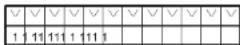
DIP switch 7 is set to ON (crossfading) and only red is activated:
Red
Scene
Example 2
DIP switch 7 is set to OFF (blackout fading) and only red is activated:
Red
Scene

Example 3
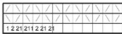
DIP switch 7 is set to ON (crossfading) and red and blue are activated:
Red
Blue
Scene
Example 4
DIP switch 7 is set to OFF (blackout fading) and red and blue are activated:
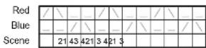
Example 5
To achieve a rainbow effect, activate red, green and blue tubes and set DIP switch pin 7 to ON (crossfading).

Activating master/client stand-alone operation
To activate master/client stand-alone operation:
- Isolate all luminaires from power.
- Set all luminaires as clients and enable stand-alone mode by setting DIP switch pins 9 and 10 to ON and pin 8 to OFF.
- Decide which luminaire to use as master and set this luminaire's DIP switch pin 9 to OFF. Note that any luminaire can be set as master, but you will obtain the most reliable data signal by either setting the first luminaire on the link as master or using 120 Ohm resistors to terminate the data link (see "Connecting to control data" on page 22) at both ends.
- When power is applied, client luminaires will go to the next scene in their program each time the master goes to its next scene. Client luminaires will also start scene 1 of their programs each time the master starts scene 1 of its program.
DMX-controlled operation

DANGER! Read "Safety information" on page 3 before attempting to operate this product!
Cyclo IP65 Directional DMX models may be operated with any lighting control device that is compatible with the USITT DMX (1990) standard.
For details of connecting luminaires on a data link to a DMX controller, see "Linking luminaires for DMX and synchronized operation" on page 21.
For details of setting up luminaires for DMX control, see "Configuring luminaires for DMX or stand-alone operation" on page 23
DMX control functions
The Cyclo IP65 Directional's advanced fluorescent tubes can be dimmed from maximum output right down to zero using one channel per tube on a DMX controller. This allows a wide range of color shades with variable intensity to be obtained using additive color mixing. On 04 models the color temperature of white light can also be fine-tuned.
Depending on the functions available on the controller, sophisticated light shows on the Cyclo IP65 Directional can be programmed over time, allowing constantly and rapidly shifting color mixes, or color displays which change slowly according to the time of day, or even year, for example. See the controller's manual for details.
Your Martin Architectural supplier can advise about available controllers and control options.
Service

DANGER! Read "Safety information" on page 3 before attempting to service this product!
With long-life fluorescent tubes and no moving parts, the Cyclo IP65 Directional is almost service-free, but this section describes the minimum of periodic maintenance required.
Refer any service operation not described in this manual to an authorized Martin service agent.
Cleaning
Use a damp cloth or soft brush soaked in a solution of water and a mild detergent cleaner such as auto shampoo to clean luminaires. Do not use abrasive, acidic or caustic cleaning products, or you will damage the luminaires' anodized finish.
Do not use a high pressure water-jet for cleaning: IP65 luminaires are protected against water projections and low-pressure water jets only.
Tube replacement
To replace the tubes in the Cyclo IP65 Directional:
- Isolate the luminaire from power and ensure that power cannot be reapplied, even accidentally.
-
Loosen the front cover release screws, lift up the release flap and open the front cover as described in "Orientation and adjustment" on page 12.
-
See Figure
-
Remove the reflector by lifting it out of the tube module housing.
-
In 04 models, remove the white tube by holding the metal caps at both ends of the tube, rotating the tube approx.
either direction, and sliding the tube's terminal pins out of their sockets. Support the tube at both ends as it is released.
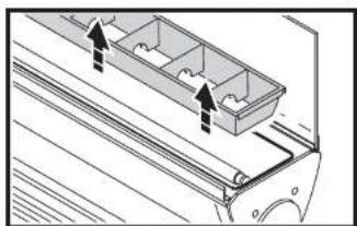
- See Figure 14. To release the diffuser, push the locking bars from position B in towards the center of the luminaire until they are in position A. Lift the diffuser out of the luminaire.
natural_image
Technical line drawing of a mechanical component with two arrows indicating direction (no text or symbols)Figure 13: Removing the reflector
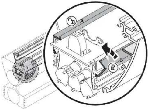
- When installing new tubes, line them up so that the manufacturer's markings on all tubes are at the same end of the luminaire. Tube positions are labelled R for red, G for green and B for blue. Slide each tube's terminal pins fully into their sockets and rotate the tube approx. 1/4 turn in either direction to engage the pins. Check that tubes are held securely.
- Reinstall the diffuser, reflector, white tube (in 04 models) and front cover before reapplying power.
Tube positions
The burning positions of fluorescent tubes affect their warm-up times, operating temperature, light output and tube life. For optimum results:
- Install tubes so that the manufacturer's markings are all at the same end of the luminaire.
- If the luminaire is installed in a vertical position or at an angle from the horizontal, locate the ends of the tubes that carry the manufacturer's markings at the lower end of the luminaire. However, in a cold environment, i.e. where temperatures are generally around or below freezing point, locate the markings at the upper end of the luminaire).
Main fuse replacement
The main fuse is located on the PCB in the ballast tray. See page 43 in the Specifications section for details of fuse types and ratings. Never replace a fuse with one of a different type or rating.
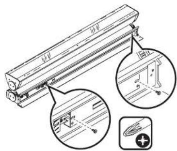
Figure 15: Removing the PCB
To replace the fuse:
- Isolate the luminaire from power and ensure that power cannot be reapplied accidentally.
- Open the connections compartment cover as described in "Access to connections compartment" on page 10.
-
See Figure 15. Undo the two retaining screws from the ballast tray and slide the tray out of the housing.
-
See Figure 16. Replace the main fuse on the PCB with one of the same type and rating.
![Main fuse [230V 115V]](/content/2026/06/1215679/images/a787062077b3b367e294cf25c88b309c600eb4e258f1e1f76e4a4dbae268918e.jpg)
Figure 16: Main fuse
- Reinstall all covers before reapplying power.
If a fuse blows repeatedly, refer to your Martin Architectural supplier for service.
Voltage setting
See Figure 16. The voltage switch on the PCB is factory-set to match 100-120 or 200-240 V nominal AC power at 50 or 60 Hz.
Important! Do not change the voltage setting without first consulting your Martin Architectural supplier.
Troubleshooting
Problem Probable cause(s) Remedy
| No response from luminaire when power is applied. | No power to luminaire. Check power connections. | |
| Ground fault protection circuit breaker (RCD) has tripped. | Reset RCD. If problem persists, have an electrician replace the RCD or reduce the number of luminaires powered via one RCD. | |
| If running in stand-alone mode, DIP switch pin 8 is set to ON. | Set DIP switch pin 8 to OFF to allow stand-alone operation. | |
| Luminaires do not respond correctly to DMX control. | Controller not connected. Check DMX data link. Inspect connections and test cables. Repair or replace as necessary. | |
| Incorrect DMX addressing. Check address setting on luminaire and controller. | ||
| Data link not terminated. Connect 120 Ohm termination resistor across data link + (hot) and - (colc) in parallel with last luminaire on link. | ||
| Two devices transmitting on link. | Check that all luminaires are set as clients (DIP switch pin 9 ON). | |
| Defective luminaire. Bypass luminaires one at a time until normal operation is regained to identify faulty luminaire. Have faulty luminaire tested and repaired by Martin service technician. | ||
| Luminaires do not behave correctly in master/client mode | Two luminaires transmitting on link. | Check that only one luminaire is set to operate as master. |
| Defective luminaire. Bypass luminaires one at a time until normal operation is regained to identify faulty luminaire. Have faulty luminaire tested and repaired by Martin service technician. | ||
| Poor quality light output and/or color rendering | Tube or tubes not burnt in. Run tubes at 100% intensity for 100 hours to burn in. | |
DMX protocols
Cyclo 04 IP65 Directional
| Channel Value Percent Function | |||
| 1 | 0-23-252253-255 | 01 - 99100 | White intensityTube offIntensity 1 → 100% Intensity 100% |
| 2 | 0-23-252253-255 | 01 - 99100 | Red intensityTube offIntensity 1 → 100% Intensity 100% |
| 3 | 0-23-252253-255 | 01 - 99100 | Green IntensityTube offIntensity 1 → 100% Intensity 100% |
| 4 | 0-23-252253-255 | 01 - 99100 | Blue IntensityTube offIntensity 1 → 100% Intensity 100% |
Table 5: DMX protocol, Cyclo 04 IP65 Directional
Cyclo 03 IP65 Directional
| Channel Value Percent Function | |||
| 1 | 0-2 | 0 | Red intensityTube offIntensity 1→100%Intensity 100% |
| 3-252 | 1 - 99 | ||
| 253-255 | 100 | ||
| 2 | 0-2 | 0 | Green intensityTube offIntensity 1→100%Intensity 100% |
| 3-252 | 1 - 99 | ||
| 253-255 | 100 | ||
| 3 | 0-2 | 0 | Blue IntensityTube offIntensity 1 → 100% |
| 3-252 | 1 - 99 | ||
Cyclo IP65 Directional specifications
Physical
L x W x H 1257 x 149 x 230 mm (49.5 x 5.9 x 9.1 in.)
Weight 22 kg (48.5 lbs)
Lamp
Type T5 fluorescent tubes
Approved lamps Osram FQ 54 W HO
Average tube life 20 000 hours
Socket G5
Dynamic effects
Color mixing....RGB (03 models) RGBW (04 models)
Red. 0 - 100%
Green 0 - 100%
Blue 0 - 100%
Cool white (4000 K) 0 - 100% (04 models)
Control and programming
Control options ..... DMX, stand-alone, synchronized (master/client)
Number of DMX channels .....3 (03 models), 4 (04 models)
DMX address setting ....DIP switch
Stand-alone and master/client programming .... DIP switch
Protocol USITT DMX512/1990
Receiver RS-485
Construction
Housing …… Aluminum and stainless steel
Finish .... Clear anodized
Front cover ....Toughened glass
Reflectors....High specular 99.9% aluminum
Protection factor IP65
Installation
Orientation Any
Minimum free space around luminaire .....25 mm (1 inch)
Electrical
| AC power | 100-120/200-240 V nominal, 50/60 Hz |
| Main fuse, 03, 120 V model | 2 AT (slow blow) |
| Main fuse, 04, 120 V model | 2.5 AT (slow blow) |
| Main fuse, 03, 230 V model | 1 AT (slow blow) |
| Main fuse, 04, 230 V model | 2 AT (slow blow) |
Typical power and current
Cyclo IP65 03 Directional, 120 V model
| 100 V, 60 Hz. | 163 W, 1.6 A |
| 120 V, 60 Hz. | 180 W, 1.5 A |
Cyclo IP65 03 Directional, 230 V model
| 208 V, 60 Hz. | 180 W, 0.9 A |
| 230 V, 50 Hz. | 181 W, 0.8 A |
| 240 V, 50 Hz. | 179 W, 0.8 A |
Cyclo IP65 04 Directional, 120 V model
| 100 V, 60 Hz. | 219 W, 2.2 A |
| 120 V, 60 Hz. | 236 W, 2.0 A |
Cyclo IP65 04 Directional, 230 V model
| 208 V, 60 Hz. | 235 W, 1.2 A |
| 230 V, 50 Hz. | 234 W, 1.1 A |
| 240 V, 50 Hz. | 231 W, 1.0 A |
Measurements made at nominal voltage. Allow for a deviation of +/- 10%.
Thermal
Maximum ambient temperature ( Ta ). 40°C (104°F)
Minimum ambient temperature (starting from and dimming at 1% output possible when permanently powered). . . . . -20°C (-4°F)
Cooling . . . . . . . . . . . . . . . . . . . . . . . . . . . . . . . . . . . . . . . . . . . . . . . . . . . . . . . . . Convection
Total heat dissipation (calculated, +/- 10%): . . . . 615 BTU/hr. (03 models
805 BTU/hr. (04 models)
Approvals


US Safety UL 1573
Canadian Safety ..... CSA C22.2 No. 166
European safety ... EN 60598-1, EN 60598-2
European EMC ..... EN 60555-3. EN 55015
Included items
Osram FQ 54 W/60 HO red T5 tube
Osram FQ 54 W/66 HO green T5 tube
Osram FQ 54 W/67 HO blue T5 tube
Osram FQ 54 W/840 HO cool daylight white (4000 K) T5 tube (04 models)
Two M25 cable glands, IP68, metal, cable ∅ 7 - 15 mm (0.28 - 0.6 in.)
Two M16 cable glands, IP68, metal, cable ∅ 5 - 12 mm (0.2 - 0.45 in.)
M25 blanking plug, metal
M16 blanking plug, metal
Surface-mounting bracket
User manual
Accessories
DMX termination resistor, 120 Ohm P/N 04150308
Osram T5 FQ 54 W/827 HO 2700 K warm white
tube (04 model) P/N 97020009
Osram T5 FQ 54 W/865 HO 6500 K daylight white
tube (04 model) P/N 97020011
Spare parts
Osram T5 FQ 54 W/60 HO red tube P/N 97020006
Osram T5 FQ 54 W/66 HO green tube P/N 97020007
Osram T5 FQ 54 W/67 HO blue tube....P/N 97020008
Osram T5 FQ 54 W/840 HO 4000 K cool white
tube (04 model) P/N 97020010
Ordering information
Cyclo IP65 03 Directional, 54 W tubes, 120 V ..... P/N 90566810
Cyclo IP65 03 Directional, 54 W tubes, 230 V ..... P/N 90566010
Cyclo IP65 04 Directional, 54 W tubes, 120 V ..... P/N 90567810
Cyclo IP65 04 Directional, 54 W tubes, 230 V ..... P/N 90567010
Specifications subject to change without notice.

Disposing of this product
Martin Architectural® products are supplied in compliance with Directive 2002/96/EC of the European Parliament and of the Council of the European Union on WEEE (Waste Electrical and Electronic Equipment), as amended by Directive 2003/108/EC,

- Dimensions
- Martin
- Safety information
- WARNING!
- Protection from burns and fire
- Protection from injury due to falls
- Contents
- Product overview
- Introduction
- Installation
- Included items
- Access to tube module
- Access to connections compartment
- Mounting
- Orientation and adjustment
- Adjusting the support arm angle
- Adjusting the tube module tilt angle
- Cable entry
- Installing cable using rubber membrane glands
- Installing cable using metal cable glands
- AC power
- Inrush currents and electronic circuit-breakers
- RCDs and common neutral conductors
- Leakage to ground and RCDs
- Connecting to power
- Connecting to a 3-phase system
- After making power connections
- Linking luminaires for DMX and synchronized operation
- Configuring luminaires for DMX or stand-alone operation
- Configuring for DMX operation
- Configuring for stand-alone operation
- After making connections
- Operation: general
- Fluorescent tube lifetimes and performance
- Avoiding condensation and humidity
- Operation in extreme ambient temperatures
- Stand-alone operation
- Stand-alone operation settings
- Activating tubes
- Setting program speed
- Fading between colors
- Single stand-alone operation
- Activating single stand-alone operation
- Master/ Client stand-alone operation
- Identical light shows
- Synchronized non-identical light shows
- Program examples
- Example 1
- Example 2
- Example 3
- Example 4
- Example 5
- Activating master/client stand-alone operation
- DMX-controlled operation
- DMX control functions
- Service
- Cleaning
- Tube replacement
- Tube positions
- Main fuse replacement
- Voltage setting
- DMX protocols
- Cyclo IP65 Directional specifications
- Physical
- Lamp
- Dynamic effects
- Control and programming
- Construction
- Electrical
- Typical power and current
- Thermal
- Approvals
- Accessories
- Spare parts
- Ordering information
- Disposing of this product
Brand : MARTIN
Model : Cyclo Directional IP65
Category : Unspecified