AS315/4E - Heating Envirosun - Free user manual and instructions
Find the device manual for free AS315/4E Envirosun in PDF.

User questions about AS315/4E Envirosun
0 question about this device. Answer the ones you know or ask your own.
Ask a new question about this device
Download the instructions for your Heating in PDF format for free! Find your manual AS315/4E - Envirosun and take your electronic device back in hand. On this page are published all the documents necessary for the use of your device. AS315/4E by Envirosun.
USER MANUAL AS315/4E Envirosun
SOLAR NOW INTERNATIONAL PTY LTD

text_image
Envirosun AS Owner & Installation Manual HOTEnvirosun AS Owner & Installation Manual
Table of Contents
1 Customer Information....3
1.1 Installing your new Envirosun AS System 3
1.2 Envirosun quality 3
1.3 System Components 3
1.4 Envirosun model numbers explained 5
1.5 Is the system suitable for extremely cold climates? 5
1.6 Important safety information....6
1.7 If the customer is away for a long period of time 6
1.8 Water discharge through the pressure valve 6
1.9 Hydrogen gas can accumulate! 6
2 Troubleshooting....7
2.1 Low solar energy input 7
2.2 Solar collector shading 7
2.3 AES (Booster) system not operating 7
2.4 Excessive water discharge from the valves 7
2.5 Hot water use higher than anticipated 7
2.6 Water discharge from the frost valve 8
3 System Maintenance....9
3.1 Draining and flushing the system 9
3.2 Collector glass cleaning....9
3.3 Hail damage or broken collector glass 9
3.4 Relief valves 10
3.5 Anode 10
4 Important Installation Information....11
4.1 Local Standards....11
4.2 Safety....11
4.3 Water Quality 11
4.4 Pressure Reducing Valve 12
4.5 High wind or cyclonic areas....12
4.6 Piping material 12
- Culliptomotion: Best performance 40
10.2 Warranty conditions 29
10.3 Warranty Exclusions 32
10.4 OH&S Disclaimer 32
11 Contact Details....33
1 CUSTOMER INFORMATION
1.1 Installing your new Envirosun AS System
You are installing one of the most advanced solar water heaters in the world. This manual provides you with the essential information needed to install the Envirosun Active System correctly. Please read it carefully and follow all the instructions. You will find the following information useful.
1.2 Envirosun quality
Before you can sell in Australia, or achieve any of the State or Federal Government rebates, your product must comply with the rigorous Australian Standards for solar water heaters. Our products comply with all these standards. The Federal Government Small-scale Renewable Energy Scheme, called STCs, is an indication of solar efficiency. If you compare any of the Envirosun products with an equal competitor model, you will find that Envirosun systems often achieve more STCs than our competitors.
1.3 System Components
The Envirosun AS Solar Water Heater is supplied in kit form so that it can be assembled and connected in various configurations to suit the installation location and user requirements. Typically, the kit contains the five main components of your solar water heater system. These are:
- Potable Water Storage Tank;
- Solar Controller Module;
- Solar Collector (s);
- Ancillary Energy Support (AES) System. Please note the AES system can be either electric or gas operated dependent on the model purchased;
- Parts Box, which includes pipes, fittings and mounting rails to interconnect and mount the system.
1 Customer Information
operate if the water temperature in the storage tank falls below 60 °C. Even then, it will only consume electricity until the water temperature is increased to 60 °C. At this stage it turns off automatically.

flowchart
graph TD
    A["Inlet"] --> B["Outlet"]
    B --> C{Flow Path}
    C -->|Red Arrow Down| A
    C -->|Orange Arrow Up| D["Outlet"]
    D --> E["Flow Path"]
    E --> F["Outlet"]
    style A fill:#f9f,stroke:#333
    style B fill:#ccf,stroke:#333
    style C fill:#cfc,stroke:#333
    style D fill:#fcc,stroke:#333
    style E fill:#cff,stroke:#333
Figure 1-1 Electric AES Schemac
For gas AES systems, the electric element in the storage tank is not connected to an electricity supply. Instead, a continuous flow gas water heater is fitted adjacent the storage tank, in series with the hot water supply from the storage tank and the household hot water pipe work. As the hot water from the solar storage tank passes through the gas heater its temperature is automatically monitored. If the temperature is below 70 °C, the gas heater will add the heat required to deliver hot water of at least 70 °C. If the water temperature is above 70 °C, the gas heater will not ignite. Please read the manual supplied with your gas heater for more information.
1.4 Envirosun model numbers explained
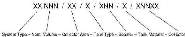
text_image
XX NNN / XX / X / XNN / X / XNNXX System Type - Nom. Volume - Collector Area - Tank Type - Booster - Tank Material - Collector| Variable | Categories | |
| System Type | AS | Active Systems (pumped) |
| HP | Heat Pump System Type | |
| TS | Thermosiphon, TS | |
| Nominal Volume | Nominal Storage Volume | |
| Collector Area | 20, 25, 40, 50, 60 | Nominal Collector Area ( m^2 × 10 ) |
| Tank Type | O | Open Circuit |
| C | Closed Circuit | |
| Booster | E | Electric |
| G | Gas | |
| XX | Booster Rating (kWx10 or Lpm) | |
| Tank Material/Designation | V | Vitreous Enamel |
| S | Stainless Steel | |
| Collector Type | E20BC, E25BC or E20AA | |
Table 1.4.1 System Model Number
For example, AS315/40/0/E36/V/E20AA:
1 Customer Information

A breach of this requirement may void the warranty in the event of damage caused by leaking due to frost or freezing.
1.6 Important safety information
All water heaters have the ability to produce hot water very quickly. To reduce the risk of scald injury it is recommended that a temperature control valve be fitted to the hot water supply pipe work. This valve should be checked every 6 months to ensure its operation and settings remain correct.
Check that the pressure & temperature relief valve drain pipe is not located where it can cause damage if hot water is discharged.

This water heater is not intended for use by young children, infirm persons, or persons lacking relevant skill or experience, without suitable supervision.
Children should be supervised to ensure they do not play with hot water taps or the water heater.
1.7 If the customer is away for a long period of time
If the system is not to be used for a period of a week or more during the summer months it is advisable to turn off the electricity supply to the booster and if practical, cover the solar collectors. If the solar collectors are not covered there is a possibility that the high temperature valve in the storage tank may open and disperse small amounts of hot water for a short period to reduce the storage tank temperature while you are away. This is a normal function and does not harm the system.
1.8 Water discharge through the pressure valve
All Envirosun solar water heaters have two pressure valves located within the system configuration. The cold water expansion control valve (ECV), located in the cold water
2 TROUBLESHOOTING
If there is not enough hot water we recommend that the following points are considered as part of the service call. The most obvious reasons for a lack of hot water could be one of the following.
2.1 Low solar energy input
If there have been prolonged periods of cloud or winter is approaching, it may be necessary to reconsider the permitted boosting time for time-clock controlled systems or to turn on the booster for systems with a booster isolation switch.
2.2 Solar collector shading
Often trees or other buildings can shade the solar collectors or there can be a dirt build-up on the glass cover. Trees should be cut back if possible or the system relocated if removal of the shading is not possible in the present location. If the glass is dirty this should be cleaned with standard domestic glass cleaner. If rainwater collection occurs from the same roof on which the solar water heater is located, do not use chemical cleaning agents to clean the collectors. Any spillage of these onto the roof could cause contamination of water in the rainwater tank.
2.3 AES (Booster) system not operating
For electric systems the fuse or circuit breaker supplying the AES System should be checked. If the time clock (where fitted) and the fuse or circuit breaker are operational and the water is cold, you can turn the booster isolator on and off to see if the electricity meter speed changes. If there is no change in speed, it indicates there may be a booster problem. Contact your authorised Envirosun dealer or installation service provider as soon as possible.
For gas systems the gas and electric supplies to the gas heater should be checked to ensure they are both on. If water temperature from the gas heater is below 70 °C and both
2.6 Water discharge from the frost valve
If your system has a frost valve fitted it will be located at the bottom corner of the collector. In temperatures that cause frost or freezing the valve will open and some water will discharge from this valve. There is nothing that needs to be done to the valve or the system, it is operating correctly. The water will stop discharging once the valve has warmed enough to close again, usually as the frost clears. Depending on the water quality level or solids that may accumulate in the system, the frost valve may be prevented from closing and sealing properly. If this occurs the system may need to be flushed clean and/or valve replaced.
Refer to section 1.5 on page 5 for more information on frost protection.
3 System Maintenance
The Envirosun solar water heater is designed so that there is little to do in the way of system maintenance.
Personally inspecting or servicing any part of the system is not recommended.
Should you decide that you want to inspect the roof mounted collectors, it is essential that you use all safety devices required to ensure your personal safety. Most importantly the electricity supply must be turned OFF.
3.1 Draining and flushing the system

The system must be completely drained of water before any plumbing work is commenced. This will prevent damage to the storage tank in the event of a vacuum or excessive pressure forming at the storage tank.
The Envirosun AS hot water system should be drained and flushed every five years during a major service of the unit.
- Turn off and isolate the power supply to the electrical element.
- Turn off the water supply to the water heater.
- Release excess pressure from the tank by manually opening the pressure & temperature relief valve.
- Disconnect the cold water supply pipe connection to the tank.
- Fit a 12 " flexible drain pipe to the cold connection at the tank. Place the open end of the drain hose in a location where it is safe for the hot water to drain away from the tank.
- Manually open the pressure & temperature relief valve which will allow air into the tank and the water within the tank will flow out via the flexible drain pipe fitted to the cold inlet connection. Hold the valve open until the tank is empty.
- To drain the collectors, disconnect the cold pipe from the bottom of the collector array.
3.4 Relief valves

The lever on the relief valves should be operated at least every six months. Failure to do so may result in failure of the tank. If water does not discharge freely from the valves they should be checked and possibly replaced. The relief valves and relief valve drain lines must not be blocked. Some water may discharge during each heating cycle
Every five year's all safety valves should be replaced to ensure continued life and operational safety of the system. In locations where the potable water has a Total Dissolved Solids (TDS) of greater than 600 ppm it is recommended to replace all safety valves every 3 years.
3.5 Anode
The high quality vitreous enamel lined low carbon steel tanks have a sacrificial anode for long tank life. This anode should be inspected every few years and be replaced when it has worn out. As a minimum it is recommended that the anode be changed every 5 years. In areas where the water quality characteristics exceed the values in Table 4.3.1, it is suggested that the anode be checked and replaced at more frequent intervals.
4 IMPORTANT INSTALLATION INFORMATION
4.1 Local Standards
The following standards and regulations must be taken into account when planning the installation of the Envirosun AS solar water heater system.
AS/NZS 3500.4.2 National plumbing and drainage code hot water supply systems – acceptable solutions.
• HB 263-2004 heated water systems plumbing industry commission.
- AS/NZS 3000 Electrical installations (known as the Australian/New Zealand wiring rules).
- Any local regulations that govern this type of installation.
Where these instructions and any local regulations are in conflict, the local regulations shall prevail.
4.2 Safety
Do not commence any aspect of this installation until you have satisfied yourself that all safety issues have been addressed.

This installation should only be performed by an approved professional with suitable experience and licenses, authorised by Envirosun to conduct the work.
It is imperative that installers adhere to Occupational Health and Safety Guidelines at all times. The installer is responsible for their safety and the safety of those around them.
4.3 Water Quality
Water supply from an unfiltered water source that may be highly conductive or have a high mineral content may void the system warranty.
Therefore, to ensure water quality guidelines are met, the following characteristics should not be exceeded.
4 Important Installation Information
4.4 Pressure Reducing Valve
Where the mains water supply pressure is likely to exceed 550 kPa at any time, a 500kPa pressure reducing valve that complies with AS1357 must be fitted to the inlet of the hot water system.

This is essential to safeguard the appliance and ensure correct operation.
A breach of this requirement may void the warranty in the event of damage caused by excessive pressure.
4.5 High wind or cyclonic areas
The standard mounting system is sufficient for mounting most standard roof installations of either metal or tile roof construction. It may be necessary to use the cyclone mounting system if one of the following applies:
- The collector must be installed 1m (recommended) to 0.5m (minimum) of a roof edge or peak.
- The installation has minimal shielding from surrounding buildings and trees, or is located on a hill or similar locations that may cause high wind effects (refer to Terrain Categories, Topographic Effects & Shielding Factors in AS 1170.2: 2002, or consult a structural engineer).
- The installation is on a roof with a pitch greater than 30^ .

If the solar water heater is installed in an area classed as Cyclone Region C or D according to AS 1170.2: 2002, the standard mounting systems must not be used.
Please consult a structural engineer for advice on ensuring the installation will comply with local building codes and regulations.
4.6 Piping material

Envirosun recommends the use of copper pipe, certified to AS1432 Class C, for use in the flow and return lines to the solar water system.
4.8 Legionella requirements
The Australian Standards require that a water heater system provide a means to inhibit the growth of the Legionella bacteria in potable water.
If the system is installed with an approved Gas AES, with the outlet temperature set to 70^ C, then this requirement is satisfied.
If the system is installed with an Electric AES, then one of the following requirements must be met:
- At least 45% of the storage volume is heated to 60°C daily. This can be achieved by leaving the AES permanently on.
- At least 90% of the storage volume is heated to 60^ C for 32 minutes in each 7 day period. This will require any timing device or manual control to be adequately set-up or operated.
4.9 Roof location selection
There are six major factors to consider when selecting the solar collector installation location:
4.9.1 Collector orientation
For optimum performance, the solar collectors need to face the equator (in southern hemisphere this is north and in the northern hemisphere this is south). Installations orientated at angles of up to 45^ away from the equator do not have a major effect on the annual solar output. Consequently, roof locations which face less than 45^ away from the equator are acceptable. If the collectors are installed with an east facing bias the best solar input is achieved in the morning and if there is a west facing bias the best solar input is in the afternoon.
4.9.2 Shading
Careful site inspection is required to ensure the selected location is not subjected to shading from adjacent trees or buildings throughout the day, but particularly between 9am and 3pm, the highest solar input times. Shadows are longer in winter than in summer so a site that is free of shadows from adjacent objects in summer may have some shadows in winter.
4.9.3 Storage tank location
The solar water heater should be located as close as possible to the location which uses the most hot water e.g. the bathroom or kitchen. This is to reduce energy losses which may occur if the pipe work between the solar water heater and the point of usage is too long.
4.9.4 Collector inclination
To achieve optimum performance the solar water heater should be installed on a roof pitch of greater than 10^ and less than 30^ . Installations on a roof where the roof pitch is greater than 30^ will require additional support. If the roof pitch is less than 10^ , the system will require a mounting frame to increase the pitch above 10^ . Air can accumulate in installations below 10^ and may not circulate effectively. Additionally the collector glass will not self-clean during rainy periods.
4.9.5 Roof structure
Ensure the roofing material and roof structure are capable of supporting the full load of the collectors and trades personnel during installation. The structure should be capable of supporting a 250kg point load. If this is not the case, additional bracing must be installed before proceeding with the installation.
The Envirosun AS hot water system can be installed on metal or tile roofs.
4.9.6 Roof area
To ensure adequate working access for the installation and future maintenance, an area of not less than 500mm should be left completely around the system.
5 Dimensions and Technical Data
5 DIMENSIONS AND TECHNICAL DATA
5.1 Collector and Tank Dimensions
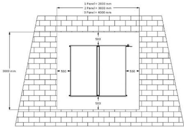
text_image
1 Panel= 2000 mm 2 Panel= 3000 mm 3 Panel= 4000 mm 500 3000 mm 500 500 500Figure 5-1 Collector Installation Area
5 Dimensions and Technical Data
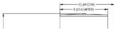
| Model Number | Dimensions (mm) | ||||||
| A | B | C | D | E | F | G | |
| AS315/25/O/*/E25BC | 1754 | 617 | 1521 | 195 | 695 | 838 | 692 |
| AS315/40/O/*/E20BC | 1754 | 617 | 1521 | 195 | 695 | 838 | 692 |
| AS315/40/O/*/E20AA | 1754 | 617 | 1521 | 195 | 695 | 838 | 692 |
| AS315/50/O/*/E25BC | 1754 | 617 | 1521 | 195 | 695 | 838 | 692 |
| AS400/40/O/*/E20BC | 1703 | 705 | 1445 | 219 | 719 | 642 | 780 |
| AS400/40/O/*/E20AA | 1703 | 705 | 1445 | 219 | 719 | 642 | 780 |
| AS400/50/O/*/E25BC | 1703 | 705 | 1445 | 219 | 719 | 642 | 780 |
| AS400/60/O/*/E20BC | 1703 | 705 | 1445 | 219 | 719 | 642 | 780 |
| AS400/60/O/*/E20AA | 1703 | 705 | 1445 | 219 | 719 | 642 | 780 |
Table 5.1.1 System dimensions
5.2 Parts Kit Details
All systems require a PM-600-C
| Model Number | Tank | Collector | Connection Kit | Mounting Kit |
| AS315/25/O*/E25BC | VE315/E24/V | E25BC | PK-3205 PK-3100 | PK-1104 |
| AS315/40/O*/E20BC | VE315/E24/V | E20BC | PK-3205 PK-3102 | PK-1105 |
| AS315/40/O*/E20AA | VE315/E24/V | E20AA | PK-3205 PK-3102 | PK-1105 |
5.3 System Weights
| Tank | Material | Weight – Empty (kg) | Weight – Full (kg) |
| VE250/E24/V | Vitreous Enamel Mild Steel | 81 | 339 |
| VE315/E24/V | Vitreous Enamel Mild Steel | 99 | 420 |
| VE400/E24/V | Vitreous Enamel Mild Steel | 113 | 533 |
Table 5.3.1 AS Tank Weights
| Collector | Weight – Empty (kg) | Weight – Full (kg) |
| E20BC | 35.0 | 36.7 |
| E25BC | 42.8 | 44.8 |
| E20AA | 36.6 | 38.3 |
Table 5.3.2 Collector Weights
6 Installation Instructions
6 INSTALLATION INSTRUCTIONS
Before commencing the installation of the solar water heater system, please ensure you have familiarised yourself with the requirements of Section 4 Important Installation Information.

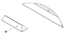
Carefully remove all packaging and protective coatings and dispose of them in an appropriate manner. This includes the plastic core-strip from the back of the collector when mounted on a pitch frame, the plugs from the collector and storage tank connection pipes.
6.1 Installing the collectors
text_image
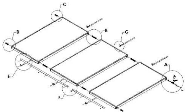
Technical diagram of a multi-layered structural assembly with labeled components A through G and directional arrows indicating flow or movement.Figure 6-1 Collector Installaon General Assembly
fitted to collector. Tighten the compression nuts of the collector connector fittings (Detail B, 60-1002), taking care not to twist the copper tubes of the collector. Make sure you use correctly sized spanners and that the centre nut is held steady whilst the compressing nuts are tightened.
- Move the collectors so that they are centrally located on the collector mounting rail.
- Screw fix the collector rail to the collector/s using the screws supplied. (Detail E, 75-3047)
- To fix the top of the collectors to the roof, take the remaining mounting straps (Detail G, 60-4011) and place as centrally as possible at the top of each of the collectors with the strap fixing ends pointing up the roof.
- Screw fix the collector straps to the collector using the screws supplied. (Detail G, 75-3047)
- Finally, screw fix the collector straps to the roof rafters to complete the collector mounting.
- Steps 14 to 19 relate only to the 3 Panel Array:
- Loosely fit the two collector connectors (Detail B, 60-1002) to the two copper tube spigots on the right side of the second collector.
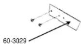
- Locate a roof truss which is under the third panel extension rail (Detail F, 60-3029), as near as possible to the outer edge of the rail. Clip one collector strap (Detail E, 60-4011) to the extension rail where the truss will pass under the extension rail.
- Screw fix the extension rail to the two panel collector rail that is already installed, using the self-drilling screws supplied (Detail F, 75-3047) The extension rail is provided with grooves and pilot holes for correct positioning.
text_image
60-1063 60-1043 60-1074
text_image
60-1002
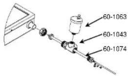
- Assemble and install the Hot Connection Union assembly (Detail A) as follows;
- Take the temperature well (Detail A, 60-1043) and slide it onto the copper spigot at the top right of the collector array. Tighten the assembly taking care not to twist the copper tubes of the collector. Make sure you use correctly sized spanners and that the nut is held steady whilst the compressing plug is tightened.
- Wind five turns of thread tape onto the 12 " BSP thread of the Temperature Well
- Insert the Temperature Well into the 12 " BSP socket end of the Hot Connection Union (Detail A, 60-1074) and tighten normally. Take care not to over tighten.
- Wind five turns of thread tape onto the 18 BSP thread of the Air Bleed Valve.
- Screw fit the Air Bleed Valve (Detail A, 60-1063) into the top 38 " BSP socket and tighten
- Open the Air Bleed Valve by turning the knob on top anti-clockwise 1 ½ turns from closed.
- Connect the hot return pipe using the 12 "BSP socket on the side to the Hot Connection Union assembly. The piping must not be higher than the Air Bleed Valve at any point and must have a continuous fall to the tank.
- Slide the 34 BSP Compression Union Assembly (Detail D, 60-1003) to the bottom left hand corner connection of the array. Tighten the assembly taking care not to twist the copper tubes of the collector. Make sure you use correctly sized spanners and that the nut is held

text_image
75-3047 60-4011Figure 6-6 Detail E

6 Installation Instructions
- Connect the second 12 " insulated copper tube to the Hot Connection assembly at the top right hand corner connection of the array and run down to the ground mounted storage tank location. This tube is known as the Collector Hot Connection.
- Connect a 2 core cable to the two wires of the black insulated temperature sensor supplied with the Pump Module (PM-600). Fully insert the temperature sensor into the temperature sensor well of the hot connection union assembly. Secure in place with the P-Clip and screw provided. Run the cable down to the ground mounted storage tank location. This sensor is known as the Collector Temperature Sensor.

Care must be taken to ensure that all roof penetrations are sealed to prevent water ingress and to comply with all local regulations.
7 CONNECTIONS AT THE STORAGE TANK
7.1 Connections for the PM-600
- Apply thread tape or a suitable sealant to the thread of a 34 " BSP to 12 " compression union. Screw the union into the top (outlet) socket on the right side of the storage tank. Fasten the Collector Hot Connection (Section 6.3, Step 2) into the compression union.
- Apply thread tape or a suitable sealant to both threads of the 34 " to 34 " BSP brass nipple (P/No 60-5067) and screw into the bottom (inlet) socket, on the right side of the storage tank.
- Screw the All 34 " Tee (60-5015) into the 34 " nipple and position the branch faces upwards.
- Apply thread tape or a suitable sealant to the thread of the 34 " x 12 " bush (60-5008) and screw into the end of the tee piece.
- Apply thread tape or a suitable sealant to the thread of the temperature well (60-1163) and screw into the reducing bush.
- Apply thread tape or a suitable sealant to the large thread of the 34 " to 12 " BSP brass fitting (P/No 60-5066) and screw into the tee branch.
- Take the PM-600 module and fasten a Gland Union (P/No 60-1032) to the Ball Valve (P/No 35-8008) on the lower pump fitting and the Check Valve (P/No 35-8009) on the upper pump fitting.
- Apply thread tape or a suitable sealant to one end of the 12 " BSP brass union (P/No 60-5065) and fasten it into the lower Gland Union attached to the Ball Valve.
- Loosely attach one end of the 225mm Flexible Connector (P/No 60-1115) to the brass nipple on the PM-600 module. Loosely attach the other end to the branch fitting of the tee piece at the bottom of the storage tank.
- With the flexible connector loosely fitted, move the pump module into position on the storage tank and fix in place with the self-drilling screws supplied (P:/No 75-3047). Ensure the flexible connector is not kinked in any way, and the pump module is vertical. Tighten the loose nuts on the flexible connector.
7 Connections at the Storage Tank
- Make the Collector Cold Connection (Section 6.3, Step 2) to the upper pump fitting of the PM-600 module.
- Open the Ball Valve (P/No 35-8008) by turning the screw slot until it is vertical.
- Turn on the mains water supply to the unit and fill the storage tank as normal.
Check for leaks in the system and fix as required.
7.2 Plumbing Connections
The Storage Tank is installed and connected to the plumbing installation as normal and detailed in the Envirosun installation instructions supplied with the water heater. The household plumbing connections should be made to the tank socket fittings on the left side of the storage tank. This leaves the right side fittings free for connection to the solar collector system.
7.2.1 Cold water connection

A check valve and a stop cock must be fitted to the cold water supply pipe work.
-
The cold water connection is made at the connection marked "Cold Water Inlet".
-
Where the water supply pressure is greater than or likely to exceed 550kPa at any
time, a 500 kPa pressure reducing valve must be fitted to limit the supply pressure.
A breach of this requirement may void the warranty in the event of damage caused by excessive pressure.
7.2.2 Cold water expansion relief valve
Fit the 600 kPa expansion control valve, supplied in the Parts Box, in the cold water supply pipe after the check valve, stop cock and (if required) pressure reducing valve.
7.2.3 Hot water connection
Connect the hot water supply to the storage tank 34 " BSP outlet connection located on the
8 Electrical Connections
8 ELECTRICAL CONNECTIONS
8.1 Electrical connection for Electric AES (Booster)
For safe performance this water heater is fitted with a thermostat and an over temperature cut-out. These devices should not be tampered with or removed.

Do not operate this water heater without the electrical thermostat and over temperature cut-out in the circuit.
The electric element is only connected in models using an electric AES system. No connection is made to the electric element for gas AES systems.
The electrical booster requires a 220 – 250 volt single phase AC power supply with a capacity suitable for the kilowatt rating of the element selected for the application. For example, a 2.4 kW element requires a 10 amp supply capacity, a 3.6 kW element requires 15 amp supply capacity.
Electrical entry for the electric AES is achieved via a 20mm opening adjacent the element surround.
A cable gland with orange circular cable, or 19mm conduit with 3 core TPS cable must be used to make electrical supply to the unit.

The power supply must be protected by an individual fuse or circuit breaker rated to suit the booster size.
The supply to the solar water heater can be operated directly from the switchboard or via a remotely mounted switch or time clock as requested by the customer. The correct
8.1.1 Electrical circuit diagram

text_image
Red Black N A1 Element EarthFigure 8-1 Electrical circuit diagram
8.2 Electrical Installation for the PM-600
From the mains electrical connection, install a permanent 230 to 250 volt, 50 Hz external GPO in a suitable position near the pump module. The pump module draws a maximum 50 watts at full load.
The temperature sensors should not be in direct contact with fluid. Always use immersion sleeves. Take the collector temperature sensor cable assembly and attach to the panel-mounted, 2 way connector. This plug will only fit one way. The tank temperature sensor cable is hard wired to the module, and exits the case through an M12 cable gland. Should extra cable length be required, there is slack inside the module. Remove the cover, loosen the cable gland, and pull through extra cord as required. Re-tighten cable gland and replace cover.

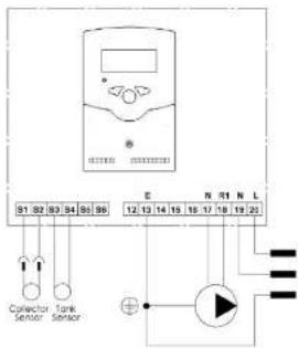
text_image
91 82 83 84 85 86 E N R1 N L Collector Sensor Tank Sensor + N 17 18 19 20Figure 8-3 PM-600 Wiring Diagram
8.2.1 Controller Setting

This information is for servicing only. Changing the optimal factory settings will void the warranty. It is not recommended that you run the system in manual for extended periods.
If there is a need to change a field you have noticed to be incorrect:
- Turn on the power supply and wait 15 seconds.
- Press and hold down Button 1 until "SEt" appears on the display screen.
- Using Buttons 1 & 2 to scroll, move up and down the channels until you reach the one requiring amendment.
- Change the channel:
Figure 8-4 Controller funcons
| Field | Value |
| DO | 10 |
| DF | 1 |
| SX | 70 |
| CL | 200 |
| CX | 190 |
| CN | 4 |
| FN | 3 |
| MM | 2 |
Table 8.2.1 Controller sengs
8.3 Gas AES installation instructions
All gas work must comply with local regulations including AS5701/AG601 and AS/NZ 3500.4
All gas work must be conducted by a suitability licensed gas fitter.
Installation of the gas heater must be installed in accordance with the installation instructions supplied with it.
Envirosun systems only use approved Gas Heaters.
Particular attention must be given to the gas supply system to ensure the there is a sufficient gas supply available to the gas heater when operating at full output burner rate.
8.3.1 Approved Gas AES models
Gas heater models used with Envirosun solar water heater systems must be certified to all local requirements, be automatic ignition and have full flame modulation.
The temperature setting of the gas AES must be permanently set to 70°C.
9 COMMISSIONING & CUSTOMER HAND OVER
9.1 Commissioning
When all connections have been completed the solar water heater can be filled with water.

- Before turning on the cold water supply to the system, open one hot tap within the household to release air from the system during the filling process. Do not leave the open tap unattended during the filling process.
- Turn on the cold water supply and wait for the system to fill.
- When water flows from the open hot tap without air bursts then the hot tap can be closed. This will now pressurise the solar water heater system.
- Once the system is pressurised, all connections on the water heater must be checked for leaks and repaired if necessary.
- When the system is proven water tight, power and/or gas can be applied to the AES system.
- To test that the element is operational turn the circuit breaker in the switch board on and off, you should see the power meters speed change during this action.
- For gas AES systems, turn on a hot water tap and the gas heater will ignite provided the water temperature is less than 70 °C .
9.2 Customer Hand Over
The solar water heater is now fully operational.
Once the solar water heater is commissioned and you are confident it is operating correctly, complete the installation details on the carbon copy sheet at the beginning of the Owner's Manual. Please remove the Envirosun (blue) and the installer (pink) copy.
Please hand the owner the Owner's Manual and Gas Heater Manual (if gas AES is used).
Before leaving the installation, ensure that the customer is fully aware of the systems operation and whom to contact should there be any questions in the future.
Thank you for installing our world class Envirosun solar water heater.
10 WARRANTY
10.1 Warranty terms
This warranty is given by Solar Now International Pty Limited ACN 166 500 787 (Envirosun) in relation to Envirosun Solar Hot Water Systems (the Product).
The benefits conferred by this warranty are in addition to all other legal rights and remedies of the Customer in respect of the Product. Given installation and application is in accordance with the manufacturer's specifications and instructions, the Product and components are warranted by Envirosun for the cost of labour and components in the event of defects arising from faulty materials and/or workmanship in accordance with the warranty conditions and exclusions stated in this document.
Where the Product is installed outside the boundaries of a Capital Cities Metropolitan area or where the Product is installed outside a 25km radius of a Envirosun Dealer business address, the cost of transport, insurance and travelling will be charged to the consumer.
For all new Product purchases through public sales auctions, internet and/or other electronic sales auctions or remote offerings, the warranty for the Product is the responsibility of the dealer or reseller of the Product, and not of Envirosun.
Warranty of the Product will remain with the Product for the warranty coverage period.
10.2 Warranty conditions
The initial point of contact for all Warranty claims is the Envirosun Dealer from whom the Product was purchased.
All warranty claims must be reported to Envirosun no later than 14 days from the date the fault is reported to the Envirosun Dealer. All terms of this warranty are effective from the date of installation of the Product and the attending service person reserves the right to verify this date by requesting a copy of the certificate of compliance ^1 or installation record issued by an appropriately qualified installer prior to the commencement of any warranty work. The Product must have been installed commissioned, serviced, repaired and

Any work required to gain reasonable access to the appliance will be chargeable to the customer by the attending service person including, but not limited to, removal of cupboards, doors, walls, or the use of special equipment to move components to floor level.
The Product is covered for the indicated period from the date of installation. Should a part of the complete Product be replaced during this period, only the balance of the original warranty will continue to remain effective.
This warranty applies to the Product when it is connected directly to a reticulated water supply from a state approved water utility.
This warranty does not apply if the Product is connected to any alternative water supplies if the water chemistry and impurity levels of alternative water supplies exceed the limits specified in Table 4.3.1 Water quality requirements on page 11.
Examples of alternative water supplies include private bore water, water from private dams and water supplied from a reticulated water supply but where the water chemistry is deliberately altered before supplying the water heater. Should the Product be installed in a regional location where regular flushing is required due to sediment build-up, the drain cock for flushing must be fitted at the time of installation at customer expense. A warranty will apply to rain water tanks, as alternative water supply, ONLY in circumstances where rain water is filtered and free of any physical or sediment debris and water quality does not exceed the limits specified in Table 4.3.1 Water quality requirements on page 11.
Component manufacturers are at liberty to alter the design or construction of the components notwithstanding that the Product may have been sold by description or sample, even though alterations made have been introduced from the date of contract and the date of delivery provided that the Products are of the same or similar quality and are fit for the purposes for which they are purchased. Such alterations shall not constitute a defect in design or construction under this warranty.
Envirosun reserves the right to alter the design or construction of the Product within allowance of the relevant Standard(s), industrial and State and Territory legislation without notice. Envirosun warrants to the original purchaser, or for Product purchased from a Reseller, to the original end user, that the Product will be free from any defects in materials

Envirosun offers 12 months comprehensive warranty for the Product including parts and labour. In addition to 12 months comprehensive warranty, Envirosun offers 4 years warranty on tanks, element flange subassembly (excluding element), collectors, seals and mounting frame for the Product as shown in Table 10.2.1 below.
Closed circuit tanks must be installed and charged in accordance with Envirosun requirements and use.
Envirosun transfer fluid to be warranted against frost and freezing.
| Component | Warranty coverage | |
| Parts Warranty | Labour Warranty | |
| TS & TS Plus Tank (roof mounted) | 5 year | 5 year |
| AS Tank (ground mounted) | 5 year | 1 year |
| Element Flange subassembly TS Systems | 5 year | 5 year |
| Collector | 5 year | 5 year |
| Seal, Neck Ring | 5 year | 5 year |
| Mounting Frame | 5 year | 5 year |
| Element | 1 year | 1 year |
| Anode (TS Range only) | 1 year | 1 year |
| Thermostat, Solar | 1 year | 1 year |
| Valves and plumbing accessories | 1 year | 1 year |
| Heat Exchanger | 1 year | 1 year |
| Vessel Expansion | 1 year | 1 year |
| Pump^2 3 | 1 year | 1 year |
| Sensors | 1 year | 1 year |
10.3 Warranty Exclusions
The following exclusions may cause the warranty to become void, and may incur a service charge and cost of parts that may be required.
- Accidental damage, failure due to misuse, abuse and accidents.
- Failure due to incorrect installation and/or attempts to repair the Product other than by a Envirosun Dealer and/or approved service personnel.
- Failure to install, commission, service, repair and remove the Product in accordance with the manufacturers installation instructions, current AS/NZS 3000, AS/NZS 3500, AS/NZS 5601, local regulations and municipal building codes by persons authorised to do so.
- Failure due to use of parts other than Envirosun branded/approved parts.
- Where the solar collector leaks or fails to operate normally due to frost or freezing, unless the Product has been installed under a Sustainability Victoria program requiring frost warranty or other such similar State administered program.
- When frost or over-heating damage arises as a result of the power supply being disconnected, turned off or cut to an active system (pump module).
- Damage and/or breakage to the collector glass.
- Where the Product component has failed directly or indirectly as a result of excessive water pressure, negative pressure (partial vacuum), corrosive atmosphere, faulty plumbing and/or electrical wiring, or major variations in electrical energy supply.
- Where the water stored in the cylinder exceeds at any time levels as per Table 4.3.1 Water quality requirements on page 11.
- Any serial tags/stickers on any of the components are removed or defaced.
- The Product is relocated from its original point of installation.
- This warranty does not cover:
- claim for damage to walls, foundations, gardens, etc. or any other consequential loss or inconvenience either directly or indirectly due to leakage from the solar water heating system or any other matter related to the system or its operation.
- the effects of sludge/sediment as a result of connection to a water supply from suitably filtered or treated sources e.g. spring, dam, bore or river.
11 CONTACT DETAILS
For further information, please call one of the following phone numbers from anywhere in
Australia:
For service, installation information or warranty 1300 825 143
For sales or new product information 1300 314 173
Head Office:
Solar Now International Pty Ltd
460 Victoria Road
Malaga WA 6090