RD30BG6SS - Cooker VIKING - Free user manual and instructions
Find the device manual for free RD30BG6SS VIKING in PDF.

User questions about RD30BG6SS VIKING
0 question about this device. Answer the ones you know or ask your own.
Ask a new question about this device
Download the instructions for your Cooker in PDF format for free! Find your manual RD30BG6SS - VIKING and take your electronic device back in hand. On this page are published all the documents necessary for the use of your device. RD30BG6SS by VIKING.
USER MANUAL RD30BG6SS VIKING
Rear Trim Accessories
| MODELS BACKGUARD HIGH SHELF CURB BASE | |||
| VGIC5301VGCC530C/VDSC530C/VESC530C/VISC530VGRT530C/VER530C/VIR530 | P30BG8SS B304 | H24SS P30CBF4SS | N/A |
| VGCC536C/VDSC536VGIC5361VGRT536 | P36BG8SS B36H | S24SS P36CBF4SS | N/A |
| VGCC548C/VDSC548VGRT548 | P48BG8SS B48H | S24SS P48CBF4SS | N/A |
| VGCC560C/VDSC560 | P60BG8SS B60H | S24SS P60CBF4SS | |
| VGR530C/VDR530VGIC5302VRT530 | BG8530SS HS24 | S30SS P30CBF4SS | |
| VGR536C/VDR536VGIC5362 | BG8536SS HS24 | S36SS P36CBF4SS | |
Rear Trim Accessories
All rear trim devices are installed in the same basic way.
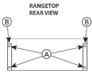
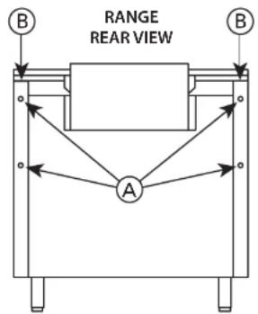
ATTACHING REAR TRIM (Illustration I)
Grasp the trim on each end and carefully place in the channels (B) located at each rear corner of the product. Align the screw holes (A) at each end of the trim device with the holes (A) in each rear channel of the product. Secure with the 4 enclosed screws.
flowchart
graph TD
    A["A"] --> B["B"]
    A --> C["Point 1"]
    A --> D["Point 2"]
    A --> E["Point 3"]
    A --> F["Point 4"]
    A --> G["Point 5"]
    style A fill:#f9f,stroke:#333
    style B fill:#ccf,stroke:#333
    style C fill:#cfc,stroke:#333
    style D fill:#fcc,stroke:#333
    style E fill:#cff,stroke:#333
    style F fill:#ffc,stroke:#333
text_image
RANGE REAR VIEW AATTACHING SHELF ON HIGH -SHELF (Illustration 2)
Place the top rolled edge (X) over the front lip of the high-shelf back trim and secure with the 4 enclosed screws, two at each end. CAUTION: Do not place heavy pans and pots on the High Shelf or light flammables liquids.
HIGH SHELF
Rear Trim Accessories
ATTACHING BACKGUARD (Illustration 3)
Backguards come equipped with Nylon Spacers (See Figure 1), which are needed to space the range off a combustible wall a prescribed safe distance.
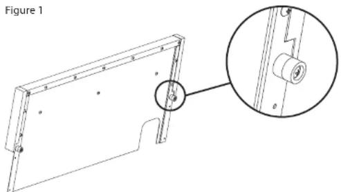
natural_image
Technical line drawing of a mechanical component with an inset close-up view (no text or symbols)These spacers can also be removed if used with any of the models* listed below:
• C/VGCC530
*If you have one of these models, the spacers are not
• C/VDSC530
required, even if with a combustible wall.
• C/VDSC536
• C/VGRT530
• C/VGRT536
C/VGCC560 ranges require that two 1" standoff spacers be attached to the back of the range when using a range with a backguard against a combustible surface. (See Figure 2)
Figure 2
natural_image
Technical line drawing of a mechanical component with circular features and structural supports (no text or symbols)Rear Trim Accessories
ATTACHING ISLAND TRIM (Illustration 4)
flowchart
graph TD
    A["A"] --> B[" "]
    A --> C[" "]
    A --> D[" "]
    A --> E[" "]
    A --> F[" "]
    style A fill:#fff,stroke:#000
    style B fill:#fff,stroke:#000
    style C fill:#fff,stroke:#000
    style D fill:#fff,stroke:#000
    style E fill:#fff,stroke:#000
    style F fill:#fff,stroke:#000
IMPORTANT: USE OF ISLAND TRIM WITH AND WITHOUT 6" (15.2 CM) CLEARANCE.
Normal installation for island trim on either a range or rangetop is in an island/peninsula or where there is a minimum clearance of 6" (15.2 cm) to any type of wall at the rear of the unit. Ranges and rangetops with an island trim installation can be installed at zero clearance to the rear wall as long as the wall is non-combustible. The responsibility for ensuring that the rear wall is non-combustible and heat resistant lies with the individual owner and/or end user. Only in those cases where the island trim is installed with 6" (15.2 cm) of minimum clearance to a rear wall, or when a truly non-combustible material is used, will the warranty apply. In no case will Viking Range, LLC accept responsibility for any claims which may result from heat damage against a rear wall, including cosmetic damage. It is the total responsibility of the owner/end user to ensure that the material utilized in such applications is not only non-combustible, but is also truly heat-resistant.
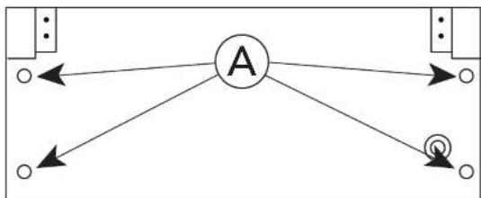
CURB BASES
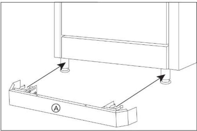
STANDARD CURB BASE FRONT
- The standard curb base front (A) is completely assembled.
- Remove the assembly from the carton and simply clip onto the front range legs.
- The assembly is adjustable about 2" (5.1 cm) front to back so that alignment with the cabinet toe front is possible. Loosen
brackets on each side, but allow snug fit. Clip assembly onto range legs; determine front to back setting; remove, tighten bolts, and reattach.
natural_image
Technical line drawing of a mechanical assembly with mounting holes and a base plate (no text or symbols)ALTERNATE CURB BASE VIEW
CURB BASES
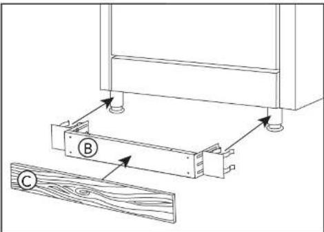
CUSTOM CURB BASE FRONT
- Remove the standard curb base front assembly from the carton.
- Remove the front (A) from the mounting assembly (B).
- Attach locally supplied front (C) to the mounting assembly (B) ad simply clip onto the front range legs.
Important Note: The locally supplied front must not be any taller than 3-1/8" (7.9 cm) tall. Fronts taller than 3-1/8" (7.9 cm) could obstruct the airflow.
- The assembly is adjustable about 2" (5.1 cm) front to back so that alignment with the cabinet toe front is possible. Loosen brackets on each side, but allow snug fit. Clip assembly onto range legs; determine front to back setting; remove, tighten bolts, and reattach.
text_image
Technical diagram showing a wooden frame assembly with labeled components A, B, and CImportant Note: The range must be installed as specified in the range installation guide for proper airflow when using the standard curb base.