CAP1133 - Electronic component Microchip - Free user manual and instructions
Find the device manual for free CAP1133 Microchip in PDF.

User questions about CAP1133 Microchip
0 question about this device. Answer the ones you know or ask your own.
Ask a new question about this device
Download the instructions for your Electronic component in PDF format for free! Find your manual CAP1133 - Microchip and take your electronic device back in hand. On this page are published all the documents necessary for the use of your device. CAP1133 by Microchip.
USER MANUAL CAP1133 Microchip
CAP1xxx Evaluation Board User's Guide
text_image
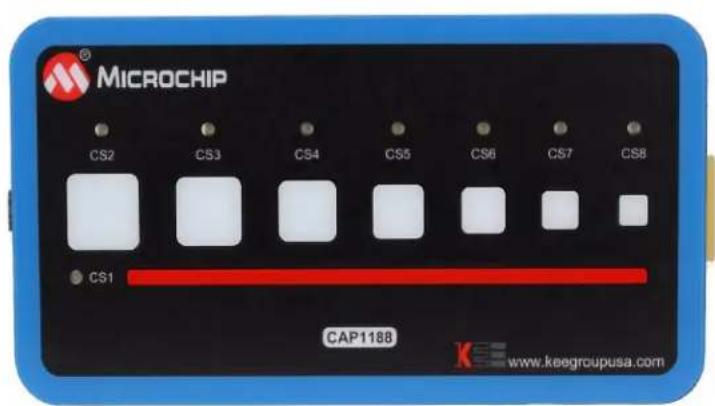
MICROCHIP CS2 CS3 CS4 CS5 CS6 CS7 CS8 CS1 CAP1188 www.keegroupusa.com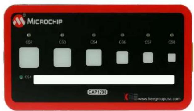
text_image
MICROCHIP CS2 CS3 CS4 CS6 CS7 CS8 CS1 CAP1298 www.keegroupusa.com1 Overview
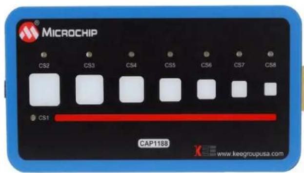
This document provides a description of the software and hardware used to demonstrate the features of the Microchip CAP1xxx Family of RightTouch™ multiple-channel capacitive touch controllers and LED drivers. Two evaluation boards are covered in this User's Manual. The CAP1188 evaluation board contains the largest, full-featured version of the CAP11xx family. The other devices in this family are the CAP1166, CAP1128, CAP1126, CAP1133, and CAP1106. Likewise, the CAP1298 evaluation board contains the largest, full-featured version of the CAP12xx family. The other devices in this family are the CAP1296, CAP1293, CAP1208, CAP1206, and CAP1203.
1.1 References
Readers should be familiar with or have access to the datasheet for the device and the schematic for the evaluation board.
The datasheet is included with the CD provided with the evaluation board, and can also be downloaded from the Microchip website at http://www.microchip.com/mtouch.
The schematic is included with the CD provided with the evaluation board.
1.2 The RightTouch Evaluation System
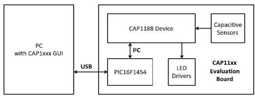
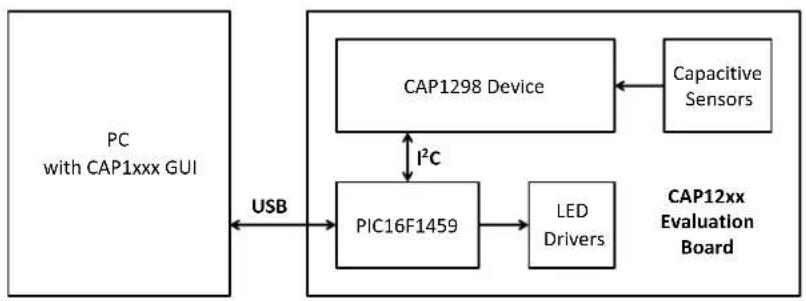
The evaluation system has three major parts, as shown in Figure 1.1:
■ Customer-provided Windows PC
■ CAP1xxx graphical user interface (GUI) software (based on National Instruments™ LabVIEW™ software)
■ CAP1xxx Evaluation Board - either the CAP1188 or CAP1298 versions (see Figure 1.2)
flowchart
graph TD
    A["PC with CAP1xxx GUI"] -->|USB| B["PIC16F1454"]
    B <-->|I²C| C["CAP1188 Device"]
    C <--> D["LED Drivers"]
    D --> E["Capacitive Sensors"]
    E --> F["CAP11xx Evaluation Board"]
flowchart
graph TD
    A["PC with CAP1xxx GUI"] -->|USB| B["PIC16F1459"]
    B --> C["LED Drivers"]
    C --> D["CAP12xx Evaluation Board"]
    D --> E["Capacitive Sensors"]
    E --> F["CAP1298 Device"]
    F -->|I²C| B
Figure 1.1 CAP1xxx Evaluation System
text_image
MICROCHIP CS2 CS3 CS4 CS5 CS6 CS7 CS8 CS1 CAP1188 www.keegroupusa.com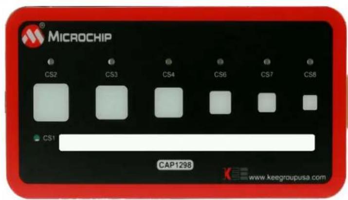
text_image
MICROCHIP CS2 CS3 CS4 CS6 CS7 CS8 CS1 CAP1298 www.keegroupusa.comFigure 1.2 CAP1xxx Evaluation Board Top View
1.2.1 Capacitive Sensing Device on the Evaluation Board
The CAP1188 device was chosen for the evaluation board because it has the most sensors and LEDs in the CAP11xx family.
Note: The CAP1114 and CAP1214 devices, each with 14 sensors and 11 LED drivers, contain additional features such as slider support which will be highlighted in their own evaluation board.
The CAP1298 device was chosen for the evaluation board because it is the superset device in the family, meaning it has the most sensors and features in the CAP12xx family including the signal guard.
The CAP1188, CAP1166, CAP1128, CAP1126, CAP1133, and CAP1106 are similar, with the exception of the number of capacitive sensor inputs and LED drivers, as shown in Table 1.1.
Table 1.1 CAP11xx Device Differentiation
| DEVICE NUMBER OF LED DRIVERS | NUMBER OF CAPACITIVESENSOR INPUTS | |
| CAP1133 3 3 | ||
| CAP1106 0 6 | ||
| CAP1126 2 6 | ||
| CAP1166 6 6 | ||
| CAP1128 2 8 | ||
| CAP1188 8 8 |
The CAP1298, CAP1296, CAP1293, CAP1208, CAP1206, and CAP1203 part of the same family and so have a very similar feature set, with the major exception being of the number of capacitive sensor inputs and the guard output, as shown in Table 12.
Table 1.2 CAP12xx Family Device Differentiation
| DEVICE | NUMBER OF CAPACITIVE SENSORS | GUARD |
| CAP1203 3 No | ||
| CAP1293 3 Yes | ||
| CAP1206 6 No | ||
| CAP1296 6 Yes | ||
| CAP1208 8 No | ||
| CAP1298 8 Yes |
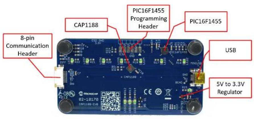
1.2.2 Major Components on the Evaluation Board
Figure 1.3 shows the component side of the CAP1188 evaluation board and highlights some of the important components.
text_image
CAP1188 PIC16F1455 Programming Header PIC16F1455 USB 8-pin Communication Header CAP1188 USB 5V to 3.3V Regulator
text_image
CAP1298 8-pin Communication Header PIC16F1459 Programming Header PIC16F1459 USBFigure 1.3 Evaluation Board Component Side View
2 Software and Hardware Installation
To begin using the CAP1xxx evaluation board, you only need to supply power by plugging in the USB connector. However, in order to further evaluate the features of the CAP device, the CAP1xxx GUI must be installed on a Windows-based computer with a USB port.
2.1 GUI Software Installation
Begin by inserting the CD provided with the evaluation board into the computer. Run the Setup.exe program located in the root directory of the CD. This steps through the CAP1xxx GUI installation, which takes less than a minute. Figure 2.1 shows the initial installation screen, which displays briefly as the setup program loads.

text_image
CAP1xxx GUI Ver. 2.0 This will install or update the CAP device GUI from Microchip Technology Inc. << Back Next >> CancelFigure 2.1 Software Installation Step 1
Click Next in the Destination Directory window, shown in Figure 2.2. For proper operation, the files must be installed in the default locations. The default location for the software files is C:\Program Files\Microchip\Microchip CAP1xxx GUI and for the LabVIEW™ software is C:\Program Files\National Instruments.

text_image
CAP1xxx GUI Destination Directory Select the primary installation directory. All software will be installed in the following locations. To install software into a different location, click the Browse button and select another directory. Directory for CAP1xxx GUI C:\Program Files (x86)\Microchip\Microchip CAP1xxx GUI\ Browse... Directory for National Instruments products C:\Program Files (x86)\National Instruments\ Browse... << Back Next >> CancelFigure 2.2 Software Installation Step 2
In order to use the LabVIEW™ software, the license agreement must be accepted (see Figure 2.3).

text_image
CAP11BB Family License Agreement You must accept the license(s) displayed below to proceed. NATIONAL INSTRUMENTS SOFTWARE LICENSE AGREEMENT INSTALLATION NOTICE: THIS IS A CONTRACT. BEFORE YOU DOWNLOAD THE SOFTWARE AND/OR COMPLETE THE INSTALLATION PROCESS, CAREFULLY READ THIS AGREEMENT. BY DOWNLOADING THE SOFTWARE AND/OR CLICKING THE APPLICABLE BUTTON TO COMPLETE THE INSTALLATION PROCESS, YOU CONSENT TO THE TERMS OF THIS AGREEMENT AND YOU AGREE TO BE BOUND BY THIS AGREEMENT. IF YOU DO NOT WISH TO BECOME A PARTY TO THIS AGREEMENT AND BE BOUND BY ALL OF ITS TERMS AND CONDITIONS, CLICK THE APPROPRIATE BUTTON TO CANCEL THE INSTALLATION PROCESS, DO NOT INSTALL OR USE THE SOFTWARE, AND RETURN THE SOFTWARE WITHIN THIRTY (30) DAYS OF RECEIPT OF THE SOFTWARE (INCLUDING ALL ACCOMPANYING WRITTEN MATERIALS, ALONG WITH THEIR CONTAINERS) TO THE PLACE YOU OBTAINED THEM. ALL RETURNS SHALL BE SUBJECT TO NI'S THEN CURRENT RETURN POLICY. 1. Definitions. As used in this Agreement, the following terms have the following meanings: ○ I accept the License Agreement(s). ○ I do not accept the License Agreement(s). << Back Next >> CancelFigure 2.3 Software Installation Step 3
Follow the on-screen instructions to complete the installation. During installation, shortcuts will be created on the Windows Start Menu and on the desktop. When installation is complete, the program will automatically run and begin looking for the PIC16F145x USB to I2C bridge. (see Figure 2.4).
bar
CAP1XXX Evaluation Board | Category | Metric | Value | | :--- | :--- | :--- | | Sensor Delta Counts | Delta Counts | 127 | | Thresholds | Thresholds (e.g., 50, 63, 60) | 50 | | Sensor Status | Sensor Status (C31, C32, C33, C34, C35, C36, C37, C38) | 63 | | Sensor Enable | Sensor Enable (C31, C32, C33, C34, C35, C36, C37, C38) | 60 | | Sensor Interrupt | Sensor Interrupt (C31, C32, C33, C34, C35, C36, C37, C38) | 30 | Device: CAP1XXX Product ID - FDh Revision - FFh DataSheet User's Manual System Setting | Category | System Setting | Active Sensitivity x129 Max | |---|---|---| | Thresholds | Thresholds (e.g., 50, 63, 60) | Min | | Sensor Delta Counts | Delta Counts | 127 | | Speedup | Speedup (x129 Max) | 64 | | Speedup (x12) | Speedup (x12) | x12 | | Speedup (x16) | Speedup (x16) | x16 | | Speedup (x1) | Speedup (x1) | x1 | | Speedup (x2) | Speedup (x2) | x2 | | Speedup (x1) | Speedup (x1) | x1 | | System Setting | System Setting | Gain | | Control | Control | 0 | | Calibration | Calibration | Calibration Activate | | Multiiple Touch Setup | Multiiple Touch Setup | Multiple Block Enable | | Number of Sensors | Number of Sensors | L | Standby Mode Setting | Category | Standby Sensitivity x128 Max | Min | |---|---|---| | Thresholds (e.g., 50, 63, 60) | Thresholds (e.g., 50, 63, 60) | 50 | | Sensor Status (C31, C32, C33, C34, C35, C36, C37, C38) | Sensor Status (C31, C32, C33, C34, C35, C36, C37, C38) | 63 | | Sensor Enable (C31, C32, C33, C34, C35, C36, C37, C38) | Sensor Enable (C31, C32, C33, C34, C35, C36, C37, C38) | 60 | | Sensor Interrupt (C31, C32, C33, C34, C35, C36, C37, C38) | Sensor Interrupt (C31, C32, C33, C34, C35, C36, C37, C38) | 30 | Device: CAP1XXX Product ID - FDh Revision - FFh DataSheet User's ManualFigure 2.4 RightTouch Evaluation Software Start-up Screen
2.2 USB Bridge Installation
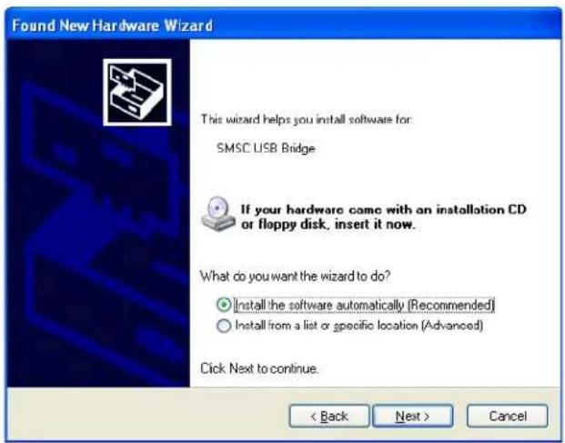
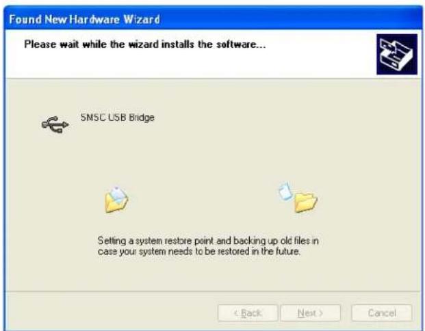
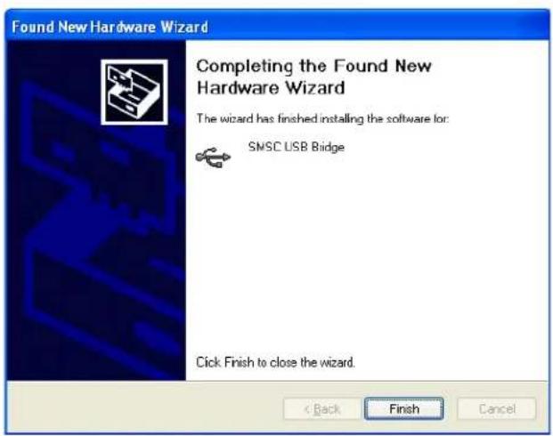
To complete the installation, connect the USB mini connector to the EVB and the standard USB connector to any available USB port on the PC. If the USB Bridge driver has not previously been installed on the selected USB port, the "Find New Hardware" wizard will pop up on the PC's screen. Follow the on-screen instructions to complete the installation process. See Figure 2.5 through Figure 2.8 for a step by step view of the installation.
Once installation of the USB Bridge is complete, the GUI software will begin communications with the device on the EVB.

text_image
Found New Hardware Wizard Welcome to the Found New Hardware Wizard Windows will search for current and updated software by looking on your computer, on the hardware installation CD, or on the Windows Update Web site (with your permission). Read our privacy policy Can Windows connect to Windows Update to search for software? Yes, this time only Yes, now and every time I connect a device No, not this time Click Next to continue. < Back Next > CancelFigure 2.5 USB Bridge Driver Installation Step 1
text_image
Found New Hardware Wizard This wizard helps you install software for SMSC USB Bridge If your hardware came with an installation CD or floppy disk, insert it now. What do you want the wizard to do? • Install the software automatically (Recommended) • Install from a list or specific location (Advanced) Click Next to continue. < Back Next > CancelFigure 2.6 USB Bridge Driver Installation Step 2
text_image
Found New Hardware Wizard Please wait while the wizard installs the software... SMSC USB Bridge Setting a system restore point and backing up old files in case your system needs to be restored in the future. < Back Next > CancelFigure 2.7 USB Bridge Driver Installation Step 3
text_image
Found New Hardware Wizard Completing the Found New Hardware Wizard The wizard has finished installing the software for: SMSC USB Bridge Click Finish to close the wizard. < Back Finish CancelFigure 2.8 USB Bridge Driver Installation Step 4
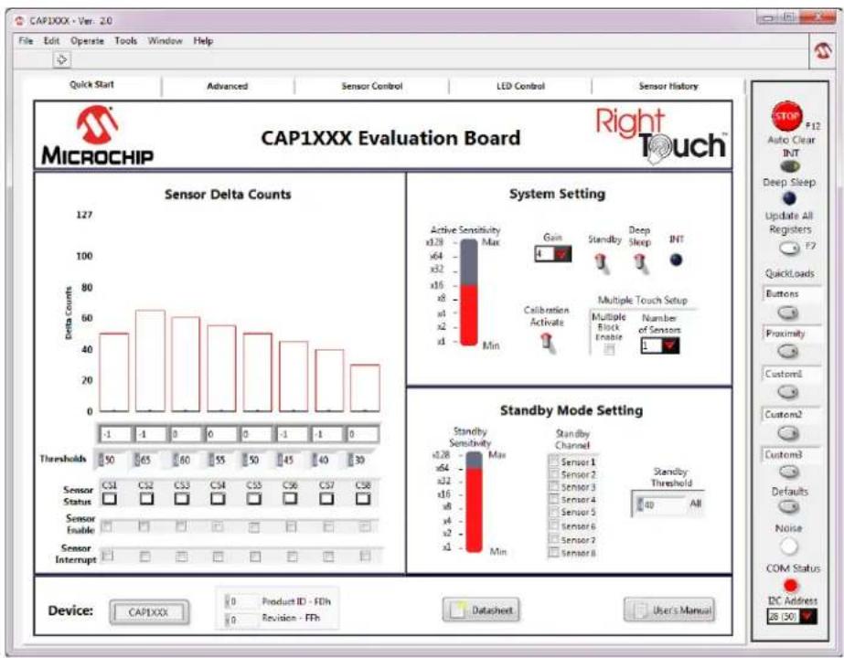
3 Quick Start Window
The Quick Start Window provides the same information as the Advanced Window, but reduces the number of options for a more manageable initial user experience. For more information on what options are provided on the Quick Start Window and how to use them, refer to the CAP1xxx Quick Start Guide provided with the CAP1xxx CD.
4 Advanced Tab
4.1 Default Conditions
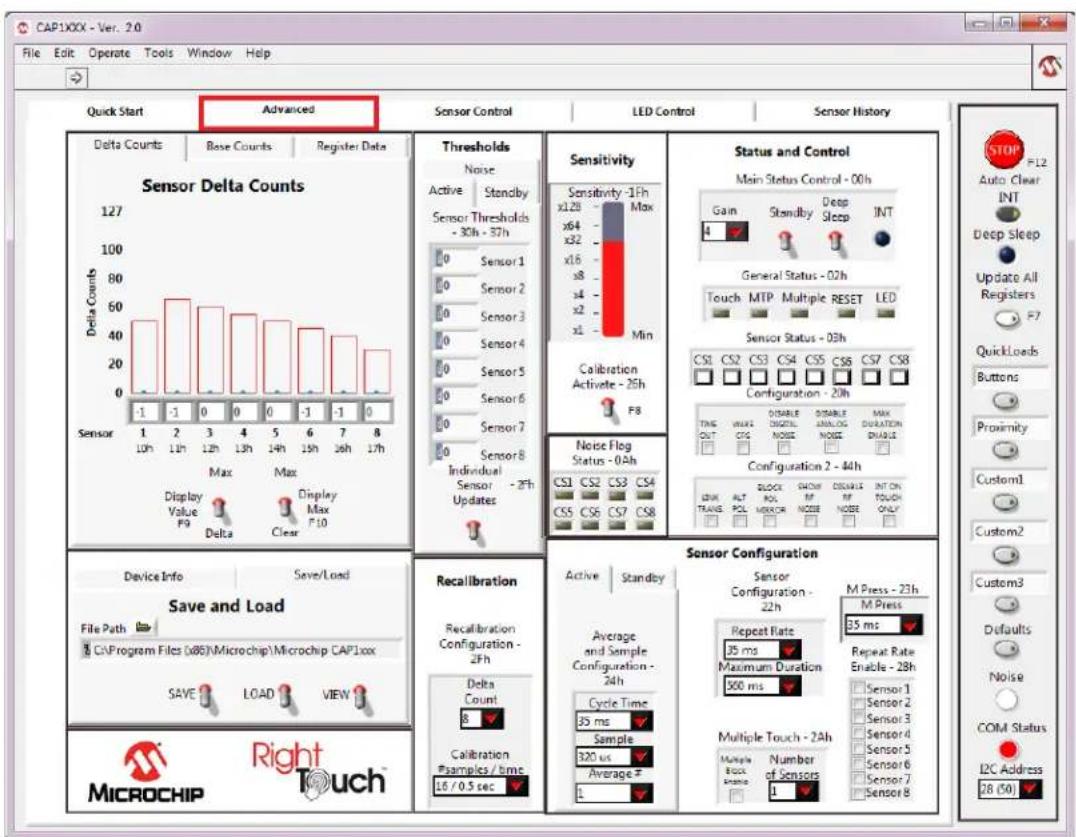
Communications begin as soon as the CAP1xxx GUI software detects the presence of the CAP1xxx evaluation board. The GUI then reconfigures the CAP1xxx evaluation board with predetermined values specific to the evaluation board's hardware. Figure 4.1 shows the default GUI for the CAP1188 evaluation board.
text_image
CAP1XXX - Ver. 2.0 File Edit Operate Tools Window Help Quick Start Advanced Sensor Control LED Control Sensor History Delta Counts Base Counts Register Data Sensor Delta Counts 127 100 80 60 40 20 0 -1 -1 -1 Sensor 1 2 3 4 5 6 7 8 10h 12h 13h 14h 15h 16h 17h Max Max Display Value F9 Delta Display Max F10 Thresholds Noise Active Standby Sensor Thresholds - 30h - 37h 0 Sensor 1 0 Sensor 2 0 Sensor 3 0 Sensor 4 0 Sensor 5 0 Sensor 6 0 Sensor 7 0 Sensor 8 Individual Sensor - 27h Updates Sensitivity -1ph Max x128 x64 x32 x16 x8 x4 x2 x1 Min Calibration Activate - 25h F8 Noise Flog Status - 04h CS1 CS2 CS3 CS4 CS5 CS6 CS7 CS8 DISENT OUTF OUT CTG COLD NOISE INSULG NOISE INSULG INSULG INSULG INSULG INSULG INSULG INSULG INSULG INSULG INSULG INSULG INSULG INSULG INSULG INSULG INSULG INSULG INSULG INSULG INSULG INSULG INSULG INSULG INSULG INSULG INSULG INSULG INSULG INSULG INSULG INSULG INSULG INSULG INSULG IN Status and Control Main Status Control - 00h Gain Standby Deep Sleep INT General Status - 02h Touch MTP Multiple RESET LED Sensor Status - 03h CS1 CS2 CS3 CS4 CS5 CS6 CS7 CS8 Configuration - 20h TING OUT DISABLE CONTINUING NOISE INSULG NOISE INSULG INSULG INSULG INSULG INSULG INSULG INSULG INSULG INSULG INSULG INSULG INSULG INSULG INSULG INSULG INSULG INSULG INSULG INSULG INSULG INSULG INSULG INSULG INSULG INSULG INSULG INSULG INSULG INSULG INSULG INSULC BLOCK SMOV DISCHES INT ON TOUCH ONLY LOCK PDL NOBER NOT NODE ONLY Sensor Configuration Active Standby Sensor Configuration - 22h Average and Sample Configuration - 24h Repeat Rate 35 ms Maximum Duration 500 ms Repeat Rate Enable - 28h M Press - 23h 35 ms Repeat Rate Enable - 28h Sensor 1 Sensor 2 Sensor 3 Sensor 4 Sensor 5 Sensor 6 Sensor 7 Sensor 8 Multiple Touch - 2Ah Multiple Lock Range Number of Sensors 1 LDC Address 28 (50) Device Info Save/Load Save and Load File Path C:\Program Files\08\Microchip\Microchip CAP1xxx SAVE LOAD VIEW MICROCHIP Right TouchFigure 4.1 Default State of RightTouch GUI with the CAP1188 Evaluation Board
4.2 Tips for Using the RightTouch Evaluation System
- For many items on the GUI control panels, the register address is listed after the control name.
■ After communications are established between the GUI and the evaluation board, the GUI will reconfigure the device. Users can save setting configurations to user-named files which can be reloaded at any time for quick re-configuration (see Section 4.4, "Save/Load Tab").
■ QuickLoad options are provided on the right to quickly change the evaluation board's behavior between 'Buttons', 'Proximity', and 'Metal over Capacitive'.
4.2.1 Numbering Systems Views
Some control panels allow values to be displayed using different numbering systems: Decimal, Hex, Octal, Binary or SI Notation.
To view a value using a different numbering system, click the indicator to the left of the value in the cell, shown circled in Figure 4.2.

Figure 4.2 Numbering System Indicators
4.2.2 Keyboard Shortcuts
Some GUI controls have keyboard shortcuts, as shown in Table 4.1.
Table 4.1 CAP1188 Family EVB GUI Keyboard Shortcuts
| GUI CONTROL SHORTCUT CONTROL DESCRIPTION | ||
| Run CTRL + R Section 4.5.1, "Stop and Run Buttons" | ||
| Load Buttons file F1 Section 4.5.5, "QuickLoad Buttons" | ||
| Load Proximity file F2 Section 4.5.5, "QuickLoad Buttons" | ||
| Load MOC file F3 Section 4.5.5, "QuickLoad Buttons" | ||
| Load Custom1 file | F4 | Section 4.5.5, "QuickLoad Buttons" |
| Load Custom2 file | F5 | Section 4.5.5, "QuickLoad Buttons" |
| Load Defaults | F6 | Section 4.5.6, "Defaults Button" |
| Update All Registers | F7 | Section 4.5.4, "Update All Registers" |
| Calibration Activate All | F8 | Section 4.9, "Sensitivity Control Panel" |
| Stop | F12 | Section 4.5.1, "Stop and Run Buttons" |
4.3 Device Information and Datasheet Link
In addition to the device name lighting up on the evaluation board and displaying in the software title bar, the Device Information Control Panel also shows the device that has been populated on the
evaluation board. Figure 4.3 shows the Device Information Control Panel for the CAP1188 evaluation board.. This control panel also shows the values from reading the Product ID Register (FDh) and Revision Register (FFh) on the device.

text_image
CAP1XXX - Ver. 2.0 File Edit Operate Tools Window Help Quick Start Advanced Sensor Control LED Control Sensor History Delta Counts Base Counts Register Date Sensor Delta Counts 127 100 80 60 40 20 0 -1 -1 -1 -1 -1 -1 -1 -1 -1 -1 -1 -1 -1 -1 -1 -1 -1 -1 -1 -1 -1 -1 -1 -1 -1 -1 -1 -1 -1 -1 -1 -1 -1 -10 Display Value PS Delta Max Display Max F10 Thresholds Noise Active Standby Sensor Thresholds - 30h - 37h Sensor 1 Sensor 2 Sensor 3 Sensor 4 Sensor 5 Sensor 6 Sensor 7 Sensor 8 Individual Sensor - 2Fh Updates Sensitivity Sensitivity - 1Fh Max xL28 x64 xL2 xL6 x8 x4 x2 x1 Min Calibration Activate - 26h FB Noise Flag Status - 0Ah CS1 CS2 CS3 CS4 CS5 CS6 CS7 CS8 CS9 S00 S01 S02 S03 S04 S05 S06 S07 S08 S09 S10 S11 S12 S13 S14 S15 S16 S17 S18 S19 S20 S21 S22 S23 S24 S25 S26 S27 S28 S29 S30 S31 S32 S33 S34 S35 S36 S37 S38 S39 S40 S41 S42 S43 S44 S45 S46 S47 S48 S49 S50 S51 S52 S53 S54 S55 S56 S57 S58 S59 S60 S61 S62 S63 S64 S65 S66 S67 S68 S69 S70 S71 S72 S73 S74 S75 S76 S77 S78 S79 S80 S81 S82 S83 S84 S85 S86 S87 S88 S89 S90 S91 S92 S93 S94 S95 S96 S97 S98 S99 S100 Device Info Save/Load Device Information Device Name Product ID FDh Datasheet CAP1XXX Revision - FFh User's Manual MicroCHIP Right Touch Recalibration Recalibration Configuration - 2Fh Delta Count Calibration #samples / time 16 / 0.5 sec Sensor Configuration Sensor Configuration - 22h M Press - 23h Repeat Rate 35 ms Repeat Rate Enable - 28h Maximum Duration 560 ms Repeat Rate 33 ms Maximum Duration 560 ms Repeat Rate Enable - 28h Multiple Touch - 2Ah Number of Sensors 1 M Press 35 ms 33 ms 33 ms 33 ms 33 ms 33 ms 33 ms 33 ms 33 ms 33 ms 33 ms 33 ms 33 ms 33 ms 33 ms 33 ms 33 ms 33 ms 33 ms 33 ms 33 ms 33 ms 33 ms 33 ms 33 ms 33 ms 3Figure 4.3 Device Information Control Panel
Clicking the Datasheet button opens a browser window that will display a PDF file of the datasheet of the connected device.
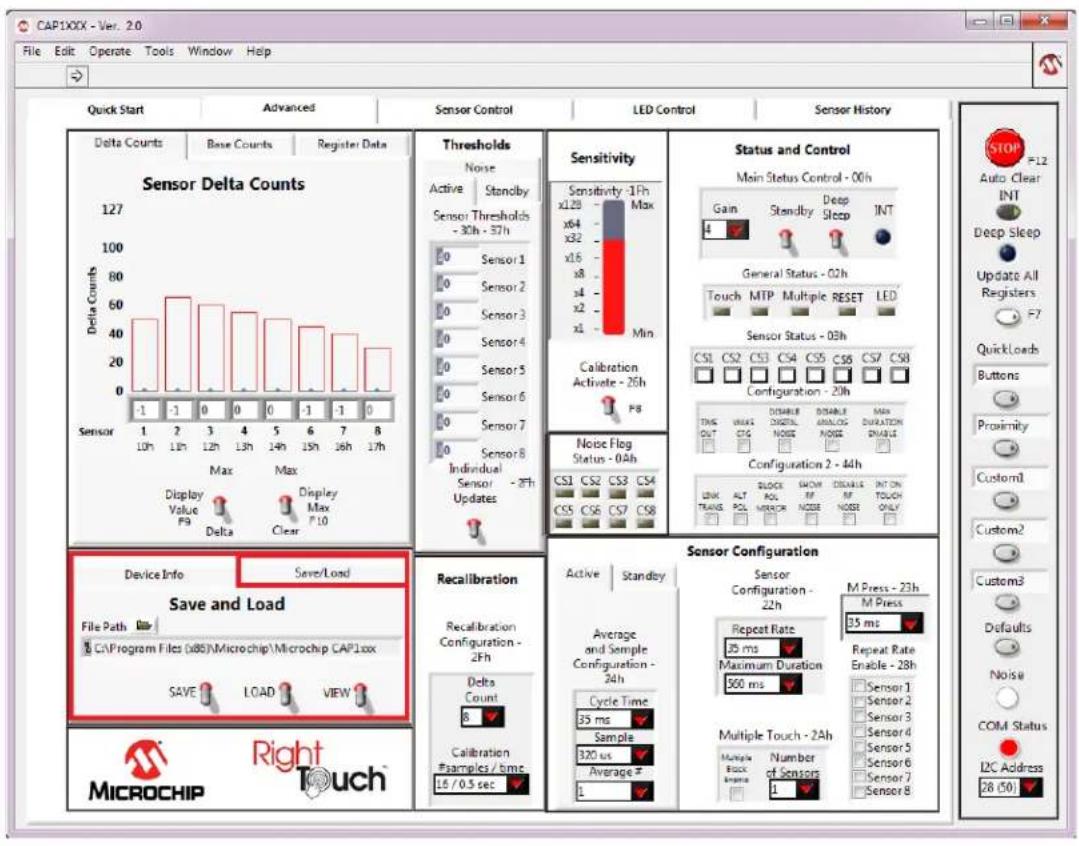
4.4 Save/Load Tab
The Save/Load tab, located in the lower left corner of the Advanced Tab and shown in Figure 4.4, allows the user to save all the settings that have been configured for the device to allow quick reconfiguration at any time.
text_image
CAP1XXX - Ver. 2.0 File Edit Operate Tools Window Help Quick Start Advanced Sensor Control LED Control Sensor History Delta Counts Base Counts Register Data Sensor Delta Counts 127 100 80 60 40 20 0 -1 -1 Sensor 1 10h 12h 13h 14h 15h 16h 17h Max Max Display Value P9 Delta Clear Thresholds Noise Active Standby Sensor Thresholds - 30h - 37h Sensor 1 Sensor 2 Sensor 3 Sensor 4 Sensor 5 Sensor 6 Sensor 7 Sensor 8 Individual Sensor - 28h Updates Sensitivity Sensitivity -1ph Max x128 x64 x32 x16 x8 x4 x2 x1 Min Calibration Active - 26h PS Noise Flog Status - 0.4h CS1 CS2 CS3 CS4 CS5 CS6 CS7 CS8 DISELLA ANALOG MAX DUSSELANOS INJAMULIN Configuration - 20h INS OUT CTG NOISE NOISE DIMRK Configuration 2 - 44h LOCK ALT POL NISER INT ON TOUCH ONLY Device Info Save/Load Save and Load File Path C:\Program Files (x86)\Microchip\Microchip CAP1xxx SAVE LOAD VIEW Recalibration Recalibration Configuration - 2Fh Delta Count 8 Calibration Psamples / time: 16 / 0.5 sec Sensor Configuration Sensor Configuration - 22h M Press - 23h M Press - 35 ms Average and Sample Configuration - 24h Repeat Rate 25 ms Maximum Duration 500 ms Repeat Rate Enable - 28h Sensor 1 Sensor 2 Sensor 3 Sensor 4 Sensor 5 Sensor 6 Sensor 7 Sensor 8 Multiple Touch - 2Ah Number of Sensors L1 Temperature Control - 00h Main Status Control - 00h Gain Standby Deep Sleep INT General Status - 02h Touch MTP Multiple RESET LED Sensor Status - 03h CS1 CS2 CS3 CS4 CS5 CS6 CS7 CS8 Configuration - 20h THIS OUT CTG NOISE NOISE DIMRK ALT POL NISER INT ON TOUCH ONLY BLOCK SNOW DISCRAS INT ON TOUCH ONLY STOP FILE AUTO CLEAR INT Deep Sleep Update All Registers F7 Quick Loads Buttons Proximity Customl Custom2 Custom3 Custom3 Defaults Noise COM Status L2C Address 28 (50) MICROCHIP Right TouchFigure 4.4 Save/Load Tab
To save device configuration settings:
■ Using the GUI, configure the CAP1xxx as desired.
■ Select the Save/Load tab.
■ Type in a path, or click the folder icon to browse to your desired save location.
- Click the 'SAVE' switch to store the configuration.
Notes:
- The file should be named with the extension '.txt' or similar plain-text file format. The data is saved in two columns separated by tabs. The first column is the register's address, and the second column is the register's value.
- If a file with the same name already exists, the file will be overwritten and old data will be lost.
- When a file is loaded, the Auto Clear INT button is disabled. Click it to re-enable auto-clearing of interrupts (see Section 4.5.2, "Auto Clear INT").
Once a file is saved, it can be recalled at any time by selecting the file in the data path window and clicking the "LOAD" switch. The file can also be linked to a QuickLoad button (see Section 4.5.5, "QuickLoad Buttons").
The evaluation board GUI comes with several sample configuration files which vary the settings for different functions.
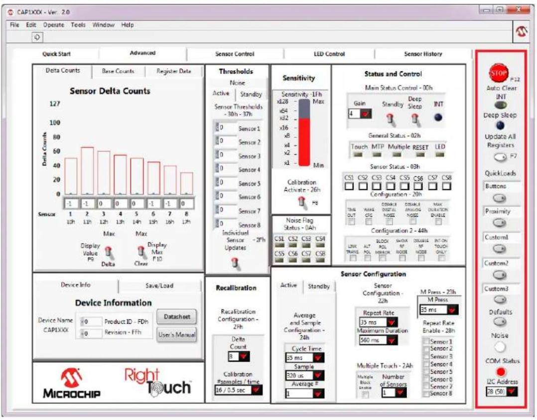
4.5 Communications Status and Control Panel
Along the right side of the GUI is the control panel shown in Figure 4.5. This is the Communications Status and Control Panel, which controls and displays the status of the communications between the GUI software and the evaluation board and includes buttons for loading configurations. This control panel is always displayed.
text_image
CAP1XXX - Ver. 2.0 File Edit Operate Tools Window Help Quick Start Advanced Sensor Control LED Control Sensor History Delta Counts Base Counts Register Data Sensor Delta Counts 127 100 80 60 40 20 0 -1 -1 -1 -1 -1 -1 -1 -1 -1 -1 -1 -1 -1 -1 -1 -1 -1 -1 -1 -1 -1 -1 -1 -1 -1 -1 -1 -1 -1 -1 -1 -1 -1 -10 Max Max Display Value PS Delta Clear Thresholds Noise Active Standby Sensor Thresholds - 30h - 37h 0 Sensor 1 0 Sensor 2 0 Sensor 3 0 Sensor 4 0 Sensor 5 0 Sensor 6 0 Sensor 7 0 Sensor 8 Individual Sensor - 2Fh Updates Sensitivity - 1Fh Max xL28 - xL2 - xL2 - xL2 - xL2 - xL2 - xL2 - xL2 - xL2 - xL2 - xL2 - xL2 - xL2 - xL2 - xL2 - xL2 - xL2 - xL2 - xL2 - xL2 - xL2 - xL2 - xL2 - xL2 - xL2 - xL2 - xLb Gain Standby Deep Sleep INT General Status - 02h Touch MTP Multiple RESET LED Sensor Status - 03h CS1 CS2 CS3 CS4 CS5 CS6 CS7 CS8 Configuration - 20h TAG NAME DISABLE DIMENSION MAX OUT CTG NOISE DURATION ENABLE Configuration 2 - 44h LINK ALT SLOK SHOWN INSURANCE INT ON TOUCH ONLY TRANS POL PROACH BLOOD INSURANCE INSURANCE INSURANCE INSURANCE INSURANCE INSURANCE INSURANCE INSURANCE INSURANCE INSURANCE INSURANCE INSURANCE INSURANCE INSURANCE INSURANCE INSURANCE INSURANCE INSURANCE INSURANCE INSURANCE INSURANCE INSURANCE INSURANCE INSURANCE INSURANCE INSURANCE INSURANCE INSURANCE INSURANCE INSURANCE INSURANCE INSURANCE INSURANCE INSURANCE IN Device Info Save/Load Device Information Device Name CAPIXXX Product ID FDh Revisn - FFh Datasheet User's Manual Recalibration Recalibration Configuration - 2Fh Delta Count 8 Calibration #samples / time 16 / 0.5 sec Sensor Configuration Sensor Configuration - 22h Average and Sample Configuration - 24h Cycle Time 35 ms Sample 320 us Average F M Press - 23h M Press 35 ms Repeat Rate Enable - 28h Sensor 1 Sensor 2 Sensor 3 Sensor 4 Sensor 5 Sensor 6 Sensor 7 Sensor 8 Multiple Touch - 2Ah Number of Sensors 1 MicroCHIP Right Touch™Figure 4.5 Communications Status and Control Panel
4.5.1 Stop and Run Buttons
The STOP button, on the Panel shown in Figure 4.5, halts GUI software communication with the evaluation board. When this button is clicked, the Run button, which has an arrow on it, displays below the menu bar, as shown in Figure 4.6.
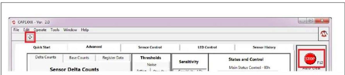
text_image
CAP1XXX - Var. 2.0 File Edit Operate Tools Window Help Quick Start Advanced Sensor Control LED Control Sensor History Delta Counts Base Counts Register Data Thresholds Sensitivity Status and Control Sensor Delta Counts Noise Main Status Control - 00h Auto Clear SensitivityFigure 4.6 Run Button
To restart communications between the software and the evaluation board, click the Run button. The arrow button disappears when communications resume.
To close the program, use the red X in the upper right corner of the window.
4.5.2 Auto Clear INT
When the Auto Clear INT button is enabled (dark gray), the INT bit, ALERT pin, and status indicators are continuously cleared. When the Auto Clear INT button is disabled (light gray), the user must manually clear interrupts by clicking the INT indicator on the Status and Control Panel or the Auto Clear INT button. This is shown in Figure 4.5 at the top of the red highlighted box.
4.5.3 Deep Sleep Indicator
The Deep Sleep indicator located below the Auto Clear INT toggle switch in the upper right and shown in Figure 4.5, indicates whether the device is in the Deep Sleep state. During normal operation, this indicator is dark. When the device is placed into the Deep Sleep state, this indicator turns blue (or a lighter color, depending on the PC settings).
4.5.4 Update All Registers
The Update All Registers button shown in Figure 4.5, will update all values displayed on the GUI control panels to reflect the current device registers. In order to keep control panel response time reasonable, only a few of the device registers are read and continuously updated during normal operation. Clicking the Update All Registers button will automatically cycle refreshing all controls and readings on the control panel.
The keyboard shortcut is F7.
4.5.5 QuickLoad Buttons
The QuickLoad buttons, on the Panel shown in Figure 4.5, allow the user to quickly load configuration files (see Section 4.4, "Save/Load Tab").
There are five QuickLoad buttons available. Each button is linked to a ".txt" file in your installation directory that has the filename listed above the button. To link the button to a different file, type the filename (without the extension) in the box above the button, then click off the field. Figure 4.7 shows new names for the first two buttons. To load the file, click the button or press the shortcut key listed next to the button.
The 'Buttons' QuickLoad option will set up the CAP1xxx evaluation board for each sensor to behave as normal touch buttons. Due to the thin front cover of the evaluation boards, this means the gain is set to the lowest option, and the sensitivity option is greatly reduced from the maximum.
The 'Proximity' QuickLoad option will set up the CAP1xxx evaluation board for all of the sensors to detect the proximity of a hand approaching. The gain and sensitivity, in this case, are set very high. Using this configuration, you can see how the size of the sensors will affect the possible range of proximity detection.

text_image
QuickLoads Buttons Proximity Custom1 Custom2 Custom3Figure 4.7 QuickLoad Buttons
4.5.6 Defaults Button
The Defaults button, toward the bottom of the red highlighted panel shown in Figure 4.5, loads the default register settings on the device as described in the datasheet.
The keyboard shortcut is F6.
4.5.7 COM Indicator
The COM indicator, toward the bottom of the Panel shown in Figure 4.5, indicates the status of communications over the I2C. During normal operation, the COM indicator is dark. If I2C communications fail, the COM indicator turns red.
4.5.8 I2C Address
I2C Address, at the bottom of the red highlighted panel shown in Figure 4.5, indicates the 2C address of the device.
4.6 Delta Counts Tab
The Delta Counts tab on the Main window and in the Quick Start window shown in Figure 4.8, displays the delta counts of the capacitive sensor channels. The Delta Count Register address for each sensor input is listed below the sensor number.

text_image
CAP1XXX - Ver. 2.0 File Edit Operate Tools Window Help Quick Start Advanced Sensor Control LED Control Sensor History Delta Counts Base Counts Register Data Sensor Delta Counts 127 100 80 60 40 20 0 -1 -1 -1 -1 -1 -1 -1 -1 -1 -1 -1 -1 -1 -1 -1 -1 -1 -1 -1 -1 -1 -1 -1 -1 -1 -1 -1 -1 -1 -1 -1 -1 -1 -10 Sensor Display Value FB Delta Max Display Max F10 Clear Thresholds Noise Active Standby Sensor Thresholds - 30h - 37h 0 Sensor 1 0 Sensor 2 0 Sensor 3 0 Sensor 4 0 Sensor 5 0 Sensor 6 0 Sensor 7 0 Sensor 8 Individual Sensor - 2fh Updates Sensitivity Sensitivity - 1fh xL28 Max xE4 xE2 xX6 xX2 xX6 xX4 xX2 xX6 Min Calibration Activate - 26h FB Noise Flag Status - 0Ah CS1 CS2 CS3 CS4 CS5 CS6 CS7 CS8 OSIBLE OSIBLE OSIBLE OSIBLE OSIBLE OSIBLE OSIBLE OSIBLE OSIBLE OSIBLE OSIBLE OSIBLE OSIBLE OSIBLE OSIBLE OSIBLE OSIBLE OSIBLE OSIBLE OSIBLE OSIBLE OSIBLE OSIBLE OSIBLE OSIBLE OSIBLE OSIBLE OSIBLE OSIBLE OSIBLE OSIBLE OSIBLE OSIBLE OSIBLE OSIBLE OSIBLE OSIBLE OSIBLE OSIBLE OSIBLE OSIBLE OSIBLE OSIBLE OSIBLE OSIBLE OSIBLE OSIBLE OSIBLE OSIBLE OSIBLE OSABLE OSIBLE OSIBLE OSIBLE OSIBLE OSIBLE OSIBLE OSIBLE OSIBLE OSIBLE OSIBLE OSIBLE OSIBLE OSIBLE OSIBLE OSIBLE OSIBLE OSIBLE OSIBLE OSIBLE OSIBLE OSIBLE OSIBLE OSIBLE OSIBLE OSIBLE OSIBLE OSIBLE OSIBLE OSIBLE OSIBLE OSIBLE OSIBLE OSIBLE OSIBLE OSIBLE OSIBLE OSIBLE OSIBLE OSIBLE OSIBLE OSIBLE OSIBLE OSIBLE OSIBLE OSIBLE OSIBLE OSIBLE OSIBLE OSIBLE OSBILEOSIDEOSIDEOSIDEOSIDEOSIDEOSIDEOSIDEOSIDEOSIDEOSIDEOSIDEOSIDEOSIDEOSIDEOSIDEOSIDEOSIDEOSIDEOSIDEOSIDEOSIDEOSIDEOSIDEOSIDEOSIDEOSIDEOSIDEOSIDEOSIDEOSIDEOSIDEOSIDEOSIDEOSIDEOSIDEOSIDEOSIDEOSIDEOSIDEOSIDEOSIDEOSIDEOSIDEOSIDEOSIDEOSIDEOSIDEOSIDEOSIDEOSIDEOSILEOSIDEOSILEOSIDEOSILEOSIDEOSILEOSIDEOSILEOSIDEOSILEOSIDEOSILEOSIDEOSILEOSIDEOSILEOSIDEOSILEOSIDEOSILEOSIDEOSILEOSIDEOSILEOSIDEOSILEOSIDEOSILEOSIDEOSILEOISOELOLETSOLOESOLOESOLOESOLOESOLOESOLOESOLOESOLOESOLOESOLOESOLOESOLOESOLOESOLOESOLOESOLOESOLOESOLOESOLOESOLOESOLOESOLOESOLOESOLOESOLOESOLOESOLOESOLOESOLOESOLOESOLOESOLOESOLOESOLOESSOPROCCDCDCDCDCDCDCDCDCDCDCDCDCDCDCDCDCDCDCDCDCDCDCDCDCDCDCDCDCDCDCDCDCDCDCDCDCDCDCDCDCDCDCDCDCDCDCDCDCDCDCDCDCDCDCDCDCDCDCDCDCDCDCDCDCDCDCDCDCDCDCDCDCDCDCDCDCDCDCDCDCDCDCDCDCDCDCDCDCDCDCDCDCDCDCDCDCDCDCDCDCDCCDDCCDDCCDDCCDDCCDDCCDDCCDDCCDDCCDDCCDDCCDDCCDDCCDDCCDDCCDDCCDDCCDDCCDDCCDDCCDDCCDDCCDDCCDDCCDDCCDDCCDDCCDDCCDDCCDDCCDDCCDDCCDDCCDDCCDDCCDDCCDDCCDDCCDDCCDDCCDDCCDDCCDDCCDDCCDDCCDDCCDDCCDDCCDDCCDDCCDDCCDCCDDCCDDCCDDCCDDCCDDCCDDCCDDCCDDCCDDCCDDCCDDCCDDCCDDCCDDCCDDCCDDCCDDCCDDCCDDCCDDCCDDCCDDCCDDCCDDCCDDCCDDCCDDCCDDCCDDCCDDCCDDCCDDCCDDCCDDCCDDCCDDCCDDCCDDCCDDCCDDCCDDCCDDCCDDCCDDCCDDCCDDCCDDCCDDCCDDCCTCCTCCTCCTCCTCCTCCTCCTCCTCCTCCTCCTCCTCCTCCTCCTCCTCCTCCTCCTCCTCCTCCTCCTCCTCCTCCTCCTCCTCCTCCTCCTCCTCCTCCTCCTCCTCCTCCTCCTCCTCCTCCTCCTCCTCCTCCTCCTCCTCCTCCHOCOCOCOCOCOCOCOCOCOCOCOCOCOCOCOCOCOCOCOCOCOCOCOCOCOCOCOCOCOCOCOCOCOCOCOCOCOCOCOCOCOCOCOCOCOCOCOCOCOCOCOCOCOCOCOCOCOCOCOCOCOCOCOCOCOCOCOCOCOCOCOCOCOCOCOCOCOCOCOCOCOCOCOCOCOCOCOCOCOCOCOCOCOCOCOCOCOCOCOCUCCHICR Touch™ MICROCHIP Right Touch™Figure 4.8 Delta Counts Tab
When the Display Value switch is set to Delta, the number cell below each indicator bar displays the least significant byte of that channel's current delta count. When the Display Value switch is set to Max,
the number cell below each indicator bar displays the max delta count for the channel (when the Max Enable switch is up). The outline on the top of each indicator bar shows the threshold of the sensor channel. As a sensor pad is being approached and touched, a black bar displays the actual delta count.
The Max Enable switch, when set in the upper position, turns on display of thin blue bars that indicate the maximum delta count for each channel. These bars display the maximum delta count until the Max Enable switch is set to the lower, "Clear" position.
Settings that control the threshold values are covered in Section 4.9, "Sensitivity Control Panel".
All numbers (except register addresses) on this tab are displayed in decimal format.
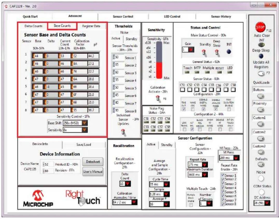
4.7 Base Counts Tab
The Base Counts tab on the Main window, shown in Figure 4.9, displays Base, Delta, Current Count, Calibration Factor, and Capacitance in a register format and includes a Sensitivity control. This tab can be used to check the sensors' calibration values.
text_image
CAP1128 - Ver. 2.0 Quick Start Advanced Sensor Control LED Control Sensor History Delta Counts Base Counts Register Data Sensor Base and Delta Counts Sensor Base Delta Current Calibration Sensor 50h-57h 10h-17h 81h-88h pF 1 44 9 53 E2 44.3 2 46 0 46 8A 27.1 3 46 0 46 74 22.7 4 47 0 47 6A 20.8 5 46 -1 45 6B 20.4 6 47 0 47 GF 21.8 7 47 0 47 6B 21.0 8 47 0 47 55 16.7 Sensitivity Control - 1Fh Base Shift 256x (MSB) Sensitivity 8x Thresholds Noise Active Standby Sensor Thresholds - 30h - 37h 50 Sensor 1 65 Sensor 2 60 Sensor 3 55 Sensor 4 50 Sensor 5 45 Sensor 6 40 Sensor 7 30 Sensor 8 Individual Sensor - 2Fh Updates Sensitivity -1Fh Max x64 x32 x16 x8 x6 x2 x1 Min Calibration Activate - 26h FB Noise Flag Status - 0Ah CS1 CS2 CS3 CS4 CS5 CS6 CS7 CS8 CS5 CS6 CS7 CS8 Status and Control Main Status Control - 00h Gain Standby Deep Sleep INT General Status - 02h Touch MTP Multiple RESET LED Sensor Status - 03h True OUT CANC DISABLE ANALOG MAX SUSTOS SETTLE Configuration - 20h Configuration 2 - 44h LINK AL TAGO SHOWN ON TOUCH ONLY Device Info Save/Load Device Information Device Name Product ID FDIn Datasheet CAP1128 Revision FFh User's Manual Recalibration Recalibration Configuration - 2Fh Delta Count 16 Calibration #samples / time 64 / 2 sec Sensor Configuration Sensor Configuration - 22h M Press - 23h Repeat Rate 175 ms Maximum Duration Maximum Duration 5600 ms Repeat Rate Enable - 28h Multiple Touch - 2Ah Multiple Pack Inage Number of Sensors 1 STOP F12 Auto Clear INT Deep Sleep Update All Registers F7 QuickLoads Buttons Proximity Customl Custom2 Custom3 Defaults Noise COM Status I2C Address 28 (%)Figure 4.9 Base Counts Tab
The formats of values on this control panel can be changed to Hexadecimal, Octal, Binary or SI Notation by clicking the tap in the front of each data cell (see Section 4.2.1, "Numbering Systems Views").
The Sensitivity Control section affects the Sensitivity Control Register (1Fh). The Base Shift controls the scaling and data presentation of the Base Count registers. The higher the value of these bits, the larger the range and the lower the resolution of the data presented. It should not be necessary to modify this number.
The Sensitivity drop-down list allows update of the sensitivity multiplier, which controls sensitivity of a touch detection. This value can also be updated using the Sensitivity bar in the Sensitivity Control Panel (see Figure 4.11, "Sensitivity Control Panel").
4.8 Register Data Tab
The Register Data tab in the Advanced window shown in Figure 4.10, displays a list of all registers and allows the user to directly write to any register of the device.

text_image
CAP1128 - Ver. 20 Quick Start Advanced Sensor Control LED Control Sensor History Delta Counts Base Counts Register Date Raw Data - All Registers All Raw Device Registers 17 11 0 12 0 13 0 14 0 15 0 16 FF 17 0 18 0 19 0 Single Byte Register Access Address 0 Data Write Single Byte Thresholds Noise Active Standby Sensor Thresholds - 30h - 37h 50 Sensor 1 65 Sensor 2 60 Sensor 3 55 Sensor 4 50 Sensor 5 45 Sensor 6 40 Sensor 7 30 Sensor 8 Individual Sensor - 2Fh Updates Sensitivity Sensitivity - 1Fh Max x128 x64 x32 x16 x8 x4 x2 x1 Min Calibration Activate - 26h FB Noise Flag Status - 0Ah CS1 CS2 CS3 CS4 CS5 CS6 CS7 CS8 Configuration - 20h TRE OUT CSG DISABLE ANALOG NOISE DISABLE MAX DURATION ONLINE Configuration 2 - 4H LINK ALT BLOO SHOWN INT NOISE DISABLE INT ON TOUCH ONLY Device Info Save/Load Device Information Device Name 52 Product ID - PDh Datasheet CAP1128 80 Revision - FFh User's Manual Recalibration Recalibration Configuration - 2Fh Delta Count 16 Calibration #Samples / time 64 / 2 sec Sensor Configuration Sensor Configuration - 22h M Press - 23h Repeat Rate 175 ms Maximum Duration 5600 ms Repeat Rate Enable - 28h √Sensor 1 √Sensor 2 √Sensor 3 √Sensor 4 √Sensor 5 √Sensor 6 √Sensor 7 √Sensor 8 √MPC Touch - 2Ah Number of Sensors L √Number of Sensors L √MPC Touch - 2Ah Number of Sensors L √MPC Touch - 2Ah Number of Sensors L √MPC Touch - 2Ah Number of Sensors L √MPC Touch - 2Ah Number of Sensors L √MPC Touch - 2Ah Number of Sensors L √MPC Touch - 2Ah Number of Sensors L √MPC Touch - 2Ah Number of Sensors L √MPC Touch - 2Ah Number of Sensors L √MPC Touch = 2Ah (50) Device Information User's Manual MICROCHIP Right TouchFigure 4.10 Raw Data Tab
The All Raw Device Registers display shows a scrollable list of registers and their current values. It is important to note that not all addresses are physical memory locations on the device; these registers will read "0". Likewise, some registers shown that are undocumented in the datasheet may have data.
Editing these registers can cause unexpected results. If a mistake is made while making a manual edit in this window, it may be necessary to revert to the defaults or a stored configuration.
The Single Byte Register Access control allows direct write to any register within the device.
The formats of address and data on this control panel are hexadecimal by default, with the option to change to Decimal, Octal, Binary or SI Notation (see Section 4.2.1, "Numbering Systems Views").
4.9 Sensitivity Control Panel
The Sensitivity Control Panel provides controls for capacitive sensor input sensitivity and on-demand calibration, as shown in Figure 4.11.
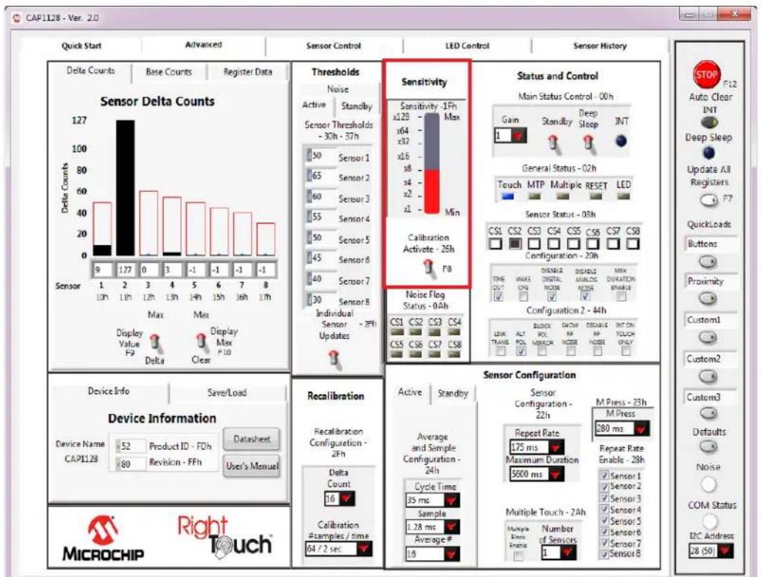
Figure 4.11 Sensitivity Control Panel
The Sensitivity bar affects the Sensitivity Control Register (1Fh), which controls the amount of capacitance change required to affect the sensor's signal.. Clicking the bar changes the setting. The value selected is also reflected in the Sensitivity cell on the Base Counts Tab.
Occasionally it is desirable to force recalibration of the sensor inputs. Clicking the Calibration Activate switch will recalibrate the sensor inputs.
Note: This is equivalent to writing 0xFF to the Calibration Activate register (26h).
4.10 Thresholds Control Panel
The Thresholds Control Panel, shown in Figure 4.12, contains 4 tabs which are described below.
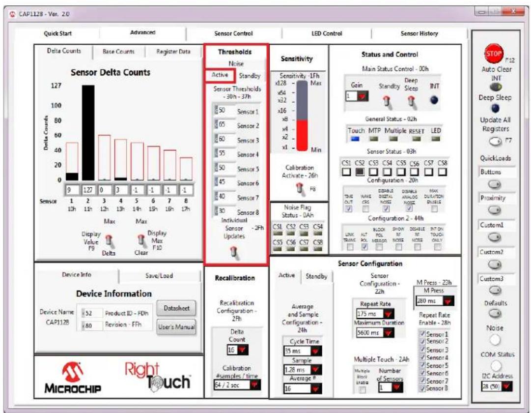
Figure 4.12 Thresholds Control Panel - Active Tab Displayed
4.10.1 Active Tab
The Active tab of the Advanced window's Thresholds section, shown in Figure 4.12, contains the sensor input thresholds (registers 30h - 37h) that define the delta count level at which touches are reported when the device is in the Fully Active state.
To quickly set all Active tab sensor input thresholds to the same value, ensure the 'Sensor 1 Updates All' switch is in the up position, enter the desired value into the Sensor 1 data cell, and then click out of the cell. To individually set Active tab sensor input thresholds, click the 'Sensor 1 Updates All' switch so it's in the down position and displays the label "Individual Sensor Updates".
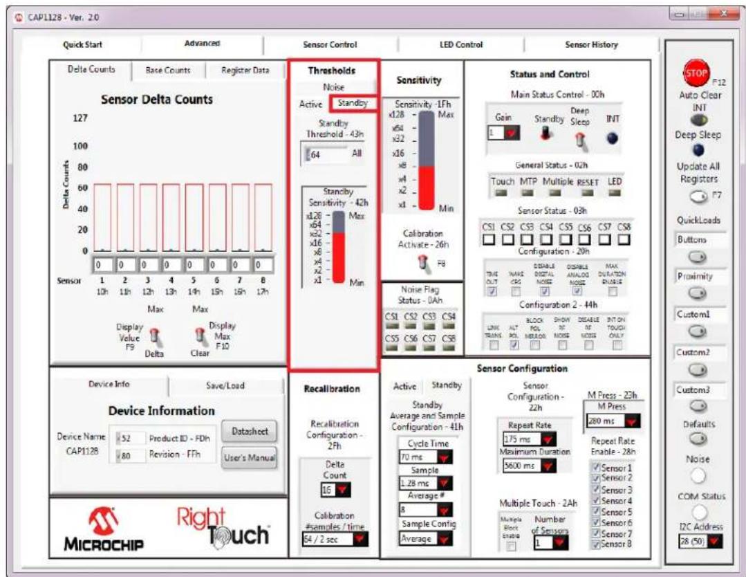
4.10.2 Standby Tab
The Standby tab of the Advanced window's Thresholds section shown in Figure 4.13, contains sensor input controls for the Standby power state.
text_image
CAP1128 - Ver. 20 Quick Start Advanced Sensor Control LED Control Sensor History Delta Counts Base Counts Register Data Sensor Delta Counts 127 100 80 60 40 20 0 0 0 0 0 0 0 0 0 0 0 0 0 0 0 0 0 0 0 0 0 0 0 0 0 0 0 0 0 0 0 0 0 0 0 0 0 0 0 0 0 0 0 0 0 0 0 0 0 0.5x1.5x2.5x3.5x4.5x5.5x6.5x7.5x8.5x9.5x10.5x11.5x12.5x13.5x14.5x15.5x16.5x17.5x18.5x19.5x20.5x21.5x22.5x23.5x24.5x25.5x26.5x27.5x28.5x29.5x30.5x31.5x32.5x33.5x34.5x35.5x36.5x37.5x38.5x39.5x40.5x41.5x42.5x43.5x44.5x45.5x46.5x47.5x48.5x49.5x50.5x51.5x52.5x53.5x54.5x55.5x56.5x57.5x58.5x59.5x60.5x61.5x62.5x63.5x64.5x65.5x66.5x67.5x68.5x69.5x70.5x71.5x72.5x73.5x74.5x75.5x76.5x77.5x78.5x79.5x80.5x81.5x82.5x83.5x84.5x85.5x86.5x87.5x88.5x89.5x90.5x91.5x92.5x93.5x94.5x95.5x96.5x97.5x98.5x99.5x100. Sensitivities: Sensitivity - 1Fh Max Standby Threshold - 43h 64 All Standby Sensitivity - 42h x128 Max x28 Min x4 Min x6 Min x8 Min x1 Min x2 Min x3 Min x4 Min x6 Min x8 Min x1 Min x2 Min x3 Min x4 Min x6 Min x8 Min x1 Min x2 Min x3 Min x4 Min x6 Min x8 Min x1 Min x2 Min x3 Min x4 Min x6 Min x8 Min x1 Min x2 Min x3 Min x4 Min x6 Min x8 Min x1 Min x2 Min x3 Min x4 Min x6 Min x8 MIN e- Noise Flag Status - 0Ah CS1 CS2 CS3 CS4 CS5 CS6 CS7 CS8 CS8 CS9 CS10 CS11 CS12 CS13 CS14 CS15 CS16 CS17 CS18 CS19 CS20 CS21 CS22 CS23 CS24 CS25 CS26 CS27 CS28 CS29 CS30 CS31 CS32 CS33 CS34 CS35 CS36 CS37 CS38 CS39 CS40 CS41 CS42 CS43 CS44 CS45 CS46 CS47 CS48 CS49 CS50 CS51 CS52 CS53 CS54 CS55 CS56 CS57 CS58 CS69 CS70 CS71 CS72 CS73 CS74 CS75 CS76 CS77 CS78 CS79 CS80 CS81 CS82 CS83 CS84 CS85 CS86 CS87 CS88 CS89 CS90 CS91 CS92 CS93 CS94 CS95 CS96 CS97 CS98 CS99 C#N #L#M#O#o#o#o#o#o#o#o#o#o#o#o#o#o#o#o#o#o#o#o#o#o#o#o#o#o#o#o#o#o#o#o#o#o#o#o#o#o#o#o#o#o#o#o#o#o#o#o#o#o#o# o# Status and Control: Main Status Control - 0Oh Goin Standby Deep Sleep INT General Status - 02h Touch MTP Multiple RESET LED Sensor Status - 03h TS1CS2CS3CS4CS5CS6CS7CS8Configuration - 20h TRUE MAKE DISABLE DISABLE MAX DURATION Configuration 2 - 4H LINK ALT BLOCK SHOW DISABLE INT ON SWITCH ONLY LINK TRAIL POL NOO NOO NOO NOO NOO NOO NOO NOO NOO NOO NOO NOO NOO NOO NOO NOO NOO NOO NOO NOO NOO NOO NOO NOO NOO NOO NOO NOO NOO NOO NOO NOO NOO NOO NOO NOO NOO NOO NOO NOO NOO NOO NOO NOO NOO NOO NOO NOO NOO NOO NO OYIANTINICAM Customl CustommCustmCustmCustmCustmCustmCustmCustmCustmCustmCustmCustmCustmCustmCustmCustmCustmCustmCustmCustmCustmCustmCustmCustmCustmCustmCustmCustmCustmCustmCustmCustmCustmCustmCustn Defaults Noise COM Status I2C Address 28 (S) Device Info Save/Load Device Information Device Name Product ID FDh Datasheet CAP112B 80 Revision FFh User's Manual MicroCHIP Right TouchFigure 4.13 Thresholds Control Panel - Standby Tab Displayed
The Standby Threshold defines the delta count threshold level for all sensor inputs when the device is in the Standby state. There is also a Standby Sensitivity bar that affects the Standby Sensitivity Register (42h).
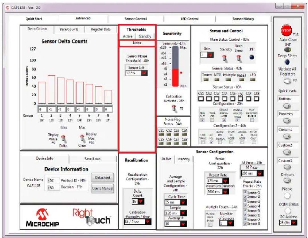
4.10.3 Noise Tab
The Noise tab of the Main window's Thresholds section shown in Figure 4.14, contains the threshold used to detect noise. The Sensor Noise Thresholds are a percentage of the Sensor Thresholds on the Active tab.
text_image
CAP1128 - Ver. 2.0 Quick Start Advanced Sensor Control LED Control Sensor History Delta Counts Base Counts Register Data Sensor Delta Counts 127 100 80 60 40 20 0 -1 -1 -1 -1 -1 -1 -1 -1 -1 0 -1 0 -1 0 0 0 0 Sensor Max Display Value F9 Delta Clear Thresholds Active Standby Noise Sensor Noise Threshold - 38h Sensor 1-8 37.5% Sensitivity Sensitivity -1fh Max xL28 - x64 xL2 x16 x8 x4 x2 x1 Min Calibration Activate - 26h FB Status and Control Main Status Control - 00h Gain Standby Deep Sleep INT General Status - 02h Touch MTP Multiple RESET LED Sensor Status - 03h CS1 CS2 CS3 CS4 CS5 CS6 CS7 CS8 Configuration - 20h DISABLE INACTIVE MAX TIME OUT DYNAMIC ANALOG ENABLE CONFIGURATION 2 - 44h LINK AUT BLOCK SHOWN INSULIE INT ON TRANS POL ERROR NOSE ONLY ✓ ✓ ✓ ✓ ✓ ✓ ✓ ✓ ✓ ✓ ✓ ✓ ✓ ✓ ✓ ✓ ✓ ✓ ✓ ✓ ✓ ✓ ✓ ✓ ✓ ✓ ✓ ✓ ✓ ✓ ✓ ✓ ✓ ✓ ✓ ✓ ✓ ✓ ✓ ✓ ✓ ✓ ✓ ✓ ✓ ✓ ✓ ✓ ✓ ✓ ✓ ✓ ✓ ✓ ✓ ✓ ✓ ✓ ✓ ✓ ✓ ✓ ✓ ✓ ✓ ✓ ✓ ✓ ✓ ✓ ✓ ✓ ✓ ✓ ✓ ✓ ✓ ✓ ✓ ✓ ✓ ✓ ✓ ✓ ✓ ✓ ✓ ✓ ✓ ✓ ✓ ✓ ✓ ✓ ✓ ✓ ✓ ✓ ✓ ✓ Device Info Save/Load Device Information Device Name 52 Product ID - FDh Dataheet CAP112B 80 Revision - FFh User's Manual MicroCHIP Right Touch™ Recalibration Recalibration Configuration - 27h Delta Count 16 Calibration #samples / time 64 / 2 sec Sensor Configuration Active Standby Sensor Configuration - 22h M Press - 23h M Press 280 ms Repeat Rate 175 ms Maximum Duration 5600 ms Repeat Rate Enable - 28h Sensor 1 Sensor 2 Sensor 3 Sensor 4 Sensor 5 Sensor 6 Sensor 7 Sensor 8 Multiple Block Enable Number of Sensors L Average and Sample Configuration - 24h Cycle Time 35 ms Sample 1.28 ms Average # 16 Multiple Touch - 2Ah Multiple Block Enable Number of Sensors L Source: Auto Clear INT Deep Sleep Update All Registers QuickLoads Buttons Proximity Custom1 Custom2 Custom3 Defaults Noise COM Status I2C Address 28 (50)Figure 4.14 Thresholds Control Panel - Noise Tab Displayed
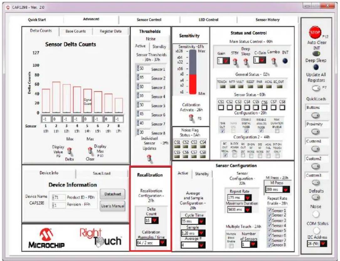
4.11 Recalibration Configuration Control Panel
On the Advanced window below the Thresholds section is the Recalibration Configuration section shown in Figure 4.15.
text_image
CAP1298 - Ver. 2.0 Quick Start Advanced Sensor Control LED Control Sensor History Delta Counts Base Counts Register Data Sensor Delta Counts 127 100 80 60 40 20 0 -1 1 2 3 4 5 6 7 8 Sensor Max Max Display Value F9 Display Max F10 Thresholds Noise Active Standby Sensor Thresholds - 30h - 37h 50 Sensor 1 65 Sensor 2 60 Sensor 3 55 Sensor 4 50 Sensor 5 45 Sensor 6 40 Sensor 7 30 Sensor 8 Individual Sensor - 2Fh Updates Sensitivity Sensitivity -1Fh Max x128 x64 x32 x16 x8 x4 x2 x1 Min Calibration Activate - 26h FB Status and Control Main Status Control - 00h Gain Deep Gain C-Gain Combo INT General Status - 02h TOUCH NTP MULT RESET PWR ACAL BC_OUT Sensor Status - 03h CS1 CS2 CS3 CS4 CS5 CS6 CS7 CS8 Configuration - 20h TIME OUT DISABLE ORANGE MAX DURATION ENABLE Configuration 2 - 44h BC BLOCK BC SHOWN DIE ACAL BIT/ON OUT POWER OUT RF TAIL TOUGH RECAL CTRL INT NOSE INT ONLY Device Info Save/Load Device Information Device Name 71 Product ID - PDh Datasheet CAP129B Revision - FFh User's Manual Recalibration Recalibration Configuration - 2Fh Delta Count 16 Calibration #samples / time 64 / 2 sec Sensor Configuration Sensor Configuration - 22h M Press - 23h Repeat Rate 280 ms Maximum Duration 5600 ms Repeat Rate Enable - 28h Sample 1.28 ms Average # Multiple Touch - 2Ah Number of Sensors L Number of Sensors 1 S12C Address 28 (50) STOP F12 Auto Clear INT Deep Sleep Update All Registers QuickLoads Buttons Proximity Custom1 Custom2 Custom3 Defaults Noise COM Status I2C AddressFigure 4.15 Recalibration Configuration Control Panel
The 'Calibration #samples / time' drop-down menu allows selection of the update time and number of samples related to the recalibration routine. Negative delta count allows selection of the number of consecutive negative delta counts necessary to trigger a digital recalibration. Both of these controls affect the Recalibration Configuration Register (2Fh).
4.12 Status and Control Panel
The Status and Control section of the Main window shown in Figure 4.16, displays the current Sensor Status register value and the General Status register. It also provides control and display of the device interrupt, power states, and advanced configuration options.
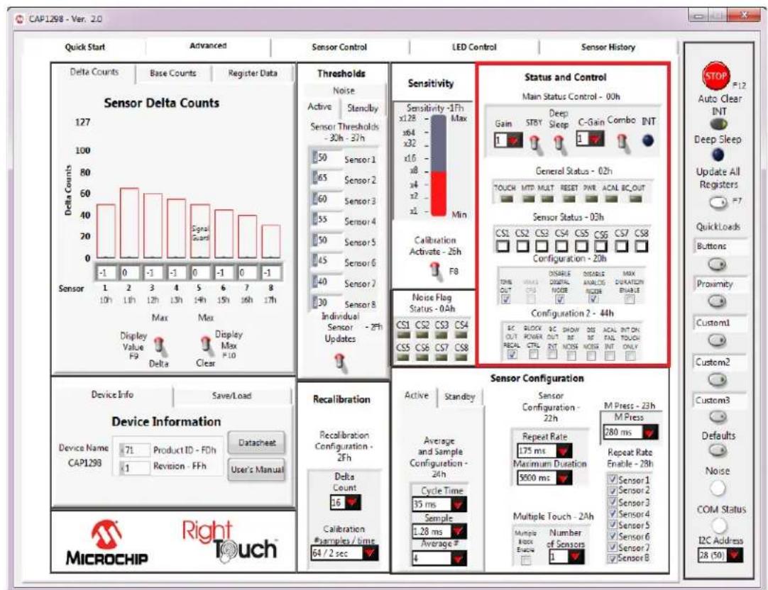
Figure 4.16 Status and Control Panel
When the sensor's signal exceeds the threshold, the Sensor Status section will change the corresponding square button to a dark square. Depending on configuration settings, indicators in the General Status section may turn blue (or a lighter color, depending on the PC settings) when the criteria for the indicator is met.
If the Auto Clear INT button on the Panel (see Section 4.5, "Communications Status and Control Panel") is enabled (dark gray), the INT indicator, General Status section, and the Sensor Status section are continuously cleared. This allows the user to see only the current state of the device.. If the Auto Clear INT button is disabled (light gray), the user must manually clear interrupts by clicking the INT indicator or the Auto Clear INT button. This allows for a more realistic demonstration of the behavior of the device's registers between host reads and writes of the INT bit.
4.12.1 Power States
Please refer to the device datasheet for details regarding the different power states. The software switches work as follows:
The Standby switch toggles between the Standby and Fully Active states.
The Deep Sleep switch puts the device into the Deep Sleep state. To exit Deep Sleep, click anywhere on the GUI to display the message shown in Figure 4.17. There is also a timeout that will display the message shown in Figure 4.18.

text_image
Control Panel locked while in Deep Sleep. SMBus communication wakes device. Continue in Deep Sleep Exit Deep SleepFigure 4.17 Deep Sleep Message
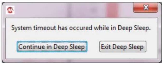
text_image
System timeout has occurred while in Deep Sleep. Continue in Deep Sleep Exit Deep SleepFigure 4.18 Deep Sleep Timeout Message
4.12.2 Configuration and Configuration 2
The Configuration section of 'Status and Control' allows the user to enable and disable bits in the Configuration Register (20h). The Configuration 2 section allows the user to enable and disable bits in the Configuration 2 Register (44h). These registers control the general global functionality of the device. Refer to the datasheet for details.
4.13 Sensor Configuration Control Panel
The Sensor Configuration section shown in Figure 4.19, allows the user to adjust the configuration registers for the sensors. These controls change the response of the sensors to suit the environment, application, and desired response in the Fully Active and Standby states.
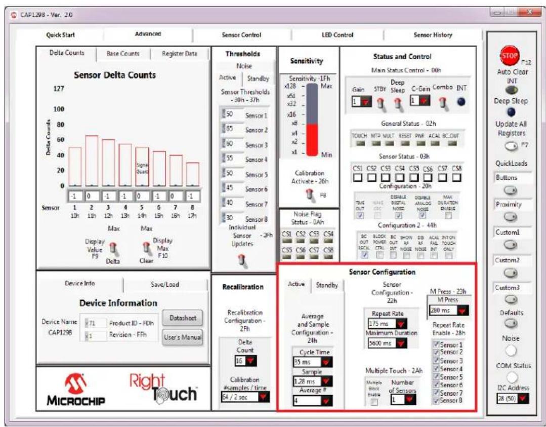
Figure 4.19 Sensor Configuration Control Panel
The Sensor Configuration section contains options for the Averaging and Sampling Configuration Register (24h), which adjust the averaging and cycle time for sensor inputs that are active in the Fully Active state. The Standby Tab controls affect the Standby Configuration Register (41h), which controls averaging and cycle time for sensor inputs that are active in the Standby state.
Controls in the Sensor Configuration section affect the Sensor Configuration Register (22h). Repeat rate settings determine whether one or more interrupts are sent per sensor activation and the duration between interrupts. Maximum duration settings determine maximum time a sensor can be activated before the sensor input is recalibrated.
The M Press control affects the Sensor Configuration 2 Register (23h). The M Press setting delineates the time duration difference between a touch versus a press-and-hold event. If the press is longer than the M Press time, it is considered a press-and-hold.
Controls in the Multiple Touch section affect the Multiple Touch Configuration Register (2Ah). Multiple touch settings determine how simultaneous touches to multiple buttons .are handled. Remember to check the 'Multiple Block Enable' box to enable this feature. In the actual device, the 'enable' bit must also be set in the register to enable the feature.
Controls in the Repeat Rate Enable section affect the Repeat Rate Enable Register (28h). When checked, the repeat rate defined in the Sensor Configuration section is enabled for the button.
5 GUI Sensor Control Tab
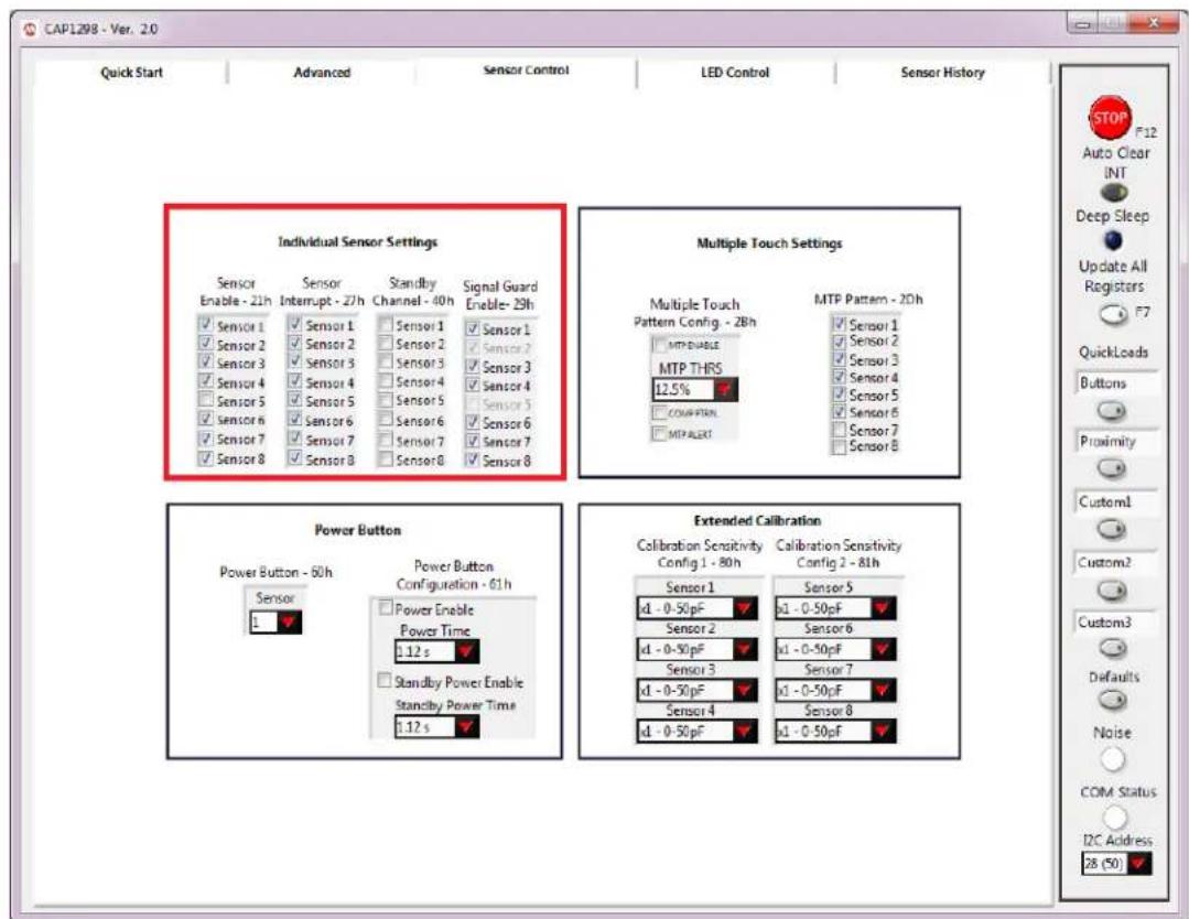
The Sensor Control tab provides the detailed controls for individual sensor inputs. Figure 5.1 shows the default view for the CAP1298 Evaluation Board.

text_image
CAP1298 - Ver. 2.0 Quick Start Advanced Sensor Control LED Control Sensor History Individual Sensor Settings CAP129x Only Sensor Enable - 21h Sensor Interrupt - 27h Standby Channel - 40h Signal Guard Enable - 29h Sensor 1 Sensor 1 Sensor 1 Sensor 2 Sensor 2 Sensor 3 Sensor 3 Sensor 4 Sensor 4 Sensor 5 Sensor 5 Sensor 5 Sensor 6 Sensor 6 Sensor 6 Sensor 7 Sensor 7 Sensor 7 Sensor 8 Multiple Touch Settings Multiple Touch Pattern Config. - 2Bh MTP Pattern - 2Dh Sensor 1 Sensor 2 Sensor 3 Sensor 4 Sensor 5 Sensor 6 Sensor 7 Sensor 8 Power Button Power Button - 60h Sensor 1 Power Button Configuration - 61h Power Enable Power Time 1.12 s Standby Power Enable Standby Power Time 1.12 s Extended Calibration Calibration Sensitivity Config 1 - 80h Calibration Sensitivity Config 2 - 81h Sensor 1 x1 - 0-50pF x1 - 0-50pF Sensor 2 x1 - 0-50pF Sensor 3 x1 - 0-50pF Sensor 4 x1 - 0-50pF x1 - 0-50pF CAP129x Only CAP129x Only STOP F12 Auto Clear INT Deep Sleep Update All Registers F7 QuickLoads Buttons Proximity Custom1 Custom2 Custom3 Defaults Noise COM Status I2C Address G8 (50)Figure 5.1 Sensor Control Tab for the CAP1188 Evaluation Board
The Sensor Control Panel has 2 sections: individual sensor inputs (see Section 4.1) and all sensor inputs (see Section 5.1).
5.1 All Sensor Input Settings
The All Sensor Settings display, shown in Figure 5.2, has the controls for all the sensor inputs. A check mark represents a '1' in logic.
The 'Sensor Enable' column determines which sensors are scanned in Active mode.
The 'Sensor Interrupt' column determines which sensors produce an interrupt when a touch is detected.
The 'Standby Channel' column determines which sensors are scanned in Standby mode. For the CAP12xx devices, this also determines which sensors will be scanned using the Combo Gain settings when in Combo mode.
The 'Signal Guard Enable' column is only available on CAP129x devices and determines which sensors will have the signal guard enabled during their scan.
text_image
CAP1298 - Ver. 2.0 Quick Start Advanced Sensor Control LED Control Sensor History Individual Sensor Settings Sensor Enable - 21h Sensor Interrupt - 27h Standby Channel - 40h Signal Guard Enable- 29h ✓ Sensor 1 ✓ Sensor 1 ✓ Sensor 1 ✓ Sensor 1 ✓ Sensor 2 ✓ Sensor 2 ✓ Sensor 2 ✓ Sensor 2 ✓ Sensor 3 ✓ Sensor 3 ✓ Sensor 3 ✓ Sensor 3 ✓ Sensor 4 ✓ Sensor 4 ✓ Sensor 4 ✓ Sensor 4 ✓ Sensor 5 ✓ Sensor 5 ✓ Sensor 5 ✓ Sensor 5 ✓ Sensor 6 ✓ Sensor 6 ✓ Sensor 6 ✓ Sensor 6 ✓ Sensor 7 ✓ Sensor 7 ✓ Sensor 7 ✓ Sensor 7 ✓ Sensor 8 ✓ Sensor 8 ✓ Sensor 8 Multiple Touch Settings Multiple Touch Pattern Config - 28h MTP Pattern - 20h MTP ENABLE MTP THRS 12.5% COMPUTEN MTP ALERT MTP Pattern - 20h ✓ Sensor 1 ✓ Sensor 2 ✓ Sensor 3 ✓ Sensor 4 ✓ Sensor 5 ✓ Sensor 6 ✓ Sensor 7 ✓ Sensor 8 Power Button Power Button - 50h Power Button Configuration - 61h Sensor 1 Power Enable Power Time 1:12 s Standby Power Enable Standby Power Time 1:12 s Extended Calibration Calibration Sensitivity Config 1 - 80h Calibration Sensitivity Config 2 - 81h Sensor 1 x1 - 0-50pF Sensor 5 Sensor 2 x1 - 0-50pF Sensor 6 Sensor 3 x1 - 0-50pF Sensor 7 Sensor 4 x1 - 0-50pF Sensor 8 x1 - 0-50pF x1 - 0-50pF x1 - 0-50pF x1 - 0-50pF x1 - 0-50pF x1 - 0-50pF x1 - 0-50pF x1 - 0-50pF x1 - 0-50pF x1 - 0-50pF x1 - 0-50pF x1 - 50pFFigure 5.2 All Sensor Settings
5.2 Multiple Touch Pattern Settings
5.2.1 MTP Tab
The MTP tab of the Main window's Thresholds section shown in Figure 5.3, contains multiple touch pattern configuration controls. The MTP Thresholds are a percentage of the Sensor Thresholds on the Active tab.

text_image
CAP1298 - Ver. 2.0 Quick Start Advanced Sensor Control LED Control Sensor History Individual Sensor Settings Sensor Enable - 21h Sensor Interrupt - 27h Standby Channel - 40h Signal Guard Enable- 29h ✓ Sensor 1 ✓ Sensor 1 ✓ Sensor 1 ✓ Sensor 2 ✓ Sensor 2 ✓ Sensor 2 ✓ Sensor 3 ✓ Sensor 3 ✓ Sensor 3 ✓ Sensor 4 ✓ Sensor 4 ✓ Sensor 4 ✓ Sensor 5 ✓ Sensor 5 ✓ Sensor 5 ✓ Sensor 6 ✓ Sensor 6 ✓ Sensor 6 ✓ Sensor 7 ✓ Sensor 7 ✓ Sensor 7 ✓ Sensor 8 ✓ Sensor 8 ✓ Sensor 8 Multiple Touch Settings Multiple Touch Pattern Config. - 2Bh MTP Pattern - 2Dh ✓ Sensor 1 ✓ Sensor 2 ✓ Sensor 3 ✓ Sensor 4 ✓ Sensor 5 ✓ Sensor 6 ✓ Sensor 7 ✓ Sensor 8 Power Button Power Button - 60h Power Button Configuration - 61h Sensor Power Enable Power Time Standby Power Enable Standby Power Time Extended Calibration x1 - 0-50pF Calibration Sensitivity Config 1 - 80h Calibration Sensitivity Config 2 - 81h Sensor 1 Sensor 5 x1 - 0-50pF x1 - 0-50pF Sensor 2 Sensor 6 x1 - 0-50pF x1 - 0-50pF Sensor 3 Sensor 7 x1 - 0-50pF x1 - 0-50pF Sensor 4 Sensor 8 x1 - 0-50pF x1 - 0-50pF STOP F12 Auto Clear INT Deep Sleep Update All Registers F7 QuickLoads Buttons Proximity Custom1 Custom2 Custom3 Defaults Noise COM Status I2C Address 28 (50)Figure 5.3 Multiple Touch Pattern Options
5.3 Extended Calibration Ranges
When using a CAP129x device, the Sensor Control window will display an Extended Calibration section, shown in Figure 5.1, for choosing the calibration sensitivity settings for each sensor. This allows the user to reduce the internal capacitance used while generating the sensing waveform (which will increase sensitivity), but the sensor must fall within the selected capacitance range or it will not calibrate.
5.4 Power Button
When using a CAP12xx device, the Sensor Control window will display a Power Button section, shown in Figure 5.1, for enabling a sensor to have a delay before registering a press. This allows systems to force the user to press for an extended period to verify that a critical action was meant to be performed. For example: if this is used to power on and off the application, setting a minimum press period with these options minimizes the chance of a user accidentally pressing the sensor.
6 GUI LED Control Tab
The LED Control tab provides the detailed controls for the LEDs. Figure 6.1 shows the default view for the CAP1188 evaluation board.
The CAP12xx devices do not have LED drivers, so this window will not contain any options. The LEDs on the evaluation board are being driven by the PIC16F145x microcontroller.an EVB using the CAP1188 device.

text_image
CAP1128 - Ver. 2.0 Quick Start Advanced Sensor Control LED Control Sensor History LED 1 LED 1 Control Control Drive Low Linked Polarity Output Type Inverted Open drain Mirror Linked Transition Normal Normal Behavior Direct LED Status - 04h LED 8 ALL LED Controls LED Behavior Configuration Pulse 1, Pulse 2, Breathe, Direct LED Pulse and Breathe Duty Cycles - 90h - 93h Maximum Pulse 1 100% Minimum Pulse 1 0% Maximum Pulse 2 100% Minimum Pulse 2 0% Maximum Minimum Breathe 0% Maximum Minimum Direct 0% LED Pulse Periods - 84h - 86h Pulse 1 Start Trigger 1024 ms Touch Pulse 2 Period 540 ms Pulse 1 Count 5 Ramp Alert Pulse 2 Count 1 Direct Rates - 94h - 95h Rise Rate 0 s Off Delay Fall Rate 0 s 0.25 s STOP F12 Auto Clear INT Deep Sleep Update All Registers F7 QuickLoads Buttons Proximity Custom1 Custom2 Custom3 Defaults Noise COM Status I2C Address 28 (50) LED Pulse1 Response Graph LED Output (%) 100 Time (ms) -1 500 1000 1500 2000 2500 3000 3500 4000 4500 5120 LED Pulse2 Response Graph LED Output (%) 100 Time (ms) -1 500 1000 1500 2000 2500 3000 3500 4000 4500 5120 LED Breathe Response Graph LED Output (%) 100 Time (ms) -1 500 1000 1500 2000 2500 3000 3500 4000 4500 5120 LED Direct Response Graph LED Output (%) 100 Time (ms) -1 20 40 60 80 100 120 140 160 180 200 220 240Figure 6.1 LED Control Tab for the CAP1188 Evaluation Board
The LED Control Panel has 3 sections: individual (see Section 6.1), all (see Section 6.3), LED behavior configuration (see Section 6.4), and graphs.
6.1 Individual LED Settings
To access individual LED controls, click the respective LED button on the left side of the control panel or use the scroll switch above the buttons. The control panel will then display controls for the selected LED. Figure 6.2 shows the control panel after the 'LED 1' button was clicked.

text_image
CAP1128 - Var. 20 Quick Start Advanced Sensor Control LED Control Sensor History LED 1 LED 1 Control Control Drive Low Linked Polarity Output Type Inverted Open-drain Mirror Linked Transition Normal Normal Behavior Direct All LED Controls LED Behavior Configuration Pulse 1, Pulse 2, Breathe, Direct LED Pulse and Breathe Duty Cycles - 90h - 93h Maximum Pulse 1 Minimum Pulse 1 Maximum Pulse 2 Minimum Pulse 2 Maximum Minimum Breathe Maximum Minimum Direct Maximum Maximum Rise Rate Off Delay Fall Rate LED Pulse Periods - 84h - 88h LED Pulse Configuration - 88h Pulse 1 Start Trigger Touch Pulse 1 Count 5 Ramp Alert Pulse 2 Count 1 Direct Rates - 94h - 95h LED Pulse1 Response Graph LED Output (%) 100 100 100 100 100 100 LED Pulse2 Response Graph LED Output (%) 100 100 50 50 50 50 LED Direct Response Graph LED Output (%) 100 100 50 50 50 LED Direct Response Graph LED Output (%) 100 100 50 50 50Figure 6.2 Individual LED Settings
6.2 LED Status
An indicator in the LED Status section changes color when the LED behavior has completed its cycle and the LED is in host control mode. The indicator for an LED is disabled when the LED is linked to a sensor.
If the Auto Clear INT button on the Panel (see Section 4.5, "Communications Status and Control Panel") is enabled (dark gray), the LED Status indicators are continuously cleared. If the Auto Clear INT button is disabled (light gray), the user must manually clear interrupts by clicking the Auto Clear INT button or the INT indicator on the Main Tab (Section 4.12, "Status and Control Panel").
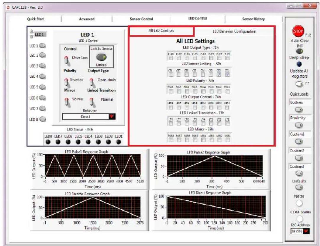
6.3 All LED Settings
The 'All LED Settings' display, shown in Figure 6.3, displays a view of the LED controls for all the LEDs. A check mark represents a '1' in logic.
Note: This control panel does not include LED behavior. Use the individual settings panels instead.
text_image
CAP1128 - Ver. 2.0 Quick Start Advanced Sensor Control LED Control Sensor History LED 1 LED 1 Control Control Drive Low Linked Polarity Output Type Inverted Open-drain Mirror Linked Transition Normal Normal Behavior Direct LED Status - 04h LED Output (%) 100 LED Pulse? Response Graph LED Output (%) 100 LED Direct Response Graph LED Output (%) 100 LED Pulse? Response Graph LED Output (%) 100 LED Direct Response Graph LED Output (%) 100 LED Pulse? Response Graph LED Output (%) 100 LED Direct Response GraphFigure 6.3 All LED Settings
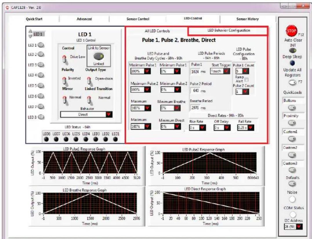
6.4 LED Behavior Configuration Control Panel
The LED Behavior Configuration Control Panel, shown in Figure 6.4, provides controls for the 4 different types of behaviors available to the LED drivers.
text_image
CAP1128 - Ver. 20 Quick Start Advanced Sensor Control LED Control Sensor History LED 1 LED 1 Control Control Link to Sensor Drive Low Linked Polarity Output Type Inverted Open-drain Mirror Linked Transition Normal Normal Behavior Direct LED Status - 04h LED B LED D LED E LED F LED G LED H LED I ALL LED Controls LED Behavior Configuration Pulse 1, Pulse 2, Breathe, Direct LED Pulse and Breathe Duty Cycles - 90h - 93h LED Pulse Periods - 84h - 85h LED Pulse Configuration - 86h Maximum Pulse 1 Minimum Pulse 1 Pulse 1 Start Trigger Pulse 1 Count Maximum Pulse 2 Minimum Pulse 2 Pulse 2 Period 640 ms Maximum Minimum Breathe Breathe Period 2976 ms Maximum Minimum Direct Rice Rate Off Delay Fail Rate 0 s 0 s 0.25 s Direct Rates - 94h - 95h LED Pulse1 Response Graph LED Output4 (%) 100% 50% 0% -1 500 1000 1500 2000 2500 3000 3500 4000 4500 5120 Time (ms) LED Pulse2 Response Graph LED Output6 (%) 100% 50% 0% -1 100 200 300 400 500 600-640 Time (ms) LED Direct Response Graph LED Output8 (%) 100% 50% 0% -1 20 40 60 80 100 120 140 160 180 200 220 250 Time (ms) LED Breathe Response Graph LED Output9 (%) 100% 50% 0% -1 20-40-60-80-100-120-140-160-180-200-220-250-28 (50) LED Output10 (%) 100% 50% 0% -1Figure 6.4 LED Behavior Configuration Control Panel
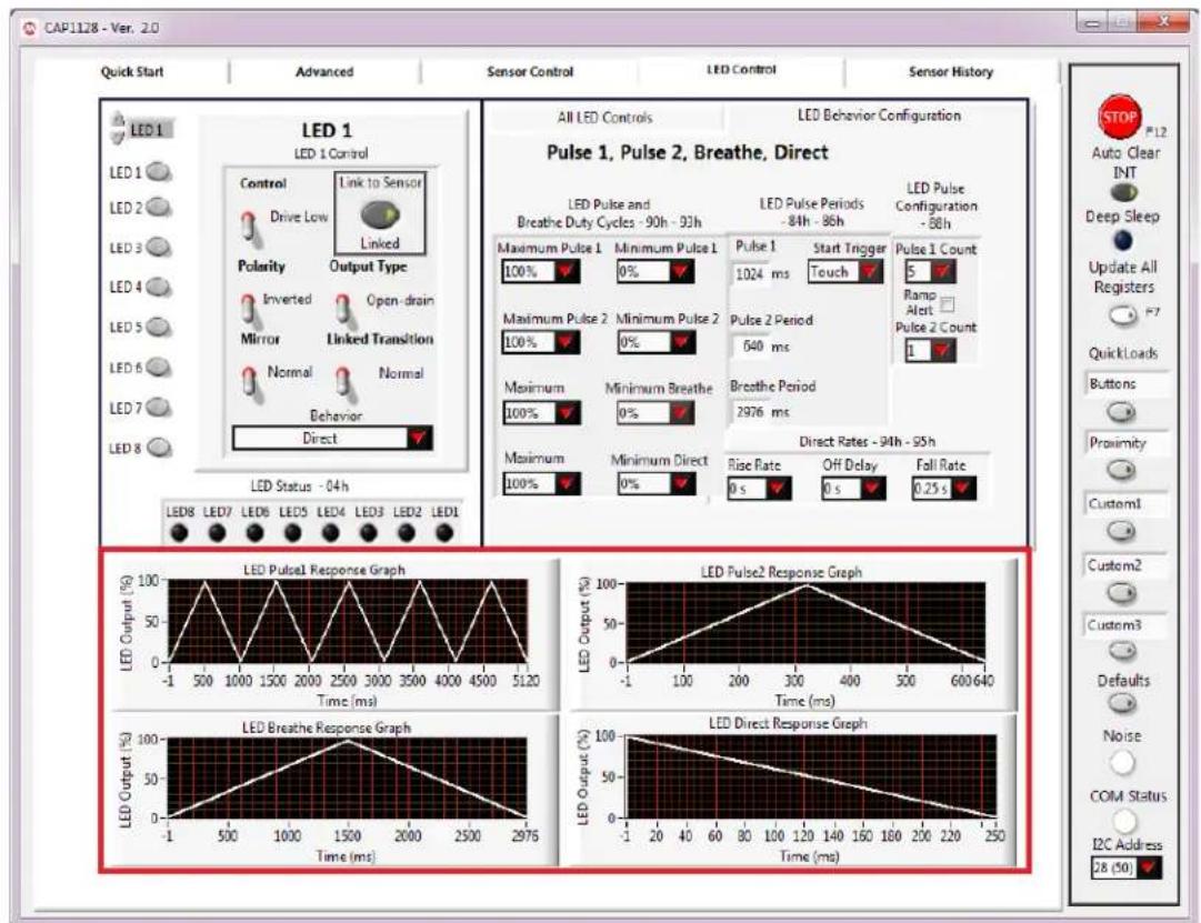
The graphs, shown in Figure 6.5, at the bottom of the LED Control tab display of how the behaviors will look based on the selections.
text_image
CAP1128 - Ver. 2.0 Quick Start Advanced Sensor Control LED Control Sensor History LED 1 LED 1 Control Control Drive Low Linked Polarity Output Type Inverted Open-drain Mirror Linked Transition Normal Normal Behavior Direct LED Status - 04h All LED Controls LED Behavior Configuration Pulse 1, Pulse 2, Breathe, Direct LED Pulse and Breathe Duty Cycles - 90h - 93h Maximum Pulse 1 Minimum Pulse 1 Maximum Pulse 2 Minimum Pulse 2 Maximum Minimum Breathe Maximum Minimum Direct Maximum Minimum Pulse 1 Maximum Pulse 2 Maximum Pulse 2 Maximum Maximum Pulse 2 Maximum Pulse 2 Maximum Pulse 2 Maximum Pulse 2 Maximum Pulse 2 Maximum Pulse 2 Maximum Pulse 2 Maximum Pulse 2 Maximum Pulse 2 Maximum Pulse 2 Maximum Pulse 2 Maximum Pulse 2 Maximum Pulse 2 Maximum Pulse 2 Maximum Pulse 2 Maximum Pulse 2 Maximum Pulse 2 Maximum Pulse 2 Maximum Pulse 2 Maximum Pulse 2 Maximum Pulse 1 Maximum Pulse 1 Maximum Pulse 1 Maximum Pulse 1 Maximum Pulse 1 Maximum Pulse 1 Maximum Pulse 1 Maximum Pulse 1 Maximum Pulse 1 Maximum Pulse 1 Maximum Pulse 1 Maximum Pulse 1 Maximum Pulse 1 Maximum Pulse 1 Maximum Pulse 1 Maximum Pulse 1 Maximum Pulse 1 Maximum Pulse 1 Maximum Pulse 1 Maximum Pulse 1 Maximum Pulse 2 Maximum Pulse 2 Maximum Pulse 2 Maximum Pulse 2 Maximum Pulse 2 Maximum Pulse 2 Maximum Pulse 2 Maximum Pulse 2 Maximum Pulse 2 Maximum Pulse 2 Maximum Pulse 2 Maximum Pulse 2 Maximum Pulse 2 Maximum Pulse 2 Maximum Pulse 2 Maximum Pulse 2 Maximum Pulse 2 Maximum Pulse 2 Maximum Pulse 2 Maximum Pulse 300-350-400-450-500-550-600-650-700-750-800-850-900-950-100-105-110-115-120-125-130-135-140-145-150-155-160-165-170-175-180-185-190-195-200-205-210-215-220-225-230-235-240-245-250- LED Output (%) LED Output (%) LED Output (%) LED Output (%) LED Output (%) LED Output (%) LED Output (%) LED Output (%) LED Output (%) LED Output (%) LED Output (%) LED Output (%) LED Output (%) LED Output (%) LED Output (%) LED Output (%) LED Output (%) LED Output (%) LED Output (%) LED Output (%) LED Output (%) LED Output (%) LED Output (%) LED Output (%) LED Output (%) LED Output (%)Figure 6.5 LED Behavior Configuration Graphs
Controls in the LED Pulse and Breathe Duty Cycles section affect the LED Duty Cycles Registers (90h - 93h). Controls in the LED Pulse Periods section affect the LED Period Registers (84h - 86h). Controls in the LED Behavior Configuration section affect the LED Configuration Register (88h).
The LED Pulse1 Response Graph reflects the settings selected for the Pulse 1 behavior (Maximum Pulse 1, Minimum Pulse 1, Pulse 1 Period, and Pulse 1 Count). The LED Pulse2 Response Graph reflects settings selected for Pulse 2 behavior.
Controls in the LED Direct Rates section affect the LED Direct Ramp Rates Register (94h) and LED Off Delay Register (95h).
The LED Direct Rate Response Graph reflects the settings in the LED Direct Rates section.
7 GUI Sensor History Tab
The Sensor History tab displays a graph of sensor delta counts and allows the data to be saved to a file. Figure 7.1 shows the default view for the CAP1xxx evaluation board.
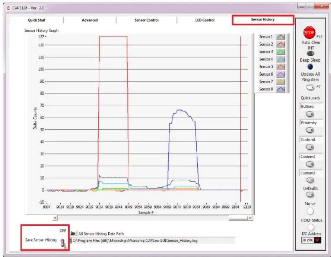
line
| Sample # | Delta Counts | | -------- | ------------ | | 9034 | 127 | | 9074 | 65 |Figure 7.1 Sensor History Tab for the CAP1xxx Evaluation Board
As sensors are touched, delta counts display on the graph..
To save the delta counts over a period of time, ensure the desired path and filename are showing in the 'All Sensor History Data Path' box. To change this: Manually type in a path, or select the folder icon to browse to the desired folder and file. The file should be named with the extension ".csv". Once a file name has been chosen, click the "Save Sensor History" switch so it's in the up (Saving) position. The software will start logging data into the selected file.
Note 7.1 If a file with the same name already exists, the file will be overwritten and old data will be lost.
After generating data for a desired period of time, click the 'Save Sensor History' switch so it's in the down (OFF) position (see Figure 7.1).
The data is saved in a .csv format, as shown in Figure 7.2.
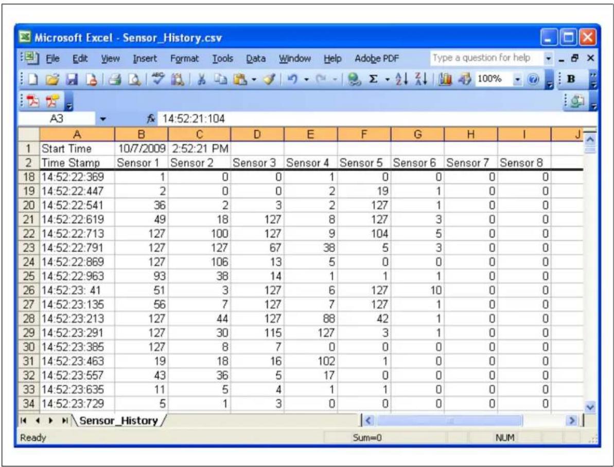
Figure 7.2 Sample Sensor_History.csv File
8 Troubleshooting
8.1 GUI Controls Unresponsive After Installation
Restart the computer. In some cases, a restart is required after installation.
To restore defaults, press the F6 key on the keyboard or click the Defaults button (see Section 4.5.6, "Defaults Button"). Alternatively, unplug the USB mini connector from the CAP1xxx evaluation board, then plug it in again.
8.3 Control Panels Freeze
If the control panels freeze for unknown reasons, communications cannot be stopped, and the program cannot be closed, disconnect the USB cable from the CAP1xxx evaluation board, then close the program. Reconnect the evaluation board, then restart the CAP1xxx GUI.
8.4 Values in GUI Control Panels Don't Match Registers
It's possible that the GUI control panels can get out of sync with the actual register values when disconnecting and reconnecting the CAP1xxx evaluation board. If this occurs, click the Update All Registers button (see Section 4.5.4, "Update All Registers").
8.5 Communications Fail
If the device fails to communicate through the I2C bus, ensure the correct I2C address is displayed on the Communications Status and Control Panel. The CAP11xx evaluation board has a 0 ohm resistor connected between VDD and the ADDR_COM pin, and the CAP12xx devices have a static address that can only be changed at the Microchip Test Facility. So the I2C address should be 28 (50) (0101_000r/w). If an external board has been connected to the evaluation board's 8-pin communications header, a new address may need to be selected. If communications were stopped when the evaluation board was disconnected, click the Run button (see Section 4.5.1, "Stop and Run Buttons").
9 Revision History
Table 9.1 Revision History
| REVISION LEVEL & DATE SECTION/FIGURE/ENTRY CORRECTION | ||
| CAP1xxx Evaluation Board User's Guide, Revision A replaces the previous SMSC documentRightTouch CAP1188 Family EVBUser Manual, Revision 1.0 | ||
Note the following details of the code protection feature on Microchip devices:
• Microchip products meet the specification contained in their particular Microchip Data Sheet.
- Microchip believes that its family of products is one of the most secure families of its kind on the market today, when used in the intended manner and under normal conditions.
- There are dishonest and possibly illegal methods used to breach the code protection feature. All of these methods, to our knowledge, require using the Microchip products in a manner outside the operating specifications contained in Microchip's Data Sheets. Most likely, the person doing so is engaged in theft of intellectual property.
• Microchip is willing to work with the customer who is concerned about the integrity of their code.
- Neither Microchip nor any other semiconductor manufacturer can guarantee the security of their code. Code protection does not mean that we are guaranteeing the product as "unbreakable."
Code protection is constantly evolving. We at Microchip are committed to continuously improving the code protection features of our products. Attempts to break Microchip's code protection feature may be a violation of the Digital Millennium Copyright Act. If such acts allow unauthorized access to your software or other copyrighted work, you may have a right to sue for relief under that Act.
Information contained in this publication regarding device applications and the like is provided only for your convenience and may be superseded by updates. It is your responsibility to ensure that your application meets with your specifications. MICROCHIP MAKES NO REPRESENTATIONS OR WARRANTIES OF ANY KIND WHETHER EXPRESS OR IMPLIED, WRITTEN OR ORAL, STATUTORY OR OTHERWISE, RELATED TO THE INFORMATION, INCLUDING BUT NOT LIMITED TO ITS CONDITION, QUALITY, PERFORMANCE, MERCHANTABILITY OR FITNESS FOR PURPOSE. Microchip disclaims all liability arising from this information and its use. Use of Microchip devices in life support and/or safety applications is entirely at the buyer's risk, and the buyer agrees to defend, indemnify and hold harmless Microchip from any and all damages, claims, suits, or expenses resulting from such use. No licenses are conveyed, implicitly or otherwise, under any Microchip intellectual property rights.
Trademarks
The Microchip name and logo, the Microchip logo, dsPIC, FlashFlex, KEELOQ, KEELOQ logo, MPLAB, PIC, PICmicro, PICSTART, PIC ^32 logo, rfPIC, SST, SST Logo, SuperFlash and UNI/O are registered trademarks of Microchip Technology Incorporated in the U.S.A. and other countries.
FilterLab, Hampshire, HI-TECH C, Linear Active Thermistor, MTP, SEEVAL and The Embedded Control Solutions Company are registered trademarks of Microchip Technology Incorporated in the U.S.A.
Silicon Storage Technology is a registered trademark of Microchip Technology Inc. in other countries.
Analog-for-the-Digital Age, Application Maestro, BodyCom, chipKIT, chipKIT logo, CodeGuard, dsPICDEM, dsPICDEM.net, dsPICworks, dsSPEAK, ECAN, ECONOMONITOR, FanSense, HI-TIDE, In-Circuit Serial Programming, ICSP, Mindi, MiWi, MPASM, MPF, MPLAB Certified logo, MPLIB, MPLINK, mTouch, Omniscient Code Generation, PICC, PICC-18, PICDEM, PICDEM.net, PICkit, PICtail, REAL ICE, rfLAB, Select Mode, SQI, Serial Quad I/O, Total Endurance, TSHARC, UniWinDriver, WiperLock, ZENA and Z-Scale are trademarks of Microchip Technology Incorporated in the U.S.A. and other countries.
SQTP is a service mark of Microchip Technology Incorporated in the U.S.A.
GestIC and ULPP are registered trademarks of Microchip Technology Germany II GmbH & Co. KG, a subsidiary of Microchip Technology Inc., in other countries.
A more complete list of registered trademarks and common law trademarks owned by Standard Microsystems Corporation ("SMSC") is available at: www.smsc.com. The absence of a trademark (name, logo, etc.) from the list does not constitute a waiver of any intellectual property rights that SMSC has established in any of its trademarks.
All other trademarks mentioned herein are property of their respective companies.
© 2013, Microchip Technology Incorporated, Printed in the U.S.A., All Rights Reserved.
ISBN: 9781620776230
QUALITY MANAGEMENT SYSTEM
CERTIFIED BY DNV
=ISO/TS 16949=
Microchip received ISO/TS-16949:2009 certification for its worldwide headquarters, design and wafer fabrication facilities in Chandler and Tempe, Arizona; Gresham, Oregon and design centers in California and India. The Company's quality system processes and procedures are for its PIC® MCUs and dsPIC® DSCs, KEELoo® code hopping devices, Serial EEPROMs, microperipherals, nonvolatile memory and analog products. In addition, Microchip's quality system for the design and manufacture of development systems is ISO 9001:2000 certified.
Worldwide Sales and Service
AMERICAS
Corporate Office
2355 West Chandler Blvd.
Chandler, AZ 85224-6199
Tel: 480-792-7200
Fax: 480-792-7277
Technical Support:
http://www.microchip.com/support
Web Address:
www.microchip.com
Atlanta
Duluth, GA
Tel: 678-957-9614
Fax: 678-957-1455
Austin, TX
Tel: 512-257-3370
Boston
Westborough, MA
Tel: 774-760-0087
Fax: 774-760-0088
Chicago
Itasca, IL
Tel: 630-285-0071
Fax: 630-285-0075
Cleveland
Independence, OH
Tel: 216-447-0464
Fax: 216-447-0643
Dallas
Addison, TX
Tel: 972-818-7423
Fax: 972-818-2924
Detroit
Novi, MI
Tel: 248-848-4000
Houston, TX
Tel: 281-894-5983
Indianapolis
Noblesville, IN
Tel: 317-773-8323
Fax: 317-773-5453
Los Angeles
Mission Viejo, CA
Tel: 949-462-9523
Fax: 949-462-9608
New York, NY
Tel: 631-435-6000
San Jose, CA
Tel: 408-735-9110
Canada - Toronto
Tel: 905-673-0699
Fax: 905-673-6509
ASIA/PACIFIC
Asia Pacific Office
Suites 3707-14, 37th Floor
Tower 6, The Gateway
Harbour City, Kowloon
Hong Kong
Tel: 852-2401-1200
Fax: 852-2401-3431
Australia - Sydney
Tel: 61-2-9868-6733
Fax: 61-2-9868-6755
China - Beijing
Tel: 86-10-8569-7000
Fax: 86-10-8528-2104
China - Chengdu
Tel: 86-28-8665-5511
Fax: 86-28-8665-7889
China - Chongqing
Tel: 86-23-8980-9588
Fax: 86-23-8980-9500
China - Hangzhou
Tel: 86-571-2819-3187
Fax: 86-571-2819-3189
China - Hong Kong SAR
Tel: 852-2943-5100
Fax: 852-2401-3431
China - Nanjing
Tel: 86-25-8473-2460
Fax: 86-25-8473-2470
China - Qingdao
Tel: 86-532-8502-7355
Fax: 86-532-8502-7205
China - Shanghai
Tel: 86-21-5407-5533
Fax: 86-21-5407-5066
China - Shenyang
Tel: 86-24-2334-2829
Fax: 86-24-2334-2393
China - Shenzhen
Tel: 86-755-8864-2200
Fax: 86-755-8203-1760
China - Wuhan
Tel: 86-27-5980-5300
Fax: 86-27-5980-5118
China - Xian
Tel: 86-29-8833-7252
Fax: 86-29-8833-7256
China - Xiamen
Tel: 86-592-2388138
Fax: 86-592-2388130
China - Zhuhai
Tel: 86-756-3210040
Fax: 86-756-3210049
ASIA/PACIFIC
India - Bangalore
Tel: 91-80-3090-4444
Fax: 91-80-3090-4123
India - New Delhi
Tel: 91-11-4160-8631
Fax: 91-11-4160-8632
India - Pune
Tel: 91-20-3019-1500
Japan - Osaka
Tel: 81-6-6152-7160
Fax: 81-6-6152-9310
Japan - Tokyo
Tel: 81-3-6880-3770
Fax: 81-3-6880-3771
Korea - Daegu
Tel: 82-53-744-4301
Fax: 82-53-744-4302
Korea - Seoul
Tel: 82-2-554-7200
Fax: 82-2-558-5932 or
82-2-558-5934
Malaysia - Kuala Lumpur
Tel: 60-3-6201-9857
Fax: 60-3-6201-9859
Malaysia - Penang
Tel: 60-4-227-8870
Fax: 60-4-227-4068
Philippines - Manila
Tel: 63-2-634-9065
Fax: 63-2-634-9069
Singapore
Tel: 65-6334-8870
Fax: 65-6334-8850
Taiwan - Hsin Chu
Tel: 886-3-5778-366
Fax: 886-3-5770-955
Taiwan - Kaohsiung
Tel: 886-7-213-7830
Taiwan - Taipei
Tel: 886-2-2508-8600
Fax: 886-2-2508-0102
Thailand - Bangkok
Tel: 66-2-694-1351
Fax: 66-2-694-1350
EUROPE
Austria - Wels
Tel: 43-7242-2244-39
Fax: 43-7242-2244-393
Denmark - Copenhagen
Tel: 45-4450-2828
Fax: 45-4485-2829
France - Paris
Tel: 33-1-69-53-63-20
Fax: 33-1-69-30-90-79
Germany - Dusseldorf
Tel: 49-2129-3766400
Germany - Munich
Tel: 49-89-627-144-0
Fax: 49-89-627-144-44
Germany - Pforzheim
Tel: 49-7231-424750
Italy - Milan
Tel: 39-0331-742611
Fax: 39-0331-466781
Italy - Venice
Tel: 39-049-7625286
Netherlands - Drunen
Tel: 31-416-690399
Fax: 31-416-690340
Poland - Warsaw
Tel: 48-22-3325737
Spain - Madrid
Tel: 34-91-708-08-90
Fax: 34-91-708-08-91
Sweden - Stockholm
Tel: 46-8-5090-4654
UK - Wokingham
Tel: 44-118-921-5800
Fax: 44-118-921-5820
10/28/13