TC115 - Carte d'évaluation Microchip - Free user manual and instructions
Find the device manual for free TC115 Microchip in PDF.

User questions about TC115 Microchip
0 question about this device. Answer the ones you know or ask your own.
Ask a new question about this device
Download the instructions for your Carte d'évaluation in PDF format for free! Find your manual TC115 - Microchip and take your electronic device back in hand. On this page are published all the documents necessary for the use of your device. TC115 by Microchip.
USER MANUAL TC115 Microchip
Note the following details of the code protection feature on Microchip devices:
• Microchip products meet the specification contained in their particular Microchip Data Sheet.
- Microchip believes that its family of products is one of the most secure families of its kind on the market today, when used in the intended manner and under normal conditions.
- There are dishonest and possibly illegal methods used to breach the code protection feature. All of these methods, to our knowledge, require using the Microchip products in a manner outside the operating specifications contained in Microchip's Data Sheets. Most likely, the person doing so is engaged in theft of intellectual property.
• Microchip is willing to work with the customer who is concerned about the integrity of their code.
- Neither Microchip nor any other semiconductor manufacturer can guarantee the security of their code. Code protection does not mean that we are guaranteeing the product as "unbreakable."
Code protection is constantly evolving. We at Microchip are committed to continuously improving the code protection features of our products. Attempts to break Microchip's code protection feature may be a violation of the Digital Millennium Copyright Act. If such acts allow unauthorized access to your software or other copyrighted work, you may have a right to sue for relief under that Act.
Information contained in this publication regarding device applications and the like is provided only for your convenience and may be superseded by updates. It is your responsibility to ensure that your application meets with your specifications. MICROCHIP MAKES NO REPRESENTATIONS OR WARRANTIES OF ANY KIND WHETHER EXPRESS OR IMPLIED, WRITTEN OR ORAL, STATUTORY OR OTHERWISE, RELATED TO THE INFORMATION, INCLUDING BUT NOT LIMITED TO ITS CONDITION, QUALITY, PERFORMANCE, MERCHANTABILITY OR FITNESS FOR PURPOSE. Microchip disclaims all liability arising from this information and its use. Use of Microchip devices in life support and/or safety applications is entirely at the buyer's risk, and the buyer agrees to defend, indemnify and hold harmless Microchip from any and all damages, claims, suits, or expenses resulting from such use. No licenses are conveyed, implicitly or otherwise, under any Microchip intellectual property rights.
Trademarks
The Microchip name and logo, the Microchip logo, Accuron, dsPIC, KEELOQ, KEELOQ logo, MPLAB, PIC, PICmicro, PICSTART, rfPIC, SmartShunt and UNI/O are registered trademarks of Microchip Technology Incorporated in the U.S.A. and other countries.
FilterLab, Linear Active Thermistor, MXDEV, MXLAB, SEEVAL, SmartSensor and The Embedded Control Solutions Company are registered trademarks of Microchip Technology Incorporated in the U.S.A.
Analog-for-the-Digital Age, Application Maestro, CodeGuard, dsPICDEM, dsPICDEM.net, dsPICworks, dsSPEAK, ECAN, ECONOMONITOR, FanSense, In-Circuit Serial Programming, ICSP, ICEPIC, Mindi, MiWi, MPASM, MPLAB Certified logo, MPLIB, MPLINK, mTouch, PICkit, PICDEM, PICDEM.net, PICtail, PIC ^32 logo, PowerCal, PowerInfo, PowerMate, PowerTool, REAL ICE, rfLAB, Select Mode, Total Endurance, WiperLock and ZENA are trademarks of Microchip Technology Incorporated in the U.S.A. and other countries.
SQTP is a service mark of Microchip Technology Incorporated in the U.S.A.
All other trademarks mentioned herein are property of their respective companies.
© 2009, Microchip Technology Incorporated, Printed in the U.S.A., All Rights Reserved.
Printed on recycled paper.
QUALITY MANAGEMENT SYSTEM CERTIFIED BY DNV
=ISO/TS 16949:2002=
Microchip received ISO/TS-16949:2002 certification for its worldwide headquarters, design and wafer fabrication facilities in Chandler and Tempe, Arizona; Gresham, Oregon and design centers in California and India. The Company's quality system processes and procedures are for its PIC® MCUs and dsPIC® DSCs, KEELOQ® code hopping devices, Serial EEPROMs, microperipherals, nonvolatile memory and analog products. In addition, Microchip's quality system for the design and manufacture of development systems is ISO 9001:2000 certified.
Table of Contents
Preface ....1
Chapter 1. Product Overview
1.1 Introduction ...... 5
1.2 What is the TC115 Evaluation Board? 5
1.3 What the TC115 Evaluation Board kit includes? 5
Chapter 2. Installation and Operation
2.1 Introduction ...... 7
2.2 Features 7
2.3 Getting Started 8
Appendix A. Schematic and Layouts
A.1 Introduction 9
A.2 Board Schematic 10
A.3 Board – Top Overlay 11
A.4 Board – Top Layer 12
A.5 Board – Bottom Layer ...... 13
Appendix B. Bill of Materials (BOM)
Worldwide Sales and Service 16
NOTES:
Preface
NOTICE TO CUSTOMERS
All documentation becomes dated, and this manual is no exception. Microchip tools and documentation are constantly evolving to meet customer needs, so some actual dialogs and/or tool descriptions may differ from those in this document. Please refer to our web site (www.microchip.com) to obtain the latest documentation available.
Documents are identified with a "DS" number. This number is located on the bottom of each page, in front of the page number. The numbering convention for the DS number is "DSXXXXXA", where "XXXXX" is the document number and "A" is the revision level of the document.
For the most up-to-date information on development tools, see the MPLAB ^® IDE on-line help. Select the Help menu, and then Topics to open a list of available on-line help files.
INTRODUCTION
This chapter contains general information that will be useful to know before using the TC115 Evaluation Board. Items discussed in this chapter include:
- Document Layout
- Conventions Used in this Guide
- Recommended Reading
• The Microchip Web Site - Customer Support
• Document Revision History
DOCUMENT LAYOUT
This document describes how to use the TC115 Evaluation Board as a development tool to emulate and debug firmware on a target board. The manual layout is as follows:
- Chapter 1. "Product Overview" – Important information about the TC115 Evaluation Board.
- Chapter 2. “Installation and Operation” – Includes a description of the evaluation board, as well as instructions on how to get started.
- Appendix A. “Schematic and Layouts” – Shows the schematic and layout diagrams for the TC115 Evaluation Board.
- Appendix B. “Bill of Materials (BOM)” – Lists the parts used to build the TC115 Evaluation Board.
CONVENTIONS USED IN THIS GUIDE
This manual uses the following documentation conventions:
DOCUMENTATION CONVENTIONS
| Description Represents Examples | ||
| Arial font: | ||
| Italic characters Referenced books | MPLAB | ^ IDE User's Guide |
| Emphasized text ...is the only compiler... | ||
| Initial caps A window the Output | window | |
| A dialog the Settings dialog | ||
| A menu selection select Enable Programmer | ||
| Quotes A field name in a window or dialog | "Save project before build" | |
| Underlined, italic text with right angle bracket | A menu path File>Save | —— |
| Bold characters A dialog button | Click OK | |
| A tab | Click the Power tab | |
| N'Rnnnn | A number in verilog format, where N is the total number of digits, R is the radix and n is a digit. | 4'b0010, 2'hF1 |
| Text in angle brackets <> | A key on the keyboard | Press,, |
| Courier New font: | ||
| Plain Courier New | Sample source code | #define START |
| Filenames | autoexec.bat | |
| File paths | c:\mcc18\h | |
| Keywords | _asm, _endasm, static | |
| Command-line options | -Opa+, -Opa- | |
| Bit values | 0, 1 | |
| Constants | 0xFF, 'A' | |
| Italic Courier New | A variable argument | file.o, where file can be any valid filename |
| Square brackets [] | Optional arguments | mcc18 [options] file [options] |
| Curly brackets and pipe character: { | } | Choice of mutually exclusive arguments; an OR selection | errorlevel {0|1} |
| Ellipses... Replaces repeated text var_name [, | var_name...] | |
| Represents code supplied by user void main (void){ ...} | ||
RECOMMENDED READING
This user's guide describes how to use TC115 Evaluation Board. Other useful documents are listed below. The following Microchip documents are available and recommended as supplemental reference resources.
- TC115 Data Sheet - "PFM/PWM Step-Up DC/DC Converter" (DS21361)
This data sheet provides detailed information regarding the TC115 step-up converter.
Microchip provides online support via our web site at www.microchip.com. This web site is used as a means to make files and information easily available to customers. Accessible by using your favorite Internet browser, the web site contains the following information:
- Product Support – Data sheets and errata, application notes and sample programs, design resources, user's guides and hardware support documents, latest software releases and archived software
- General Technical Support – Frequently Asked Questions (FAQs), technical support requests, online discussion groups, Microchip consultant program member listing
- Business of Microchip – Product selector and ordering guides, latest Microchip press releases, listing of seminars and events, listings of Microchip sales offices, distributors and factory representatives
CUSTOMER SUPPORT
Users of Microchip products can receive assistance through several channels:
• Distributor or Representative
- Local Sales Office
• Field Application Engineer (FAE)
- Technical Support
Customers should contact their distributor, representative or field application engineer (FAE) for support. Local sales offices are also available to help customers. A listing of sales offices and locations is included in the back of this document.
Technical support is available through the web site at: http://support.microchip.com.
DOCUMENT REVISION HISTORY
Revision B (January 2009)
- Updated Board Schematic (see Appendix A. "Schematic and Layouts").
- Updated Appendix B. "Bill of Materials (BOM)".
Revision A (September 2005)
- Initial Release of this Document.
NOTES:
Chapter 1. Product Overview
1.1 INTRODUCTION
The TC115 Evaluation Board is used to evaluate Microchip's TC115 in a single-cell boost converter application. As provided, the TC115 Evaluation Board generates a 3.0V output from a single-cell battery.
This chapter covers the following topics:
• What is the TC115 Evaluation Board?
• What the TC115 Evaluation Board Kit Includes?
1.2 WHAT IS THE TC115 EVALUATION BOARD?
The TC115 Evaluation Board is a complete, step-up, switch-mode, dc-dc power converter. The TC115 Evaluation Board generates a regulated 3.0V output at load currents up to 110 mA. Different output voltages are obtainable by replacing the fixed 3.0V output TC115 with a fixed 3.3V or 5.0V device. Since the TC115 operates from a minimum input voltage of 0.9V, the input voltage can be provided by a single-cell battery.
The TC115 Evaluation Board is provided with an aluminum electrolytic output capacitor. However, there are ceramic and tantalum capacitor pads so other capacitor technologies can be evaluated.
Test points are provided for input power, output load and shutdown control.
1.3 WHAT THE TC115 EVALUATION BOARD KIT INCLUDES?
This TC115 Evaluation Board Kit includes:
• The TC115 Evaluation Board (102-00074)
- Analog and Interface Products Demonstration Boards CD-ROM (DS21912) includes:
- TC115 Evaluation Board User's Guide (DS51578)
NOTES:
Chapter 2. Installation and Operation
2.1 INTRODUCTION
The TC115 Evaluation Board demonstrates Microchip's TC115 PFM/PWM step-up dc-dc converter in a single cell battery powered application. The TC115 is a high-efficiency step-up, dc-dc converter for small, low input voltage or battery-powered systems. The device has a start-up voltage of 0.9V. Due to its integrated MOSFET feature, the TC115 may be used in conjunction with only an external diode, an inductor and a capacitor to design a complete boost converter.
The TC115 Evaluation Board is shipped with an aluminum electrolytic output capacitor. However, there are additional surface-mount pads on the board to evaluate tantalum or ceramic capacitors.
2.2 FEATURES
The TC115 Evaluation Board has the following features:
• Regulated 3.0V output voltage
• Maximum output current: 110 mA
• Automatic PFM/PWM modes of operation
- Test point to apply external Enable signal
2.3 GETTING STARTED
The TC115 Evaluation Board is fully assembled and tested for generating a regulated 3.0V output voltage. The TC115 Evaluation Board requires the use of an external input voltage source (0.9V - 3.0V).
2.3.1 Power Input and Output Connections
2.3.1.1 POWERING THE TC115 EVALUATION BOARD
- Apply the input voltage to the V_IN test point (TP1) and GND test point (TP4). The input voltage should be limited to the 0V to +3.0V range. For normal operation, the input voltage should be between +0.9V and +3.0V.
Note 1: Since the TC115 Evaluation Board is a boost converter, applying an input voltage greater than 3.0V will result in an output voltage equal to the input voltage. The TC115 Evaluation Board cannot regulate to an output voltage that is lower than the input voltage.
2: With the boost topology, there always exist a path from the input source to the output load.
2.3.1.2 APPLY THE LOAD TO THE REGULATED OUTPUT VOLTAGE TEST POINTS
- To apply a load to the TC115 Evaluation Board, the positive side (+) of the load should be connected to the V_OUT test point (TP3). The negative side (−) of the load should be connected to the GND test point (TP2).
Note: Since the TC115 device receives bias from the output, it may be necessary to remove the load before starting the TC115 Evaluation Board.
- The TC115 Evaluation Board is supplied with a fixed 3.0V output voltage version of the TC115. However, by changing the TC115 device, other output voltages can be achieved. Besides the fixed 3.0V version, the TC115 is also offered in a fixed 3.3V or 5.0V version.
2.3.1.3 ENABLING/DISABLING THE TC115 EVALUATION BOARD
The SHDN pin of the TC115 is pulled-up to V_IN to always enable the device. Test point TP5 can be used to apply an external Enable signal to the device.
Appendix A. Schematic and Layouts
A.1 INTRODUCTION
This appendix contains the following schematic and layout diagrams for the TC115 Evaluation Board:
- Board Schematic
- Board – Top Overlay
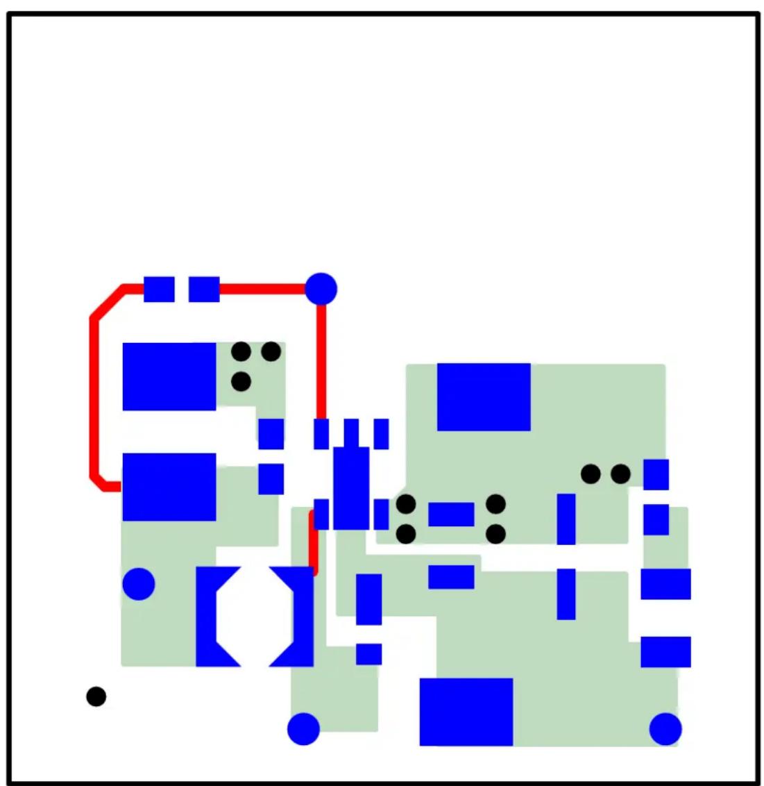
- Board – Top Layer
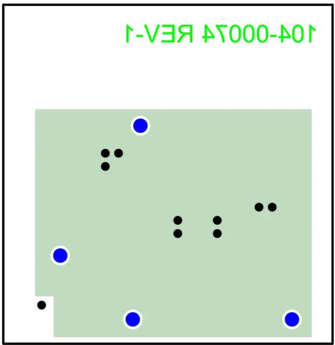
- Board – Bottom Layer
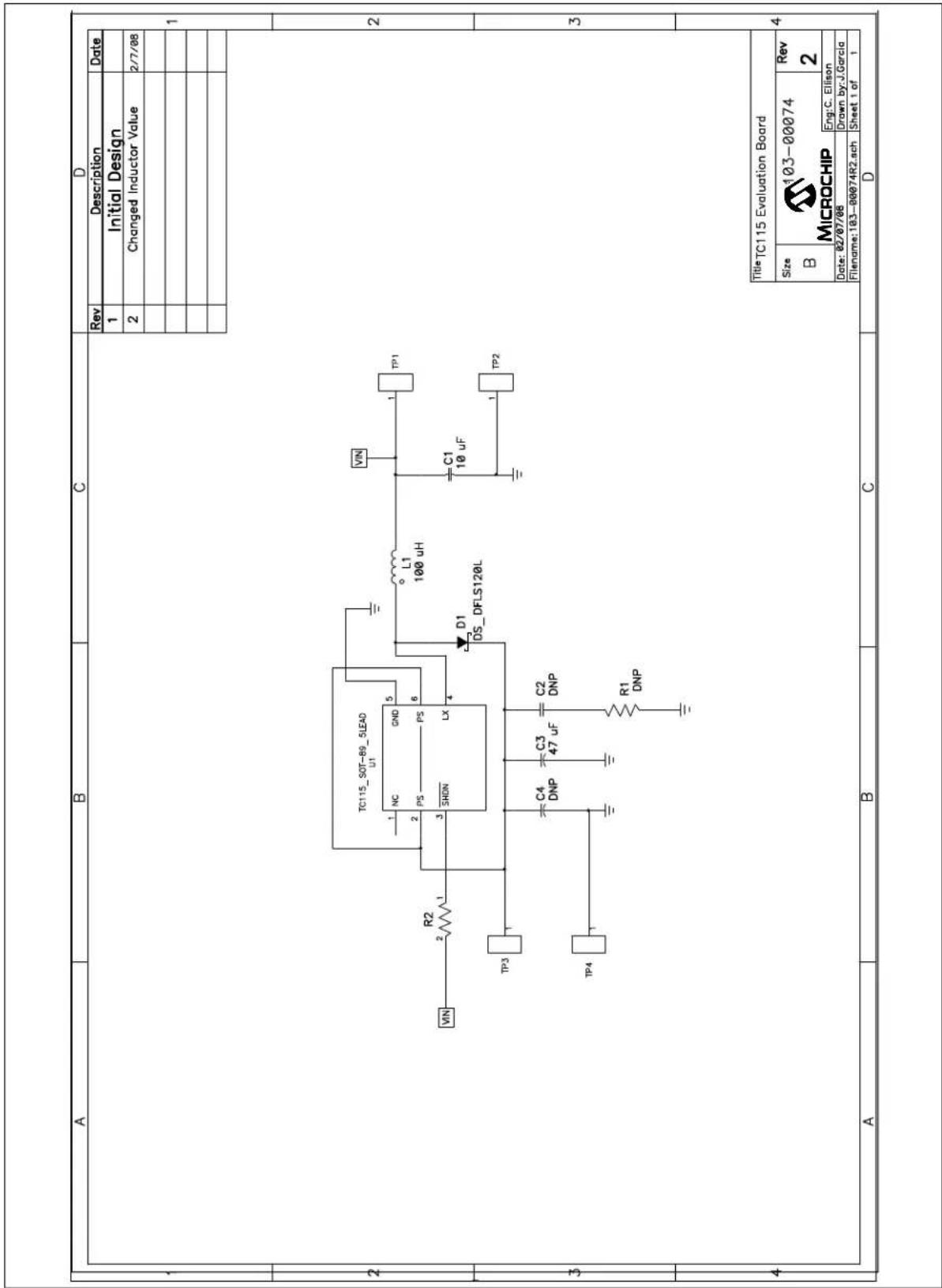
A.2 BOARD SCHEMATIC
other
The image contains an electronic circuit schematic with labeled components and pin numbers. The diagram includes: - Pin 1: TC115_SOT-69_5LEAD - Pin 2: TC115_SOT-69_5LEAD - Pin 3: TC115_SOT-69_5LEAD - Pin 4: TC115_SOT-69_5LEAD - Pin 5: TC115_SOT-69_5LEAD - Pin 6: TC115_SOT-69_5LEAD - Pin 7: TC115_SOT-69_5LEAD - Pin 8: TC115_SOT-69_5LEAD - Pin 9: TC115_SOT-69_5LEAD - Pin 10: TC115_SOT-69_5LEAD - Pin 11: TC115_SOT-69_5LEAD - Pin 12: TC115_SOT-69_5LEAD - Pin 13: TC115_SOT-69_5LEAD - Pin 14: TC115_SOT-69_5LEAD - Pin 15: TC115_SOT-69_5LEAD - Pin 16: TC115_SOT-69_5LEAD - Pin 17: TC115_SOT-69_5LEAD - Pin 18: TC115_SOT-69_5LEAD - Pin 19: TC115_SOT-69_5LEAD - Pin 20: TC115_SOT-69_5LEAD - Pin 21: TC115_SOT-69_5LEAD - Pin 22: TC115_SOT-69_5LEAD - Pin 23: TC115_SOT-69_5LEAD - Pin 24: TC115_SOT-69_5LEAD - Pin 25: TC115_SOT-69_5LEAD - Pin 26: TC115_SOT-69_5LEAD - Pin 27: TC115_SOT-69_5LEAD - Pin 28: TC115_SOT-69_5LEAD - Pin 29: TC115_SOT-69_5LEAD - Pin 30: TC115_SOT-69_5LEAD - Pin 31: TC115_SOT-69_5LEAD - Pin 32: TC115_SOT-69_5LEAD - Pin 33: TC115_SOT-69_5LEAD - Pin 34: TC115_SOT-69_5LEAD - Pin 35: TC115_SOT-69_5LEAD - Pin 36: TC115_SOT-69_5LEAD - Pin 37: TC115_SOT-69_5LEAD - Pin 38: TC115_SOT-69_5LEAD - Pin 39: TC115_SOT-69_5LEAD - Pin 40: TC115_SOT-69_5LEAD - Pin 41: TC115_SOT-69_5LEAD - Pin 42: TC115_SOT-69_5LEAD - Pin 43: TC115_SOT-69_5LEAD - Pin 44: TC115_SOT-69_5LEAD - Pin 45: TC115_SOT-69_5LEAD - Pin 46: TC115_SOT-69_5LEAD - Pin 47: TC115_SOT-69_5LEAD - Pin 48: TC115_SOT-69_5LEAD - Pin 49: TC115_SOT-69_5LEAD - Pin 50: TC115_SOT-69_5LEAD - Pin 51: TC115_SOT-69_5LEAD - Pin 52: TC115_SOT-69_5LEAD - Pin 53: TC115_SOT-69_5LEAD - Pin 54: TC115_SOT-69_5LEAD - Pin 55: TC115_SOT-69_5LEAD - Pin 56: TC115_SOT-69_5LEAD - Pin 57: TC115_SOT-69_5LEAD - Pin 58: TC115_SOT-69_5LEAD - Pin 59: TC115_SOT-69_5LEAD - Pin 60: TC115_SOT-69_5LEAD - Pin 61: TC115_SOT-69_5LEAD - Pin 62: TC115_SOT-69_5LEAD - Pin 63: TC115_SOT-69_5LEAD - Pin 64: TC115_SOT-69_5LEAD - Pin 65: TC115_SOT-69_5LEAD - Pin 66: TC115_SOT-69_5LEAD - Pin 67: TC115_SOT-69_5LEAD - Pin 68: TC115_SOT-69_5LEAD - Pin 69: TC115_SOT-69_5LEAD - Pin 70: TC115_SOT-69_5LEAD - Pin 71: TC115_SOT-69_5LEAD - Pin 72: TC115_SOT-69_5LEAD - Pin 73: TC115_SOT-69_5LEAD - Pin 74: TC115_SOT-69_5LEAD - Pin 75: TC115_SOT-69_5LEAD - Pin 76: TC115_SOT-69_5LEAD - Pin 77: TC115_SOT-69_5LEAD - Pin 78: TC115_SOT-69_5LEAD - Pin 79: TC115_SOT-69_5LEAD - Pin 80: TC115_SOT-69_5LEAD - Pin 81: TC115_SOT-69_5LEAD - Pin 82: TC115_SOT-69_5LEAD - Pin 83: TC115_SOT-69_5LEAD - Pin 84: TC115_SOT-69_5LEAD - Pin 85: TC115_SOT-69_5LEAD - Pin 86: TC115_SOT-69_5LEAD - Pin 87: TC115_SOT-69_5LEAD - Pin 88: TC115_SOT-69_5LEAD - Pin 89: TC115_SOT-69_5LEAD - Pin 90: TC115_SOT-69_5LEAD - Pin 91: TC115_SOT-69_5LEAD - Pin 92: TC115_SOT-69_5LEAD - Pin 93: TC115_SOT-69_5LEAD - Pin 94: TC115_SOT-69_5LEAD Pinout values are not explicitly provided in the image. The chart is designed to create a schematic representation of a microchip or microchip design tool. The title is 'TitleTCI' with the following table below it is clearly written in the image.A.3 BOARD - TOP OVERLAY

text_image
® MICROCHIP TC115 EVALUATION BOARD 102-00074 GND GND VIN + VOUTA.4 BOARD - TOP LAYER
natural_image
Abstract geometric pattern with blue and green blocks, red lines, and black dots (no text or symbols)A.5 BOARD - BOTTOM LAYER
scatter
| Point | X | Y | |-------|-------|-------| | 1 | 0.5 | 0.8 | | 2 | 0.6 | 0.7 | | 3 | 0.7 | 0.9 | | 4 | 0.8 | 0.6 | | 5 | 0.9 | 0.5 | | 6 | 1.0 | 0.7 | | 7 | 1.1 | 0.6 | | 8 | 1.2 | 0.8 | | 9 | 1.3 | 0.5 | | 10 | 1.4 | 0.7 | | 11 | 1.5 | 0.6 | | 12 | 1.6 | 0.8 | | 13 | 1.7 | 0.5 | | 14 | 1.8 | 0.7 | | 15 | 1.9 | 0.6 | | 16 | 2.0 | 0.8 | | 17 | 2.1 | 0.5 | | 18 | 2.2 | 0.7 | | 19 | 2.3 | 0.6 | | 20 | 2.4 | 0.8 | | 21 | 2.5 | 0.5 | | 22 | 2.6 | 0.7 | | 23 | 2.7 | 0.6 | | 24 | 2.8 | 0.8 | | 25 | 2.9 | 0.5 | | 26 | 3.0 | 0.7 | | 27 | 3.1 | 0.6 | | 28 | 3.2 | 0.8 | | 29 | 3.3 | 0.5 | | 30 | 3.4 | 0.7 | | 31 | 3.5 | 0.6 | | 32 | 3.6 | 0.8 | | 33 | 3.7 | 0.5 | | 34 | 3.8 | 0.7 | | 35 | 3.9 | 0.6 | | 36 | 4.0 | 0.8 | | 37 | 4.1 | 0.5 | | 38 | 4.2 | 0.7 | | 39 | 4.3 | 0.6 | | 40 | 4.4 | 0.8 | | 41 | 4.5 | 0.5 | | 42 | 4.6 | 0.7 | | 43 | 4.7 | 0.6 | | 44 | 4.8 | 0.8 | | 45 | 4.9 | 0.5 | | 46 | 5.0 | 0.7 | | 47 | 5.1 | 0.6 | | 48 | 5.2 | 0.8 | | 49 | 5.3 | 0.5 | | 50 | 5.4 | 0.7 | | 51 | 5.5 | 0.6 | | 52 | 5.6 | 0.8 | | 53 | 5.7 | 0.5 | | 54 | 5.8 | 0.7 | | 55 | 5.9 | 0.6 | | 56 | 6.0 | 0.8 | | 57 | 6.1 | 0.5 | | 58 | 6.2 | 0.7 | | 59 | 6.3 | 0.6 | | 60 | 6.4 | 0.8 | | 61 | 6.5 | 0.5 | | 62 | 6.6 | 0.7 | | 63 | 6.7 | 0.6 | | 64 | 6.8 | 0.8 | | 65 | 6.9 | 0.5 | | 66 | 7.0 | 0.7 | | 67 | 7.1 | 0.6 | | 68 | 7.2 | 0.8 | | 69 | 7.3 | 0.5 | | 70 | 7.4 | 0.7 | | 71 | 7.5 | 0.6 | | 72 | 7.6 | 0.8 | | 73 | 7.7 | 0.5 | | 74 | 7.8 | 0.7 | | 75 | 7.9 | 0.6 | | | | | The chart displays a scatter plot with two data series (black and blue dots) plotted against an unlabeled coordinate system (X, Y). The title of the chart is '1V3A' and 'EVA-1'. The data points are labeled as '1V3A'.NOTES:
Appendix B. Bill of Materials (BOM)
TABLE B-1: BILL OF MATERIALS (BOM)
| Qty. | Reference Description | Mfgr. Part Number | ||
| 1 C1 | 0 μF, X5R Ceramic, 6 | 3V 0805 Panasonic | ® | ECJ-CV50J106M |
| - C2 | Do Not Populate — | — | ||
| 1 C3 | 47 μF, Electrolytic Capacitator, 6.3V Nichicon | UWT0J470MCL1GB | ||
| - C4 | Do Not Populate — | — | ||
| 1 D1 | A, 20V Shottky Diode | Diodes Inc. | DFLS120L | |
| 1 L1 | 100 | μH, Inductor, SD25 Coiltronics ® | SD25-101-R | |
| 1 PCB | RoHS Compliant Bare PCB, TC115 PFM/PWM Boost Evaluation Board | — | 104-00074 | |
| - R1 | Do Not Populate — | — | ||
| 1 R2 | 475K, 1/8W,1%, Chip Resistor, 0805 Rohm | MCR10EZHF4753 | ||
| 4 TP1 | TP2, TP3, TP4 Test | Point Keystone Electronics ® | 5016 | |
| 1 | U1 | TC115 Step-up dc-dc Converter | Microchip Technology Inc. | TC115301EMTTR |
WORLDWIDE SALES AND SERVICE
AMERICAS
Corporate Office
2355 West Chandler Blvd.
Chandler, AZ 85224-6199
Tel: 480-792-7200
Fax: 480-792-7277
Technical Support:
http://support.microchip.com
Web Address:
www.microchip.com
Atlanta
Duluth, GA
Tel: 678-957-9614
Fax: 678-957-1455
Boston
Westborough, MA
Tel: 774-760-0087
Fax: 774-760-0088
Chicago
Itasca, IL
Tel: 630-285-0071
Fax: 630-285-0075
Dallas
Addison, TX
Tel: 972-818-7423
Fax: 972-818-2924
Detroit
Farmington Hills, MI
Tel: 248-538-2250
Fax: 248-538-2260
Kokomo
Kokomo, IN
Tel: 765-864-8360
Fax: 765-864-8387
Los Angeles
Mission Viejo, CA
Tel: 949-462-9523
Fax: 949-462-9608
Santa Clara
Santa Clara, CA
Tel: 408-961-6444
Fax: 408-961-6445
Toronto
Mississauga, Ontario,
Canada
Tel: 905-673-0699
Fax: 905-673-6509
ASIA/PACIFIC
Asia Pacific Office
Suites 3707-14, 37th Floor
Tower 6, The Gateway
Harbour City, Kowloon
Hong Kong
Tel: 852-2401-1200
Fax: 852-2401-3431
Australia - Sydney
Tel: 61-2-9868-6733
Fax: 61-2-9868-6755
China - Beijing
Tel: 86-10-8528-2100
Fax: 86-10-8528-2104
China - Chengdu
Tel: 86-28-8665-5511
Fax: 86-28-8665-7889
China - Hong Kong SAR
Tel: 852-2401-1200
Fax: 852-2401-3431
China - Nanjing
Tel: 86-25-8473-2460
Fax: 86-25-8473-2470
China - Qingdao
Tel: 86-532-8502-7355
Fax: 86-532-8502-7205
China - Shanghai
Tel: 86-21-5407-5533
Fax: 86-21-5407-5066
China - Shenyang
Tel: 86-24-2334-2829
Fax: 86-24-2334-2393
China - Shenzhen
Tel: 86-755-8203-2660
Fax: 86-755-8203-1760
China - Wuhan
Tel: 86-27-5980-5300
Fax: 86-27-5980-5118
China - Xiamen
Tel: 86-592-2388138
Fax: 86-592-2388130
China - Xian
Tel: 86-29-8833-7252
Fax: 86-29-8833-7256
China - Zhuhai
Tel: 86-756-3210040
Fax: 86-756-3210049
ASIA/PACIFIC
India - Bangalore
Tel: 91-80-4182-8400
Fax: 91-80-4182-8422
India - New Delhi
Tel: 91-11-4160-8631
Fax: 91-11-4160-8632
India - Pune
Tel: 91-20-2566-1512
Fax: 91-20-2566-1513
Japan - Yokohama
Tel: 81-45-471-6166
Fax: 81-45-471-6122
Korea - Daegu
Tel: 82-53-744-4301
Fax: 82-53-744-4302
Korea - Seoul
Tel: 82-2-554-7200
Fax: 82-2-558-5932 or
82-2-558-5934
Malaysia - Kuala Lumpur
Tel: 60-3-6201-9857
Fax: 60-3-6201-9859
Malaysia - Penang
Tel: 60-4-227-8870
Fax: 60-4-227-4068
Philippines - Manila
Tel: 63-2-634-9065
Fax: 63-2-634-9069
Singapore
Tel: 65-6334-8870
Fax: 65-6334-8850
Taiwan - Hsin Chu
Tel: 886-3-572-9526
Fax: 886-3-572-6459
Taiwan - Kaohsiung
Tel: 886-7-536-4818
Fax: 886-7-536-4803
Taiwan - Taipei
Tel: 886-2-2500-6610
Fax: 886-2-2508-0102
Thailand - Bangkok
Tel: 66-2-694-1351
Fax: 66-2-694-1350
EUROPE
Austria - Wels
Tel: 43-7242-2244-39
Fax: 43-7242-2244-393
Denmark - Copenhagen
Tel: 45-4450-2828
Fax: 45-4485-2829
France - Paris
Tel: 33-1-69-53-63-20
Fax: 33-1-69-30-90-79
Germany - Munich
Tel: 49-89-627-144-0
Fax: 49-89-627-144-44
Italy - Milan
Tel: 39-0331-742611
Fax: 39-0331-466781
Netherlands - Drunen
Tel: 31-416-690399
Fax: 31-416-690340
Spain - Madrid
Tel: 34-91-708-08-90
Fax: 34-91-708-08-91
UK - Wokingham
Tel: 44-118-921-5869
Fax: 44-118-921-5820