MCP19111 - Electronic component Microchip - Free user manual and instructions
Find the device manual for free MCP19111 Microchip in PDF.

User questions about MCP19111 Microchip
0 question about this device. Answer the ones you know or ask your own.
Ask a new question about this device
Download the instructions for your Electronic component in PDF format for free! Find your manual MCP19111 - Microchip and take your electronic device back in hand. On this page are published all the documents necessary for the use of your device. MCP19111 by Microchip.
USER MANUAL MCP19111 Microchip
Note the following details of the code protection feature on Microchip devices:
• Microchip products meet the specification contained in their particular Microchip Data Sheet.
- Microchip believes that its family of products is one of the most secure families of its kind on the market today, when used in the intended manner and under normal conditions.
- There are dishonest and possibly illegal methods used to breach the code protection feature. All of these methods, to our knowledge, require using the Microchip products in a manner outside the operating specifications contained in Microchip's Data Sheets. Most likely, the person doing so is engaged in theft of intellectual property.
• Microchip is willing to work with the customer who is concerned about the integrity of their code.
- Neither Microchip nor any other semiconductor manufacturer can guarantee the security of their code. Code protection does not mean that we are guaranteeing the product as "unbreakable."
Code protection is constantly evolving. We at Microchip are committed to continuously improving the code protection features of our products. Attempts to break Microchip's code protection feature may be a violation of the Digital Millennium Copyright Act. If such acts allow unauthorized access to your software or other copyrighted work, you may have a right to sue for relief under that Act.
Information contained in this publication regarding device applications and the like is provided only for your convenience and may be superseded by updates. It is your responsibility to ensure that your application meets with your specifications. MICROCHIP MAKES NO REPRESENTATIONS OR WARRANTIES OF ANY KIND WHETHER EXPRESS OR IMPLIED, WRITTEN OR ORAL, STATUTORY OR OTHERWISE, RELATED TO THE INFORMATION, INCLUDING BUT NOT LIMITED TO ITS CONDITION, QUALITY, PERFORMANCE, MERCHANTABILITY OR FITNESS FOR PURPOSE. Microchip disclaims all liability arising from this information and its use. Use of Microchip devices in life support and/or safety applications is entirely at the buyer's risk, and the buyer agrees to defend, indemnify and hold harmless Microchip from any and all damages, claims, suits, or expenses resulting from such use. No licenses are conveyed, implicitly or otherwise, under any Microchip intellectual property rights.
Trademarks
The Microchip name and logo, the Microchip logo, dsPIC, FlashFlex, flexPWR, JukeBlox, KEELOQ, KEELOQ logo, Kleer, LANCheck, MediaLB, MOST, MOST logo, MPLAB, OptoLyzer, PIC, PICSTART, PIC ^32 logo, RightTouch, SpyNIC, SST, SST Logo, SuperFlash and UNI/O are registered trademarks of Microchip Technology Incorporated in the U.S.A. and other countries.
The Embedded Control Solutions Company and mTouch are registered trademarks of Microchip Technology Incorporated in the U.S.A.
Analog-for-the-Digital Age, BodyCom, chipKIT, chipKIT logo, CodeGuard, dsPICDEM, dsPICDEM.net, ECAN, In-Circuit Serial Programming, ICSP, Inter-Chip Connectivity, KleerNet, KleerNet logo, MiWi, MPASM, MPF, MPLAB Certified logo, MPLIB, MPLINK, MultiTRAK, NetDetach, Omniscient Code Generation, PICDEM, PICDEM.net, PICkit, PICtail, RightTouch logo, REAL ICE, SQI, Serial Quad I/O, Total Endurance, TSHARC, USBCheck, VariSense, ViewSpan, WiperLock, Wireless DNA, and ZENA are trademarks of Microchip Technology Incorporated in the U.S.A. and other countries.
SQTP is a service mark of Microchip Technology Incorporated in the U.S.A.
Silicon Storage Technology is a registered trademark of Microchip Technology Inc. in other countries.
GestIC is a registered trademarks of Microchip Technology Germany II GmbH & Co. KG, a subsidiary of Microchip Technology Inc., in other countries.
All other trademarks mentioned herein are property of their respective companies.
© 2014-2015, Microchip Technology Incorporated, Printed in the U.S.A., All Rights Reserved.
Microchip received ISO/TS-16949:2009 certification for its worldwide headquarters, design and wafer fabrication facilities in Chandler and Tempe, Arizona; Gresham, Oregon and design centers in California and India. The Company's quality system processes and procedures are for its PIC® MCUs and dsPIC® DSCs, KEELoo® code hopping devices, Serial EEPROMs, microperipherals, nonvolatile memory and analog products. In addition, Microchip's quality system for the design and manufacture of development systems is ISO 9001:2000 certified.
Object of Declaration: MCP19111 Battery Charger Evaluation Board
EU Declaration of Conformity
Manufacturer:
Microchip Technology Inc.
2355 W. Chandler Blvd.
Chandler, Arizona, 85224-6199
USA
This declaration of conformity is issued by the manufacturer.
The development/evaluation tool is designed to be used for research and development in a laboratory environment. This development/evaluation tool is not a Finished Appliance, nor is it intended for incorporation into Finished Appliances that are made commercially available as single functional units to end users under EU EMC Directive 2004/108/EC and as supported by the European Commission's Guide for the EMC Directive 2004/108/EC (8 ^th February 2010).
This development/evaluation tool complies with EU RoHS2 Directive 2011/65/EU.
This development/evaluation tool, when incorporating wireless and radio-telecom functionality, is in compliance with the essential requirement and other relevant provisions of the R&TTE Directive 1999/5/EC and the FCC rules as stated in the declaration of conformity provided in the module datasheet and the module product page available at www.microchip.com.
For information regarding the exclusive, limited warranties applicable to Microchip products, please see Microchip's standard terms and conditions of sale, which are printed on our sales documentation and available at www.microchip.com.
Signed for and on behalf of Microchip Technology Inc. at Chandler, Arizona, USA

text_image
Derek Carlson VP Development Tools
NOTES:
Table of Contents
Preface 7
Chapter 1. Product Overview
1.1 Introduction ...... 11
1.2 Short Overview: MCP19111 Enhanced Power Analog Controller .... 11
1.3 What is the MCP19111 Battery Charger Evaluation Board? 11
1.4 MCP19111 Battery Charger Evaluation Board Kit Contents 12
Chapter 2. Installation and Operation
2.1 Introduction ...... 13
2.1.1 MCP19111 Battery Charger Evaluation Board Features 13
2.2 Getting Started 13
2.2.1 Configuration Requirements 13
2.2.2 Installing the MCP19111 Battery Charger Evaluation Board GUI 14
Chapter 3. Graphical User Interface
3.1 Running the MCP19111 Battery Charger Evaluation Board 17
3.1.1 Setting up the GUI and the Board 17
3.1.2 Charge Configuration 18
3.1.2.1 Configuration Tab – Other Configuration Parameters ..... 19
3.1.3 Running a Charge Profile 20
3.1.4 Battery Chemistry Charge Profiles 21
3.2 Programming the MCP19111 Battery Charger Evaluation Board 26
3.3 Calibrating the MCP19111 Battery Charger Evaluation Board 28
Appendix A. Schematic and Layouts
A.1 Introduction 33
A.2 Board – Schematic 34
A.3 Board - Schematic (Continued) 35
A.4 Board – Top Silk 36
A.5 Board – Top Copper and Silk 37
A.6 Board – Top Copper 38
A.7 Board - Mid Layer 1 39
A.8 Board - Mid Layer 2 40
A.9 Board – Bottom Copper 41
A.10 Board – Bottom Copper and Silk 42
A.11 Board – Bottom Silk 43
Appendix B. Bill of Materials (BOM)...... 45
Appendix C. Charge Profile Block Diagrams
C.1 Introduction 47
Worldwide Sales and Service 64
NOTES:
Preface
NOTICE TO CUSTOMERS
All documentation becomes dated, and this manual is no exception. Microchip tools and documentation are constantly evolving to meet customer needs, so some actual dialogs and/or tool descriptions may differ from those in this document. Please refer to our web site (www.microchip.com) to obtain the latest documentation available.
Documents are identified with a "DS" number. This number is located on the bottom of each page, in front of the page number. The numbering convention for the DS number is "DSXXXXXXXXA", where "XXXXXXXXX" is the document number and "A" is the revision level of the document.
For the most up-to-date information on development tools, see the MPLAB ^® IDE on-line help. Select the Help menu, and then Topics to open a list of available on-line help files.
INTRODUCTION
This chapter contains general information that will be useful to know before using the MCP19111 Battery Charger Evaluation Board. Items discussed in this chapter include:
- Document Layout
- Conventions Used in this Guide
- Warranty Registration
• Recommended Reading
• The Microchip Web Site - Development Systems Customer Change Notification Service
- Customer Support
• Document Revision History
DOCUMENT LAYOUT
This document describes how to use the MCP19111 Battery Charger Evaluation Board as a development tool to emulate and debug firmware on a target board. The manual layout is as follows:
- Chapter 1. “Product Overview” – Contains important information on the MCP19111 Battery Charger Evaluation Board
- Chapter 2. "Installation and Operation" – Covers the initial setup and operation of the MCP19111 Battery Charger Evaluation Board
- Chapter 3. “Graphical User Interface” – Provides detailed information on the Graphical User Interface (GUI)
- Appendix A. “Schematic and Layouts” – Shows the schematic and board layouts for the MCP19111 Battery Charger Evaluation Board
- Appendix B. "Bill of Materials (BOM)" – Lists the parts used to build the MCP19111 Battery Charger Evaluation Board
- Appendix C. “Charge Profile Block Diagrams” – Includes the block diagrams that show the flow of logic that enables the MCP19111 to control the charge cycle for efficient battery charging
CONVENTIONS USED IN THIS GUIDE
This manual uses the following documentation conventions:
DOCUMENTATION CONVENTIONS
| Description Represents Examples | ||
| Arial font: | ||
| Italic characters Referenced books | mPLAB | ^ IDE User's Guide |
| Emphasized text ...is the only compiler... | ||
| Initial caps A window the Output | ut window | |
| A dialog the Settings dialog | ||
| A menu selection select Enable Programmer | ||
| Quotes A field name in a window or dialog | "Save project before build" | |
| Underlined, italic text with right angle bracket | A menu path File>Save | —— |
| Bold characters A dialog button | Click OK | |
| A tab | Click the Power tab | |
| N'Rnnnn | A number in verilog format, where N is the total number of digits, R is the radix and n is a digit. | 4'b0010, 2'hF1 |
| Text in angle brackets < > | A key on the keyboard | Press,, |
| Courier New font: | ||
| Plain Courier New | Sample source code | #define START |
| Filenames | autoexec.bat | |
| File paths c:\mccl8\h | ||
| Keywords | _asm, _endasm, static | |
| Command-line options | -Opa+, -Opa- | |
| Bit values | 0, 1 | |
| Constants | 0xFF, 'A' | |
| Italic Courier New | A variable argument | file.o, where file can be any valid filename |
| Square brackets [] | Optional arguments | mccl8 [options] file [options] |
| Curly brackets and pipe character: { | } | Choice of mutually exclusive arguments; an OR selection | errorlevel {0|1} |
| Ellipses... | Replaces repeated text | var_name [, var_name...] |
| Represents code supplied by user | void main (void) { ... } | |
WARRANTY REGISTRATION
Please complete the enclosed Warranty Registration Card and mail it promptly. Sending in the Warranty Registration Card entitles users to receive new product updates. Interim software releases are available at the Microchip web site.
RECOMMENDED READING
This user's guide describes how to use MCP19111 Battery Charger Evaluation Board. Other useful documents are listed below. The following Microchip documents are available and recommended as supplemental reference resources.
MCP19110/11 Data Sheet (DS20002331)
This data sheet describes the operation and features of the MCP19110/11 devices which are digitally-enhanced power analog controllers with an integrated synchronous driver.
MCP19110/11/18/19 – Buck Power Supply Graphical User Interface User's Guide (DS50002113)
This user's guide describes the operation and features of the MCP19110/11/18/19 Buck Power Supply GUI plug-in controller.
Microchip provides online support via our web site at www.microchip.com. This web site is used as a means to make files and information easily available to customers. Accessible by using your favorite Internet browser, the web site contains the following information:
- Product Support – Data sheets and errata, application notes and sample programs, design resources, user's guides and hardware support documents, latest software releases and archived software
- General Technical Support – Frequently Asked Questions (FAQs), technical support requests, online discussion groups, Microchip consultant program member listing
- Business of Microchip – Product selector and ordering guides, latest Microchip press releases, listing of seminars and events, listings of Microchip sales offices, distributors and factory representatives
DEVELOPMENT SYSTEMS CUSTOMER CHANGE NOTIFICATION SERVICE
Microchip's customer notification service helps keep customers current on Microchip products. Subscribers will receive e-mail notification whenever there are changes, updates, revisions or errata related to a specified product family or development tool of interest.
To register, access the Microchip web site at www.microchip.com, click on Customer Change Notification and follow the registration instructions.
The Development Systems product group categories are:
- Compilers – The latest information on Microchip C compilers, assemblers, linkers and other language tools. These include all MPLAB ^ C compilers; all MPLAB assemblers (including MPASM ^TM assembler); all MPLAB linkers (including MPLINK ^TM object linker); and all MPLAB librarians (including MPLIB ^TM object librarian).
- Emulators – The latest information on Microchip in-circuit emulators. This includes the MPLAB REAL ICE™ and MPLAB ICE 2000 in-circuit emulators.
- In-Circuit Debuggers – The latest information on the Microchip in-circuit debuggers. This includes MPLAB ICD 3 in-circuit debuggers and PICkit™ 3 debug express.
- MPLAB IDE – The latest information on Microchip MPLAB IDE, the Windows® Integrated Development Environment for development systems tools. This list is focused on the MPLAB IDE, MPLAB IDE Project Manager, MPLAB Editor and MPLAB SIM simulator, as well as general editing and debugging features.
- Programmers – The latest information on Microchip programmers. These include production programmers, such as MPLAB REAL ICE in-circuit emulator, MPLAB ICD 3 in-circuit debugger and MPLAB PM3 device programmers. Also included are non-production development programmers, such as PICSTART® Plus and PICkit 2 and 3.
CUSTOMER SUPPORT
Users of Microchip products can receive assistance through several channels:
• Distributor or Representative
- Local Sales Office
• Field Application Engineer (FAE)
- Technical Support
Customers should contact their distributor, representative or field application engineer (FAE) for support. Local sales offices are also available to help customers. A listing of sales offices and locations is included in the back of this document.
Technical support is available through the web site at:
http://www.microchip.com/support.
DOCUMENT REVISION HISTORY
Revision B (June 2015)
- Updated Appendix A. "Schematic and Layouts" to show layout Revision 2 for this board.
- Updated Appendix C. "Charge Profile Block Diagrams".
Revision A (October 2014)
- Initial Release of this Document.
Chapter 1. Product Overview
1.1 INTRODUCTION
This chapter provides an overview of the MCP19111 Battery Charger Evaluation Board and covers the following topics:
- Short Overview: MCP19111 Enhanced Power Analog Controller
• What is the MCP19111 Battery Charger Evaluation Board?
• MCP19111 Battery Charger Evaluation Board Kit Contents
1.2 SHORT OVERVIEW: MCP19111 ENHANCED POWER ANALOG CONTROLLER
The MCP19111 device is a highly integrated, mixed-signal, analog Pulse-Width Modulation (PWM) Current mode controller with an integrated microcontroller core for synchronous DC/DC step-down applications. Since the MCP19111 uses traditional analog control circuitry to regulate the output of the DC/DC converter, the integration of the PIC ^® microcontroller mid-range core is used to provide complete customization of the device operating parameters, start-up and shutdown profiles, protection levels and Fault handling procedures.
1.3 WHAT IS THE MCP19111 BATTERY CHARGER EVALUATION BOARD?
The MCP19111 Battery Charger Evaluation Board is intended to demonstrate how the MCP19111 device operates in a buck topology for the purpose of charging batteries of various chemistries. It is configured to regulate the amount of charge current, and the type of charging, while simultaneously reading the state of the battery to change between operation modes for optimized charge profiles. Nearly all operational charge parameters are programmable by utilizing the integrated PIC microcontroller core.
The board comes preprogrammed with firmware designed to operate with the Graphical User Interface (GUI). MPLAB ^® X Integrated Development Environment (IDE) software can be used to download user-defined firmware, thus tailoring it to the user's specific application. The evaluation board contains headers for In-Circuit Serial Programming ^™ (ICSP ^™ ), as well as I ^2 C ^™ communication. The MCP19111 Battery Charger Evaluation Board firmware implements an SSP module process derived from the I ^2 C specification to allow the MCP19111 to communicate with the GUI via a PICkit ^™ Serial Analyzer. MPLAB X IDE, MPLAB XC8 Compiler toolchain, the MCP19111 Battery Charger Evaluation Board GUI and the MCP19111 Battery Charger Evaluation Board firmware are available for download from the Microchip web site. See Chapter 3. “Graphical User Interface” for details.
1.4 MCP19111 BATTERY CHARGER EVALUATION BOARD KIT CONTENTS
The MCP19111 Battery Charger Evaluation Board kit includes the following items:
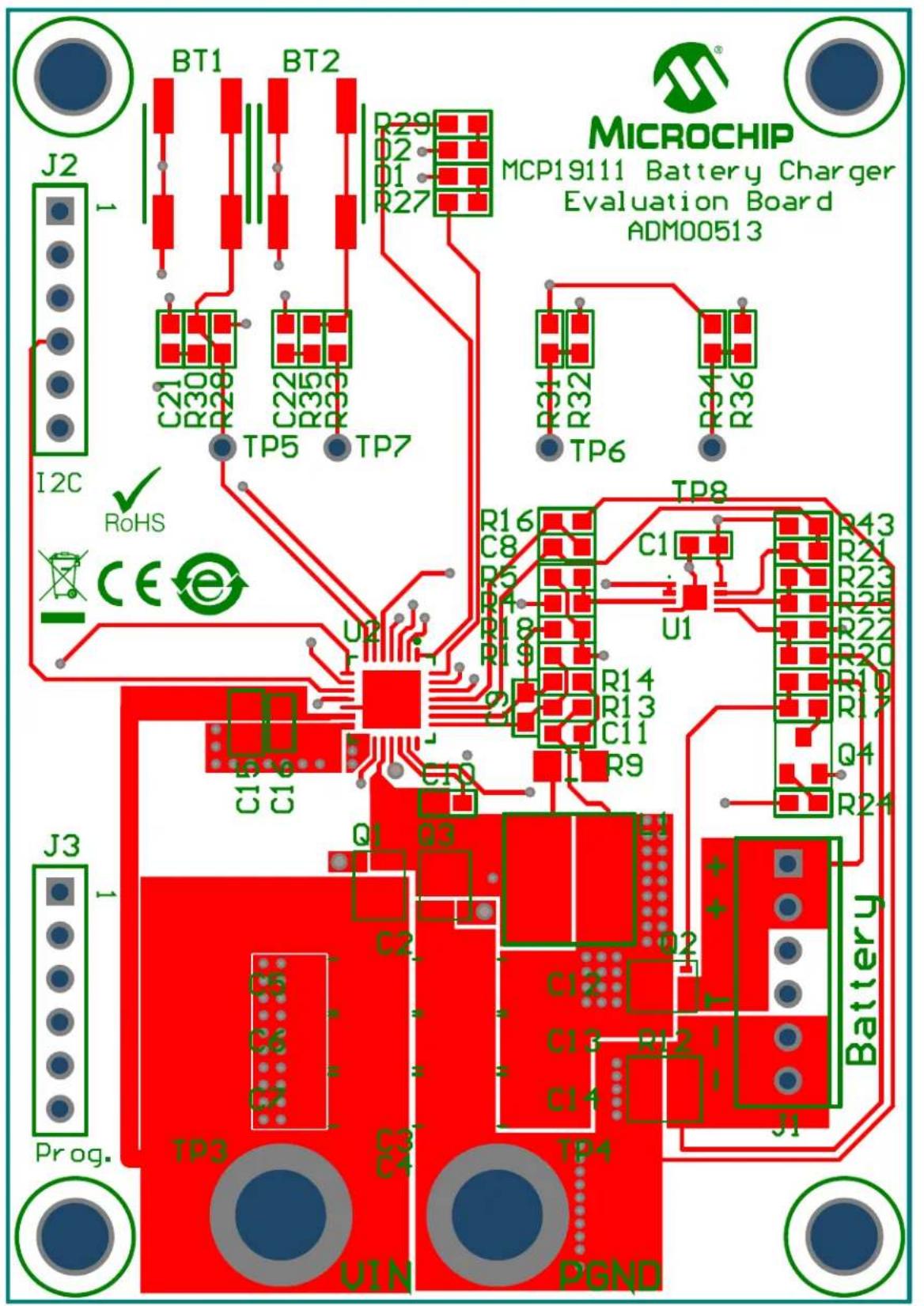
• MCP19111 Battery Charger Evaluation Board (ADM00513)
- Important Information Sheet

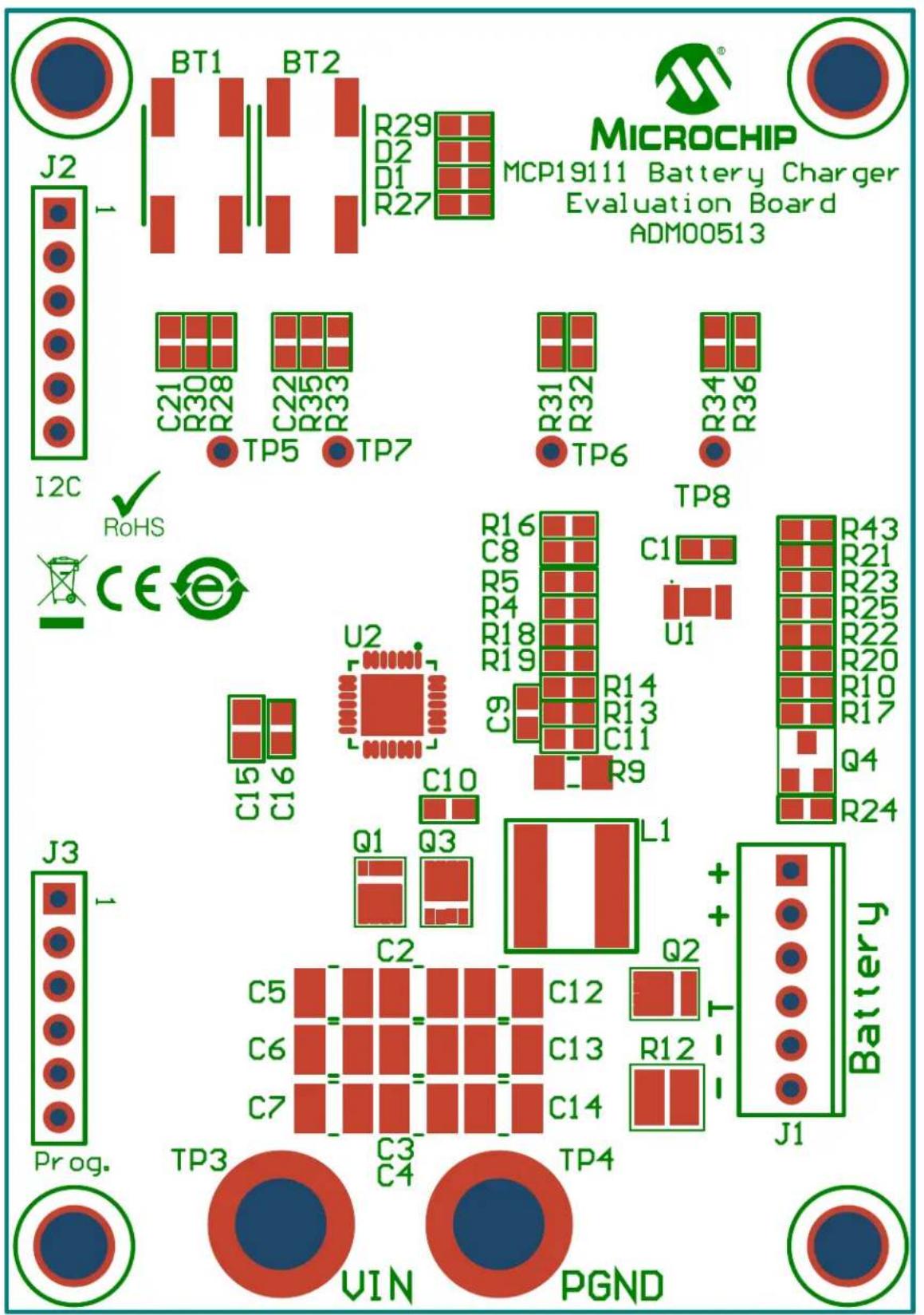
text_image
J2 BT1 BT2 R29 R02 R01 R27 MICROCHIP MCP19111 Battery Charger Evaluation Board ADM00513 C21 R30 R28 C22 R35 R33 TP5 TP7 R31 R32 TP6 R34 R36 TP8 CE U2 C16 CB R5 R18 R19 R14 R13 C11 7580 R9 U1 R43 R21 R23 R25 R22 R20 R10 R17 Q4 R24 J3 C15 C16 C10 Q1 Q3 C2 C5 C6 C7 TP3 C3 C4 TP4 UIN PGNDFIGURE 1-1: MCP19111 Battery Charger Evaluation Board.
Chapter 2. Installation and Operation
2.1 INTRODUCTION
2.1.1 MCP19111 Battery Charger Evaluation Board Features
The MCP19111 Battery Charger Evaluation Board is used to charge Nickel Metal-Hydride (NiMH) batteries of up to seven cells, Lithium-Ion (Li-Ion) batteries of up to four cells, Valve-Regulated Lead-Acid (VRLA) batteries of up to six cells and Lithium Iron Phosphate (LiFePO4) batteries of up to five cells. The board uses the MCP19111 digitally-enhanced PWM controller to generate the charge algorithms for the various battery types. The board can run in Rapid Charge Current mode for NiMH batteries, as well as Constant-Current/Constant-Voltage mode for Li-Ion batteries and LiFePO4. The MCP19111 Battery Charger Evaluation Board also has two charge configurations for VRLA batteries, which can be charged in both Rapid Charge and Constant-Current modes. The MCP19111 is limited by its input voltage range of 32V.
The MCP19111 Battery Charger Evaluation Board is used to evaluate Microchip's MCP19111 device in a buck power converter topology for a battery-charging application. The MCP19111 device works in conjunction with both current and voltage sense control loops to monitor and regulate the battery pack voltage or charge current. The battery charger board also provides several status and Fault indications for various states of the board. Moreover, the board detects the presence or the removal of a battery pack. The board has the capability to connect to both the PICkit™ 3 In-Circuit Debugger/Programmer for reprogramming and the PICkit Serial Analyzer to operate in conjunction with the GUI. Normally, the PICkit Serial Analyzer is used to configure the charge cycle and to change parameters.
The MCP19111 Battery Charger Evaluation Board is fully assembled, programmed and tested to evaluate and demonstrate the MCP19111 operating performance in a digitally-controlled, “smart battery-charging” application for various common battery chemistries.
2.2 GETTING STARTED
2.2.1 Configuration Requirements
The MCP19111 Battery Charger Evaluation Board GUI requires a computer with Microsoft® Windows® XP/7/8 operating system and a USB 2.0 port. To run the software, follow the steps described in this section.
To power-up and run the MCP19111 Battery Charger Evaluation Board with the GUI, the following are required:
• MCP19111 Battery Charger Evaluation Board
• MCP19111 Battery Charger Evaluation Board GUI
- PICkit Serial Analyzer
- Input Power Supply (capable of supplying enough current to support all charge cycles)
- Battery Pack
2.2.2 Installing the MCP19111 Battery Charger Evaluation Board GUI
Follow the steps below to download and install the MCP19111 Battery Charger Evaluation Board GUI:
- The MCP19111 Battery Charger Evaluation Board firmware and GUI archive can be downloaded from the Microchip web site at www.microchip.com/mcp19111.
- After downloading and unzipping the archive, open the GUI folder and locate the setup.exe file.
- Double-click the file. In the Application Install - Security Warning dialog box, press the Install button.

text_image
Application Install - Security Warning Publisher cannot be verified. Are you sure you want to install this application? Name: MCP19111BatteryChargerGUI From (Hover over the string below to see the full domain): C:\Users\c15492\Documents\Microchip Documents\MCP19111\MCP19111 Battery Charger\GU Publisher: Unknown Publisher Install Don't Install While applications can be useful, they can potentially harm your computer. If you do not trust the source, do not install this software. More Information...FIGURE 2-1: Installing the MCP19111 Battery Charger Evaluation Board GUI.
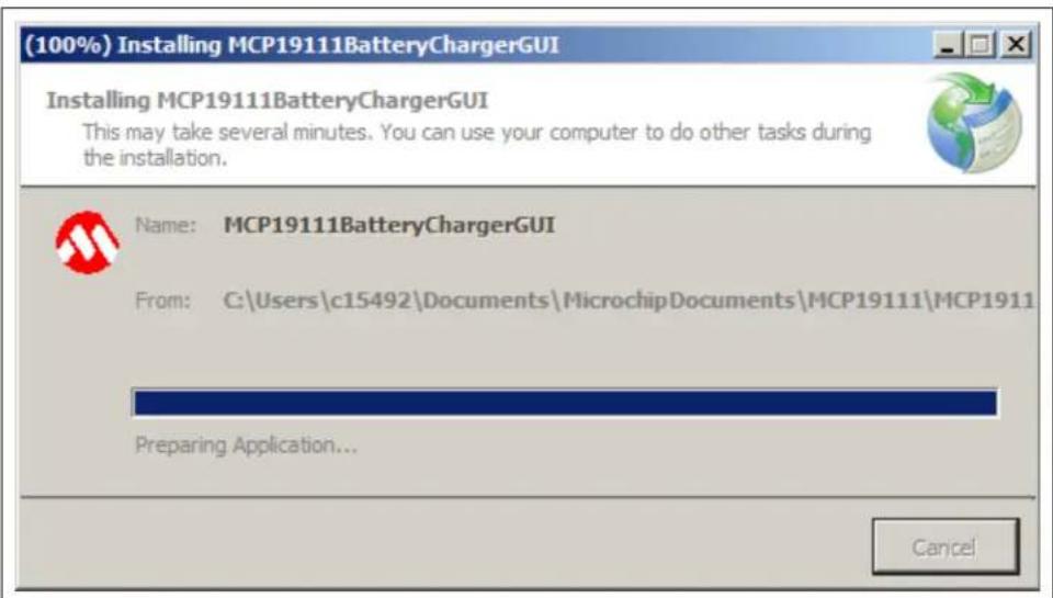
- The (100%) Installing MCP19111BatteryChargerGUI window showing the installation progress will appear briefly on the screen.
text_image
(100%) Installing MCP19111BatteryChargerGUI Installing MCP19111BatteryChargerGUI This may take several minutes. You can use your computer to do other tasks during the installation. Name: MCP19111BatteryChargerGUI From: C:\Users\c15492\Documents\MicrochipDocuments\MCP19111\MCP1911 Preparing Application... CancelFIGURE 2-2: The (100%) Installing MCP19111BatteryChargerGUI Window.
- Once the installation is complete, the GUI will be displayed on the screen.

text_image
MCP19111 Battery Charger GUI Profile | Configure | Calibrate | Pack Voltage: Charger Status: Pack Current: Pack Temperature: Input Voltage: Charge Time: Charger State: Not Connected Start Stop Save DataFIGURE 2-3: The MCP19111 Battery Charger Evaluation Board GUI.
NOTES:
Chapter 3. Graphical User Interface
3.1 RUNNING THE MCP19111 BATTERY CHARGER EVALUATION BOARD
3.1.1 Setting up the GUI and the Board
- Connect two banana-banana power cables from the power supply to V_IN and GND jacks on the MCP19111 Battery Charger Evaluation Board. The board should be powered within the range of approximately 13V-28V or V_IN > V_OUT + 2V . Different battery chemistries will not start operating until a certain input voltage has been reached. However, most types of batteries will charge with an input of 16V to the battery charger board.
- Connect a battery pack to the J1 header on the evaluation board. Take note of the type of battery, as well as the number of cells and amount of capacity (mAh). These details will become important when running specific charge profiles with the GUI. Ensure the battery is connected to the battery pack properly. The battery pack should have a secure cable to attach to J1 that correctly orients the positive (+) lead with Pins 1 and 2 of J1, and the negative (−) lead with Pins 5 and 6 of J1.
- Attach a PICkit™ serial device to J2 on the board and connect to the computer via USB. Ensure the PICkit device is powered and not in "busy" status.
- Make sure the MCP19111 Battery Charger Evaluation Board GUI is installed on the computer. Apply power to the board at a value of V_IN > V_OUT + 2V or 6V minimum and open the GUI.
3.1.2 Charge Configuration
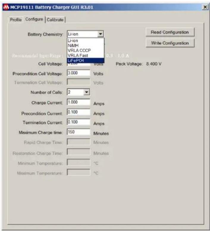
- Once the board is powered and calibrated, select a correct charge configuration based on the type of battery being charged, and other factors, such as the rate it needs to be charged at. All these parameters can be changed in the Configure tab of the GUI.
text_image
MCP19111 Battery Charger GUI R3.01 Profile Configure Calibrate Battery Chemistry: Li-ion Li-ion NiMH VRLA CCCP VRLA Fast Recommended Input Range : 0.3 - 1.0 A LiFePO4 Cell Voltage: 7.200 Volts Pack Voltage: 8.400 V Precondition Cell Voltage: 3.000 Volts Termination Cell Voltage: Volts Number of Cells: 2 Charge Current: 1.000 Amps Precondition Current: 0.100 Amps Termination Current: 0.100 Amps Maximum Charge time: 150 Minutes Rapid Charge Time: Minutes Restoration Charge Time: Minutes Minimum Temperature: °C Maximum Temperature: °CFIGURE 3-1: The GUI Configure Tab with Available Battery Chemistries.
- From the Battery Chemistry drop-down menu at the top of the Configure tab, the user can select the chemistry of the battery they intend to charge between Lithium ("Li-Ion"), "NiMH", "VRLA CCCP" (Constant-Current Constant Potential), "VRLA Fast" (Rapid Charge Current Mode) and Lithium Iron Phosphate (LiFePO4).
Note: The different types of battery chemistries require different charge profiles and selecting any of these lets the GUI provide a preset value for the various charge parameters. It also blocks off certain parameters that can be controlled by the user in order to ensure safe and efficient charging for each type of battery chemistry.
-
The current charge configuration that is set in the firmware of the board can be read into the GUI by selecting the Read Configuration button. If a board has not been configured with its current firmware, it will send an error message indicating it does not have a configuration and the user will be required to write one. Refer to the data sheets for the battery pack being used for proper charge parameters to enter into the GUI. When the user has entered the desired parameters into the charge profile, the Write Configuration button must be selected to write the profile into the firmware of the MCP19111.
-
If the battery pack has a thermistor, the user can select the "With Thermistor" check box to allow the MCP19111 to read temperature values, which are simultaneously displayed numerically, as well as on a real-time graph in the Profile tab, so the user can monitor the battery pack temperature.
3.1.2.1 CONFIGURATION TAB – OTHER CONFIGURATION PARAMETERS
TABLE 3-1: OTHER CONFIGURATION PARAMETERS
| Parameter Description | |
| Cell Voltage This parameter controls the rated voltage of each cell in the battery pack. | |
| Precondition Cell Voltage This parameter sets the voltage value at which the battery charger transitions from the Precondition Current mode to its Constant-Current mode. This transition is meant to protect the battery pack if the value is below the minimum value of the working voltage. | |
| Termination Cell Voltage This parameter controls the pack voltage value at which the battery charger ends the main charge phase and transitions to the Trickle Charge mode or turns off. This value is typically the maximum value of the specified working voltage range. | |
| Rapid Charge/Charge Current This parameter provides the current value applied to the battery pack by the charger during the main charging state. The charger implements either Rapid Charge mode or Charge Current mode, depending on the battery chemistry selected. | |
| Restoration/Precondition Current For deeply discharged batteries, a small amount of restoration current is necessary to bring the battery pack voltage to a level that is safe to implement Rapid Charge Current mode or Charge Current mode. This parameter controls the current value applied during this stage of charging. | |
| Trickle Charge Current After the battery reaches termination cell voltage, the sudden decrease in current will lead to a drop in the pack voltage. The battery charger applies a trickle charge current controlled by this parameter for an allotted period of time to regulate the voltage at which the main charge cycle terminated. | |
| Termination Current For Li-Ion and VRLA C CCP chemistries that end their charge cycle in Constant-Voltage mode, the termination current parameter controls the current value at which the battery charger will end the charge cycle. The battery charger will slowly ramp down the charge current to this value and then turn off. | |
| Number of Cells Enter the number of cells for the attached battery. The GUI uses this to calculate the termination voltage to charge the battery to. Each battery chemistry allows for certain ranges of cell arrangements. | |
| Rapid Charge Time | This parameter sets the maximum time period during which the battery charger will run in Rapid Charge mode. |
| Restoration Charge Time This parameter sets the maximum time period during which the battery charger will apply restoration current to the battery. | |
| Maximum Temperature | A protection feature for the battery that is only active when the “With Thermistor” check box is selected with a NiMH charge profile. The parameter sets the maximum temperature in degrees Celsius (°C) that the battery can reach before the battery charger shuts off completely. |
| Minimum Temperature | A protection feature for the battery that is only active when the “With Thermistor” check box is selected. The parameter sets the minimum temperature in degrees Celsius (°C) that the battery can fall down to before the battery charger shuts off completely. |
3.1.3 Running a Charge Profile
Once the user has ensured the battery charger board is powered, programmed, calibrated and configured properly, a charge profile can be defined. By selecting the Profile tab, the user can control running the charge profile and monitoring the charge status. At the top of the tab, the user can view the instantaneous values of the pack voltage, pack current, input voltage and state of the charger.
At all times, the user can see whether the battery pack is charging or not. The battery charger board will also give error states, such as Overtemperature (OT), Under Threshold Input Voltage (UT) or Over Threshold Input Voltage (OVT). The charger will say "Off" if the user attempts to run a charge, but the charger board is not currently running.
Note: The MCP19111 Battery Charger Evaluation Board is shipped already programmed and calibrated. Unless the user programs it themselves or adjusts the calibration data, the Charge Configuration is the only necessary user input.
When the battery is successfully charging, the Charger State will read different states based on the type of battery that is being charged. Examples of different charge states include "Precondition", "Constant-Current", "Constant-Voltage", "Rapid Charge", "Trickle" and "Off".
Enabling the charge can be toggled by selecting the Start and Stop buttons. The graphs on the lower half of the tab display real-time voltage and current, as well as a temperature profile if the "With Thermistor" check box was selected in the Configure tab. The GUI allows for the reporting of the various measured values in real time, so that the user can monitor if charge current and voltage are regulating correctly and safely. The charge current limitations are defined by the following values:
- Minimum 0.10A
• Maximum 6.00A

line
| Parameter | Value | | ----------------- | --------- | | Pack Voltage | 12.59 V | | Pack Current | 0.342 A | | Input Voltage | 16.06 V | | Charge Time | 10181 s | | Charger State | Constant Voltage | | Amps | 4.0 | | Temp. °C | 0.0 |FIGURE 3-2: Full Charge Profile.
3.1.4 Battery Chemistry Charge Profiles
Figures 3-3 to 3-7 show examples of curves in the charge profiles.

line
| Parameter | Value | |---------------------|-----------| | Pack Voltage | 9.02 V | | Pack Current | 3.005 A | | Pack Temperature | 39.798 °C | | Input Voltage | 15.87 V | | Charge Time | 2748 s | | Charger State | Rapid Charge | | Charging | (no label) | | Amps | (no label) | | Temp. °C | (no label) | | Volts | (no label) | | Amps | (no label) | | Temp. °C | (no label) | | Volts | (no label) | | Amps | (no label) | | Temp. °C | (no label) | | Volts | (no label) | | Amps | (no label) | | Temp. °C | (no label) | | Volts | (no labeled) | | Amps | (no labeled) | | Temp. °C | (no labeled) | | Volts | (no labeled) | | Amps | (no labeled) | | Temp. °C | (no labeled) | | Volts | (no labeled) | | Amps | (no labeled) | | Temp. °C | (no labeled) | | Volts | (no labeled) | | Amps | (no labeled) | | Temp. °C | (no labeled) | | Amplitude of Charge Cycle | (no label) | | Amps | (no label) | | Temp. °C | (no label) | | Amplitude of Charge Cycle | (no label) | | Amps | (no label) | | Temp. °C | (no label) | | Amplitude of Charge Cycle | (no label) | | Amps | (no label) | | Temp. °C | (no label) | | Amplitude of Charge Cycle | (no label) | | Amps | (no label) | | Temp. °C |FIGURE 3-3: Charge Profile for NiMH Battery Pack (6-Cell, 3.00A Charge Current).

text_image
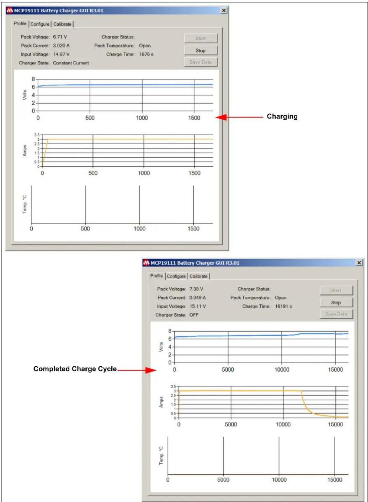
MCP19111 Battery Charger GUI Profile Configure Calibrate Pack Voltage: 11.19 V Charger Status: Pack Current: 4.027 A Pack Temperature: Open Input Voltage: 15.80 V Charge Time: 762 s Charger State: Constant Current Volts 12 10 6 4 2 0 0 200 400 600 Charging Volts Amps 5 4 3 2 1 0 0 200 400 600 Temp. °C 0 200 400 600 MCP19111 Battery Charger GUI Profile Configure Calibrate Pack Voltage: 12.58 V Charger Status: Pack Current: 0.061 A Pack Temperature: Open Input Voltage: 16.11 V Charge Time: 10959 s Charger State: OFF Volts 14 12 10 8 6 4 2 0 0 2000 4000 6000 8000 10000 Completed Charge Cycle Volts 5 4 3 2 1 0 0 2000 4000 6000 8000 10000 Temp. °CFIGURE 3-4: Charge Profile for Li-Ion Battery Pack (3-Cell, 4.00A Charge Current).

line
| Parameter | Value | |---------------------|-----------| | Pack Voltage | 6.34 V | | Pack Current | 1.817 A | | Input Voltage | 16.03 V | | Charge Time | 910 s | | Charge Status | Rapid Charge | | Charging | (no label) | | Amps | (no label) | | Temp. °C | (no label) | | Volts | (no label) | | Volts | (no label) | | Amps | (no label) | | Temp. °C | (no label) |FIGURE 3-5: VRLA Fast Charge Profile (3-Cell, 1.80A Charge Current).
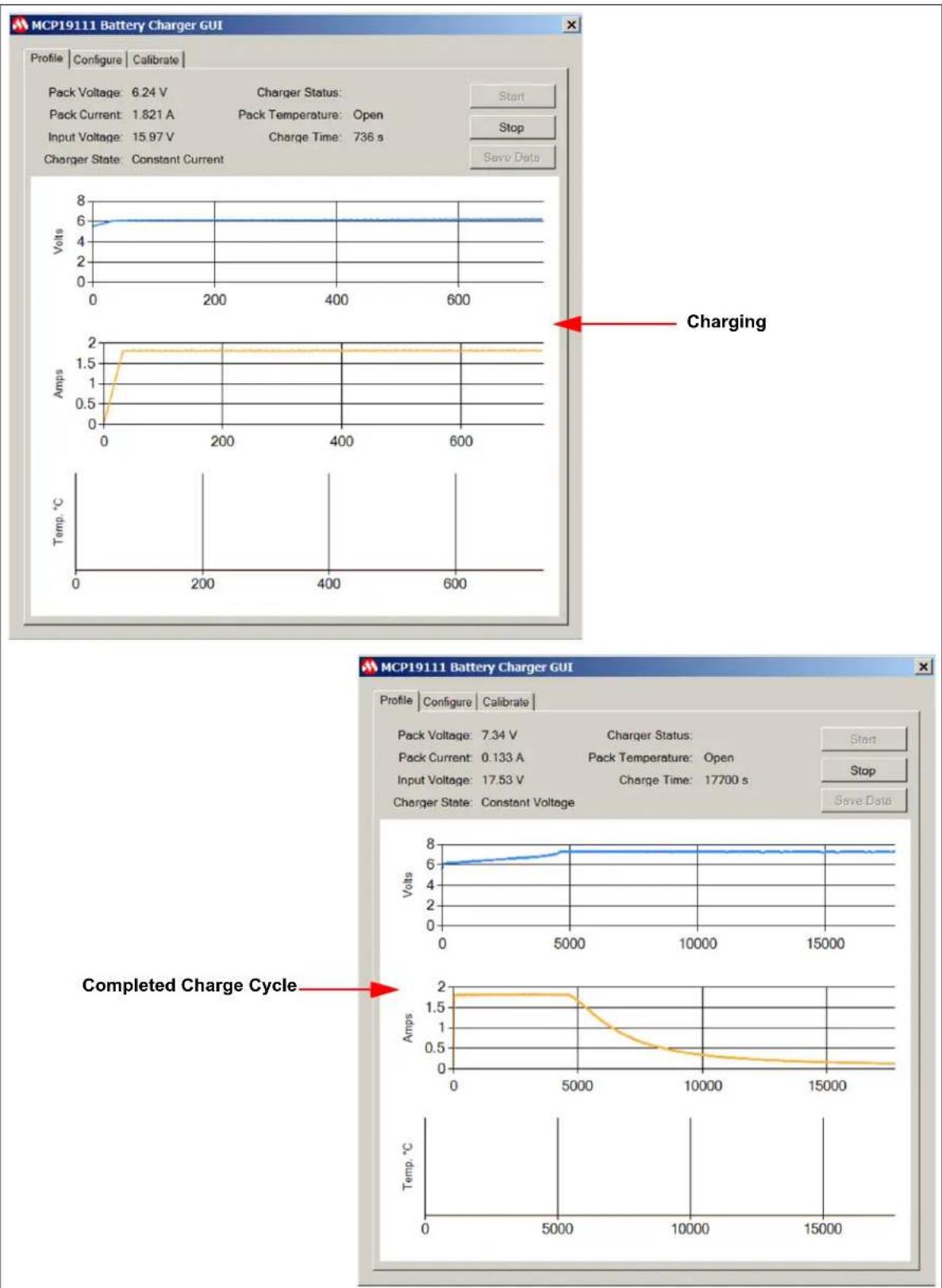
line
| Parameter | Value | |---------------------|-----------| | Pack Voltage | 7.34 V | | Pack Current | 0.133 A | | Pack Temperature | Open | | Input Voltage | 17.53 V | | Charge Time | 17700 s | | Charge State | Constant Current | | Charging | 6.24 V | | Amps | 1.5 Amps | | Temp. °C | 0 | | Completed Charge Cycle | 5000 |FIGURE 3-6: VRLA CCCP Charge Profile (3-Cell, 1.80A Charge Current).
line
| Time (s) | Voltage (V) | Current (A) | Charge (s) | |----------|-------------|-------------|------------| | 0 | 6.71 | 3.02 | 14.97 | | 500 | 6.71 | 3.02 | 14.97 | | 1000 | 6.71 | 3.02 | 14.97 | | 1500 | 6.71 | 3.02 | 14.97 |FIGURE 3-7: LiFePO4 Charge Profile (2-Cell, 3.0A Charge Current).
3.2 PROGRAMMING THE MCP19111 BATTERY CHARGER EVALUATION BOARD
The MCP19111 Battery Charger Evaluation Board comes with preprogrammed firmware installed. The following tools are required to reprogram the device.
- MPLAB ^® X Integrated Development System (IDE) (Version 2.05 or later)
- MPLAB XC8 Compiler (Version 1.3 or later)
• MCP19111 Battery Charger Evaluation Board Firmware
• MCP19111 Battery Charger Evaluation Board - PICkit™ 3 In-Circuit Debugger/Programmer
Follow the steps below to install all necessary software and start reprogramming the MCP19111 device:
- If MPLAB X IDE is already installed, go to Step 2. If not, download MPLAB X IDE from www.microchip.com/mplabx and follow the MPLAB X IDE installation instructions.
- If an XC8-compatible C compiler or an equivalent is already installed in MPLAB X IDE, go to Step 3. If not, a free version of Microchip's XC8 is available for download on www.microchip.com/mplabxc. The XC8 user guide, installation instructions and download links are available on this page.
- Download the MCP19111 Battery Charger Evaluation Board firmware archive (*.zip) from www.microchip.com/mcp19111 under "Documentation & Software".
- Unzip the MCP19111 Battery Charger Evaluation Board firmware archive. Place the MCP19111BatteryCharger.X project folder in the desired folder location.
- Power up the MCP19111 Battery Charger Evaluation Board.
- Connect the PICkit 3 In-Circuit Debugger to the MCP19111 Battery Charger Evaluation Board via the 6-pin connector, J3.
- Open MPLAB X IDE to load the MCP19111 Battery Charger Evaluation Board firmware. From the File menu, select Open Project (Figure 3-8).

text_image
MPLAB X IDE v2.15 File Edit View Navigate Source Refactor Run Debug Team Tools Window New Project... Ctrl+Shift+N New File... Ctrl+N Open Project... Ctrl+Shift+O Open Recent Project Import Open Team Project... Close Project Close All Projects Open File... Open Recent File Project Group Project Properties Save Ctrl+S Save As... Save All Ctrl+Shift+S Page Setup... Print... Ctrl+Alt+Shift+P Print to HTML... ExitFIGURE 3-8: Opening Project in MPLAB ^® X IDE.
- Browse for the location of the extracted firmware. Select "MCP19111BatteryCharger.X" from the list, then check the "Open as Main Project" option. Click on the Open Project button to complete loading the file.

text_image
Open Project Look in: MPLABXProjects MCP19111BatteryCharger.X Project Name: MCP19111BatteryCharger ✓ Open as Main Project □ Open Required Projects: File name: C:\Users\m15414\MPLABXProjects\MCP19111BatteryCharger.X Files of type: Project Folder Open Project CancelFIGURE 3-9: Loading Firmware into MPLAB ^® X IDE.
- Once the project is opened, click on the Make and Program Device Main Project (1) button on the toolbar to program the device. Wait until the program process is complete, as shown in Figure 3-10.
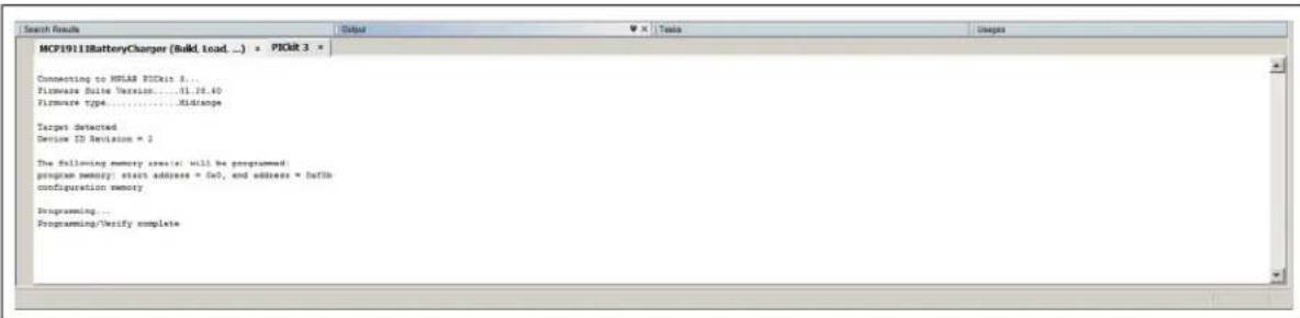
text_image
MCF19118BatteryCharger (Build, load ... ) * PIGR 3 * Connecting to HSLAR PICRat 8... Firmware Suite Version.....01.26.40 Firmware type.....Xidranpe Targets detected Device ID Revision = 2 The following memory creation: will be programmed: program memory: start address = 0x7, and address = libib configuration memory Programming... Programming/Verify completeFIGURE 3-10: Program Process Complete Window.
3.3 CALIBRATING THE MCP19111 BATTERY CHARGER EVALUATION BOARD
The evaluation board is calibrated prior to distribution. If calibration is lost as a result of programming, follow this procedure to recalibrate.
To calibrate the MCP19111 Battery Charger Evaluation Board, the following are required:
• MCP19111 Battery Charger Evaluation Board
• MCP19111 Battery Charger Evaluation Board GUI
- PICkit Serial Analyzer
- Two Variable Power Supplies (0-32V, 0-3.5A)
- Two Banana-Banana Power Cables
- Two Banana-Grabber Power Cables
- Digital Multimeter
To complete board calibration, follow the steps below:
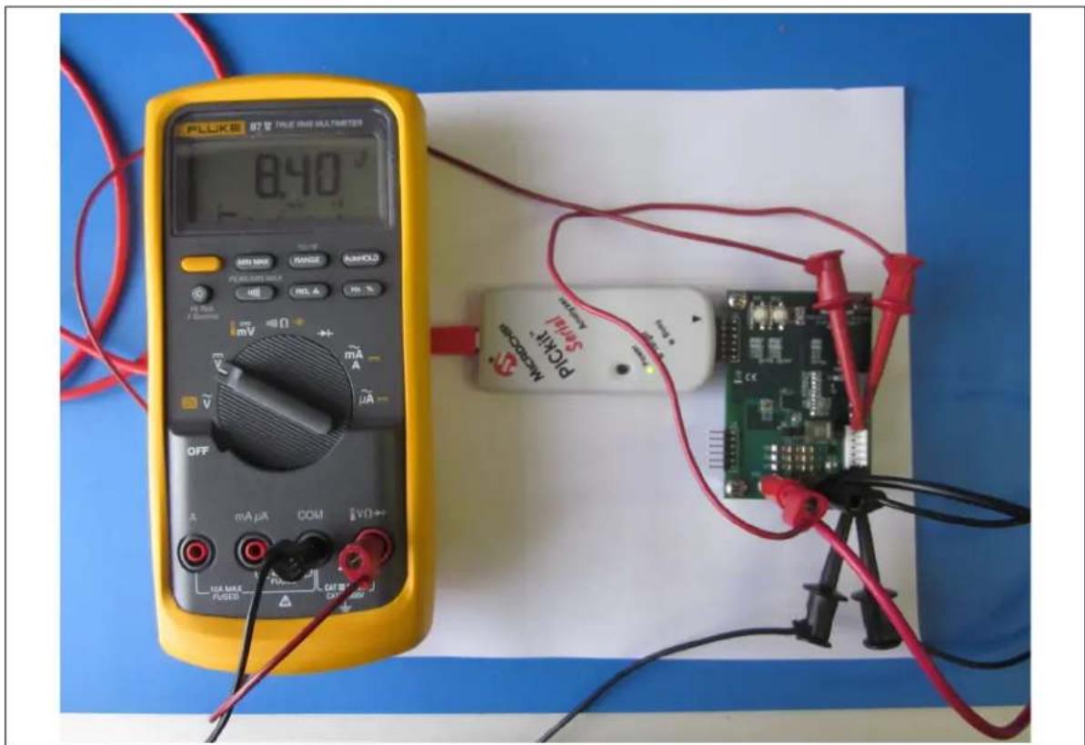
- Make sure the MCP19111 Battery Charger Evaluation Board is programmed with the most up-to-date firmware. Connect the V_IN and P_GND terminals of the battery charger board to a variable power supply and apply 8.40V.
- Run a banana-grabber cable from V_IN to Pin 1 or 2 of J1. This is to emulate the battery pack voltage that is read by the MCP19111 and displayed in the GUI for calibration.
- Run a second banana-grabber cable from the ground terminal to Pin 5 or 6 of J1. This provides a direct reference to ground.
- Attach a multimeter to the same respective pins in order to accurately measure the simulated battery voltage. Make sure the voltage read is 8.40V. Refer to Figure 3-11 for the proper voltage calibration setup.
text_image
FLUKE 078 TALE OAS MULTISTERS 0.40 ° SIN1000 GANGE BANKLO PEELENS SULK REL A HJ % mV mA μA OFF mA μA COM EVO+ 10A MAX PUGED CAT B MicroCap PICKIT SALM CNC-2000FIGURE 3-11: Voltage Calibration Setup.
- Make sure the GUI is installed on a computer. Connection from the GUI to the board can be made using a PICkit Serial Analyzer. Attach the PICkit analyzer to J2 on the board and connect to the computer hosting the GUI via USB. The LEDs of the PICkit analyzer should be visible when looking at the front of the board. Make sure that the
LED on the PICkit analyzer is ON and the LED is not flashing red. - In the GUI, select the Calibrate tab (see Figure 3-12). This tab contains boxes to read values into the ADC of the MCP19111 to initialize and calibrate the firmware for the specific evaluation board that has been attached.

text_image
MCP19111 Battery Charger GUI Profile Configure Calibrate Ibat 200 mA 1 A 3 A Read Calibration Begin Calibration Write Calibration Vin Vbat 8.4 V 12.6 V 16.8 VFIGURE 3-12: The Calibrate Tab.
- Click on the Begin Calibration button to enable the remaining fields on the tab. Confirm that the pack voltage being read is 8.40V with a multimeter and then click on the button with the corresponding value. This stores calibration values to the firmware to accommodate to that specific board. Repeat for 12.60V and 16.80V.
-
To calibrate the board for pack current, a slightly different configuration is needed. Disconnect the multimeter and connections from the J1 header.
-
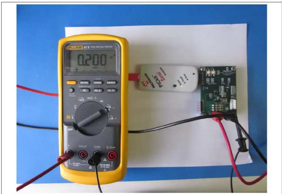
An additional power supply will be needed to provide constant-current values to the battery charger board. To ensure accurate calibration, input current should be run through a digital ammeter to display correct current values. This current should be connected to Pin 5 or 6 of J1. To complete the current loop, connect P_GND to the ground terminal of the constant-current power supply, so that both supplies share the same ground reference. Refer to Figure 3-13 for a correct configuration of the current calibration setup.
text_image
FLUKE 87 Ω TALE RED HA PETER 0.200 OFF mA μA COM VD 104 MAX PUBED SATE RED HA PETER Microcontroller SALAW PLCMA B-FIGURE 3-13: Current Calibration Setup.
- Run the constant-current supply at 200 mA, 1.00A and 3.00A, while ensuring the values are exact with the digital ammeter. When reaching 200 mA, select the button corresponding to 200 mA. Repeat this step for 1.00A and 3.00A by selecting the respective buttons in the application for each current value. When all values have been collected, click on the Write Calibration button. This stores the calibration values to the firmware of the MCP19111 device on the board. Figure 3-14 provides an example of proper calibration values.
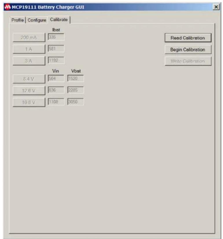
text_image
MCP19111 Battery Charger GUI Profile Configure Calibrate Ibat 200 mA 335 1 A 581 3 A 1192 Read Calibration Begin Calibration Write Calibration Vin Vbat 8.4 V 564 1520 12.6 V 636 2285 16.8 V 1108 3050FIGURE 3-14: GUI Calibration Tab with Proper Calibration Values.
- To verify whether a board is properly calibrated, click on the Read Calibration button while the board is powered and connected to the GUI.
- Error checking is performed during the calibration process. In case of an error message, recheck connections and restart the calibration process.
NOTES:
Appendix A. Schematic and Layouts
A.1 INTRODUCTION
This appendix contains the following schematics and layouts for the MCP19111 Battery Charger Evaluation Board:
- Board – Schematic
- Board – Schematic (Continued)
- Board – Top Silk
- Board – Top Copper and Silk
- Board – Top Copper
- Board – Mid Layer 1
- Board – Mid Layer 2
- Board – Bottom Copper
- Board – Bottom Copper and Silk
- Board – Bottom Silk
A.2 BOARD - SCHEMATIC
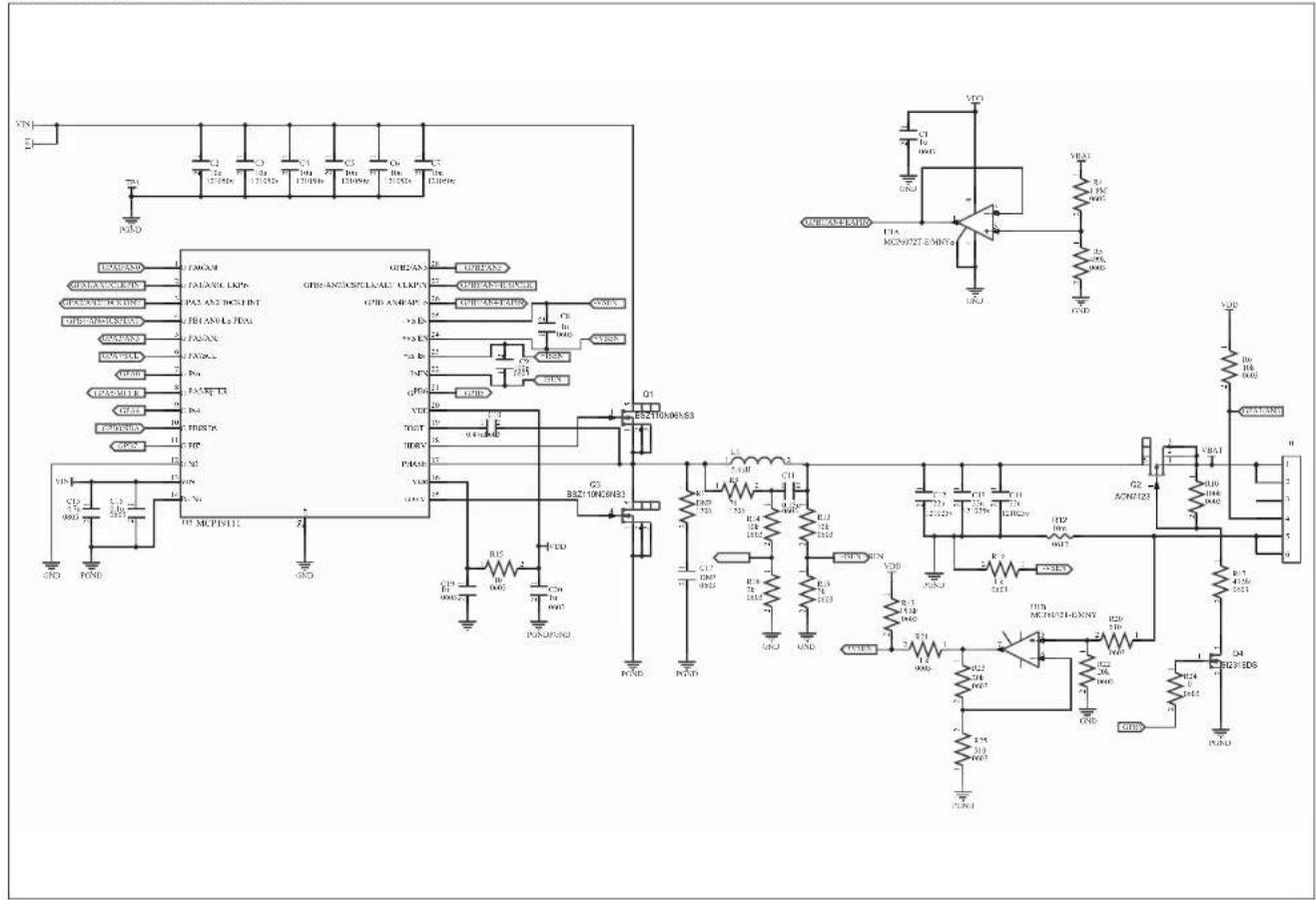
text_image
Circuit schematic diagram with labeled components including ICs, resistors, capacitors, and transistors, alongside an operational amplifier.A.3 BOARD - SCHEMATIC (CONTINUED)
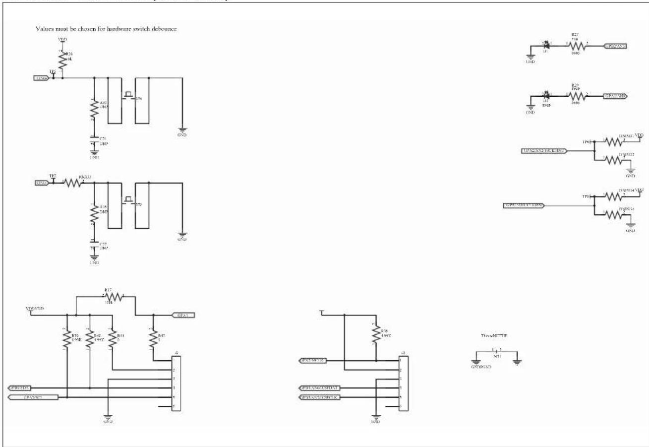
text_image
Values must be chosen for hardware switch debounce VDD R18 M4 UCC A20 JN5 C31 JN5 GND TE2 HACU3 E15 JN5 C31 JN5 GND VDD/WD R17 H4 E15 JN5 R11 JN5 GND VDD/WD R16 JN5 R11 JN5 GND VDD/WD R15 JN5 R11 JN5 GND VDD/WD R14 JN5 R11 JN5 GND VDD/WD R13 JN5 R11 JN5 GND VDD/WD R12 JN5 R11 JN5 GND VDD/WD R19 JN5 R11 JN5 GND VDD/WD R27 T10 D40 L12 DNP R29 DPB D40 GND L12 DNP R29 DPB D40 GND L12 DNP R29 DPB D40 GND L12 DNP R29 DPB D40 GND L12 DNP R29 DPB D40 GND L12 DNP R29 DPB T101. VDD D40/CD32. GND L12 DNP/CD32. VDD D40/CD32. GND L12 DNP/CD32. VDD/CD32. GND L12 DNP/CD32. VDD/CD32. GNDA.4 BOARD - TOP SILK
text_image
J2 BT1 BT2 R29 D2 D1 R27 MICROCHIP MCP1911 Battery Charger Evaluation Board ADM00513 C21 C22 R30 R28 R33 TP5 TP7 R31 R32 R34 TP6 R36 I2C RoHS CE U2 C15 C16 C10 Q1 Q3 L1 + + Battery J3 J3 Prog. TP3 TP4 C5 C6 C7 C3 C4 VIN PGNDA.5 BOARD – TOP COPPER AND SILK
text_image
J2 I2C RoHS CE J3 Prog. BT1 BT2 C21 R30 R28 TP5 TP7 R29 D2 D1 R27 C22 C35 R33 TP6 TP7 R31 R32 R34 R36 U2 TP8 R16 C8 U1 C1 R43 R21 R23 R25 R22 R20 R14 R13 C11 R9 Q1 Q3 C2 C5 C6 C7 TP3 TP4 Batter y J1 V1N PGND MICROCHIP MCP1911 Battery Charger Evaluation Board ADM00513A.6 BOARD - TOP COPPER

natural_image
Pure electrical circuit lines without any symbols or text, showing red and blue components (no text or labels)A.7 BOARD - MID LAYER 1
natural_image
Green circuit board layout with scattered white and gray circular components and a central white rectangle (no text or symbols)A.8 BOARD - MID LAYER 2
natural_image
Abstract geometric diagram with green lines, dots, and a green rectangle on white background (no text or symbols)A.9 BOARD - BOTTOM COPPER
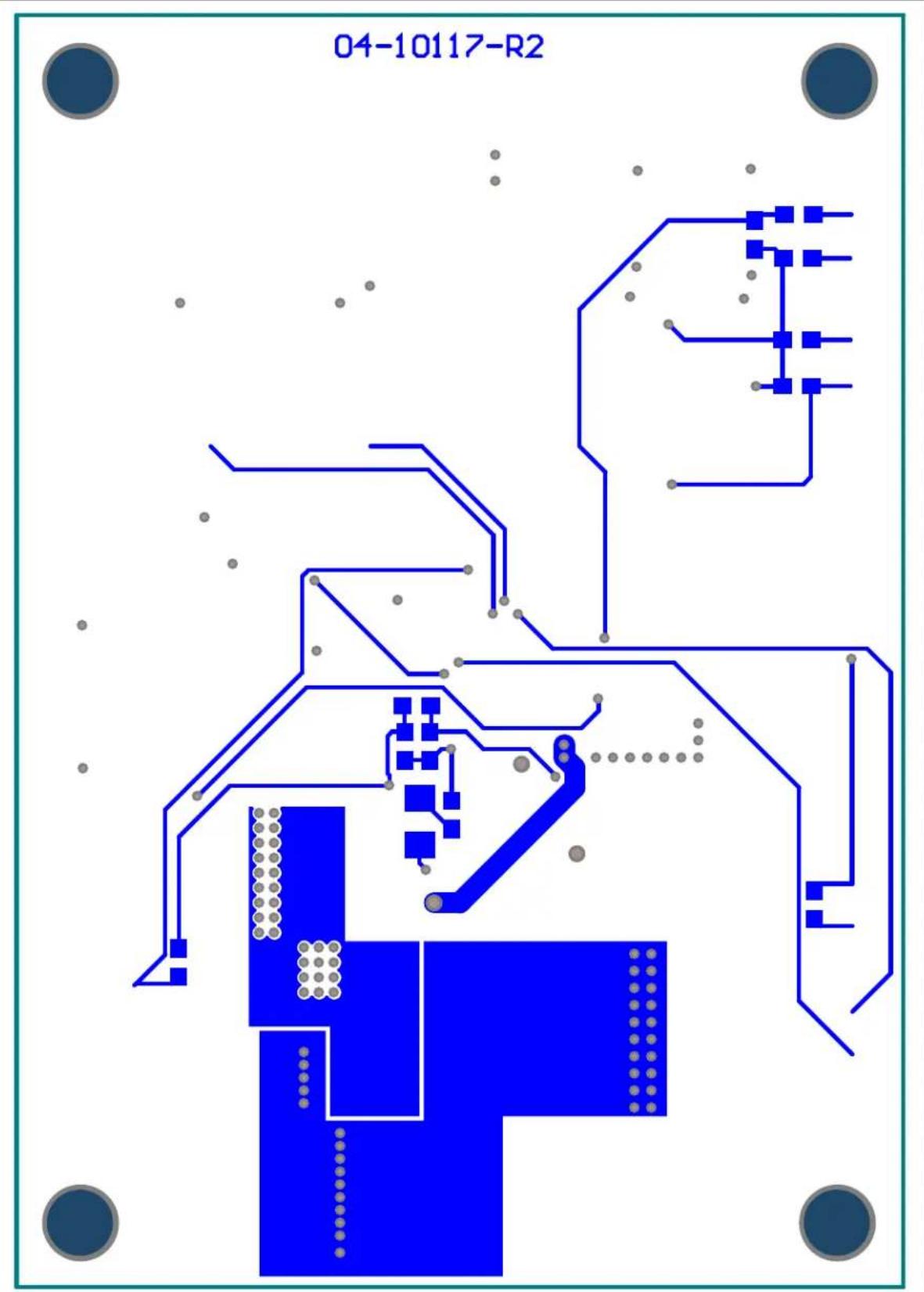
text_image
04-10117-R2A.10 BOARD - BOTTOM COPPER AND SILK

text_image
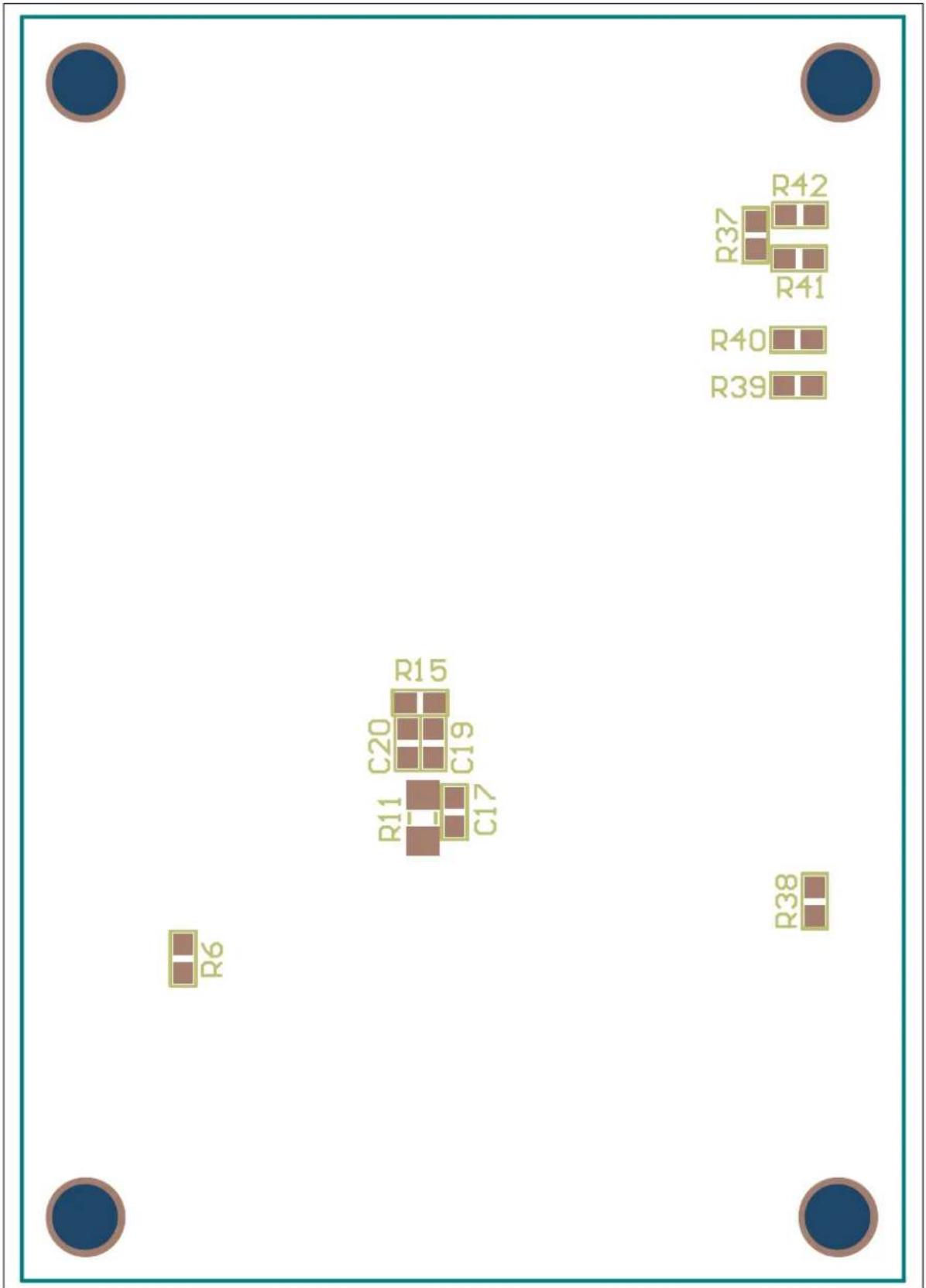
04-10117-R2 R42 R32 R41 R40 R39 R15 C20 C19 C17 R11 R6 R38A.11 BOARD - BOTTOM SILK
text_image
R6 R11 C20 C19 R15 C17 R37 R42 R41 R40 R39 R38NOTES:
Appendix B. Bill of Materials (BOM)
TABLE B-1: BILL OF MATERIALS (BOM) (1)
| Qty | Reference Description | Manufacturer Part Number | ||
| 2 BT1, BT2 Switch, Tactile, SPST-NO 0.05A, 12V E-Switch | ®, Inc. TL3301NF | 260QG | ||
| 3 | C1, C19, C20 | Cap., Cer., 1 μF, 16V, 10%, X7R, 0603 | TDK Corporation | C1608X7R1C105K080AC |
| 6 C2, C3, C4, C5, C6, C7 | Cap., Cer., 10 μF, 50V, 10%, X5R, 1210 | Taiyo Yuden Co., LTD. | UMK325BJ106KM-T | |
| 1 | C8 | Cap., Cer., 1000 pF, 50V, 10%, X7R, 0603 | KEMET® | C0603C102K5RACTU |
| 1 | C9 | Cap., Cer., 100 pF, 50V, 10%, X7R, 0603 | KEMET | C0603C101K5RACTU |
| 1 | C10 | Cap., Cer., 0.47 μF, 50V, 20%, X5R, 0603 | TDK Corporation | C1608X5R1H474M080AB |
| 1 | C11 | Cap., Cer., 0.47 μF, 25V, 10%, X7R, 0603 | TDK Corporation | C1608X5R1H474M080AB |
| 3 | C12, C13, C14 | Cap., Cer., 22 μF, 25V, 20%, X5R, 1210 | Taiyo Yuden Co., LTD. | TMK325BJ226MM-T |
| 1 | C15 | Cap., Cer., 4.7 μF, 50V, 10%, X5R, 0805 | TDK Corporation | C2012X5R1H475K125AB |
| 1 | C16 | Cap., Cer., 0.1 μF, 50V, 10%, X7R, 0603 | TDK Corporation | C1608X7R1H104K080AA |
| 0 | C17, C21, C22 | DO NOT POPULATE | — | — |
| 1 D1 LED, Super Red, 0603, SMD Vishay Semiconductor Opto Division | VLMS1300-GS08 | |||
| 0 | D2 | DO NOT POPULATE | — | — |
| 1 | J1 | Conn., Header, Vert, 6POS, 0.100, TIN | TE Connectivity, Ltd. | 640456-6 |
| 1 Housing - J1 (2) | Conn., Rcpt., HSNG, 6POS | TE Connectivity, Ltd | 1375820-6 | |
| 2 | J2, J3 | Conn., Header, R/A, SGL, 6POS, GOLD | 3M | 961106-5604-AR |
| 1 | L1 | Inductor, 5.6 μH, 13.67 mΩ | Coilcraft | XAL7070-562MEB |
| 2 | Q1, Q3 | MOSFET, N-CH, 60V, 20A, TSDSON-8 | Infineon Technologies AG | BSZ110N06NS3 G |
| 1 | Q2 | MOSF P, CH, 20V, 50A, DFN, 3.3 x 3.3 EP | Alpha & Omega Semiconductor Inc. | AON7423 |
| 1 | Q4 | MOSFET, N-CH, 40V, 3A, SOT23-3 | Vishay Siliconix | SI2318DS-T1-E3 |
| 1 PCB Printed Circuit Board - MCP19111 Battery Charger Evaluation Board | — 104-00513 | |||
| 1 | R4 | Res., 1.80 MΩ, 1/10W, 1%, 0603, SMD | Panasonic - ECG | ERJ-3EKF1804V |
| 1 | R5 | Res., 499 kΩ, 1/10W, 1%, 0603, SMD | Panasonic - ECG | ERJ-3EKF4993V |
| 5 R6, R13, R14, R28, R33 | Res., 10.0 kΩ, 1/10W, 1%, 0603, SMD | Panasonic - ECG | ERJ-3EKF1002V | |
| 1 | R9 | Res., 76Ω, 1/4W, 1%, 1206, SMD | Yageo Corporation | RC1206FR-07100RL |
| 2 | R10, R37 | Res., 100 kΩ, 1/10W, 1%, 0603, SMD | Panasonic - ECG | ERJ-3EKF1003V |
| 0 R11, R29, R30, R31, R32, R34, R35, R36 | DO NOT POPULATE | — | — | |
| 1 | R12 | Res., 0.010Ω, 1W, 1%, WIDE, 1206 | Susumu Co., LTD. | PRL1632-R010-F-T1 |
Note 1: The components listed in this Bill of Materials are representative of the PCB assembly. The released BOM used in manufacturing uses all RoHS-compliant components.
2: Optional mating connector for battery pack.
TABLE B-1: BILL OF MATERIALS (BOM) ^(1) (CONTINUED)
| Qty | Reference | Description | Manufacturer | Part Number |
| 1 | R15 | Res., 10Ω, 1/10W, 1%, 0603, SMD | Panasonic - ECG | ERJ-3EKF10R0V |
| 2 | R16, R21 | Res., 1 kΩ, 1/10W, 1%, 0603, SMD | Panasonic - ECG | ERJ-3EKF1001V |
| 1 | R17 | Res., 49.9 kΩ, 1/10W, 1%, 0603, SMD | Panasonic - ECG | ERJ-3EKF4992V |
| 2 | R18, R19 | Res., 2 kΩ, 1/10W, 1%, 0603, SMD | Panasonic - ECG | ERJ-3EKF2001V |
| 3 | R20, R25, R27 | Res., 510Ω, 1/10W, 1%, 0603, SMD | Panasonic - ECG | ERJ-3EKF5100V |
| 2 | R22, R23 | Res., 20.0 kΩ, 1/10W, 1%, 0603, SMD | Panasonic - ECG | ERJ-3EKF2002V |
| 3 | R24, R41, R42 | Res., 0.0Ω, 1/10W, JUMP, 0603, SMD | Panasonic® - ECG ERJ-3 | GEY0R00V |
| 3 | R38, R39, R40 | Res., 4.99 kΩ, 1/10W, 1%, 0603, SMD | Panasonic - ECG | ERJ-3EKF4991V |
| 1 | R43 | Res., 15.8 kΩ, 1/10W, 1%, 0603, SMD | Panasonic - ECG | ERJ-3EKF1582V |
| 2 TP3, TP4 Jack, Non-Insulated, .350" Keystone Electronics Corp. | 575-8 | |||
| 0 | TP5, TP6, TP7, TP8 | DO NOT POPULATE | — | — |
| 1 U1 | 1 | 10 μA, Dual Op Amp, Tape and Reel, 8-Lead SOIC Package | Microchip Technology Inc. | MCP6072T-E/SN |
| 1 U2 | Digitally Enhanced Power Analog Controller with Integrated Synchronous Driver, 28-Lead 5x5 QFN Package | Microchip Technology Inc. | MCP19111-E/MQ | |
| 4 6-32 Screw Machine Screw, Pan Phillips, 6-32 APM Hexseal ® | R6-32X3/8 2701 | |||
| 4 | 6-32 Standoff | Standoff, Hex, 6-32THR, ALUM, 1/2" | Keystone Electronics Corp. | 2210 |
Note 1: The components listed in this Bill of Materials are representative of the PCB assembly. The released BOM used in manufacturing uses all RoHS-compliant components.
2: Optional mating connector for battery pack.
Appendix C. Charge Profile Block Diagrams
C.1 INTRODUCTION
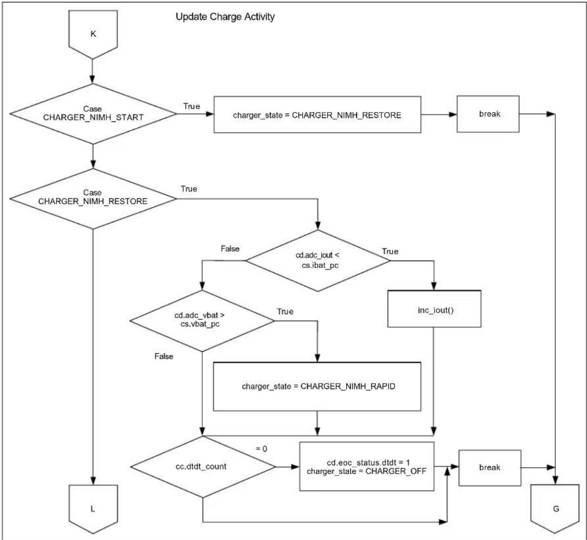
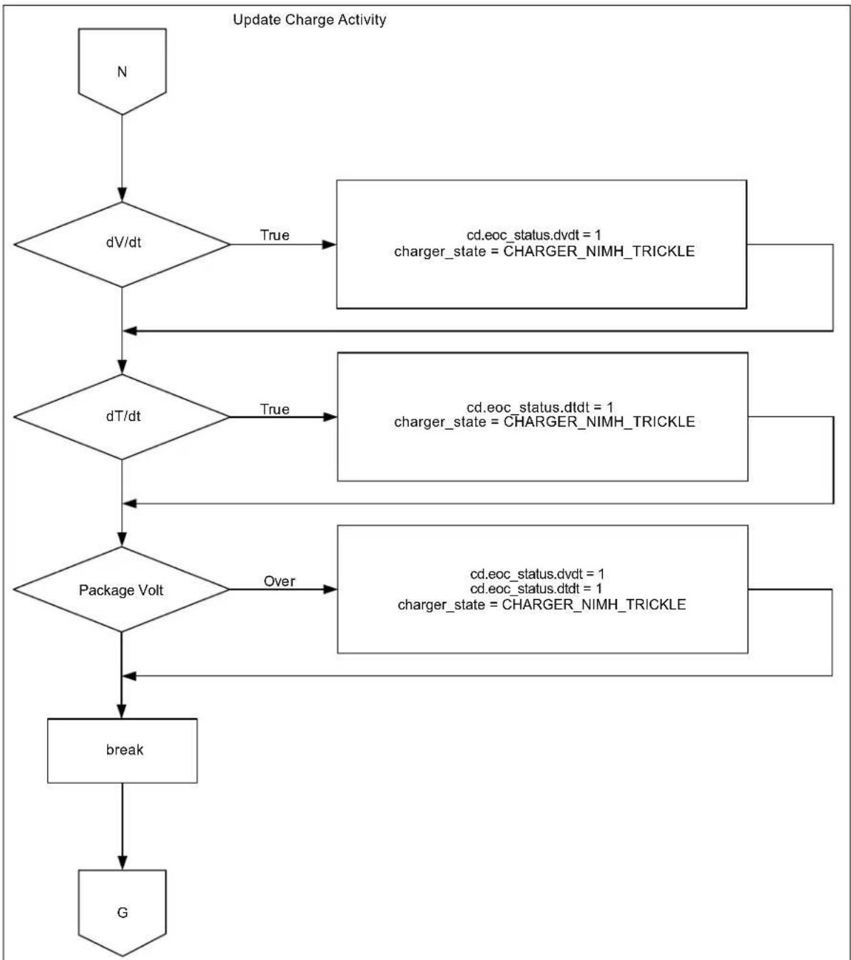
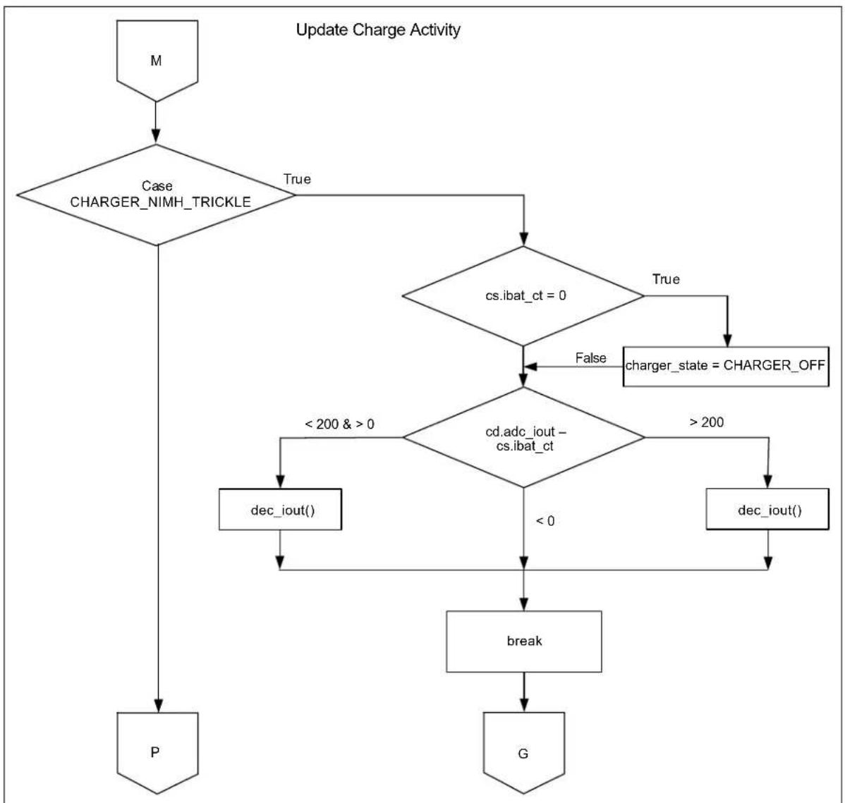
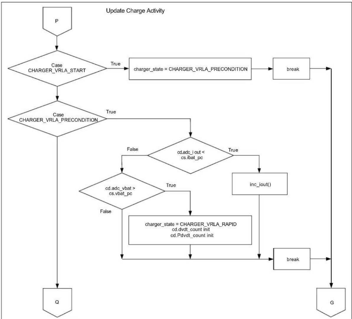
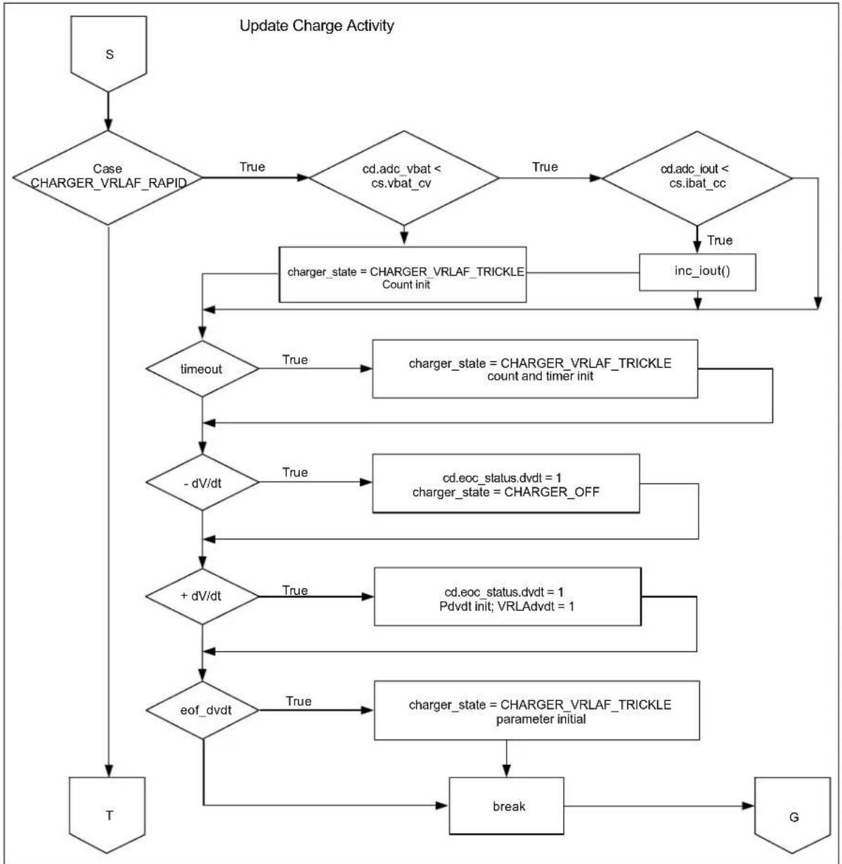
Figures C-1 to C-16 show block diagrams for the various charge profiles. The block diagrams show the flow of logic that enables the MCP19111 to control the charge cycle for efficient battery charging.
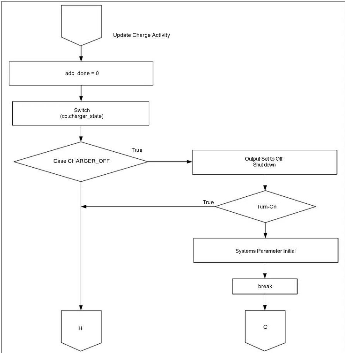
flowchart
graph TD
    A["Update Charge Activity"] --> B["adc_done = 0"]
    B --> C["Switch (cd.charger_state)"]
    C --> D{Case CHARGER_OFF}
    D -->|True| E["Output Set to Off Shut down"]
    E --> F{Turn-On}
    F -->|True| G["Systems Parameter Initial"]
    F -->|True| H["H"]
    G --> I["break"]
    I --> J["G"]
FIGURE C-1: Block Diagram of Battery Charger OFF-to-ON Logic.
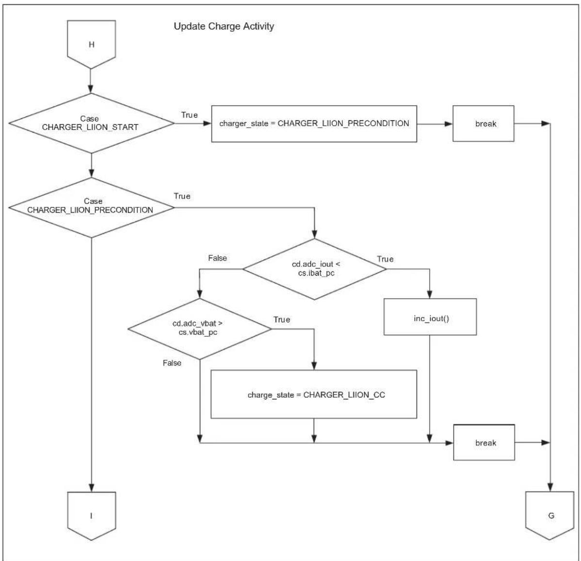
flowchart
graph TD
    A["H"] --> B{Case CHARGER_LIION_START}
    B -->|True| C["charger_state = CHARGER_LIION_PRECONDITION"]
    B -->|True| D{Case CHARGER_LIION_PRECONDITION}
    D -->|True| E{cd.adc_iout < cs.ibat_pc}
    D -->|False| F{cd.adc_vbat > cs.vbat_pc}
    F -->|False| G["charge_state = CHARGER_LIION_CC"]
    F -->|True| H["inc_iout()"]
    H --> I["break"]
    I --> J["G"]
    D --> K["I"]
FIGURE C-2: Block Diagram of Li-Ion Profile Initialization.
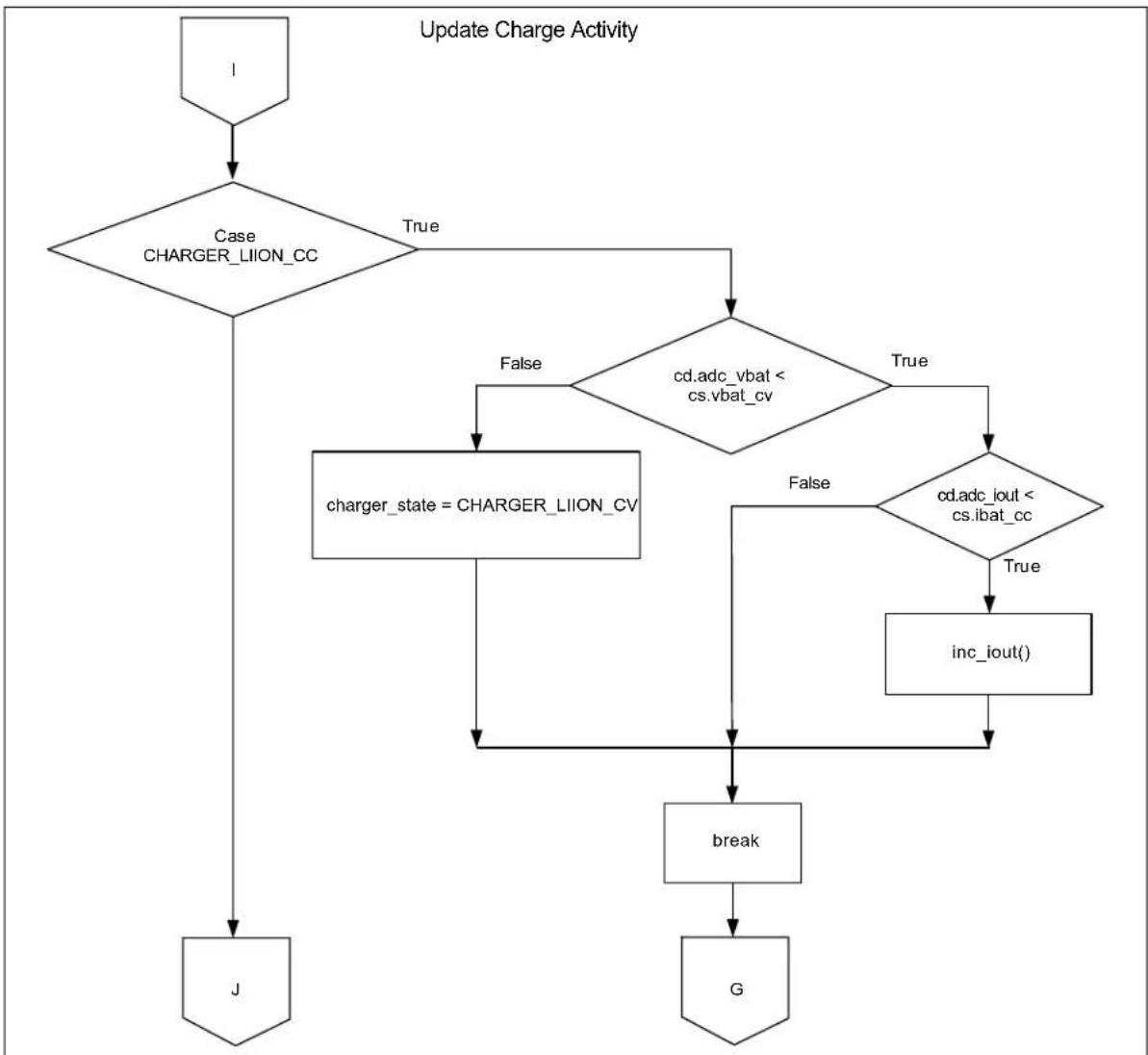
flowchart
graph TD
    A["1"] --> B{Case CHARGER_LION_CC}
    B -->|True| C{cd.adc_vbat < cs.vbat_cv}
    B -->|False| D["charger_state = CHARGER_LION_CV"]
    C -->|True| E{cd.adc_iout < cs.ibat_cc}
    C -->|False| F["inc_iout()"]
    D --> G["break"]
    E --> G
    F --> G
    G --> H["G"]
    I["J"] --> D
FIGURE C-3: Block Diagram of Transition to Li-Ion Constant-Current Charging Mode.

flowchart
graph TD
    A["J"] --> B{Case CHARGER_LIION_CV}
    B -->|True| C{cd.adc_vbat > cs.vbat_cv}
    C -->|True| D["dec_iout()"]
    C -->|True| E{cd.adc_iout < cs.ibat_cc}
    E -->|True| F["charger_state = CHARGER_LIION_OF_F"]
    E -->|True| G["break"]
    G --> H["G"]
    I["K"] --> B
FIGURE C-4: Block Diagram of Li-Ion Profile Termination.
flowchart
graph TD
    A["K"] --> B{Case CHARGER_NIMH_START}
    B -->|True| C["charger_state = CHARGER_NIMH_RESTORE"]
    C --> D["break"]
    D --> E["G"]
    B --> F{Case CHARGER_NIMH_RESTORE}
    F -->|True| G{cd.adc_iout < cs.ibat_pc}
    F -->|False| H{cd.adc_vbat > cs.vbat_pc}
    H -->|True| I["inc_iout()"]
    H -->|False| J{cc.dtdt_count}
    J -->|= 0| K["cd.eoc_status.dtdt = 1\ncharger_state = CHARGER_OFF"]
    K --> L["break"]
    L --> E
    B --> M["L"]
FIGURE C-5: Block Diagram of NiMH Profile Initialization and Transition to Rapid Charge Mode.

flowchart
graph TD
    L["L"] --> A{Case CHARGER_NIMH_RAPID}
    A -->|True| B{cs.ibat_cc - cd.adc_iout > 100}
    A -->|False| C{cs.ibat_cc - cd.adc_iout > 0}
    C -->|False| D["inc_iout()"]
    C -->|True| E["inc_iout() * 4"]
    B --> F{Charge Timeout}
    F -->|True| G["charger_state = CHARGER_NIMH_TRICKLE"]
    F -->|False| H["M"]
    G --> I["N"]
FIGURE C-6: Block Diagram of NiMH Profile Transition to Trickle Charge Mode.
flowchart
graph TD
    A["N"] --> B{dV/dt}
    B -->|True| C["cd.eoc_status.dvdt = 1\ncharger_state = CHARGER_NIMH_TRICKLE"]
    B -->|True| D{dT/dt}
    D -->|True| E["cd.eoc_status.dtdt = 1\ncharger_state = CHARGER_NIMH_TRICKLE"]
    D -->|True| F{Package Volt}
    F -->|Over| G["cd.eoc_status.dvdt = 1\ncharger_state = CHARGER_NIMH_TRICKLE"]
    F -->|Over| H["break"]
    H --> I["G"]
FIGURE C-7: Block Diagram of Voltage and Temperature Sense Termination Logic for NiMH Profile.
flowchart
graph TD
    A["M"] --> B{Case CHARGER_NIMH_TRICKLE}
    B -->|True| C{cs.ibat_ct = 0}
    B -->|False| D["charger_state = CHARGER_OFF"]
    C --> E{cd.adc_iout - cs.ibat_ct}
    E -->|< 200 & > 0| F["dec_iout()"]
    E -->|> 200| G["dec_iout()"]
    F --> H["break"]
    G --> I["G"]
    H --> J["P"]
FIGURE C-8: Block Diagram of NiMH Profile Charge Termination.
flowchart
graph TD
    P["P"] --> A{Case CHARGER_VRLA_START}
    A -->|True| B["charger_state = CHARGER_VRLA_PRECONDITION"]
    B --> C["break"]
    C --> D["G"]
    D --> E{Case CHARGER_VRLA_PRECONDITION}
    E -->|True| F{cd.adc_iout < cs.ibat_pc}
    E -->|False| G{cd.adc_vbat > cs.vbat_pc}
    G -->|False| H["charger_state = CHARGER_VRLA_RAPID cd.dvdt_count init cd.PdvdL_count init"]
    F -->|True| I["inc_iout()"]
    I --> J["break"]
    J --> D
    F --> K{cd.adc_iout < cs.ibat_pc}
    K -->|True| L["charger_state = CHARGER_VRLA_RAPID cd.dvdt_count init cd.PdvdL_count init"]
    L --> M["break"]
    M --> N["G"]
    N --> O["Q"]
FIGURE C-9: Block Diagram of VRLA Profile Initialization and Transition to Rapid Charge Mode.
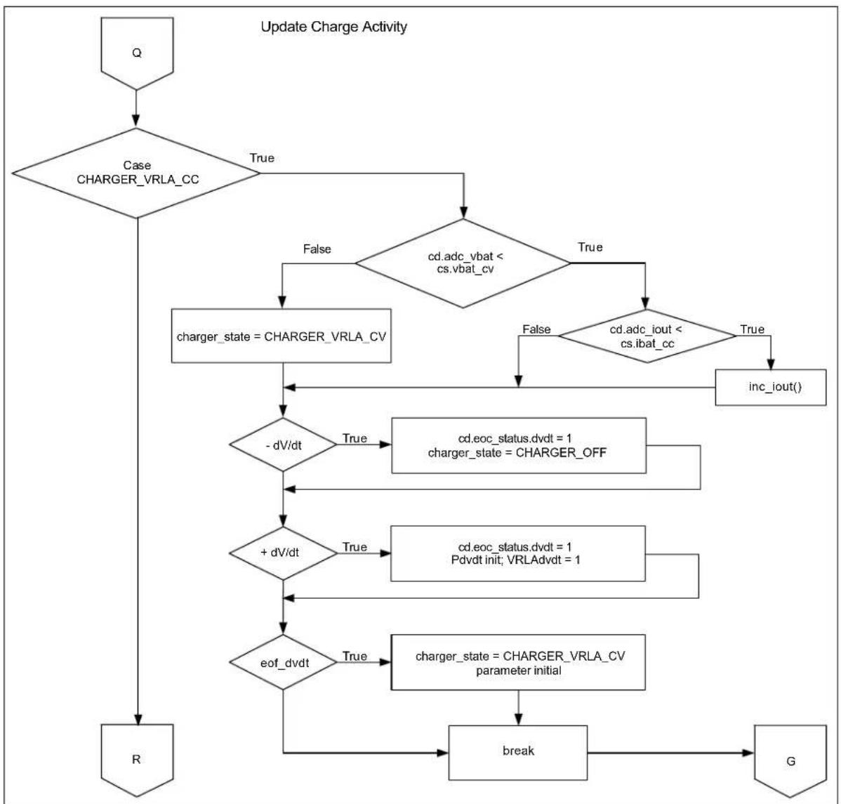
flowchart
graph TD
    A["Q"] --> B{Case CHARGER_VRLA_CC}
    B -->|True| C{cd.adc_vbat < cs.vbat_cv}
    C -->|False| D["charger_state = CHARGER_VRLA_CV"]
    C -->|True| E{cd.adc_iout < cs.ibat_cc}
    E -->|False| F["inc_iout()"]
    E -->|True| G["inc_iout()"]
    D --> H{-dV/dt}
    F --> H
    H -->|True| I["cd.eoc_status.dvdt = 1\ncharger_state = CHARGER_OFF"]
    H -->|False| J{+dV/dt}
    J -->|True| K["cd.eoc_status.dvdt = 1\nPdvdt init; VRLAdvdt = 1"]
    J -->|False| L{eof_dvdt}
    L -->|True| M["charger_state = CHARGER_VRLA_CV\nparameter initial"]
    L -->|False| N["break"]
    M --> O["G"]
    N --> O
    O --> P["R"]
FIGURE C-10: Block Diagram of Transition to Constant-Voltage Mode.

flowchart
graph TD
    A["R"] --> B{Case CHARGER_VRLA_CV}
    B -->|True| C{cd.adc_vbat > cs.vbat_cv}
    C -->|True| D["dec_iout()"]
    C -->|False| E{cd.adc_iout < cs.ibat_ct}
    D --> E
    E -->|True| F["charger_state = CHARGER_OFF"]
    E -->|False| G["break"]
    F --> H["charger_state = CHARGER_VRLAF_RESTORE"]
    G --> I["break"]
    H --> J{Case CHARGER_VRLAF_START}
    I --> J
    J -->|True| K{charger_state = CHARGER_VRLAF_RESTORE}
    K -->|True| L["charger_state = CHARGER_VRLAF_RESTORE"]
    K -->|False| M{charger_state = CHARGER_VRLAF_RAPID}
    M --> N["break"]
    N --> O["G"]
    J -->|True| P{cd.adc_iout < cs.ibat_pc}
    P -->|True| Q["charger_state = CHARGER_VRLAF_RAPID"]
    P -->|False| R["inc_iout()"]
    R --> S["break"]
    S --> O
    S --> T["S"]
FIGURE C-11: Block Diagram of VRLA CCCP Charge Termination and VRLA Fast Profile Initialization.
flowchart
graph TD
    S["S"] --> A{Case CHARGER_VRLAF_RAPID}
    A -->|True| B{cd.adc_vbat < cs.vbat_cv}
    B -->|True| C{cd.adc_iout < cs.ibat_cc}
    C -->|True| D["inc_iout()"]
    D --> E{timeout}
    E -->|True| F["charger_state = CHARGER_VRLAF_TRICKLE Count init"]
    F --> G{-dV/dt}
    G -->|True| H["charger_state = CHARGER_VRLAF_TRICKLE count and timer init"]
    H --> I{+dV/dt}
    I -->|True| J["cd.eoc_status.dvdt = 1\ncharger_state = CHARGER_OFF"]
    J --> K{eof_dvdt}
    K -->|True| L["charger_state = CHARGER_VRLAF_TRICKLE parameter initial"]
    L --> M["break"]
    M --> N["G"]
    N --> O["T"]
FIGURE C-12: Block Diagram of VRLA Fast Charge Profile Logic.

flowchart
graph TD
    A["T"] --> B{Case CHARGER_VRLAF_TRICKLE}
    B -->|True| C{cs.ibat_ct = 0}
    C -->|True| D["charger_state = CHARGER_OFF"]
    C -->|< 200 & > 0| E{cs.adc_iout - cs.ibat_ct}
    E -->|< 0| F["dec_iout()"]
    E -->|> 200| G["dec_iout_f()"]
    E --> H["+ dV/dt"]
    H -->|True| I["cd.eoc_status.dvdt = 1 Pdvdt init; VRLAdvdt = 1"]
    H -->|False| J["eof_dvdt"]
    J -->|True| K["charger_state = CHARGER_OFF parameter initial"]
    J -->|False| L["Timeout"]
    K --> M["charger_state = CHARGER_OFF count and timer init"]
    L --> N["break"]
    M --> O["G"]
    N --> O
    O --> P["G"]
FIGURE C-13: Block Diagram of VRLA Fast Trickle Charge Mode and Profile Termination.
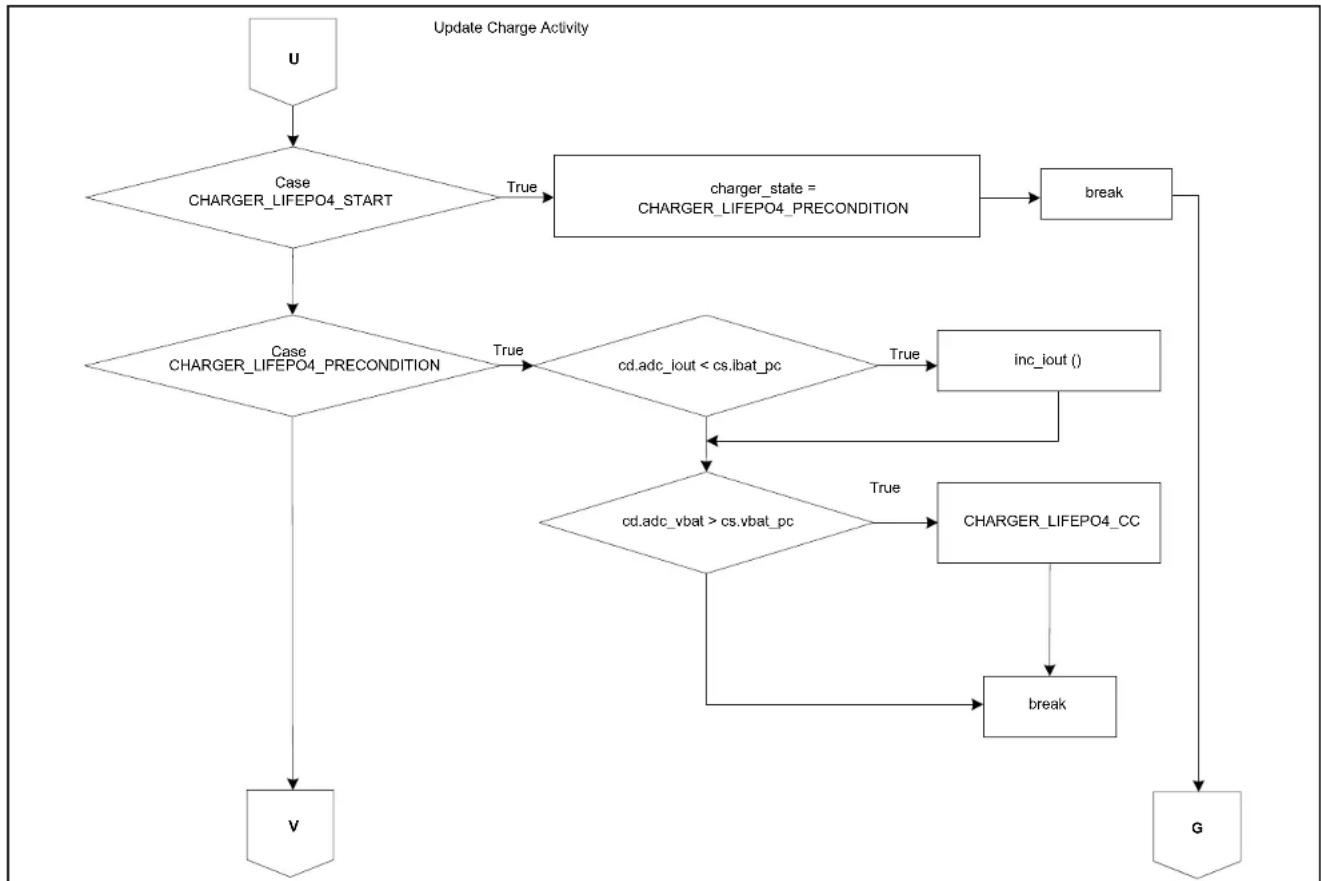
flowchart
graph TD
    U["U"] --> A{Case CHARGER_LIFEPO4_START}
    A -->|True| B["charger_state = CHARGER_LIFEPO4_PRECONDITION"]
    A -->|True| C{Case CHARGER_LIFEPO4_PRECONDITION}
    C -->|True| D{cd.adc_iout < cs.ibat_pc}
    D -->|True| E["inc_iout()"]
    D -->|False| F{cd.adc_vbat > cs.vbat_pc}
    E --> G["charger_LIFEPO4_CC"]
    F -->|True| H["charger_LIFEPO4_CC"]
    F -->|False| I["break"]
    I --> G
    V["V"] --> C
    G --> G
    H --> G
    I --> G
FIGURE C-14: Block Diagram of LiFEPO4 Profile Initialization.
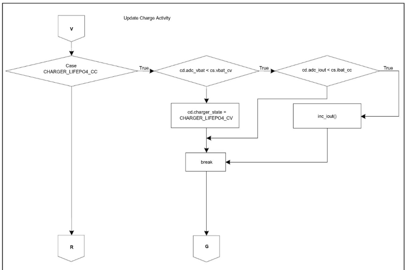
flowchart
graph TD
    A["v"] --> B{Case CHARGER_LIFEPO4_CC}
    B -->|True| C{cd.adc_vbat < cs.vbat_cv}
    C -->|True| D{cd.adc_iout < cs.ibat_cc}
    D -->|True| E["inc_iout()"]
    D --> F["cd.charger_state = CHARGER_LIFEPO4_CV"]
    F --> G["break"]
    G --> H["G"]
    H --> I["R"]
    I --> B
FIGURE C-15: Block Diagram of Transition to LiFEPO4 Constant-Current Charging Mode.

flowchart
graph TD
    S["S"] --> A{Case CHARGER_LIFEPO4_CV}
    A -->|True| B{cd.adc_vbat > cs.vbat_cv}
    B -->|True| C["dec_iout()"]
    B -->|True| D["cd.charger_state = CHARGER_OFF"]
    C --> E["break"]
    D --> E
    E --> F["T"]
    F --> G["T"]
FIGURE C-16: Block Diagram of LiFEPO4 Profile Termination.
NOTES:
Worldwide Sales and Service
AMERICAS
Corporate Office
2355 West Chandler Blvd.
Chandler, AZ 85224-6199
Tel: 480-792-7200
Fax: 480-792-7277
Technical Support:
http://www.microchip.com/
support
Web Address:
www.microchip.com
Atlanta
Duluth, GA
Tel: 678-957-9614
Fax: 678-957-1455
Austin, TX
Tel: 512-257-3370
Boston
Westborough, MA
Tel: 774-760-0087
Fax: 774-760-0088
Chicago
Itasca, IL
Tel: 630-285-0071
Fax: 630-285-0075
Cleveland
Independence, OH
Tel: 216-447-0464
Fax: 216-447-0643
Dallas
Addison, TX
Tel: 972-818-7423
Fax: 972-818-2924
Detroit
Novi, M
Tel: 248-848-4000
Houston, TX
Tel: 281-894-5983
Indianapolis
Noblesville, IN
Tel: 317-773-8323
Fax: 317-773-5453
Los Angeles
Mission Viejo, CA
Tel: 949-462-9523
Fax: 949-462-9608
New York, NY
Tel: 631-435-6000
San Jose, CA
Tel: 408-735-9110
Canada - Toronto
Tel: 905-673-0699
Fax: 905-673-6509
ASIA/PACIFIC
Asia Pacific Office
Suites 3707-14, 37th Floor
Tower 6, The Gateway
Harbour City, Kowloon
Hong Kong
Tel: 852-2943-5100
Fax: 852-2401-3431
Australia - Sydney
Tel: 61-2-9868-6733
Fax: 61-2-9868-6755
China - Beijing
Tel: 86-10-8569-7000
Fax: 86-10-8528-2104
China - Chengdu
Tel: 86-28-8665-5511
Fax: 86-28-8665-7889
China - Chongqing
Tel: 86-23-8980-9588
Fax: 86-23-8980-9500
China - Dongguan
Tel: 86-769-8702-9880
China - Hangzhou
Tel: 86-571-8792-8115
Fax: 86-571-8792-8116
China - Hong Kong SAR
Tel: 852-2943-5100
Fax: 852-2401-3431
China - Nanjing
Tel: 86-25-8473-2460
Fax: 86-25-8473-2470
China - Qingdao
Tel: 86-532-8502-7355
Fax: 86-532-8502-7205
China - Shanghai
Tel: 86-21-5407-5533
Fax: 86-21-5407-5066
China - Shenyang
Tel: 86-24-2334-2829
Fax: 86-24-2334-2393
China - Shenzhen
Tel: 86-755-8864-2200
Fax: 86-755-8203-1760
China - Wuhan
Tel: 86-27-5980-5300
Fax: 86-27-5980-5118
China - Xian
Tel: 86-29-8833-7252
Fax: 86-29-8833-7256
ASIA/PACIFIC
China - Xiamen
Tel: 86-592-2388138
Fax: 86-592-2388130
China - Zhuhai
Tel: 86-756-3210040
Fax: 86-756-3210049
India - Bangalore
Tel: 91-80-3090-4444
Fax: 91-80-3090-4123
India - New Delhi
Tel: 91-11-4160-8631
Fax: 91-11-4160-8632
India - Pune
Tel: 91-20-3019-1500
Japan - Osaka
Tel: 81-6-6152-7160
Fax: 81-6-6152-9310
Japan - Tokyo
Tel: 81-3-6880-3770
Fax: 81-3-6880-3771
Korea - Daegu
Tel: 82-53-744-4301
Fax: 82-53-744-4302
Korea - Seoul
Tel: 82-2-554-7200
Fax: 82-2-558-5932 or
82-2-558-5934
Malaysia - Kuala Lumpur
Tel: 60-3-6201-9857
Fax: 60-3-6201-9859
Malaysia - Penang
Tel: 60-4-227-8870
Fax: 60-4-227-4068
Philippines - Manila
Tel: 63-2-634-9065
Fax: 63-2-634-9069
Singapore
Tel: 65-6334-8870
Fax: 65-6334-8850
Taiwan - Hsin Chu
Tel: 886-3-5778-366
Fax: 886-3-5770-955
Taiwan - Kaohsiung
Tel: 886-7-213-7828
Taiwan - Taipei
Tel: 886-2-2508-8600
Fax: 886-2-2508-0102
Thailand - Bangkok
Tel: 66-2-694-1351
Fax: 66-2-694-1350
EUROPE
Austria - Wels
Tel: 43-7242-2244-39
Fax: 43-7242-2244-393
Denmark - Copenhagen
Tel: 45-4450-2828
Fax: 45-4485-2829
France - Paris
Tel: 33-1-69-53-63-20
Fax: 33-1-69-30-90-79
Germany - Dusseldorf
Tel: 49-2129-3766400
Germany - Munich
Tel: 49-89-627-144-0
Fax: 49-89-627-144-44
Germany - Pforzheim
Tel: 49-7231-424750
Italy - Milan
Tel: 39-0331-742611
Fax: 39-0331-466781
Italy - Venice
Tel: 39-049-7625286
Netherlands - Drunen
Tel: 31-416-690399
Fax: 31-416-690340
Poland - Warsaw
Tel: 48-22-3325737
Spain - Madrid
Tel: 34-91-708-08-90
Fax: 34-91-708-08-91
Sweden - Stockholm
Tel: 46-8-5090-4654
UK - Wokingham
Tel: 44-118-921-5800
Fax: 44-118-921-5820