MCP73832 - Electronic component Microchip - Free user manual and instructions
Find the device manual for free MCP73832 Microchip in PDF.

User questions about MCP73832 Microchip
0 question about this device. Answer the ones you know or ask your own.
Ask a new question about this device
Download the instructions for your Electronic component in PDF format for free! Find your manual MCP73832 - Microchip and take your electronic device back in hand. On this page are published all the documents necessary for the use of your device. MCP73832 by Microchip.
USER MANUAL MCP73832 Microchip
Power Path Management
Reference Design
Note the following details of the code protection feature on Microchip devices:
• Microchip products meet the specification contained in their particular Microchip Data Sheet.
- Microchip believes that its family of products is one of the most secure families of its kind on the market today, when used in the intended manner and under normal conditions.
- There are dishonest and possibly illegal methods used to breach the code protection feature. All of these methods, to our knowledge, require using the Microchip products in a manner outside the operating specifications contained in Microchip's Data Sheets. Most likely, the person doing so is engaged in theft of intellectual property.
• Microchip is willing to work with the customer who is concerned about the integrity of their code.
- Neither Microchip nor any other semiconductor manufacturer can guarantee the security of their code. Code protection does not mean that we are guaranteeing the product as “unbreakable.”
Code protection is constantly evolving. We at Microchip are committed to continuously improving the code protection features of our products. Attempts to break Microchip's code protection feature may be a violation of the Digital Millennium Copyright Act. If such acts allow unauthorized access to your software or other copyrighted work, you may have a right to sue for relief under that Act.
Information contained in this publication regarding device applications and the like is provided only for your convenience and may be superseded by updates. It is your responsibility to ensure that your application meets with your specifications. MICROCHIP MAKES NO REPRESENTATIONS OR WARRANTIES OF ANY KIND WHETHER EXPRESS OR IMPLIED, WRITTEN OR ORAL, STATUTORY OR OTHERWISE, RELATED TO THE INFORMATION, INCLUDING BUT NOT LIMITED TO ITS CONDITION, QUALITY, PERFORMANCE, MERCHANTABILITY OR FITNESS FOR PURPOSE. Microchip disclaims all liability arising from this information and its use. Use of Microchip devices in life support and/or safety applications is entirely at the buyer's risk, and the buyer agrees to defend, indemnify and hold harmless Microchip from any and all damages, claims, suits, or expenses resulting from such use. No licenses are conveyed, implicitly or otherwise, under any Microchip intellectual property rights.
Trademarks
The Microchip name and logo, the Microchip logo, Accuron, dsPIC, KEELOQ, KEELOQ logo, MPLAB, PIC, PICmicro, PICSTART, PRO MATE, rfPIC and SmartShunt are registered trademarks of Microchip Technology Incorporated in the U.S.A. and other countries.
FilterLab, Linear Active Thermistor, MXDEV, MXLAB, SEEVAL, SmartSensor and The Embedded Control Solutions Company are registered trademarks of Microchip Technology Incorporated in the U.S.A.
Analog-for-the-Digital Age, Application Maestro, CodeGuard, dsPICDEM, dsPICDEM.net, dsPICworks, dsSPEAK, ECAN, ECONOMONITOR, FanSense, In-Circuit Serial Programming, ICSP, ICEPIC, Mindi, MiWi, MPASM, MPLAB Certified logo, MPLIB, MPLINK, mTouch, PICkit, PICDEM, PICDEM.net, PICtail, PIC ^32 logo, PowerCal, PowerInfo, PowerMate, PowerTool, REAL ICE, rfLAB, Select Mode, Total Endurance, UNI/O, WiperLock and ZENA are trademarks of Microchip Technology Incorporated in the U.S.A. and other countries.
SQTP is a service mark of Microchip Technology Incorporated in the U.S.A.
All other trademarks mentioned herein are property of their respective companies.
© 2008, Microchip Technology Incorporated, Printed in the U.S.A., All Rights Reserved.
Printed on recycled paper.
QUALITY MANAGEMENT SYSTEM CERTIFIED BY DNV
=ISO/TS 16949:2002=
Microchip received ISO/TS-16949:2002 certification for its worldwide headquarters, design and wafer fabrication facilities in Chandler and Tempe, Arizona; Gresham, Oregon and design centers in California and India. The Company's quality system processes and procedures are for its PIC® MCUs and dsPIC® DSCs, KEELOQ® code hopping devices, Serial EEPROMs, microperipherals, nonvolatile memory and analog products. In addition, Microchip's quality system for the design and manufacture of development systems is ISO 9001:2000 certified.
Table of Contents
Preface ....1
Introduction....1
Document Layout 1
Conventions Used in this Guide.... 2
Recommended Reading.... 3
The Microchip Web Site 3
Customer Support 3
Document Revision History.... 3
Chapter 1. Product Overview
1.1 Introduction 5
1.2 What is the Li-Ion Battery Charger System Power Path Management Reference Design? 6
1.3 What the Li-Ion Battery Charger System Power Path Management Reference Design kit Includes 6
Chapter 2. Installation and Operation
2.1 Introduction 7
2.2 Features 7
2.3 Getting Started 8
Appendix A. Schematic and Layouts
A.1 Introduction 11
A.2 Board – Schematic 12
A.3 Board – Top Layer 13
A.4 Board – Top Metal Layer 13
A.5 Board – Bottom Layer 14
Appendix B. Bill Of Materials (BOM)
Worldwide Sales and Service 16
NOTES:
Preface
NOTICE TO CUSTOMERS
All documentation becomes dated, and this manual is no exception. Microchip tools and documentation are constantly evolving to meet customer needs, so some actual dialogs and/or tool descriptions may differ from those in this document. Please refer to our web site (www.microchip.com) to obtain the latest documentation available.
Documents are identified with a "DS" number. This number is located on the bottom of each page, in front of the page number. The numbering convention for the DS number is "DSXXXXXA", where "XXXXX" is the document number and "A" is the revision level of the document.
For the most up-to-date information on development tools, see the MPLAB ^® IDE on-line help. Select the Help menu, and then Topics to open a list of available on-line help files.
INTRODUCTION
This chapter contains general information that will be useful to know before using the Li-Ion System PPM Reference Design. Items discussed in this chapter include:
- Document Layout
- Conventions Used in this Guide
• Recommended Reading
• The Microchip Web Site - Customer Support
• Document Revision History
DOCUMENT LAYOUT
This document describes how to use the Li-Ion System PPM Reference Design as a development tool to emulate and debug firmware on a target board. The manual layout is as follows:
- Chapter 1. "Product Overview" – Important information about the Li-Ion System PPM Reference Design.
- Chapter 2. “Installation and Operation” – Includes instructions on how to get started with this user’s guide and a description of the user’s guide.
- Appendix A. “Schematic and Layouts” – Shows the schematic and layout diagrams for the Li-Ion System PPM Reference Design.
- Appendix B. “Bill Of Materials (BOM)” – Lists the parts used to build the Li-Ion System PPM Reference Design.
CONVENTIONS USED IN THIS GUIDE
This manual uses the following documentation conventions:
DOCUMENTATION CONVENTIONS
| Description Represents Examples | ||
| Arial font: | ||
| Italic characters Referenced books | MPLAB | ^ IDE User's Guide |
| Emphasized text ...is the only compiler... | ||
| Initial caps A window the Output | window | |
| A dialog the Settings dialog | ||
| A menu selection select Enable Programmer | ||
| Quotes A field name in a window or dialog | "Save project before build" | |
| Underlined, italic text with right angle bracket | A menu path File>Save | —— |
| Bold characters A dialog button | Click OK | |
| A tab | Click the Power tab | |
| N'Rnnnn | A number in verilog format, where N is the total number of digits, R is the radix and n is a digit. | 4'b0010, 2'hF1 |
| Text in angle brackets <> | A key on the keyboard | Press,, |
| Courier New font: | ||
| Plain Courier New | Sample source code | #define START |
| Filenames | autoexec.bat | |
| File paths | c:\mcc18\h | |
| Keywords | _asm, _endasm, static | |
| Command-line options | -Opa+, -Opa- | |
| Bit values | 0, 1 | |
| Constants | 0xFF, 'A' | |
| Italic Courier New | A variable argument | file.o, where file can be any valid filename |
| Square brackets [] | Optional arguments | mcc18 [options] file [options] |
| Curly brackets and pipe character: { | } | Choice of mutually exclusive arguments; an OR selection | errorlevel {0|1} |
| Ellipses... Replaces repeated text var_name [, | var_name...] | |
| Represents code supplied by user void main (void){ ...} | ||
RECOMMENDED READING
This user's guide describes how to use Li-Ion System PPM Reference Design. The following Microchip document is recommended as supplemental reference resources.
MCP73832 Data Sheet, "Miniature Single-Cell, Fully Integrated Li-Ion, Li-Polymer Charge Management Controllers", DS21984
This data sheet provides detailed information regarding the MCP73832 product family.
MCP73833 Data Sheet, "Stand-Alone Linear Li-Ion / Li-Polymer Charge Management Controller", DS22005
This data sheet provides detailed information regarding the MCP73833 product family
AN1149, "Design A Load Sharing System Power Path Management with Microchip's Stand-Alone Li-Ion Battery Charger", DS01149
This application note provides general information regarding designing with Microchip's stand-alone Li-Ion / Li-Polymer charge management controller product family.
Microchip provides online support via our web site at www.microchip.com. This web site is used as a means to make files and information easily available to customers. Accessible by using your favorite Internet browser, the web site contains the following information:
- Product Support – Data sheets and errata, application notes and sample programs, design resources, user's guides and hardware support documents, latest software releases and archived software
- General Technical Support – Frequently Asked Questions (FAQs), technical support requests, online discussion groups, Microchip consultant program member listing
- Business of Microchip – Product selector and ordering guides, latest Microchip press releases, listing of seminars and events, listings of Microchip sales offices, distributors and factory representatives
CUSTOMER SUPPORT
Users of Microchip products can receive assistance through several channels:
• Distributor or Representative
- Local Sales Office
• Field Application Engineer (FAE)
- Technical Support
Customers should contact their distributor, representative or field application engineer (FAE) for support. Local sales offices are also available to help customers. A listing of sales offices and locations is included in the back of this document.
Technical support is available through the web site at: http://support.microchip.com
DOCUMENT REVISION HISTORY
Revision A (July 2008)
- Initial Release of this Document.
NOTES:
Chapter 1. Product Overview
1.1 INTRODUCTION
Portable electronics has played an important role in modern era. Due to the natural characteristics of Li-Ion / Li-Polymer batteries, they are the most popular power sources for mobile devices. However, extra care in design is always important to implement Li-Ion / Li-Polymer batteries. System Power Path Management allows end-users to charge their batteries without interruption. This reference design is developed to assist product designers in reducing product design cycle and time by utilizing Microchip's favorite stand-alone Li-Ion battery charge management controllers with system power path management.
This chapter provides an overview of the Li-Ion Battery Charger System Power Path Management Reference Design and covers the following topics:
- "What is the Li-Ion Battery Charger System Power Path Management Reference Design?"
- "What the Li-Ion Battery Charger System Power Path Management Reference Design Kit includes.

text_image
VIN CIN 1 VDD VDD STAT1 STAT2 /PG VBAT VSS THERM PROG MCP73833 10 9 5 8 6 RPULL Q1 D1 COUT + Li-Ion Cell - System Load Thermistor RPROGFIGURE 1-1: MCP73833 With System Power Path Management Application.
1.2 WHAT IS THE LI-ION BATTERY CHARGER SYSTEM POWER PATH MANAGEMENT REFERENCE DESIGN?
The Li-Ion Battery Charger System Power Path Management Reference Design demonstrates the features of Microchip's MCP73832 "Miniature Single-Cell, Fully Integrated Li-Ion, Li-Polymer Charge Management Controllers" and MCP73833 "Miniature Single-Cell, Fully Integrated Li-Ion, Li-Polymer Charge Management Controllers" with the load sharing system power path management capability.
There are two independent circuits on the reference design. First circuit is designed with MCP73832, which allows maximum programmable fast charge current up to 500 mA. The second circuit is designed with MCP73833, which allows maximum programmable fast charge current up to 1A and has a power good indicator and an additional status output. Two preset values of fast charge current are available for each circuit by a SPDT dip on the board for users to experience different speed.
Note: Please refer to Table 2-1 for Charge Status Outputs and Table 2-2 for charge current setups.
Both circuits come with load sharing system power path management feature. This feature allows a DC Power Source to support system load while charging a Li-Ion battery. When the DC Power Source is absent, the Li-Ion battery will support system load and stop charging.
The Li-Ion Battery Charger System Power Path Management Reference Design is designed to observe the performance and features on the circuits via multiple test points. Circuits can also be implemented into suitable applications without additional work.
1.3 WHAT THE LI-ION BATTERY CHARGER SYSTEM POWER PATH MANAGEMENT REFERENCE DESIGN KIT INCLUDES
This Li-Ion Battery Charger System Power Path Management Reference Design kit includes:
- Li-Ion Battery Charger System Power Path Management Reference Design, 102-00120
- Analog and Interface Products Demonstration Boards CD-ROM (DS21912)
- Li-Ion System PPM Reference Design, DS51746
- MCP73833 Data Sheet, "Miniature Single-Cell, Fully Integrated Li-Ion, Li-Polymer Charge Management Controllers", DS21984
- MCP73832 Data Sheet, "Stand-Alone Linear Li-Ion / Li-Polymer Charge Management Controller", DS22005
Chapter 2. Installation and Operation
2.1 INTRODUCTION
The Li-Ion Battery Charger System Power Path Management Reference Design demonstrates Microchip's stand-alone Linear Li-Ion Battery Chargers - MCP73832 and MCP73833 while allowing input power source to operate the system load. The system load can also be supported by the Li-Ion battery when input power is disconnected. A number of device options allow the MCP73832 and the MCP73833 to be utilized in a variety of applications. Please refer to the MCP73832 data sheet (DS21984) and MCP73833 data sheet (DS22005) for device options.
Typical applications for the reference design are Smart Phones, PDA, Portable Media Players, MP3 Players, Digital Cameras, Handheld Medical devices, Bluetooth headsets, Ultra-Mobile PC and Portable Communicators.
2.2 FEATURES
The Li-Ion Battery Charger System Power Path Management Reference Design has the following features:
- Load sharing system power path management that support charging single cell Li-Ion battery and system load at the same time without affecting charging algorithm of Microchip's stand-alone charge management controllers.
- The system load is supported by Li-Ion battery when input power source is removed
- Blue LED indicates charge status
- Additional Red LED to indicate Power-Good (PG) and Green LED to indicate charge complete (Available from MCP73833)
- Dip Switch to select programmable fast charge current between 1000 mA (H) and 50 mA (L) for MCP73833 and 400 mA (H) and 25 mA (L) for MCP73832
- Available THERM pin on the MCP73833 for temperature monitoring with a thermister. It is disabled by default and can be enabled to use with NTC thermister.
- Preconditioning of deeply depleted cells.
- Internal Safety Timer (available from MCP73833)
• Automatic Charge Termination
• Automatic Recharge - Thermal Regulation
- Small DFN packages with Exposed Pad as additional heat sink.
2.3 GETTING STARTED
The Li-Ion Battery Charger System Power Path Management Reference Design is fully assembled and tested for charging a single-cell Li-Ion or Li-Polymer battery with or without system load.
2.3.1 Power Input and Output Connection
2.3.1.1 POWERING THE LI-ION BATTERY CHARGER SYSTEM POWER PATH MANAGEMENT REFERENCE DESIGN
- Connect the positive battery terminal to V_BAT+ and negative battery terminal to V_BAT- .
- Connect the 5V DC power supply Negative Terminal to V _SS .
- Connect the 5V DC power supply Positive Terminal to V DD.
- It should initiate the battery charging cycle when the power source is present.
- Position the DIP Switch to "H" for 400 mA fast charge current rate of MCP73832 and 1000 mA fast charge current rate of MCP73833.
- Position the DIP Switch to "L" for 25 mA fast charge current rate of MCP73832 and 50 mA fast charge current rate of MCP73833.
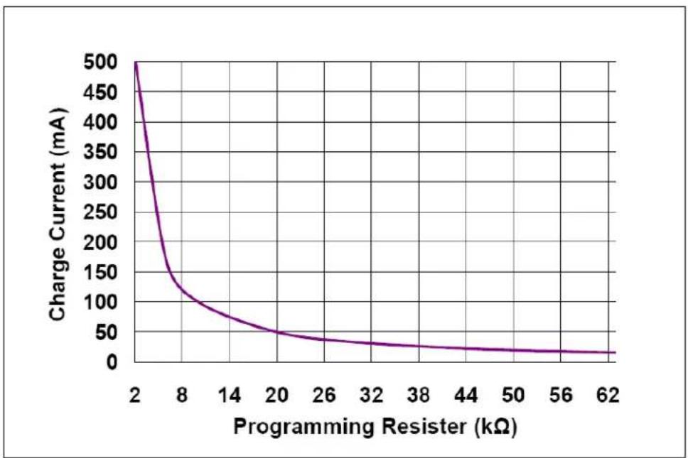
Note: Fast Charge Current can be programmed with various resistors that based on the Figure 2-1 and Figure 2-2.
Note: The Li-Ion battery pack can be replaced with test circuit or electronic load that can sink current with DC power supply. Please refer to Figure 2-3.
- Connected positive of load to System Load on the board and negative of load to either V_SS or V_BAT- . The load can be a power resistor or E-Load.
- Remove DC power supply, the load should be supported by the Li-Ion battery now.
Note: MCP73832 circuit is labeled "A" on the reference design while MCP73833 circuit is labeled "B" on the reference design.

line
| Programming Resistor (kΩ) | Charge Current (mA) | | ------------------------- | ------------------- | | 1 | 1000 | | 3 | 400 | | 5 | 200 | | 7 | 150 | | 9 | 100 | | 1 | 80 | | 1 | 60 | | 3 | 50 | | 1 | 40 | | 5 | 30 |FIGURE 2-1: MCP73833 Charge Current ( I_OUT ) vs. Programming Resistor ( R_PROG ).
line
| Programming Resister (kΩ) | Charge Current (mA) | | ------------------------- | ------------------- | | 2 | 500 | | 8 | 150 | | 14 | 100 | | 20 | 50 | | 26 | 30 | | 32 | 20 | | 38 | 15 | | 44 | 10 | | 50 | 8 | | 56 | 5 | | 62 | 3 |FIGURE 2-2: MCP73832 Charge Current (IOUT) vs. Programming Resistor ( R_PROG ).

flowchart
graph LR
    A["0V-6V Power Source"] --> B["Diode"]
    B --> C["Volt Meter"]
    C --> D["R 5Ω 10W"]
    D --> E["Amp Meter"]
    E --> F["Microchip Battery Charge Management Controller"]
    F --> G["VBAT+"]
    F --> H["VBAT-"]
    I["GND"] --> A
    J["1000 μF"] --> D
FIGURE 2-3: Simulated Battery Load.
text_image
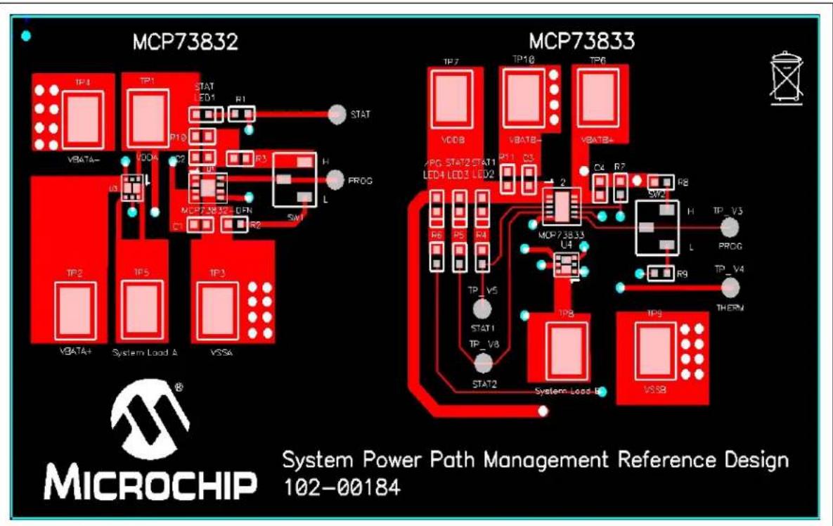
MCP73832 MCP73833 System Power Path Management Reference Design 102-00184 MICROCHIP VBA7A+ VBA7A+ VBA7A+ System Load A VSSA IP1 IP1 STAT LED1 R1 STAT VDDB VDA8- VDA8+ APG STAT2 STAT1 LED4 LED3 LED2 R11 R3 2 P4 R7 SW2 H TP_V5 PROG L TP_V6 R9 TP8 IP9 System Load B VSSBFIGURE 2-4: Board Top Assembly.
TABLE 2-1: MCP73833 CHARGE STATUS OUTPUTS
| CHARGE CYCLE STATE STAT1 (BLUE) | STAT2 (GREEN) | (RED) |
| Shutdown OFF OFF OFF | ||
| Standby OFF OFF ON | ||
| Charge in Progress ON OFF ON | ||
| Charge Complete (EOC) OFF ON ON | ||
| Temperature Fault OFF OFF ON | ||
| Timer Fault OFF OFF ON | ||
| System Test Mode | ON ON ON |
TABLE 2-2: MCP73832 CHARGE STATUS OUTPUTS
| CHARGE CYCLE STATE | STAT (BLUE) |
| Shutdown OFF | |
| No Battery Present | OFF |
| Preconditioning | ON |
| Constant-Current Fast Charge | ON |
| Constant Voltage | ON |
| Charge Complete - Standby | OFF |
Appendix A. Schematic and Layouts
A.1 INTRODUCTION
This appendix contains the following schematics and layouts for the Li-Ion Battery Charger System Power Path Management Reference Design:
- Board – Schematic
- Board – Top Layer
- Board – Top Metal Layer
- Board – Bottom Layer
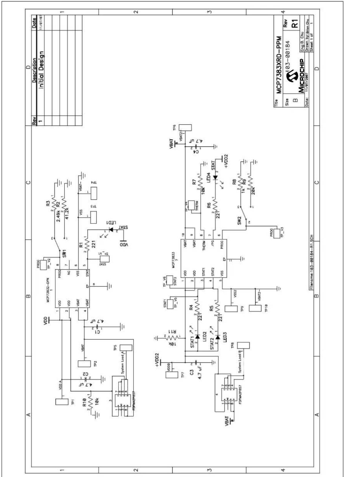
A.2 BOARD - SCHEMATIC
text_image
A B C D Rev Description Data 1 Initial Design 11/07/07 R10 2.49k R2 10k 4.7 uF PROG VDD A PROG VDD NC SW1 41.2k VBAT VBAT VSS VBAT EP STAT C1 2 2 4.7 uF STAT TP2 221 VDD:A VD System Load A PDFMA2P857 VDD VD VDD VD C2 2 TP5 4 +VDD2 VDDB 10k STAT1 TP_V6 MCP73833 TP7 1 C3 4.7 uF STAT1 VDD VBAT VBAT LED2 221 R4 STAT2 2 LED3 221 R5 TP8 1 System Load R VT10 VBAT2-VSP TP9 VSS2 TP10 VBAT2-VSP VDD STAT LED1 VDD VD VDD STAT2 VSS EP SW2 221 R8 TP_V3 VBAT TP6 THERM 10k R7 THERM 1PG LED4 STAT +VDD2 PROG PROG TP_V3 Title MCP7383XRD-PPM Size B MICROCHIP Rev R1 103-00184 Date: 11/07/2007 Drawn by: Brian Chu Filename:103-00184-R1.SCH Sheet 1 of 1 A B C DA.3 BOARD - TOP LAYER
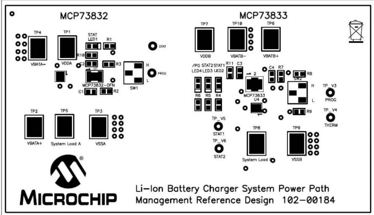
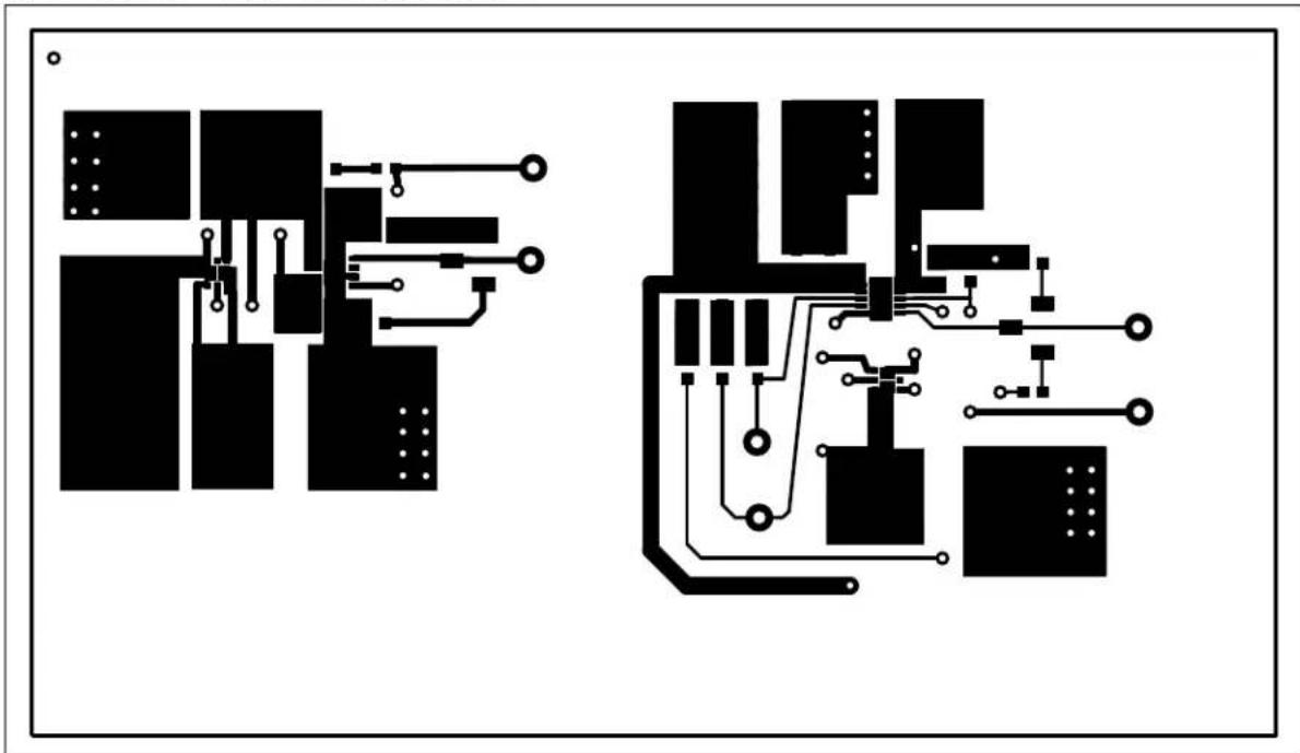
text_image
MCP73832 MCP73833 Li-Ion Battery Charger System Power Path Management Reference Design 102-00184 MICROCHIP VBITA- TP4 TP1 STAT LED1 R1 STAT VDDA VDDA R10 C2 U1 R3 SW1 H PROG L C1 MCP73832-DFN R2 TP2 TP5 TP3 VBATA+ System Load A VSSA TP7 TP10 TP6 VDDB VBATB- VBATB+ /PG STAT2 STAT1 LED4 LED3 LED2 R11 C3 2 C4 R7 SW2 R8 R6 R5 R4 MCP73833 U4 TP_V5 STAT1 TP_V6 STAT2 TP8 TP9 System Load I VSSB TP_V3 PROG L TP_V4 THERMA.4 BOARD - TOP METAL LAYER
natural_image
Pure electrical circuit lines without any symbolsA.5 BOARD - BOTTOM LAYER
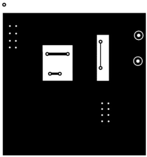
natural_image
Pure electrical circuit lines without any symbols
natural_image
Abstract black-and-white geometric pattern with white lines and dots, no text or symbols present1-V3A 48100-401
Appendix B. Bill Of Materials (BOM)
TABLE B-1: BILL OF MATERIALS (BOM)
| Qty | Reference | Description | Manufacture | Part Number | |
| 4 Bump | BUMPON HEMI | SPHERE .44X.20WHITE | 3M SJ5003-9-ND | ||
| 4 C1, | C2, C3, C4 CAP C | ERAMIC 4.7 uF 10 X5R 0603 Taiyo Yuden LMK107BJ475KA-T | |||
| 2 LED | 1, LED2 Blue Water Clear 0603 SMD LED Para Light USA | L-C191LBCT-U1 | |||
| 1 LED3 | True | Green Water Clear 0603 SMDLED | Para Light USA L-C191LGCT-U1 | ||
| 1 LED4 | Super | Red Water Clear 0603 SMDLED | Para Light USA L-C191KRCT-U1 | ||
| 1 | PCB | Printed Circuit Board | — | 104-00184-R1 | |
| 4 R1, | R4, R5, R6 RES 2 | 21 OHM 1/10W 1% 0603 SMD Panasonic® - ECG | ERJ-3EKF2210V | ||
| 1 R2 | RES | 41.2K OHM 1/10W 1% 0603SMD | Panasonic - ECG | ERJ-3EKF4122V | |
| 1 R3 | RES | 2.49K OHM 1/10W 1% 0603SMD | Panasonic - ECG | ERJ-3EKF2491V | |
| 3 | R7, R10, R11 | RES 10K OHM 1/10W 1% 0603 SMD | Panasonic - ECG | ERJ-3EKF1002V | |
| 1 | R8 | RES 1K OHM 1/10W 1% 0603 SMD | Panasonic - ECG | ERJ-3EKF1001V | |
| 1 | R9 | RES 20K OHM 1/10W 1% 0603 SMD | Panasonic - ECG | ERJ-3EKF2002V | |
| 2 | SW1, SW2 | SWITCH SLIDE SPDT SMD J-LEAD | Copal Electronics Inc | CJS-1200TA | |
| 10 | TP1, TP2, TP3,TP4, TP5, TP6,TP7, TP8, TP9,TP10 | PC Test Point Compact SMT | Keystone Electronics® | 5016 | |
| 1 U1 | Miniature Single Cell, Fully IntegratedLi-Ion, Li-Polymer Charge Manage-ment | Microchip Technology Inc | MCP73832-2ATI/MC | ||
| 1 U2 | Stand-Alone Linear Li-Ion / Li-PolymerCharge Management Controller | Microchip Technology Inc | MCP73833-AMI/MF | ||
| 2 U3, | U4 MOSFET/SCHOTTKY P-CHMICROFET2X2 | Fairchild Semiconductor® | FDFMA2P857 | ||
Note 1: The components listed in this Bill of Materials are representative of the PCB assembly. The released BOM used in manufacturing uses all RoHS-compliant components.
WORLDWIDE SALES AND SERVICE
AMERICAS
Corporate Office
2355 West Chandler Blvd.
Chandler, AZ 85224-6199
Tel: 480-792-7200
Fax: 480-792-7277
Technical Support:
http://support.microchip.com
Web Address:
www.microchip.com
Atlanta
Duluth, GA
Tel: 678-957-9614
Fax: 678-957-1455
Boston
Westborough, MA
Tel: 774-760-0087
Fax: 774-760-0088
Chicago
Itasca, IL
Tel: 630-285-0071
Fax: 630-285-0075
Dallas
Addison, TX
Tel: 972-818-7423
Fax: 972-818-2924
Detroit
Farmington Hills, MI
Tel: 248-538-2250
Fax: 248-538-2260
Kokomo
Kokomo, IN
Tel: 765-864-8360
Fax: 765-864-8387
Los Angeles
Mission Viejo, CA
Tel: 949-462-9523
Fax: 949-462-9608
Santa Clara
Santa Clara, CA
Tel: 408-961-6444
Fax: 408-961-6445
Toronto
Mississauga, Ontario,
Canada
Tel: 905-673-0699
Fax: 905-673-6509
ASIA/PACIFIC
Asia Pacific Office
Suites 3707-14, 37th Floor
Tower 6, The Gateway
Harbour City, Kowloon
Hong Kong
Tel: 852-2401-1200
Fax: 852-2401-3431
Australia - Sydney
Tel: 61-2-9868-6733
Fax: 61-2-9868-6755
China - Beijing
Tel: 86-10-8528-2100
Fax: 86-10-8528-2104
China - Chengdu
Tel: 86-28-8665-551
Fax: 86-28-8665-7889
China - Hong Kong SAR
Tel: 852-2401-1200
Fax: 852-2401-3431
China - Nanjing
Tel: 86-25-8473-2460
Fax: 86-25-8473-2470
China - Qingdao
Tel: 86-532-8502-7355
Fax: 86-532-8502-7205
China - Shanghai
Tel: 86-21-5407-5533
Fax: 86-21-5407-5066
China - Shenyang
Tel: 86-24-2334-2829
Fax: 86-24-2334-2393
China - Shenzhen
Tel: 86-755-8203-2660
Fax: 86-755-8203-1760
China - Wuhan
Tel: 86-27-5980-5300
Fax: 86-27-5980-5118
China - Xiamen
Tel: 86-592-2388138
Fax: 86-592-2388130
China - Xian
Tel: 86-29-8833-7252
Fax: 86-29-8833-7256
China - Zhuhai
Tel: 86-756-3210040
Fax: 86-756-3210049
ASIA/PACIFIC
India - Bangalore
Tel: 91-80-4182-8400
Fax: 91-80-4182-8422
India - New Delhi
Tel: 91-11-4160-8631
Fax: 91-11-4160-8632
India - Pune
Tel: 91-20-2566-1512
Fax: 91-20-2566-1513
Japan - Yokohama
Tel: 81-45-471-6166
Fax: 81-45-471-6122
Korea - Daegu
Tel: 82-53-744-4301
Fax: 82-53-744-4302
Korea - Seoul
Tel: 82-2-554-7200
Fax: 82-2-558-5932 or
82-2-558-5934
Malaysia - Kuala Lumpur
Tel: 60-3-6201-9857
Fax: 60-3-6201-9859
Malaysia - Penang
Tel: 60-4-227-8870
Fax: 60-4-227-4068
Philippines - Manila
Tel: 63-2-634-9065
Fax: 63-2-634-9069
Singapore
Tel: 65-6334-8870
Fax: 65-6334-8850
Taiwan - Hsin Chu
Tel: 886-3-572-9526
Fax: 886-3-572-6459
Taiwan - Kaohsiung
Tel: 886-7-536-4818
Fax: 886-7-536-4803
Taiwan - Taipei
Tel: 886-2-2500-6610
Fax: 886-2-2508-0102
Thailand - Bangkok
Tel: 66-2-694-1351
Fax: 66-2-694-1350
EUROPE
Austria - Wels
Tel: 43-7242-2244-39
Fax: 43-7242-2244-393
Denmark - Copenhagen
Tel: 45-4450-2828
Fax: 45-4485-2829
France - Paris
Tel: 33-1-69-53-63-20
Fax: 33-1-69-30-90-79
Germany - Munich
Tel: 49-89-627-144-0
Fax: 49-89-627-144-44
Italy - Milan
Tel: 39-0331-742611
Fax: 39-0331-466781
Netherlands - Drunen
Tel: 31-416-690399
Fax: 31-416-690340
Spain - Madrid
Tel: 34-91-708-08-90
Fax: 34-91-708-08-91
UK - Wokingham
Tel: 44-118-921-5869
Fax: 44-118-921-5820