MIC3223TE-BOOST - Electronic component Microchip - Free user manual and instructions
Find the device manual for free MIC3223TE-BOOST Microchip in PDF.

User questions about MIC3223TE-BOOST Microchip
0 question about this device. Answer the ones you know or ask your own.
Ask a new question about this device
Download the instructions for your Electronic component in PDF format for free! Find your manual MIC3223TE-BOOST - Microchip and take your electronic device back in hand. On this page are published all the documents necessary for the use of your device. MIC3223TE-BOOST by Microchip.
USER MANUAL MIC3223TE-BOOST Microchip
MIC3223 Evaluation Board
High-Power Boost LED Driver with Integrated FET
Bringing the Power to Light™
General Description
The MIC3223 is a constant-current boost switching controller specifically designed to power a string of high-power LEDs. The MIC3223 has an input voltage range from 4.5V to 20V and is ideal for a variety of applications. The MIC3223 evaluation board is designed to accommodate for a V_IN of 6V to 20V.
The MIC3223 utilizes an internal power device which offers a cost-conscious solution for driving high-power LED applications. Power consumption has been minimized through the implementation of a 200mV feedback-voltage reference providing an initial accuracy of ±5%. The MIC3223 controller is dimmable via a PWM input signal. An external FET (Q1) is in series with the LED string and is used to PWM Dim the LEDs. The MIC3223 also features an enable pin for low-power shutdown.
The LED current is regulated by keeping the voltage drop across the current-sense resistor (R5) constant. The LED current can be set by selecting the value of R5. In this version of the evaluation board, the output current is limited to 700mA. Table 1 provides a summary of the evaluation board specifications. The evaluation board schematic is shown in Figure 1 and the parts list is shown in the Bill of Materials table.
The switching frequency is fixed to 1MHz ±30%.
Requirements
- Voltage source capable of supplying 50 Watts
- Load: LED, resistive, or electronic load
- Scope
- Voltage meter
- (Optional) Function generator for PWM Dimming
How It Works
The MIC3223 evaluation board is set to operate as a boost converter, which requires the output voltage to be greater than the input voltage. It is important to have the series LED forward voltage drops be greater than the input voltage because when the converter is off the input is connected to the output through the inductor (L1) and diode (D1). V_IN is effectively applied across the LEDs and will turn on if the series sum of their forward voltage drop is not greater than V_IN . For 100% dimming duty-cycle, simply pull DIM IN to 5V. For a different LED current, change R5 using the following equation (when R5 is 0.56Ω and the LED current is equal to 0.35A):
$$ V _ {F B} = V _ {R E F L E D} = 1 \times R 5 $$
where V_REF = 0.2V
PWM Dimming
The PWM DIM signal applied to the DIM IN pin switches the current to the LEDs on and off. When DIM IN is high, the MIC3223 is enabled and the boost converter regulates the LED current by keeping the voltage drop across R5 constant. DIM IN also controls the DIM OUT pin. DIM OUT drives the gate of the external dimming FET (Q1). When DIM IN is high, DIM OUT is also high. When DIM IN is low, the converter turns off and the DIM OUT pin is low while driving the gate of Q1 low. When the gate of Q1 is low, Q1 turns off and the LED current stops.
Ordering Information
| Order Part Number Description | |
| MIC3223TE BOOST EV | Boost Evaluation Board |
MLF and MicroLeadFrame are registered trademarks of Amkor Technology, Inc.
Micrel Inc. • 2180 Fortune Drive • San Jose, CA 95131 • USA • tel +1 (408) 944-0800 • fax +1 (408) 474-1000 • http://www.micrel.com
Quick-Start Guide
- Connect a load (LED series string or resistive) between V_OUT and LED RTN (note that this is not the same as GND).
- Connect 12V (or other input voltage) to V_IN and GND.
-
Use a current probe to measure the load current and monitor the switch node with a scope to view the switch waveform.
-
PWM Dimming:
a. For no PWM dimming, connect the DIM IN terminal to the EN terminal. This is a convenient way to turn on and off the converter.
b. For PWM DIMMING, connect a function generator to the DIM IN input and GND (not LED RTN). Set the output at 0V – 5V square wave pulse at 100Hz – 20kHz. Make sure the pulse goes all the way to 0V.
Output Over-Voltage Protection (OVP)
The MIC3223 provides over-voltage protection (OVP) circuitry in order to protect the system from an over-voltage fault condition. This OVP threshold can be programmed through the use of external resistors (R3 and R4). A reference value of 1.245V is used for the OVP. The following equation can be used to calculate the resistor value for R3 to set the OVP point. Normally use 100k for R3:
$$ R 4 = \frac {R 3}{\text { OVP }} - 1 / 1. 2 4 5) (\mathrm{V} $$
On the evaluation board, these values have been set as follows: R4 = 3.24k and R3 = 100k and V_OVP = 40V .
Evaluation Board Design Specifications
| Parameter | Minimum | Typical | |
| V_IN | 6V | ||
| Output Voltage V | IN | 18-25 | 37V |
| Number of LEDs 7 9 | |||
| LED Current 0 | 0.2 – 0.5 | .7A | |
| Power Out 0 20W 15W | |||
| Efficiency | 90% | ||
| Switching Frequency (FIXED) | 1MHz | ||
| PWM Dim Frequency | 0 | 300Hz | 500Hz |
| Line Regulation | <5% | ||
| Load Regulation | <5% | ||
| Ambient Temperature | -40°C | +25°C | +85°C |
Maximum
Table 1. Evaluation Board Design Specifications
LED Current Selection
| R5 (Ω) | I_LED |
| 5 | 40mA |
| 2 | 100mA |
| 1 | 200mA |
| 0.62 | 320mA |
| 0.5 | 400mA |
| 0.56 | 350mA |
| 0.4 | 500mA |
| 0.28 | 700mA |
Table 2. LED Current Selection
Evaluation Board Schematic
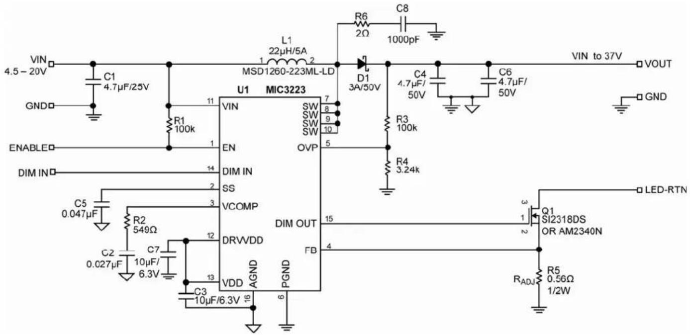
text_image
VIN 4.5 - 20V C1 4.7μF/25V GND ENABLE DIM IN C5 0.047μF R2 549Ω C2 0.027μF C7 10μF/ 6.3V R1 100k 11 VIN U1 MIC3223 SW SW SW SW SW EN DIM IN SS VCOMP DRVVDD VDD AGND PGND 12 13 16 15 FB 14 OVP 7 8 9 10 5 4 3 2 1 2 3 LED-RTN Q1 SI2318DS OR AM2340N R5 0.56Ω 1/2W R6 2Ω C8 1000pF D1 3A/50V C4 4.7μF/ 50V C6 4.7μF/ 50V VIN to 37V VOUT GNDBill of Materials
| Item | Part Number | Manufacturer | Description | ||
| C1 | GRM319R61E475KA12D | muRata^(1) | Ceramic Capacitor, 4.7μF, 25V, X7R, Size 1206 | 1 | |
| C3216X7R1E475M | TDK^(2) | ||||
| 12063D475KAT2A | AVX^(3) | ||||
| C2 | GRM188R71C273KA01D | muRata^(1) | Ceramic Capacitor, 0.027μF, 6.3V,X7R, Size 0603 | 1 | |
| C3, C7 | GRM188R60J106ME47D | muRata^(1) | Ceramic Capacitor, 10μF, 6.3V X7R, Size 0603 2 | ||
| C1608X5R0J106K | TDK^(2) | ||||
| 08056D106MAT2A | AVX^(3) | ||||
| C4, C6 | 12105C475KAZ2A | AVX^(3) | Ceramic Capacitor, 4.7μF, 50V, Size 1210, X7R 2 | ||
| GRM32ER71H475KA88L. | muRata^(1) | ||||
| C5 | GRM188R71C473KA01D | muRata^(1) | Ceramic Capacitor, 0.047μF, 6.3V,X7R, Size 0603 | 1 | |
| 0603YC473K4T2A | AVX^(3) | ||||
| C8 | GRM188R72A102KA37D | muRata^(1) Ceramic Capacitor, 1000pF, 100V, X7R 060 | |||
| D1 | SK35B | ^(4)SMOcky Diode, 3A, 50V (SMB) | 1 | ||
| L1 | MSD1260-223ML-LD | Colicraft | Inductor, 22μH, 5A | 1 | |
| R1, R3 | CRCW0603100KFKEA | Vishay Dale^(6) | Resistor, 100k, 1%, Size 0603 | 2 | |
| R2 | CRCW0603549RFKEA | Vishay Dale^(6) | Resistor, 549Ω, 1%, Size 0603 | 1 | |
| R4 | CRCW06033K24FKEA | Vishay Dale^(6) | Resistor, 3.24k, 1%, Size 0603 | 1 | |
| R5 | CRCW1206R560FKEA | Vishay Dale^(6) | Resistor, 0.56Ω, 1%, 1/2W, Size 1206 (for .35A LED current change for different ILED) | 1 | |
| R6 | RMC 1/4 2 1% R | SEI Stackpole Electronics, Inc. ^(7) | Resistor, 2Ω, 1%, 1/2W, Size 1210 | 1 | |
| Q1 | Si2318DS | Vishay Siliconix^(6) | N-Channel, 40V, MOSFET | 1 | |
| AM2340N | Analog Power^(8) | ||||
| U1 | MIC3223 | ^(8)Micrel, Inc. | High-Power Boost LED Driver with Integrated FET | 1 | |
Notes:
1. Murata: www.murata.com.
2. TDK: www.tdk.com.
3. AVX: www.avx.com.
4. MCC: www.mccsemi.com.
5. Coilcraft: www.coilcraft.com.
6. Vishay: www.vishay.com.
7. SEI Stackpole Electronics, Inc.: www.seielect.com.
8. Analog Power: www.analogpowerinc.com.
9. Micrel, Inc.: www.micrel.com.
PCB Layout Recommendations
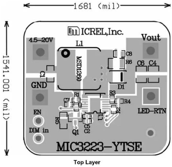
text_image
1681 (mil) ICREL,Inc. Vout 4.5-20V L1 MSD1360 C8 R6 C6 C4 GND D1 R1 R3 R4 EN DIM in Q1 Q5 U1 LED-RTN MIC3223-YTSE Top Layer 1541.001 (mil)
text_image
1681 (mil) ICREF1uc MCCCSS3-AL2E 408-844-0800 1541.001 (mil) BDO# 1S1J00-DL Bottom LayerPackage Information

text_image
PTN 1 ID MARK 1 2 3 E1 E Q N Q D e ATOP VIEW

text_image
DETAIL 'A' B/A B
text_image
0.25 SAGE PLANE R 01 L L1 RJ BEATING PLANE DETAIL 'A'
text_image
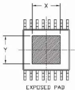
X Y EXPOSED PAD
text_image
A2 A SEATING PLANE A1 bEND VIEW
BOTTOM VIEW
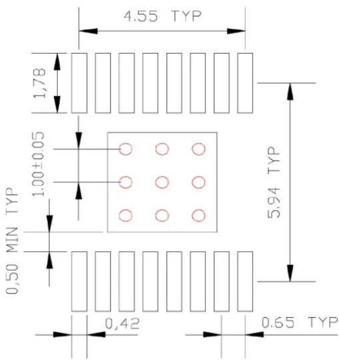
16-Pin EPAD TSSOP (TSE)
Recommended Land Pattern
LP # TSSOPEP-16LD-LP-1
All units are in mm
Tolerance ± 0.05 if not noted
text_image
4.55 TYP 1.78 1.00±0.05 MIN TYP 0.50 0.42 5.94 TYP 0.65 TYPRed circle indicates Thermal Via. Size should be .300-.350 mm in diameter and it should be connected to GND plane for maximum thermal performance.
MICREL, INC. 2180 FORTUNE DRIVE SAN JOSE, CA 95131 USA
TEL +1 (408) 944-0800 FAX +1 (408) 474-1000 WEB http://www.micrel.com
The information furnished by Micrel in this data sheet is believed to be accurate and reliable. However, no responsibility is assumed by Micrel for its use. Micrel reserves the right to change circuitry and specifications at any time without notification to the customer.
Micrel Products are not designed or authorized for use as components in life support appliances, devices or systems where malfunction of a product can reasonably be expected to result in personal injury. Life support devices or systems are devices or systems that (a) are intended for surgical implant into the body or (b) support or sustain life, and whose failure to perform can be reasonably expected to result in a significant injury to the user. A Purchaser's use or sale of Micrel Products for use in life support appliances, devices or systems is a Purchaser's own risk and Purchaser agrees to fully indemnify Micrel for any damages resulting from such use or sale.
© 2010 Micrel, Incorporated.