MIC2297-42YML - Electronic component Microchip - Free user manual and instructions
Find the device manual for free MIC2297-42YML Microchip in PDF.

User questions about MIC2297-42YML Microchip
0 question about this device. Answer the ones you know or ask your own.
Ask a new question about this device
Download the instructions for your Electronic component in PDF format for free! Find your manual MIC2297-42YML - Microchip and take your electronic device back in hand. On this page are published all the documents necessary for the use of your device. MIC2297-42YML by Microchip.
USER MANUAL MIC2297-42YML Microchip
MIC2297 Evaluation Board
600kHz 42V OVP PWM White LED Driver
General Description
The MIC2297 is a 600kHz PWM White LED Driver optimized for 6 to 10 series WLEDs. With an output voltage of up to 42V and a guaranteed 1.2A on the internal power switch, the MIC2297 can easily drive 10 WLEDs at 20mA continuous current. The MIC2297 features WLED brightness control using the BRT pin and has output over voltage protection (OVP) to protect the device in case the WLEDs are disconnected unexpectedly. Available in a tiny 10-pin 2.5mm x 2.5mm x 0.85mm MLF ^® package, the MIC2297 solution only requires a total of 6 external components.
The MIC2297 operates at a default (BRT pin is open) feedback voltage of only 200mV. The low feedback voltage reduces the power dissipation from the external current set resistor and increases total operating efficiency.
When brightness control is required, the MIC2297 features brightness control by applying a DC voltage to the BRT pin. When applying a DC voltage to the BRT pin, the feedback voltage is equal to the BRT voltage divided by 5. This feature essentially increases or decreases the feedback voltage from its default value (200mV), changing the WLED current to control the WLED brightness.
Alternatively, a PWM signal may also be applied to the BRT pin for brightness control. When a PWM signal (1kHz recommended) is applied to the BRT pin, the WLEDs are dimmed depending on the duty cycle and the peak voltage of the signal. The PWM frequency can range from 1kHz to 1MHz. The selected PWM frequency does not affect the WLED brightness. Assuming a 1V PWM signal is applied, as the duty cycle decreases, the feedback voltage decreases, thus reducing the WLED current.
Requirements
The MIC2297 evaluation board requires an input power source that is capable of delivering greater than 1.2A at 2.5V.
Precautions
The evaluation board does not have reverse polarity protection. Applying a negative voltage to the V_IN terminal may damage the device.
The MIC2297 evaluation board is tailored for a single or dual Li-Ion input source. The input voltage should never exceed 10V.
Getting Started
-
Connect an external supply to V_IN . Apply desired input voltage to the V_IN (J1) and ground (J4) terminals of the evaluation board, paying careful attention to polarity and supply voltage (2.5V ≤ V_IN ≤ 10V). An ammeter may be placed between the input supply and the V_IN (J1) terminal to the evaluation board to accurately monitor the input current. The ammeter and/or power lead resistance can reduce the voltage supplied to the input; therefore, the supply voltage at the V_IN (J1) terminal should be monitored.
-
Enable/Disable the MIC2297. To enable the MIC2297, apply a 1.5V or greater voltage signal to the EN (J2) terminal. To disable the device, pull the EN (J2) pin below 0.4V. The evaluation board is configured with a jumper (JP1) from V_IN to the enable pin and a 10k pull-down resistor to ground to conveniently turn the part on or off. Connecting the jumper (JP1) will enable the MIC2297, while removing the jumper will disable the part.
-
DCV Brightness Control. To control the brightness with a DC voltage, see the DVC Brightness Control section.
-
PWM Brightness Control. To control the brightness with a PWM Signal, see the PWM Brightness Control section.
Note: For detailed specifications, please refer to the MIC2297 Datasheet at www.micrel.com.
Ordering Information
| Part Number Description | |
| MIC2297-42YML EV | Evaluation board with the MIC2297 42V device |
MLF and MicroLeadFrame are registered trademarks of Amkor Technology, Inc.
Micrel Inc. • 2180 Fortune Drive • San Jose, CA 95131 • USA • tel +1 (408) 944-0800 • fax + 1 (408) 474-1000 • http://www.micrel.com
LED Current Setting
There are 10 WLEDs provided with the evaluation board. Two of the WLEDs (D1 and D2) may be by-passed by placing a jumper on JP3. The WLED current ( I_LED ) is equal to the feedback voltage ( V_FB = 200mV by default) divided by the R3 resistance value. The evaluation board is provided with R3 equal to 10Ω. The brightness level is proportional to I_LED . Programming the feedback voltage changes the I_LED , therefore changing the brightness level.
$$ I _ {L E D} = V _ {F B} / R 3 \tag {1} $$
DCV Brightness Control
The brightness level can be set by applying a DC voltage (BRT) to the BRT pin. When a DC voltage is applied to the BRT pin, the feedback voltage is changed from the default value of 200mV to:
$$ V _ {F B} = B R T / 5 \tag {2} $$
Assuming BRT equals 1V, then V_FB will be 200mV and ILED may be calculated by:
$$ I _ {L E D} = V _ {F B} / R 3 $$
$$ I _ {L E D} = 2 0 0 \mathrm{mV} / 1 0 \Omega $$
$$ I _ {L E D} = 2 0 \mathrm{mA} $$
Similarly, if BRT equals 2V, then V_FB will be 400mV and the I_LED may be calculated by:
$$ I _ {L E D} = V _ {F B} / R 3 $$
$$ I _ {L E D} = 4 0 0 \mathrm{mV} / 1 0 \Omega $$
$$ I _ {L E D} = 4 0 \mathrm{mA} $$
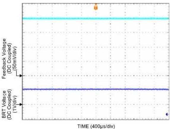
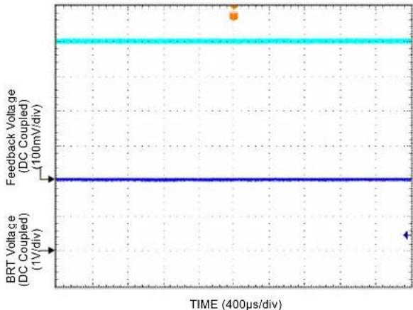
The feedback voltage can be changed using the BRT pin. Changing the feedback voltage changes the WLED current, which will change the WLED brightness. Refer to the Figure 1 and Figure 2 for reference.
line
| TIME (400μs/div) | Feedback Voltage (DC Coupled) | BRT Voltage (DC Coupled) | | ---------------- | ----------------------------- | ------------------------ | | 0 | 50mV/div | 1V/div |Figure 1. BRT = 1V, VFB = 200mV, ILED = 20mA
line
| TIME (400μs/div) | Feedback Voltage (DC Coupled) (100mV/div) | BRT Voltage (DC Coupled) (1V/div) | | ---------------- | ---------------------------------------- | --------------------------------- | | 0 | 100 | 1 | | 400 | 100 | 1 |Figure 2. BRT = 2V, VFB = 400mV, ILED = 40mA
PWM Brightness Control
The brightness level can also be set by applying a PWM signal to the BRT pin. To calculate the feedback voltage when a PWM signal is applied to the BRT pin, use the following formula:
$$ V _ {F B} = V _ {P E A K} / 5 * D \tag {3} $$
V_PEAK is the peak of the PWM voltage and D is the duty cycle. If V_PEAK is 1V and the duty cycle is 1%, then V_FB can be calculated by:
$$ V _ {F B} = 1 V / 5 ^ {*} 0. 0 1 $$
$$ V _ {F B} = 2 m V $$
The I_LED can then be calculated by:
$$ I _ {L E D} = V _ {F B} / R 3 $$
$$ I _ {L E D} = 2 \mathrm{mV} / 1 0 \Omega $$
$$ I _ {L E D} = 2 0 0 \mu A $$
Similarly, if the V_PEAK is 1V and the duty cycle is 50%, then V_FB can be calculated by:
$$ V _ {F B} = 1 V / 5 ^ {*} 0. 5 $$
$$ V _ {F B} = 1 0 0 \mathrm{mV} $$
The I_LED can then be calculated by:
$$ I _ {L E D} = V _ {F B} / R 3 $$
$$ I _ {L E D} = 1 0 0 \mathrm{mV} / 1 0 \Omega $$
$$ I _ {L E D} = 1 0 \mathrm{mA} $$
With PWM brightness control, the MIC2297 has great versatility since brightness may be set anywhere from 0 to 100 percent. Refer to the following figures for reference.

line
| TIME (400μs/div) | Feedback Voltage (DC Coupled) (10mV/div) | BRT Voltage (DC Coupled) (1V/div) | | ---------------- | ---------------------------------------- | --------------------------------- | | 0 | 0 | 0 | | 400 | 0 | 0 | | 500 | 0 | 0 | | 600 | 0 | 0 | | 700 | 0 | 0 | | 800 | 0 | 0 | | 900 | 0 | 0 | | 1000 | 0 | 0 | | 1100 | 0 | 0 | | 1200 | 0 | 0 | | 1300 | 0 | 0 | | 1400 | 0 | 0 | | 1500 | 0 | 0 | | 1600 | 0 | 0 | | 1700 | 0 | 0 | | 1800 | 0 | 0 | | 1900 | 0 | 0 | | 2000 | 0 | 0 | | 2100 | 0 | 0 | | 2200 | 0 | 0 | | 2300 | 0 | 0 | | 2400 | 0 | 0 | | 2500 | 0 | 0 | | 2600 | 0 | 0 | | 2700 | 0 | 0 | | 2800 | 0 | 0 | | 2900 | 0 | 0 | | 3000 | 0 | 0 | | 3100 | 0 | 0 | | 3200 | 0 | 0 | | 3300 | 0 | 0 | | 3400 | 0 | 0 | | 3500 | 0 | 0 | | 3600 | 0 | 0 | | 3700 | 0 | 0 | | 3800 | 0 | 0 | | 3900 | 0 | 0 | | 4000 | 0 | 0 | | 4100 | 0 | 0 | | 4200 | 0 | 0 | | 4300 | 0 | 0 | | 4400 | 0 | 0 | | 4500 | 0 | 0 | | 4600 | 0 | 0 | | 4700 | 0 | 0 | | 4800 | 0 | 0 | | 4900 | 0 | 0 | | 5000 | 0 | 0 | | Note: The actual values for Feedback Voltage and BRT Voltage are not provided in the code. The actual values are generated by the OCR result 'DC Coupled' and 'DC Div', respectively. There is no label data provided in the code.Figure 3. Duty Cycle = 1%, V_FB = 2mV, I_LED = 200μA

line
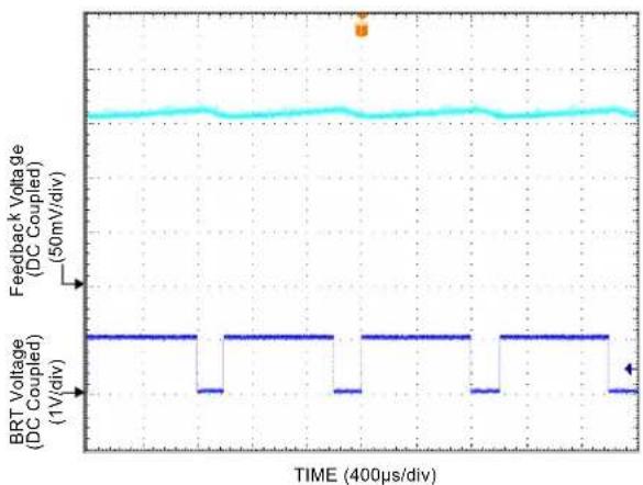
| TIME (400μs/div) | BRT Voltage (DC Coupled) (1V/div) | Feedback Voltage (DC Coupled) (50mV/div) | | ---------------- | ---------------------------------- | ---------------------------------------- | | 0 | 0 | 50 | | 100 | 0 | 50 | | 200 | 0 | 50 | | 300 | 0 | 50 | | 400 | 0 | 50 | | 500 | 0 | 50 | | 600 | 0 | 50 | | 700 | 0 | 50 | | 800 | 0 | 50 | | 900 | 0 | 50 | | 1000 | 0 | 50 | | 1100 | 0 | 50 | | 1200 | 0 | 50 | | 1300 | 0 | 50 | | 1400 | 0 | 50 | | 1500 | 0 | 50 | | 1600 | 0 | 50 | | 1700 | 0 | 50 | | 1800 | 0 | 50 | | 1900 | 0 | 50 | | 2000 | 0 | 50 | | 2100 | 0 | 50 | | 2200 | 0 | 50 | | 2300 | 0 | 50 | | 2400 | 0 | 50 | | 2500 | 0 | 50 | | 2600 | 0 | 50 | | 2700 | 0 | 50 | | 2800 | 0 | 50 | | 2900 | 0 | 50 | | 3000 | 0 | 50 | | 3100 | 0 | 50 | | 3200 | 0 | 50 | | 3300 | 0 | 50 | | 3400 | 0 | 50 | | 3500 | 0 | 50 | | 3600 | 0 | 50 | | 3700 | 0 | 50 | | 3800 | 0 | 50 | | 3900 | 0 | 50 | | 4000 | 0 | 50 |Figure 4. Duty Cycle = 20%, V_FB = 40mV, I_LED = 4mA
line
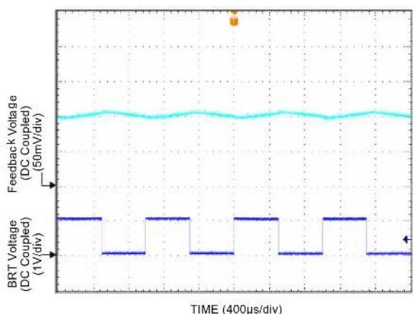
| TIME (400μs/div) | Feedback Voltage (DC Coupled) (50mV/div) | BRT Voltage (DC Coupled) (1V/div) | | ---------------- | ---------------------------------------- | --------------------------------- | | 0 | ~50 | 1 | | 100 | ~50 | 1 | | 200 | ~50 | 1 | | 300 | ~50 | 1 | | 400 | ~50 | 1 | | 500 | ~50 | 1 | | 600 | ~50 | 1 | | 700 | ~50 | 1 | | 800 | ~50 | 1 | | 900 | ~50 | 1 | | 1000 | ~50 | 1 | | 1100 | ~50 | 1 | | 1200 | ~50 | 1 | | 1300 | ~50 | 1 | | 1400 | ~50 | 1 | | 1500 | ~50 | 1 | | 1600 | ~50 | 1 | | 1700 | ~50 | 1 | | 1800 | ~50 | 1 | | 1900 | ~50 | 1 | | 2000 | ~50 | 1 | | 2100 | ~50 | 1 | | 2200 | ~50 | 1 | | 2300 | ~50 | 1 | | 2400 | ~50 | 1 | | 2500 | ~50 | 1 | | 2600 | ~50 | 1 | | 2700 | ~50 | 1 | | 2800 | ~50 | 1 | | 2900 | ~50 | 1 | | 3000 | ~50 | 1 | | 3100 | ~50 | 1 | | 3200 | ~50 | 1 | | 3300 | ~50 | 1 | | 3400 | ~50 | 1 | | 3500 | ~50 | 1 | | 3600 | ~50 | 1 | | 3700 | ~50 | 1 | | 3800 | ~50 | 1 | | 3900 | ~50 | 1 | | 4000 | ~50 | 1 | | 4100 | ~50 | 1 | | 4200 | ~50 | 1 | | 4300 | ~50 | 1 | | 4400 | ~50 | 1 | | 4500 | ~50 | 1 | | 4600 | ~50 | 1 | | 4700 | ~50 | 1 | | 4800 | ~50 | 1 | | 4900 | ~50 | 1 | | 5000 | ~50 | 1 | | 5100 | ~50 | 1 | | 5200 | ~50 | 1 | | 5300 | ~50 | 1 | | 5400 | ~50 | 1 | | 5500 | ~50 | 1 | | 5600 | ~50 | 1 | | 5700 | ~50 | 1 | | 5800 | ~50 | 1 | | 5900 | ~50 | 1 | | 6000 | ~50 | 1 | | 6100 | ~50 | 1 | | 6200 | ~50 | 1 | | 6300 | ~50 | 1 | | 6400 | ~50 | 1 | | 6500 | ~50 | 1 | | 6600 | ~50 | 1 | | 6700 | ~50 | 1 | | 6800 | ~50 | 1 | | 6900 | ~50 | 1 | | 7000 | ~50 | 1 | | 7100 | ~50 | 1 | | 7200 | ~50 | 1 | | 7300 | ~50 | 1 | | 7400 | ~50 | 1 | | 7500 | ~50 | 1 | | 7600 | ~50 | 1 | | 7700 | ~50 | 1 | | 7800 | ~50 | 1 | | 7900 | ~50 | 1 | | 8000 | ~50 | 1 | | 8100 | ~50 | 1 | | 8200 | ~50 | 1 | | 8300 | ~50 | 1 | | 8400 | ~50 | 1 | | 8500 | ~50 | 1 | | 8600 | ~50 | 1 | | 8700 | ~50 | 1 | | 8800 | ~50 | 1 | | 8900 | ~50 | 1 | | 9000 | ~50 | 1 | | 9100 | ~50 | 1 | | 9200 | ~50 | 1 | | 9300 | ~50 | 1 | | 9400 | ~50 | 1 | | 9500 | ~50 | 1 | | 9600 | ~50 | 1 | | 9700 | ~50 | 1 | | 9800 | ~50 | 1 | | 9900 | ~50 | 1 | | 12/2/2/2/2/2/2/2/2/2/2/2/2/2/2/2/2/2/2/2/2/2/2/2/2/2/2/2/2/2/2/2/2/2/2/2/2/2/2/2/2/2/2/2/2/2/2/2/2/2/2 / nan / nan / nan / nan / nan / nan / nan / nan / nan / nan / nan / nan / nan / nan / nan / nan / nan / nan / nan / nan / nan / nan / nan / nan / nan / nan / nan / nan / nan / nan / nan / nan / nan / nan / nan / nan / nan / nan / nan / nan / nan nan nan nan nan nan nan nan nan nan nan nan nan nan nan nan nan nan nan nan nan nan nan nan nan nan nan nan nan nan nan nan nan nan nan nan nan nan nan nan nan nan nan nan nan nan nan nan nan nan nan nan nan nan nan nan nan nan nan nan nan nan nan nan nan nan nan NanFigure 5. Duty Cycle = 50%, V_FB = 100mV, I_LED = 10mA
line
| TIME (400μs/div) | Feedback Voltage (DC Coupled) (50mV/div) | BRT Voltage (DC Coupled) (1V/div) | | ---------------- | ---------------------------------------- | --------------------------------- | | 0 | ~0.8 | 0 | | 100 | ~0.8 | 0 | | 200 | ~0.8 | 0 | | 300 | ~0.8 | 0 | | 400 | ~0.8 | 0 | | 500 | ~0.8 | 0 | | 600 | ~0.8 | 0 | | 700 | ~0.8 | 0 | | 800 | ~0.8 | 0 | | 900 | ~0.8 | 0 | | 1000 | ~0.8 | 0 | | 1100 | ~0.8 | 0 | | 1200 | ~0.8 | 0 | | 1300 | ~0.8 | 0 | | 1400 | ~0.8 | 0 | | 1500 | ~0.8 | 0 | | 1600 | ~0.8 | 0 | | 1700 | ~0.8 | 0 | | 1800 | ~0.8 | 0 | | 1900 | ~0.8 | 0 | | 2000 | ~0.8 | 0 | | 2100 | ~0.8 | 0 | | 2200 | ~0.8 | 0 | | 2300 | ~0.8 | 0 | | 2400 | ~0.8 | 0 | | 2500 | ~0.8 | 0 | | 2600 | ~0.8 | 0 | | 2700 | ~0.8 | 0 | | 2800 | ~0.8 | 0 | | 2900 | ~0.8 | 0 | | 3000 | ~0.8 | 0 | | 3100 | ~0.8 | 0 | | 3200 | ~0.8 | 0 | | 3300 | ~0.8 | 0 | | 3400 | ~0.8 | 0 | | 3500 | ~0.8 | 0 | | 3600 | ~0.8 | 0 | | 3700 | ~0.8 | 0 | | 3800 | ~0.8 | 0 | | 3900 | ~0.8 | 0 | | 4000 | ~0.8 | 0 | | 4100 | ~0.8 | 0 | | 4200 | ~0.8 | 0 | | 4300 | ~0.8 | 0 | | 4400 | ~0.8 | 0 | | 4500 | ~0.8 | 0 | | 4600 | ~0.8 | 0 | | 4700 | ~0.8 | 0 | | 4800 | ~0.8 | 0 | | 4900 | ~0.8 | 0 | | 5000 | ~0.8 | 0 | | 5100 | ~1.5 | -1V/Div | | 5200 | -1V/Div | -1V/Div | | 5300 | -1V/Div | -1V/Div | | 5400 | -1V/Div | -1V/Div | | 5500 | -1V/Div | -1V/Div | | 5600 | -1V/Div | -1V/Div | | 5700 | -1V/Div | -1V/Div | | 5800 | -1V/Div | -1V/Div | | 5900 | -1V/Div | -1V/Div | | 6000 | -1V/Div | -1V/Div | | 6100 | -1V/Div | -1V/Div | | 6200 | -1V/Div | -1V/Div | | 6300 | -1V/Div | -1V/Div | | 6400 | -1V/Div | -1V/Div | | 6500 | -1V/Div | -1V/Div | | 6600 | -1V/Div | -1V/Div | | 6700 | -1V/Div | -1V/Div | | 6800 | -1V/Div | -1V/Div | | 6900 | -1V/Div | -1V/Div | | 7000 | -1V/Div | -1V/Div | | 7100 | -1V/Div | -1V/Div | | 7200 | -1V/Div | -1V/Div | | 7300 | -1V/Div | -1V/Div | | 7400 | -1V/Div | -1V/Div | | 7500 | -1V/Div | -1V/Div | | 7600 | -1V/Div | -1V/Div | | 7700 | -1V/Div | -1V/Div | | 7800 | -1V/Div | -1V/Div | | 7900 | -1V/Div | -1V/Div | | 8000 | -1V/Div | -1V/Div | | 8100 | -1V/Div | -1V/Div | | 8200 | -1V/Div | -1V/Div | | 8300 | -1V/Div | -1V/Div | | 8400 | -1V/Div | -1V/Div | | 8500 | -1V/Div | -1V/Div | | 8600 | -1V/Div | -1V/Div | | 8700 | -1V/Div | -1V/Div | | 8800 | -1V/Div | -1V/Div | | 8900 | -1V/Div | -1V/Div | | 9000 | -1V/Div | -1V/Div | | 9100 | -1V/Div | -1V/Div | | 9200 | -1V/Div | -1V/Div | | 9300 | -1V/Div | -1V/Div | | 9400 | -1V/Div | -1V/Div | | 9500 | -1V/Div | -1V/Div | | 9600 | -1V/Div | -1V/Div | | 9700 | -1V/Div | -1V/Div | | 9800 | -1V/Div | -1V/Div | | 9900 | -1V/Div | -1V/Div | | 12E-2 | ~-2 | ~-2 | | (Note: The data is extracted from the code and is not provided in the output format for the rest of the chart). The output format is labeled as 'Feedback Voltage (DC Coupled)' and 'BRT Voltage (DC Coupled)' respectively.Figure 6. Duty Cycle = 80%, V_FB = 160mV, I_LED = 16mA
In Figure 7, when the duty cycle is equal to 100%, D equals 1. When we set D equal to 1 in equation (3), notice (3) becomes the same as equation (2), if we assume V_PEAK equals BRT. Using a 100% duty cycle is the same as applying a constant DC voltage to the BRT pin. In this instance, Figure 7 is exactly the same as Figure 1.

line
| TIME (400μs/div) | Feedback Voltage (DC Coupled) (50mV/div) | BRT Voltage (DC Coupled) (1V/div) | | ---------------- | ---------------------------------------- | --------------------------------- | | 0 | 50 | 1 | | 200 | 50 | 1 | | 400 | 50 | 1 |Figure 7. Duty Cycle = 100%, V_FB = 200mV, I_LED = 20mA
Typical Application Circuit
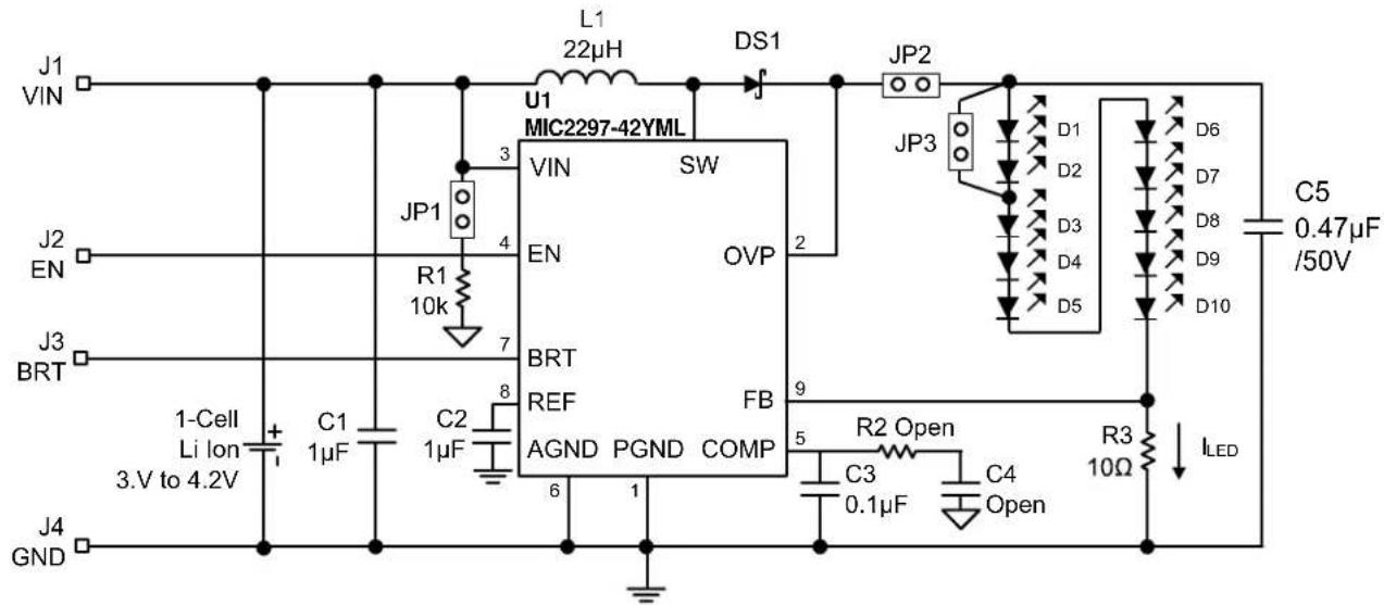
text_image
J1 VIN U1 22µH L1 DS1 JP2 MIC2297-42YML 3 VIN SW EN OVP 2 JP3 D1 D2 D3 D4 D5 D6 EN R1 10k 7 BRT REF FB AGND PGND COMP 9 R2 Open 5 C3 0.1µF C4 Open R3 10Ω ILED C5 0.47µF /50V J2 J3 BRT 1-Cell Li lon + - 3.V to 4.2V C1 1µF C2 1µF J4 GND10 LED Configuration
Bill of Materials
| Item | Part Number | Manufacturer | Description | |
| C1, C2 | C1608X5R1A105K TDK | ^(1) 1μF Ceramic Capacitor, 10V, X5R, Size 0603 2 | ||
| C3 | VJ0603Y104KXXAT | ^(2) Vishay Ceramic Capacitor, 25V, X7R, Size 0603 1 | ||
| C4 | Open | |||
| C5 | C2012X7R1H474M | ^(1) 0.4TJK Ceramic Capacitor, 50V, X7R, Size 0805 1 | ||
| DS1 | DFLS160-7 | Diodes Inc ^(3) | 1A, 60V, Schottky Diode | 1 |
| L1 | LQH43CN220K01L | Murata ^(4) | 22μH, 420mA ISAT., 120mΩ, (4.5mm × 3.2mm × 2.6mm) | 1 |
| MLP3225S100L | TDK ^(1) 10μH, 1000mA I SAT., 130mΩ, (3.2mm × 2.5mm × 1mm) | |||
| LPS4012-223MLC | Coilcraft ^(5) | 22μH, 720mA ISAT., 600mΩ, (4.1mm × 4.1mm × 1.2mm) | ||
| R1 | CRCW06031002FRT1 | ^(2) Vishay 10KΩ, 1%, 1/16W, Size 0603 | 1 | |
| R2 | Open | |||
| R3 | CRCW060310R0FRT1 | ^(2) Vishay 10Ω, 1%, 1/16W, Size 0603 | 1 | |
| D1-D10 | VLMW3100-5K8L-08 | Vishay ^(2) 20mA Standard SMD LED PLCC-2 | 10 | |
| U1 | MIC2297-42YML | Micrel ^(6) | 600kHz 40V PWM White LED Driver | 1 |
-
TDK: www.tdk.com
-
Vishay-Dale: www.vishay.com
-
Diodes Inc: www.diodes.com
-
Murata: www.murata.com
-
Coilcraft: www.coilcraft.com
-
Micrel, Inc: www.micrel.com
PCB Layout Recommendations

text_image
ICREL.Inc 408-944-0800 MIC2297-YML V1n J1 JP1 EN BRT GND J3 R1 C4 D1 JP2 D2 JP3 D10 DS1 DS2 D3 J4 830 (mil) 870 (mil) White LED Driver. 1600 (mil) 1600.008 (mil) Top Layer
text_image
1600 (mil) ICER.IUC 0080-44E-80F JMYCSE5-JMY 830 (mil) 1600.008 (mil) 870 (mil) Bottom Layer 015508-TO 2HoR O1rPer2 O1rPer2 TO-80SS10MICREL, INC. 2180 FORTUNE DRIVE SAN JOSE, CA 95131 USA
TEL +1 (408) 944-0800 FAX +1 (408) 474-1000 WEB http://www.micrel.com
The information furnished by Micrel in this data sheet is believed to be accurate and reliable. However, no responsibility is assumed by Micrel for its use. Micrel reserves the right to change circuitry and specifications at any time without notification to the customer.
Micrel Products are not designed or authorized for use as components in life support appliances, devices or systems where malfunction of a product can reasonably be expected to result in personal injury. Life support devices or systems are devices or systems that (a) are intended for surgical implant into the body or (b) support or sustain life, and whose failure to perform can be reasonably expected to result in a significant injury to the user. A Purchaser's use or sale of Micrel Products for use in life support appliances, devices or systems is a Purchaser's own risk and Purchaser agrees to fully indemnify Micrel for any damages resulting from such use or sale.
© 2008 Micrel, Incorporated.