HV816DB2 - Electronic board Microchip - Free user manual and instructions
Find the device manual for free HV816DB2 Microchip in PDF.

User questions about HV816DB2 Microchip
0 question about this device. Answer the ones you know or ask your own.
Ask a new question about this device
Download the instructions for your Electronic board in PDF format for free! Find your manual HV816DB2 - Microchip and take your electronic device back in hand. On this page are published all the documents necessary for the use of your device. HV816DB2 by Microchip.
USER MANUAL HV816DB2 Microchip
High Brightness 10in ^2 EL Lamp Driver Demoboard
General Description
The Supertex HV816DB2 is a high brightness demoboard with the circuitry to drive a 10in² EL lamp using the HV816 in a 4x4 QFN-16 package.
Simply connect the board to a power supply and an EL lamp as shown in the circuit schematic on the following page. The HV816DB2 circuit has been optimized to drive an EL lamp size of 10in^2 . For different EL frequencies or smaller EL lamps sizes, the demoboard can be re-optimized by changing some of the component values.
The output voltage is typically ±180V for high lamp brightness, using a single supply input voltage of 5.0V. An external N-channel MOSFET, Supertex TN2425 is used to boost the output voltage to a nominal value of 180V with an input voltage of 5.0V.
For split supply applications, the diode BAS20 between VIN and VDD has to be removed so separate supplies can be used for VIN and VDD.
The discharge rate on the output for EL lamp can be adjusted to minimize audible noise. By increasing the value of the
R_SLEW resistor, the discharge rate will increase, which will reduce audible noise but will also reduce brightness. R_SLEW can be set to a value between 100kΩ and 500kΩ with 100kΩ for maximum brightness.
The HV816DB2 has the provision to set the EL lamp frequency using the resistor R_EL on the board or by an external clock input at the S_EL pin. To use an external clock input, the REL resistor should be removed and the REL-Osc pin should be connected to GND.
| Specifications | |
| V_DD input voltage 2.7 to 5.5V | |
| V_IN inductor supply voltage 4.5 to 5.0V | |
| Typical supply current 150mA | |
| Lamp size 10in | 2 |
| Lamp frequency 190Hz | |
| Converter frequency 150kHz | |
| Board dimensions 27mm x 27mm | |
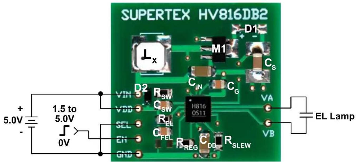
Board Layout and Connection Diagram
text_image
SUPERTEX HV816DB2 D1 M1 Cs Lx CIN Cg D2 VIN Rsw VDD Csw H816 OS11 VA SEL REL CFL EN RREG CDD RSLEW VB EL Lamp + 5.0V - 1.5 to 5.0V 0VConnections:
VIN, Input
Inductor input voltage. Single supply can be used for V_IN and V_DD or separate supplies can be used. If separate supplies are used, the diode BAS20 between VIN and VDD has to be removed. The input range for V_IN is 4.5 to 5.0V.
VDD, Input
Device input voltage. Single supply can be used for V_IN and V_DD or separate supplies can be used. If separate supplies are used, the diode BAS20 between VIN and VDD has to be removed. The input range for V_DD is 2.7 to 5.5V.
GND
Device Ground. Connect to power supply ground.
EN, Input
A CMOS logic input which enables/disables the lamp driver. A logic high (1.5V to V_DD ) enables the driver and a logic low (0 to 0.2V) disables the driver.
SEL, Input
CMOS logic input to set the EL frequency. To use this pin, the REL-Osc pin should be connected to GND. The frequency input at this pin should be 4x the desired output frequency. An external CLK signal can be used for this input. If this pin is not used, it should be connected to ground.
VA and VB Outputs
VA and VB are for EL Lamp connections. They should be connected to an EL lamp. Polarity is irrelevant.
HV816DB2 Circuit Schematic

text_image
V_IN = 5.0V D2 BAS20 C_IN 100μF Lx LPS5030-473ML M1 TN2425N8 D1 ES1D C_S 3.3nF 200V NPO C_G 100nF 14 15 6 16 VDRIVE GATE U1 HV816K6-G VDD RSW-Osc CS 12 R_SW = 590kΩ 1 VDD R_EL = 1.0MΩ 2 REL-Osc VA C_DD 100μF C_SW 100nF C_FEL 100nF 4 VREG VB 3 VOUT SEL EN = 1.5V to V_DD R_REG 100kΩ 5 9 HVGND GND RSLEW-OUT 13 Backside Slug 7 8 R_SLEW 100kΩNote:
C_m can be in the range of 47 to 100 F .
C_DD^in can be in the range of 47 to 100 F.
Typical Performance
| V_DD = V_IN (V) | I_IN (mA) | V_CS (V_PEAK) | f_EL (Hz) | Lamp Brightness | |
| ft-lm cd/m | 2 | ||||
| 5.0 150 190 | 190 15 50 | ||||
Typical Performance
| Ref | Description | Package Manufacturer Part Number | ||
| L_x | 47μH Inductor --- Coilcraft LPS5030-473ML | |||
| C_s | 3.3nF, 200V, NPO ceramic chip capacitor 1206 Any --- | |||
| R_SW | 1% 590kΩ chip resistor 0805 Any --- | |||
| R_EL | 1% 1.0MΩ chip resistor 0805 Any --- | |||
| R_REG | 1% 100kΩ chip resistor 0805 Any --- | |||
| R_SLEW | 1% 100kΩ chip resistor 0805 Any --- | |||
| M1 | 200V, 3.5Ω N-channel MOSFET | SOT-89 | Supertex Inc. | TN2425N8-G |
| C_IN | 100μF 6.3V ceramic chip capacitor | 1206 Any --- | ||
| C_DD | 100μF 6.3V ceramic chip capacitor | 1206 Any --- | ||
| C_G | 100nF 10V ceramic chip capacitor | 0805 Any --- | ||
| C_SW | 100nF, 10V ceramic chip capacitor | 0805 Any --- | ||
| C_FEL | 100nF, 10V ceramic chip capacitor | 0805 Any --- | ||
| D1 | 1.0A surface mount super fast diode | SMA | Diodes Inc. | ES1D |
| D2 | High voltage switching diode | SOD-323 | ON Semi | BAS20HT1 |
| U1 | EL Driver IC | 16-Lead (4x4) QFN | Supertex Inc. | HV816K6-G |
Supertex inc. does not recommend the use of its products in life support applications, and will not knowingly sell them for use in such applications unless it receives an adequate "product liability indemnification insurance agreement." Supertex Inc. does not assume responsibility for use of devices described, and limits its liability to the replacement of the devices determined defective due to workmanship. No responsibility is assumed for possible omissions and inaccuracies. Circuitry and specifications are subject to change without notice. For the latest product specifications refer to the Supertex Inc. (website: http://www.supertex.com)