MCP96RL01 - Integrated Circuit Microchip - Free user manual and instructions
Find the device manual for free MCP96RL01 Microchip in PDF.

User questions about MCP96RL01 Microchip
0 question about this device. Answer the ones you know or ask your own.
Ask a new question about this device
Download the instructions for your Integrated Circuit in PDF format for free! Find your manual MCP96RL01 - Microchip and take your electronic device back in hand. On this page are published all the documents necessary for the use of your device. MCP96RL01 by Microchip.
USER MANUAL MCP96RL01 Microchip
Note the following details of the code protection feature on Microchip products:
• Microchip products meet the specifications contained in their particular Microchip Data Sheet.
- Microchip believes that its family of products is secure when used in the intended manner, within operating specifications, and under normal conditions.
- Microchip values and aggressively protects its intellectual property rights. Attempts to breach the code protection features of Microchip product is strictly prohibited and may violate the Digital Millennium Copyright Act.
- Neither Microchip nor any other semiconductor manufacturer can guarantee the security of its code. Code protection does not mean that we are guaranteeing the product is “unbreakable”. Code protection is constantly evolving. Microchip is committed to continuously improving the code protection features of our products.
This publication and the information herein may be used only with Microchip products, including to design, test, and integrate Microchip products with your application. Use of this information in any other manner violates these terms. Information regarding device applications is provided only for your convenience and may be superseded by updates. It is your responsibility to ensure that your application meets with your specifications. Contact your local Microchip sales office for additional support or, obtain additional support at https://www.microchip.com/en-us/support/design-help/client-support-services.
THIS INFORMATION IS PROVIDED BY MICROCHIP "AS IS". MICROCHIP MAKES NO REPRESENTATIONS OR WARRANTIES OF ANY KIND WHETHER EXPRESS OR IMPLIED, WRITTEN OR ORAL, STATUTORY OR OTHERWISE, RELATED TO THE INFORMATION INCLUDING BUT NOT LIMITED TO ANY IMPLIED WARRANTIES OF NON-INFRINGEMENT, MERCHANTABILITY, AND FITNESS FOR A PARTICULAR PURPOSE, OR WARRANTIES RELATED TO ITS CONDITION, QUALITY, OR PERFORMANCE.
IN NO EVENT WILL MICROCHIP BE LIABLE FOR ANY INDIRECT, SPECIAL, PUNITIVE, INCIDENTAL, OR CONSEQUENTIAL LOSS, DAMAGE, COST, OR EXPENSE OF ANY KIND WHATSOEVER RELATED TO THE INFORMATION OR ITS USE, HOWEVER CAUSED, EVEN IF MICROCHIP HAS BEEN ADVISED OF THE POSSIBILITY OR THE DAMAGES ARE FORESEEABLE. TO THE FULLEST EXTENT ALLOWED BY LAW, MICROCHIP'S TOTAL LIABILITY ON ALL CLAIMS IN ANY WAY RELATED TO THE INFORMATION OR ITS USE WILL NOT EXCEED THE AMOUNT OF FEES, IF ANY, THAT YOU HAVE PAID DIRECTLY TO MICROCHIP FOR THE INFORMATION.
Use of Microchip devices in life support and/or safety applications is entirely at the buyer's risk, and the buyer agrees to defend, indemnify and hold harmless Microchip from any and all damages, claims, suits, or expenses resulting from such use. No licenses are conveyed, implicitly or otherwise, under any Microchip intellectual property rights unless otherwise stated.
For information regarding Microchip's Quality Management Systems, please visit www.microchip.com/quality.
Trademarks
The Microchip name and logo, the Microchip logo, Adaptec, AnyRate, AVR, AVR logo, AVR Freaks, BesTime, BitCloud, CryptoMemory, CryptoRF, dsPIC, flexPWR, HELDO, IGLOO, JukeBlox, KeeLoq, Kleer, LANCheck, LinkMD, maXStylus, maXTouch, MediaLB, megaAVR, Microsemi, Microsemi logo, MOST, MOST logo, MPLAB, OptoLyzer, PIC, picoPower, PICSTART, PIC32 logo, PolarFire, Prochip Designer, QTouch, SAM-BA, SenGenuity, SpyNIC, SST, SST Logo, SuperFlash, Symmetricom, SyncServer, Tachyon, TimeSource, tinyAVR, UNI/O, Vectron, and XMEGA are registered trademarks of Microchip Technology Incorporated in the U.S.A. and other countries.
AgileSwitch, APT, ClockWorks, The Embedded Control Solutions Company, EtherSynch, Flashtec, Hyper Speed Control, HyperLight Load, IntelliMOS, Libero, motorBench, mTouch, Powermite 3, Precision Edge, ProASIC, ProASIC Plus, ProASIC Plus logo, Quiet-Wire, SmartFusion, SyncWorld, Temux, TimeCesium, TimeHub, TimePictra, TimeProvider, TrueTime, WinPath, and ZL are registered trademarks of Microchip Technology Incorporated in the U.S.A.
Adjacent Key Suppression, AKS, Analog-for-the-Digital Age, Any Capacitor, AnyIn, AnyOut, Augmented Switching, BlueSky, BodyCom, CodeGuard, CryptoAuthentication, CryptoAutomotive, CryptoCompanion, CryptoController, dsPICDEM, dsPICDEM.net, Dynamic Average Matching, DAM, ECAN, Espresso T1S, EtherGREEN, GridTime, IdealBridge, In-Circuit Serial Programming, ICSP, INICnet, Intelligent Paralleling, Inter-Chip Connectivity, JitterBlocker, Knob-on-Display, maxCrypto, maxView, memBrain, Mindi, MiWi, MPASM, MPF, MPLAB Certified logo, MPLIB, MPLINK, MultiTRAK, NetDetach, NVM Express, NVMe, Omniscient Code Generation, PICDEM, PICDEM.net, PICkit, PICtail, PowerSmart, PureSilicon, QMatrix, REAL ICE, Ripple Blocker, RTAX, RTG4, SAM-ICE, Serial Quad I/O, simpleMAP, SimpliPHY, SmartBuffer, SmartHLS, SMART-I.S., storClad, SQI, SuperSwitcher, SuperSwitcher II, Switchtec, SynchroPHY, Total Endurance, TSHARC, USBCheck, VariSense, VectorBlox, VeriPHY, ViewSpan, WiperLock, XpressConnect, and ZENA are trademarks of Microchip Technology Incorporated in the U.S.A. and other countries.
SQTP is a service mark of Microchip Technology Incorporated in the U.S.A.
The Adaptec logo, Frequency on Demand, Silicon Storage Technology, Symmcom, and Trusted Time are registered trademarks of Microchip Technology Inc. in other countries.
GestIC is a registered trademark of Microchip Technology Germany II GmbH & Co. KG, a subsidiary of Microchip Technology Inc., in other countries.
All other trademarks mentioned herein are property of their respective companies.
© 2022, Microchip Technology Incorporated and its subsidiaries.
All Rights Reserved.
ISBN: 978-1-5224-9709-7
Table of Contents
Preface 5
Introduction......5
Document Layout 5
Conventions Used in This Guide....6
Recommended Reading....7
The Microchip Website....7
Customer Support 7
Revision History ....7
Chapter 1. Product Overview
1.1 Introduction ...... 9
1.2 What is the MCP9601 Device? 9
1.3 What is the MCP9601 Thermocouple IC Evaluation Board? 9
1.4 What the MCP9601 Thermocouple IC Evaluation Board Kit Contains ...... 9
Chapter 2. Installation and Operation
2.1 Introduction ...... 11
2.2 Required Tool 11
2.3 Getting Started 11
2.3.1 Hardware Setup 11
2.3.2 Hardware Operation 12
2.4 Microchip Thermal Management Software GUI 12
2.5 Configuring the MCP9601 15
2.5.1 MCP9600 vs. MCP9601 Additional Features 15
2.5.2 How to Check for Open Circuit and Short Circuit Conditions 16
2.6 Data Acquisition 16
Appendix A. Schematic and Layouts
A.1 Introduction 19
A.2 Schematic 1 ...... 20
A.3 Schematic 2 ...... 21
A.4 Board – Top Silk 22
A.5 Board – Top Copper and Silk 22
A.6 Board – Top Copper 23
A.7 Board – Bottom Copper 23
A.8 Board – Bottom Copper and Silk 24
A.9 Board – Bottom Silk 24
Appendix B. Bill of Materials (BOM)......25
Worldwide Sales and Service 27
MCP9601 Thermocouple IC Evaluation Board User's Guide
NOTES:
Preface
NOTICE TO CUSTOMERS
All documentation becomes dated, and this manual is no exception. Microchip tools and documentation are constantly evolving to meet customer needs, so some actual dialogs and/or tool descriptions may differ from those in this document. Please refer to our website (www.microchip.com) to obtain the latest documentation available.
Documents are identified with a "DS" number. This number is located on the bottom of each page, in front of the page number. The numbering convention for the DS number is "DSXXXXXXXXA", where "XXXXXXXXX" is the document number and "A" is the revision level of the document.
For the most up-to-date information on development tools, see the MPLAB ^® IDE online help. Select the Help menu, and then Topics to open a list of available online help files.
INTRODUCTION
This chapter contains general information that will be useful to know before using the MCP9601 Thermocouple IC Evaluation Board. Items discussed in this chapter include:
- Document Layout
• Conventions Used in This Guide - Recommended Reading
• The Microchip Website - Customer Support
- Revision History
DOCUMENT LAYOUT
This document describes how to use the MCP9601 Thermocouple IC Evaluation Board as a development tool. The document is organized as follows:
- Chapter 1. “Product Overview” – This chapter includes important information about the MCP9601 Thermocouple IC Evaluation Board.
- Chapter 2. “Installation and Operation” – This chapter includes a detailed description of each function of the evaluation board and instructions on how to begin using the board.
- Appendix A. "Schematic and Layouts" – Shows the schematic and layout diagrams for MCP9601 Thermocouple IC Evaluation Board.
- Appendix B. "Bill of Materials (BOM)" – Lists the parts used to build the MCP9601 Thermocouple IC Evaluation Board.
CONVENTIONS USED IN THIS GUIDE
This manual uses the following documentation conventions:
DOCUMENTATION CONVENTIONS
| Description Represents Examples | ||
| Arial font: | ||
| Italic characters Referenced books | MPLAB | ^ IDE User's Guide |
| Emphasized text ...is the only compiler... | ||
| Initial caps A window the Output | window | |
| A dialog the Settings dialog | ||
| A menu selection select Enable Programmer | ||
| Quotes A field name in a window or dialog | "Save project before build" | |
| Underlined, Italic text with right angle bracket | A menu path File>Save | —— |
| Bold characters A dialog button | Click OK | |
| A tab | Click the Power tab | |
| N'Rnnnn | A number in verilog format, where N is the total number of digits, R is the radix and n is a digit. | 4'b0010, 2'hF1 |
| Text in angle brackets <> | A key on the keyboard | Press,, |
| Courier New font: | ||
| Plain Courier New | Sample source code | #define START |
| Filenames | autoexec.bat | |
| File paths | c:\mccl8\h | |
| Keywords | _asm, _endasm, static | |
| Command-line options | -0pa+, -0pa- | |
| Bit values | 0, 1 | |
| Constants | 0xFF, 'A' | |
| Italic Courier New | A variable argument | file.o, where file can be any valid filename |
| Square brackets [] | Optional arguments | mccl8 [options] file [options] |
| Curly brackets and pipe character: { | } | Choice of mutually exclusive arguments; an OR selection | errorlevel {0|1} |
| Ellipses... | Replaces repeated text | var_name [, var_name...] |
| Represents code supplied by user | void main (void) { ... } | |
RECOMMENDED READING
This user's guide describes how to use the MCP9601 Thermocouple IC Evaluation Board. Other useful documents are listed below. The following Microchip documents are available and recommended as supplemental reference resources:
- MCP960X/L0X/RL0X Data Sheet – “Thermocouple EMF to Temperature Converter, ±1.5°C Maximum Accuracy” (DS20005426)
This data sheet provides detailed information regarding the MCP9601 device:
- PIC18F2455/2550/4455/4550 Data Sheet – “28/40/44-Pin, High-Performance, Enhanced Flash, USB Microcontrollers with nanoWatt Technology” (DS39632)
This data sheet provides detailed information regarding the PIC18F2455/2550/4455/4550 devices.
THE MICROCHIP WEBSITE
Microchip provides online support via our website at www.microchip.com. This website is used as a means to make files and information easily available to customers. Accessible by using your favorite Internet browser, the website contains the following information:
- Product Support – Data sheets and errata, application notes and sample programs, design resources, user's guides and hardware support documents, latest software releases and archived software
- General Technical Support – Frequently Asked Questions (FAQs), technical support requests, online discussion groups, Microchip consultant program member listing
- Business of Microchip – Product selector and ordering guides, latest Microchip press releases, listing of seminars and events, listings of Microchip sales offices, distributors and factory representatives
CUSTOMER SUPPORT
Users of Microchip products can receive assistance through several channels:
• Distributor or Representative
- Local Sales Office
• Field Application Engineer (FAE)
- Technical Support
Customers should contact their distributor, representative or field application engineer (FAE) for support. Local sales offices are also available to help customers. A listing of sales offices and locations is included in the back of this document.
Technical support is available through the website at:
http://www.microchip.com/support.
REVISION HISTORY
Revision A (January 2022)
MCP9601 Thermocouple IC Evaluation Board User's Guide
NOTES:
Chapter 1. Product Overview
1.1 INTRODUCTION
This chapter provides an overview of the MCP9601 Thermocouple IC Evaluation Board and covers the following topics:
• What is the MCP9601 Device?
• What is the MCP9601 Thermocouple IC Evaluation Board?
• What the MCP9601 Thermocouple IC Evaluation Board Kit Contains
1.2 WHAT IS THE MCP9601 DEVICE?
The MCP9601 is a Thermocouple Electromotive Force (EMF) to temperature converter. This device converts thermocouple EMF to degree Celsius with integrated Cold-Junction compensation. MCP9601 corrects the thermocouple nonlinear error characteristics of eight thermocouple types and outputs ±1.5^ accurate temperature data for the selected thermocouple. The correction coefficients are derived from the National Institute of Standards and Technology (NIST) ITS-90 Thermocouple Database.
1.3 WHAT IS THE MCP9601 THERMOCOUPLE IC EVALUATION BOARD?
The MCP9601 Thermocouple IC Evaluation Board is used to evaluate MCP9601 Thermocouple EMF voltage to degree Celsius converter. Users can easily evaluate all device features using a Type K thermocouple. The device also supports Types J, T, N, E, B, S and R thermocouples. Each of these types can be evaluated by replacing the Type K thermocouple connector with the corresponding connectors.
In addition, the MCP9601 Thermocouple IC Evaluation Board connects to a PC via a USB interface. Temperature can be data-logged using the Microchip Thermal Management Software Graphical User Interface (GUI).
1.4 WHAT THE MCP9601 THERMOCOUPLE IC EVALUATION BOARD KIT CONTAINS
The MCP9601 Thermocouple IC Evaluation Board package includes:
• MCP9601 Thermocouple IC Evaluation Board (ADM00665)
- Type K Thermocouple
- Mini USB Cable
• Important Information Sheet
MCP9601 Thermocouple IC Evaluation Board User's Guide
NOTES:
Chapter 2. Installation and Operation
2.1 INTRODUCTION
The MCP9601 Thermocouple IC Evaluation Board enables users to easily evaluate all user-programmable features such as thermocouple selection, temperature alert limit settings, temperature resolutions and Power mode.
Items discussed in this chapter include:
- Required Tool
- Getting Started
- Microchip Thermal Management Software GUI
- Configuring the MCP9601
- Data Acquisition
2.2 REQUIRED TOOL
The evaluation board software requires Windows ^® 7 or later, with a USB connection.
2.3 GETTING STARTED
This section describes how to power up and interface with the MCP9601 Thermocouple IC Evaluation Board.
2.3.1 Hardware Setup
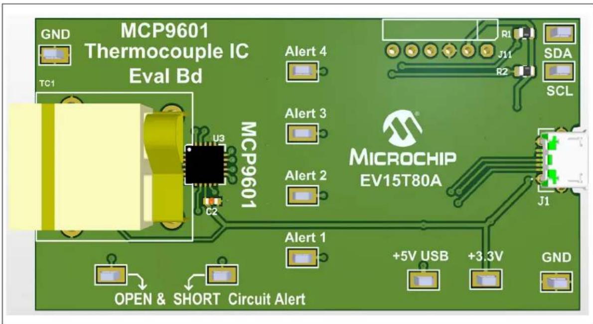
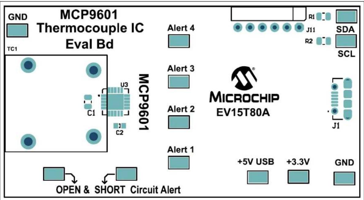
- The MCP9601 Thermocouple IC Evaluation Board has a mini USB connector. The USB connection is needed for power and data acquisition.
text_image
GND MCP9601 Thermocouple IC Eval Bd TC1 U3 MCP9601 Alert 4 Alert 3 Alert 2 MicroCHIP EV15T80A C2 J1 R1 J11 R2 SDA SCL J1 +5V USB +3.3V GND OPEN & SHORT Circuit AlertFIGURE 2-1: MCP9601 Thermocouple IC Evaluation Board.
2.3.2 Hardware Operation
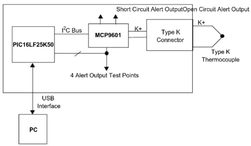
The MCP9601 Thermocouple IC Evaluation Board is fully powered from a PC USB 5V source. Once power is applied and the USB is successfully enumerated, the PIC ^® microcontroller is ready to receive commands from GUI MCP9601 settings or transfer temperature data.
flowchart
graph TD
    A["PC"] -->|USB Interface| B["PIC16LF25K50"]
    B -->|I²C Bus| C["MCP9601"]
    C -->|K+| D["Type K Connector"]
    D -->|K+| E["Short Circuit Alert Output Open Circuit Alert Output"]
    C -->|4 Alert Output Test Points| F["User Interface"]
    C --> G["User Interface"]
FIGURE 2-2: Functional Block Diagram.
The block diagram (Figure 2-2) shows that the thermocouple connector is directly connected to the MCP9601. The four Alert outputs are connected to test points for external connections. Additionally, these outputs are also connected to the microcontroller I/O pins so that the Alert Output statuses can be detected in software.
2.4 MICROCHIP THERMAL MANAGEMENT SOFTWARE GUI
The Microchip Thermal Management Graphical User Interface allows users to evaluate the MCP9601 for temperature-sensing applications. This software tool can be downloaded and installed from the evaluation board product page. The software requires the 'Microsoft.NET Framework' package. If this framework package is not installed on the computer, then the software will automatically download and install it. After the installation is successfully completed, the hardware is required to start the graphical user interface.
Once the hardware is connected, the software recognizes the device ID and displays the corresponding GUI for the evaluation board. Disconnecting the USB will close the GUI. This tool enables the user to evaluate the sensor features and perform temperature data logging.
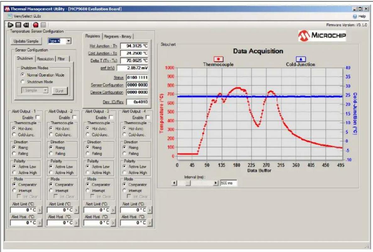
Figure 2-3 shows the data acquisition interface with a plot of the thermocouple Hot-Junction and Cold-Junction temperature data. The Y1 axis is the Hot-Junction temperature and the Y2 axis is the Cold-Junction temperature. This data can also be exported by right-clicking the plot and following the export options.
text_image
Thermal Management Utility - [MCP9600 Evaluation Board] View/Select GUo Temperature Sensor Configuration Update/Sample Type X Sensor Configuration Shutdown Resolution Filter Shutdown Modes Normal Operation Mode Shutdown Mode Sample Burst Registers Registers - Binary Hot Junction - Th 94.3125 °C Cold Junction - Tc 24.2500 °C Delta T (Th - Tc) 70.0625 °C amf (mV) 2.8572 mV Status 0100 1111 Sensor Configuration 0000 0000 Device Configuration 0000 0000 Dev ID/Rev 0x4010 Alert Output - 1 Enable □ Thermocouple Hot-Junc Cold-Junc. Direction Rising Falling Polarity Active Low Active High Mode Comparator Interrupt Int Clear Alert Limit (°C) 0 °C > Alert Hyst. (°C) 0 °C > Alert Output - 2 Enable □ Thermocouple Hot-Junc Cold-Junc. Direction Rising Falling Polarity Active Low Active High Mode Comparator Interrupt Int Clear Alert Limit (°C) 0 °C > Alert Hyst. (°C) 0 °C > Alert Output - 3 Enable □ Thermocouple Hot-Junc Cold-Junc. Direction Rising Falling Polarity Active Low Active High Mode Comparator Interrupt Int Clear Alert Limit (°C) 0 °C > Alert Hyst. (°C) 0 °C > Alert Output - 4 Enable □ Thermocouple Hot-Junc Cold-Junc. Direction Rising Falling Polarity Active Low Active High Mode Comparator Interrupt Int Clear Alert Limit (°C) 0 °C > Alert Hyst. (°C) 0 °C > Alert Output - 5 Thermocouple Hot-Junc Cold-Junc. Direction Rising Falling Polarity Active Low Active High Mode Comparator Interrupt Int Clear Alert Limit (°C) 0 °C > Alert Hyst. (°C) 0 °C > Alert Output - 6 Thermocouple Hot-Junc Cold-Junc. Direction Rising Falling Polarity Active Low Active High Mode Comparator Interrupt Int Clear Alert Limit (°C) 0 °C > Alert Hyst. (°C) 0 °C > Alert Output - 7 Thermocouple Hot-Junc Cold-Junc. Direction Rising Falling Polarity Active Low Active High Mode Comparator Interrupt Int Clear Alert Limit (°C) 0 °C > Alert Hyst. (°C) 0 °C > Alert Output - 8 Thermocouple Hot-Junc Cold-Junc. Direction Rising Falling Polarity Active Low Active High Mode Comparator Interrupt Int Clear Alert Limit (°C) 0 °C > Alert Hyst. (°C) 0 °C > Alert Output - 9 Thermocouple Hot-Junc Cold-Junc. Direction Rising Falling Polarity Active Low Active High Mode Comparator Interrupt Int Clear Alert Limit (°C) 0 °C > Alert Hyst. (°C) 0 °C > Alert Output - 10 Thermocouple Hot-Junc Cold-Junc. Direction Rising Falling Polarity Active Low Active High Mode Comparator Interrupt Int Clear Alert Limit (°C) 0 °C > Alert Hyst. (°C) 0 °C > Alert Output - 11 Thermocouple Hot-Junc Cold-Junc. Direction Rising Falling Polarity Active Low Active HighFIGURE 2-3: Data Acquisition Interface.
MCP9601 Thermocouple IC Evaluation Board User's Guide
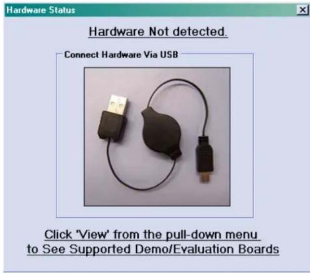
Use the Thermal Management Software Graphical User Interface (GUI) for temperature data logging or to evaluate the sensor board features. If the hardware is properly connected, the software will recognize the hardware, otherwise, the software will show the 'Hardware Not Detected' message box, as indicated in Figure 2-4.
text_image
Hardware Status Hardware Not detected. Connect Hardware Via USB Click 'View' from the pull-down menu to See Supported Demo/Evaluation BoardsFIGURE 2-4: Hardware Not Detected Message Box.
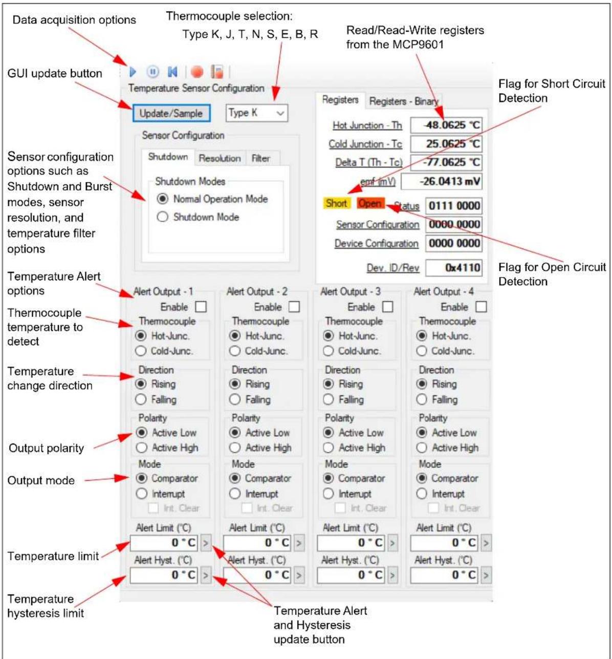
2.5 CONFIGURING THE MCP9601
Figure 2-5 shows the user interface for various sensor options. Once these options are selected, the software programs the device and refreshes the GUI from the device. Therefore the GUI displays the updated device settings.
text_image
Data acquisition options Thermocouple selection: Type K, J, T, N, S, E, B, R Read/Read-Write registers from the MCP9601 GUI update button Temperature Sensor Configuration Update/Sample Type K Sensor Configuration Shutdown Resolution Filter Shutdown Modes ● Normal Operation Mode ○ Shutdown Mode Registers Registers - Binary Hot Junction - Th -48.0625 °C Cold Junction - Tc -25.0625 °C Delta T (Th - Tc) -77.0625 °C emf (mV) -26.0413 mV Short Open Status 0111 0000 Sensor Configuration 0000 0000 Device Configuration 0000 0000 Dev. ID/Rev 0x4110 Flag for Short Circuit Detection Flag for Open Circuit Detection Sensor configuration options such as Shutdown and Burst modes, sensor resolution, and temperature filter options Temperature Alert options Thermocouple temperature to detect Temperature change direction Output polarity Output mode Temperature limit Temperature hysteresis limit Alert Output - 1 Enable □ Thermocouple ● Hot-Junc. ○ Cold-Junc. Direction ● Rising ○ Falling Polarity ● Active Low ○ Active High Mode ● Comparator ○ Interrupt □ Int. Clear Alert Output - 2 Enable □ Thermocouple ● Hot-Junc. ○ Cold-Junc. Direction ● Rising ○ Falling Polarity ● Active Low ○ Active High Mode ● Comparator ○ Interrupt □ Int. Clear Alert Output - 3 Enable □ Thermocouple ● Hot-Junc. ○ Cold-Junc. Direction ● Rising ○ Falling Polarity ● Active Low ○ Active High Mode ● Comparator ○ Interrupt □ Int. Clear Alert Output - 4 Enable □ Thermocouple ● Hot-Junc. ○ Cold-Junc. Direction ● Rising ○ Falling Polarity ● Active Low ○ Active High Mode ● Comparator ○ Interrupt □ Int. Clear Alert Limit (°C) 0 °C > 0 °C > 0 °C > 0 °C > 0 °C > 0 °C > 0 °C > 0 °C > 0 °C > 0 °C > 0 °C > 0 °C > 0 °C > 0 °C > 0 °C > 0 °C > 0 °C > 0 °C > 0 °C > 0 °C > 0 °C > Temperature Alert and Hysteresis update buttonFIGURE 2-5: Sensor Configuration Options.
2.5.1 MCP9600 vs. MCP9601 Additional Features
The MCP9601 family integrates an open circuit and short circuit detection mechanism. When open/short circuit is detected, the device asserts an Alert signal using the SC Alert and OC Alert pins. There are test points for these pins on the MCP9601 evaluation board, which can be used to detect open circuit and short circuit conditions.
Additionally, the status register bits 4 and 5 are also set when the open circuit and short circuit conditions are true. However, the MCP9600 family supports only open circuit detection which can only be read by the host controller from the status register. The MCP9600 does not integrate the alert output pin for open circuit detection.
2.5.2 How to Check for Open Circuit and Short Circuit Conditions
The GUI shows the open circuit and short circuit flags using a yellow and red colored texts as shown in Figure 2-5. These features can be validated by simply disconnecting the thermocouple header from the board for open circuit detection, or by shorting the thermocouple wire to the system ground or power source ( V_SS or V_DD test points on the evaluation board).
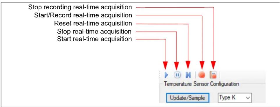
The black "Play", "Stop", and "Reset" icons (Figure 2-6) can be used to perform continuous data acquisitions. The red "Record" icon enables the user to data log to an external file. The logging interval can be adjusted using the Interval scroll bar from 100 ms to 30s, as shown in Figure 2-3.
flowchart
graph TD
    A["Stop recording real-time acquisition"] --> B["Start/Record real-time acquisition"]
    B --> C["Reset real-time acquisition"]
    C --> D["Stop real-time acquisition"]
    D --> E["Start real-time acquisition"]
    E --> F["Temperature Sensor Configuration"]
    F --> G["Update/Sample"]
    F --> H["Type K"]
FIGURE 2-6: Real-Time Acquisition.
The data acquisition display chart (Figure 2-3) can be customized. The customizing options (Figure 2-7) can be selected by either double-clicking or right-clicking the chart (Figure 2-3). The displayed data can also be exported.

text_image
Data Acquisition Customization... General Plot Subsets Points Axis Font Color Style Main Title: Data Acquisition Sub Title: Show Annotations Border Style ○ No Border ○ Line ● Shadow ○ 3D Inset Numeric Precision ○ 0 ○ 1 ○ 2 ○ 3 Viewing Style ● Color ○ Monochrome ○ Monochrome + Symbols Grid Lines ● Both ○ Y ○ X ○ None ✓ Grid in front of data Display ● Graph ○ Table ○ Both Font Size ● Large ○ Medium ○ Small OK Cancel Apply Help Export... Maximize... Export DataFIGURE 2-7: Chart Setup Options.
MCP9601 Thermocouple IC Evaluation Board User's Guide
NOTES:
Appendix A. Schematic and Layouts
A.1 INTRODUCTION
This appendix contains the following schematics and layouts for the MCP9601 Thermocouple IC Evaluation Board:
- Schematic 1
- Schematic 2
- Board – Top Silk
- Board – Top Copper and Silk
- Board – Top Copper
- Board – Bottom Copper
- Board – Bottom Copper and Silk
- Board – Bottom Silk
A.2 SCHEMATIC 1

text_image
Connectivity U2 13 12 11 10 9 8 7 6 5 4 3 2 1 0 -3.3V LSR P LSR N VUSBIV3 VDD VSS VSS FP RAC1/2IN6-AN0 RA1/C12IN1-AN1 RA2/C2IN8-AN2/DACOU1/VREF- RA3/C1IN-AN3/VREF+ RA4/C1OUT/SRQ/TCKI RA5/C2OUT/SRNO/SSHLVDIN/AN4 RA6/CLKOOSC2 RA7/C1 KIOSC1 RB0/AN12/SRFFLT8/SDI/SDA/INT0 RB1/AN10/C12IN3-PIC/SCK/SCT/INT1 RB2/AN8/CTEDLP1B/INT2 RB3/AN9/C12IN3-CTED2/CCP2/SDO RB4/AN12/PID/OCB4 RB5/AN13/TIG/TCK/HOCB5 RB6/IOCB6/PGC RB7/IOCB7/PGD MCTEAPP/RT3 27 28 29 30 31 32 33 34 35 36 37 38 39 40 41 42 43 44 45 46 47 48 49 50 51 52 53 54 55 56 57 58 59 60 61 62 63 64 65 66 67 68 69 70 71 72 73 74 75 76 77 78 79 80 81 82 83 84 85 86 87 88 89 90 91 92 93 94 95 96 97 98 99 100 101 102 103 104 105 106 107 108 109 110 111 C3 0.1uF 10V 0603 GND GND C1B 0.1uF 10V 0603 GND HCR 2.54 MALE 1x6 J11 DNP MCLR -3.3V PDND PDC PCCA.3 SCHEMATIC 2

text_image
THERMOCOUPLES 70V GND FB2 Tetrae Base1 FB3 Tetrae Base2 FB4 2.4V GN1 R3 2.4V R4 2V 13.5V Vin+ -1.1V 175.2V C1 2.1A 10V 208 Vcc+ -1.1V 175.2V Bottom Side Blue Bottom Side Red GND R6 100V GN1 GND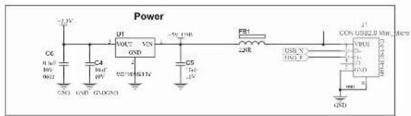
text_image
Power U1 VOUT VIN GND C4 GND GND C5 GND F21 220R USB X INCL F USB US$2.0 Min GND CON US$2.0 Min GND
text_image
3.2V -1.3V S1 4.9V 6.0V 1K R2 2.5V 6.0V 1P C2 SND GND GND GND MCPs Aout 4 Aout 5 Aout 6 Aout 7 Aout 8 Aout 9 Aout 10 Aout 11 Aout 12 Aout 13 Aout 14 Aout 15 Aout 16 Aout 17 Aout 18 Aout 19 Aout 20 Aout 21 Aout 22 Aout 23 Aout 24 Aout 25 Aout 26 Aout 27 Aout 28 Aout 29 Aout 30 30 VOUT SOUT 1.3V 0.2V 10V 10V Input SOUT GND OPEN CIRCUIT ALERT OUT ALAP OUT ALAP SHORT CIRCUIT ALERT
text_image
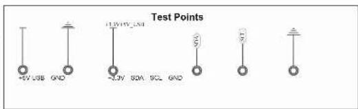
Test Points +5V USB GND +1.2V/10V_2.5V -3.2V 80A 9CL GNDMCP9601 Thermocouple IC Evaluation Board User's Guide
A.4 BOARD - TOP SILK
text_image
MCP9601 Thermocouple IC Eval Bd GND TC1 Alert 4 R1 SDA R2 SCL MCP9601 U3 C1 C2 Alert 3 Alert 2 Alert 1 MICROCHIP EV15T80A J1 OPEN & SHORT Circuit Alert +5V USB +3.3V GNDA.5 BOARD – TOP COPPER AND SILK

text_image
MCP9601 Thermocouple IC Eval Bd GND TC1 U3 C1 L C2 Alert 4 Alert 3 Alert 2 Alert 1 MicroCHIP EV15T80A R1 J11 R2 SDA SCL J1 +5V USB +3.3V GND OPEN & SHORT Circuit AlertA.6 BOARD -TOP COPPER
natural_image
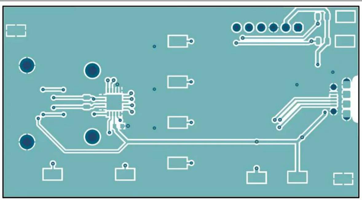
Pure electrical circuit lines without any symbolsA.7 BOARD - BOTTOM COPPER
natural_image
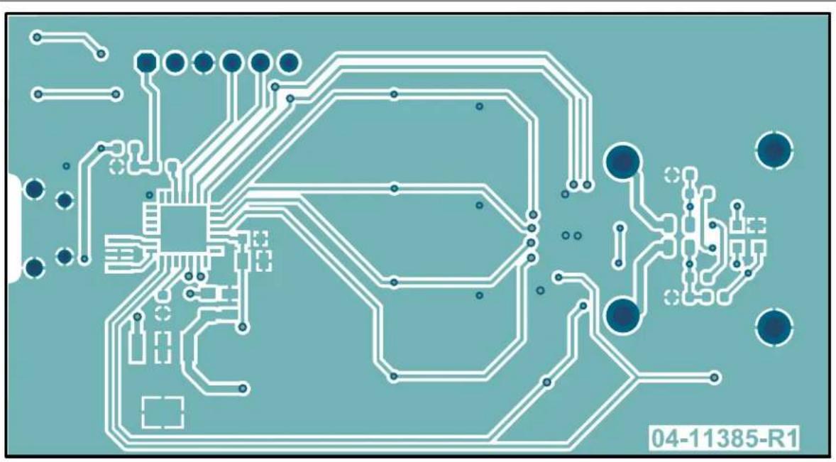
Pure electrical circuit lines without any symbols or text, rendered in blue and white on a teal background (no readable text or labels)A.8 BOARD - BOTTOM COPPER AND SILK

text_image
PAD4 R24 C18 R16 U2 x1 C3 C5 FB1 LABEL1 PAD3 u1 RAD2 RoHS R7 R6 FB3 FB2 D1 R5 R3 R4 PAD1 04-11385-R1A.9 BOARD - BOTTOM SILK

text_image
PAD4 R21 R16 C18 U2 x1 C6 C4 C3 C5 FB1 LABEL1 PAD3 u1 PAD1 50 CE PAD2 RoHS FB3 D1 FB2 R5 R3 R4 PAD1Appendix B. Bill of Materials (BOM)
TABLE B-1: BILL OF MATERIALS (BOM)
| Qty. | Reference Description | Manufacturer Part Number | ||
| 12 +3 | .3V, +5V USB, Alert 1, Alert 2, Alert 3, Alert 4, GND, SCL, SDA, TP1, TP2 | Connector, TP, loop, silver, 0.38, SMD | Keystone ^ Electronics Corp. | 5018 |
| 5 C1 | C2, C3, C6, C18 | Capacitor, ceramic, 0.1 μF, 10V, 10%, X7R, SMD, 0603 | KEMET C0603C104K8R | ACTU |
| 2 | C4, C5 | Capacitor, ceramic, 10 μF, 10V, 10%, X5R, SMD, 0805 | Taiyo Yuden Co., Ltd. | LMK212BJ106KD-T |
| 1 | D1 | TVS, diode, 5.5V, SOT143B | Nexperia | PRTR5V0U2X,215 |
| 1 FB1 | Ferrite, 2A, 220R, SMD, 0805 | Murata Electronics ^ | BLM21PG221SN1D | |
| 2 | FB2, FB3 | Ferrite, 800 mA, 0.15R, SMD, 0805 | Laird Technologies ^ | LI0805H151R-10 |
| 1 J1 | Connector, USB, 2.0 MICRO-B, female, TH/SMD, R/A | Amphenol Corporation | 10118194-0001LF | |
| 1 J11 | Connector, header-2.54, male, 1x6, gold, 6.10MH, TH R/A - DO NOT POPULATE | 3M | 961106-5604-AR | |
| 1 LABEL1 | Label, PCBA, 18x6mm, Datamatrix, Assy# / Rev / Serial / Date | Logimark AB | 505462 | |
| 4 PAD1, PAD2, PAD3, PAD4 | Mechanical, hardware, rubber pad, Cylindrical, D7.9, H5.3, black | 3M | SJ61A11 | |
| 1 PCB | MCP9601 Thermocouple IC Evaluation Board - Printed Circuit Board | — | 04-11385-R2 | |
| 2 R1, R2 Resistor, TKF | 4.99k, 1%, 1/10W, SMD, 0603 | Panasonic ^ - ECG | ERJ-3EKF4991V | |
| 1 R3 | Resistor, SMD, 2.49M, Ohm, 1%, 1/10W, 0603 | Yageo Corporation | RC0603FR-072M49L | |
| 1 R4 | Resistor, TKF, 2M, 5%, 1/10W, SMD, 0603 | Panasonic - ECG | ERJ-3GEYJ205V | |
| 3 R5, R6, R16 | Resistor, TKF, 100R, 5%, 1/10W, SMD, 0603 | Vishay/Dale | CRCW0603100RJNEA | |
| 1 R7 | Resistor, SMD, 487K, Ohm, 1%, 1/10W, 0603 | Panasonic - ECG | ERJ-3EKF4873V | |
| 1 R21 | Resistor, TF, 10k, 1%, 1/16W, SMD, 0603 | TE Connectivity, Ltd. | CPF0603F10KC1 | |
| 1 TC1 | Mechanical, hardware, adapter, Thermocoupler, TH, R/A | Omega ^ Engineering Inc. | PCC-SMP-K-100 | |
| 1 U1 | Microchip, Analog, LDO, 3.3V, MCP1825ST-3302E/DB, SOT-223-3 | Microchip Technology Inc. | MCP1825ST-3302E/DB | |
| 1 U2 | Microchip, MCU 8 | Bit, 48 MHz32 kB, 2kB, PIC18LF25K50-I/ML,QFN-28 | MicrochipTechnology Inc. | PIC18LF25K50-I/ML |
| 1 U3 | MCP9601 Thermocouple EMF toTemperature Converter | MicrochipTechnology Inc. | MCP9601-I/MXMQFN-20 | |
| 1 X1 | Resonator, 20 MHz, 0.1%, SMDCSTCE-V13L – DO NOTPOPULATE | Murata Electronics CSTCE20M0V13L99-R0 | ||
Note: The components listed in this Bill of Materials are representative of the PCB assembly. The released BOM used in manufacturing uses all RoHS-compliant components.
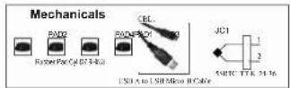
TABLE B-2: BILL OF MATERIALS – MECHANICAL PARTS
| Qty. | Reference Description | Manufacturer | Part Number | |
| 1 | CBL1 | Mechanical, hardware, cable, USB, male, A TO USB, Male, Micro-B, 0.91M | Qualtek Electronics Corporation | 3025030-03 |
| 1 | JC1 | Sensor, temperature, 5SRTC-TT-K-24-36, Subminiature Connector | Omega Engineering Inc. | 5SRTC-TT-K-24-36 |
Note: The components listed in this Bill of Materials are representative of the PCB assembly. The released BOM used in manufacturing uses all RoHS-compliant components.
Worldwide Sales and Service
AMERICAS
Corporate Office
2355 West Chandler Blvd.
Chandler, AZ 85224-6199
Tel: 480-792-7200
Fax: 480-792-7277
Technical Support:
http://www.microchip.com/
support
Web Address:
www.microchip.com
Atlanta
Duluth, GA
Tel: 678-957-9614
Fax: 678-957-1455
Austin, TX
Tel: 512-257-3370
Boston
Westborough, MA
Tel: 774-760-0087
Fax: 774-760-0088
Chicago
Itasca, IL
Tel: 630-285-0071
Fax: 630-285-0075
Dallas
Addison, TX
Tel: 972-818-7423
Fax: 972-818-2924
Detroit
Novi, MI
Tel: 248-848-4000
Houston, TX
Tel: 281-894-5983
Indianapolis
Noblesville, IN
Tel: 317-773-8323
Fax: 317-773-5453
Tel: 317-536-2380
Los Angeles
Mission Viejo, CA
Tel: 949-462-9523
Fax: 949-462-9608
Tel: 951-273-7800
Raleigh, NC
Tel: 919-844-7510
New York, NY
Tel: 631-435-6000
San Jose, CA
Tel: 408-735-9110
Tel: 408-436-4270
Canada - Toronto
Tel: 905-695-1980
Fax: 905-695-2078
ASIA/PACIFIC
Australia - Sydney
Tel: 61-2-9868-6733
China - Beijing
Tel: 86-10-8569-7000
China - Chengdu
Tel: 86-28-8665-5511
China - Chongqing
Tel: 86-23-8980-9588
China - Dongguan
Tel: 86-769-8702-9880
China - Guangzhou
Tel: 86-20-8755-8029
China - Hangzhou
Tel: 86-571-8792-8115
China - Hong Kong SAR
Tel: 852-2943-5100
China - Nanjing
Tel: 86-25-8473-2460
China - Qingdao
Tel: 86-532-8502-7355
China - Shanghai
Tel: 86-21-3326-8000
China - Shenyang
Tel: 86-24-2334-2829
China - Shenzhen
Tel: 86-755-8864-2200
China - Suzhou
Tel: 86-186-6233-1526
China - Wuhan
Tel: 86-27-5980-5300
China - Xian
Tel: 86-29-8833-7252
China - Xiamen
Tel: 86-592-2388138
China - Zhuhai
Tel: 86-756-3210040
ASIA/PACIFIC
India - Bangalore
Tel: 91-80-3090-4444
India - New Delhi
Tel: 91-11-4160-8631
India - Pune
Tel: 91-20-4121-0141
Japan - Osaka
Tel: 81-6-6152-7160
Japan - Tokyo
Tel: 81-3-6880-3770
Korea - Daegu
Tel: 82-53-744-4301
Korea - Seoul
Tel: 82-2-554-7200
Malaysia - Kuala Lumpur
Tel: 60-3-7651-7906
Malaysia - Penang
Tel: 60-4-227-8870
Philippines - Manila
Tel: 63-2-634-9065
Singapore
Tel: 65-6334-8870
Taiwan - Hsin Chu
Tel: 886-3-577-8366
Taiwan - Kaohsiung
Tel: 886-7-213-7830
Taiwan - Taipei
Tel: 886-2-2508-8600
Thailand - Bangkok
Tel: 66-2-694-1351
Tel: 43-7242-2244-39
Fax: 43-7242-2244-393
Denmark - Copenhagen
Tel: 45-4485-5910
Fax: 45-4485-2829
Finland - Espoo
Tel: 358-9-4520-820
France - Paris
Tel: 33-1-69-53-63-20
Fax: 33-1-69-30-90-79
Germany - Garching
Tel: 49-8931-9700
Germany - Haan
Tel: 49-2129-3766400
Germany - Heilbronn
Tel: 49-7131-72400
Germany - Karlsruhe
Tel: 49-721-625370
Germany - Munich
Tel: 49-89-627-144-0
Fax: 49-89-627-144-44
Germany - Rosenheim
Tel: 49-8031-354-560
Israel - Ra'anana
Tel: 972-9-744-7705
Italy - Milan
Tel: 39-0331-742611
Fax: 39-0331-466781
Italy - Padova
Tel: 39-049-7625286
Netherlands - Drunen
Tel: 31-416-690399
Fax: 31-416-690340
Norway - Trondheim
Tel: 47-7288-4388
Poland - Warsaw
Tel: 48-22-3325737
Romania - Bucharest
Tel: 40-21-407-87-50
Spain - Madrid
Tel: 34-91-708-08-90
Fax: 34-91-708-08-91
Sweden - Gothenberg
Tel: 46-31-704-60-40
Sweden - Stockholm
Tel: 46-8-5090-4654
UK - Wokingham
Tel: 44-118-921-5800
Fax: 44-118-921-5820