Smart-UPS SRT011 - Inverter APC - Free user manual and instructions
Find the device manual for free Smart-UPS SRT011 APC in PDF.

User questions about Smart-UPS SRT011 APC
0 question about this device. Answer the ones you know or ask your own.
Ask a new question about this device
Download the instructions for your Inverter in PDF format for free! Find your manual Smart-UPS SRT011 - APC and take your electronic device back in hand. On this page are published all the documents necessary for the use of your device. Smart-UPS SRT011 by APC.
USER MANUAL Smart-UPS SRT011 APC
Installation Guide Smart-UPS™ On-Line SRT011/SRT012
Important Safety Information
Read the instructions carefully to become familiar with the equipment before trying to install, operate, service or maintain it. The following special messages may appear throughout this manual or on the equipment to warn of potential hazards or to call attention to information that clarifies or simplifies a procedure.
The addition of this symbol to a Danger or Warning safety label indicates that an electrical hazard exists which will result in personal injury if the instructions are not followed.

This is the safety alert symbol. It is used to alert you to potential personal injury hazards. Obey all safety messages that follow this symbol to avoid possible injury or death. Safety and General Information
| CAUTION |
| CAUTION indicates a potentially hazardous situation which, if not avoided, can result in minor or moderate injury. |
| NOTICE |
| NOTICE used to address practices not related to physical injury. The safety alert symbol is not used with this signal word. |
Inspect the package contents upon receipt. Notify the carrier and dealer if there is any damage.
Adhere to all local and national electrical codes.

Recycle the packaging.
Deenergizing safety
The UPS contains internal batteries and may present a shock hazard even when disconnected from the branch circuit (mains). Before installing or servicing the equipment, check that the internal batteries are removed, that external extended run batteries are disconnected and the branch circuit (mains) is disconnected.
Hardwire safety
- Verify that all branch circuit (mains) and low voltage (control) circuits are deenergized, and locked out before installing cables or making connections, whether in the junction box or to the UPS.
- Wiring by a qualified electrician is required.
- Adhere to all national and local codes.
- Select wire size and connectors according to national and local codes.
- Strain relief is required for all hardwiring.
- All openings allowing access to UPS hardwiring terminals must be covered. Failure to do so may result in personal injury or equipment damage.
Package Contents
| SRT011 - APC Smart-UPS SRT3000 VA PDU, 208 V (3) L6 - 30 | ||
PDU 4 Torx screws | 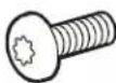 x41 ground screw x41 ground screw | |
| SRT012 - APC Smart-UPS SRT 2200/3000 VA Output HW Kit | ||
| Output module Input module 4 Torx screws | su01109b | x41 ground screw |
x4
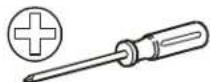
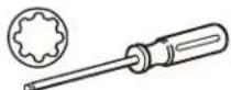
Required tools
| All Models SRT012 | ||||
| Phillips screw driver T20 Torx screw driver Flat head screw driver Wire cutter Wire striper | ||||
 |  |  |  |  |
Disconnect PDU Connectors
 |  |
SRT011
The UPS and PDU models may vary in appearance from those depicted in the diagrams. The PDU installation procedure is similar for SRT011 models.
| PDU UPS Models | |
| SRT011 SRT3000XLT | SRT3000RMXLT |
| SRT3000RMXLT-NC | |
| SRT3000XLW-IEC | |
| SRT3000RMXLW-IEC | |
Remove standard PDU
1

text_image
x5 suc110p2
See "Disconnect PDU Connectors" on page 3.

natural_image
Technical line drawing of a server rack with an inset showing internal components (no text or symbols)Install SRT011
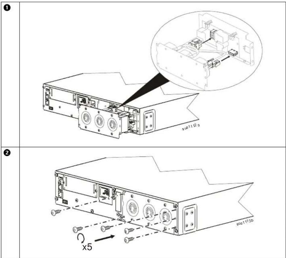
text_image
① su01112a ② x5 su01113bThe SRT011 installation is complete. See "Configure UPS for PDU Panel" on page 10.
SRT012
The UPS and PDU models may vary in appearance from those depicted in the diagrams. The PDU installation procedure is similar for SRT012 models.
Wiring Specifications
 |
| DAMAGE TO EQUIPMENT OR PERSONNELAdhere to all national and local electrical codes.Wiring must be performed by a qualified electrician.Use copper wire for hardwiring.Use snap in strain reliefs.The UPS must be wired into a branch circuit, equipped with a circuit breaker rated as specified in the tables below.Actual wire size must comply with required amp capacity and national and local electrical codes.Recommended input terminal screw torque: 7 lbf-in (0.8 Nm).Recommended output terminal screw torque: 10.6 lbf-in (1.2 Nm).Recommended wire strip length: 7 mm - 8 mmFailure to follow these instructions can result in equipment damage and minor or moderate injury |
Recommended strain relief wire range and thread
| Wire range | Thread | Wire range Thread | |
| 10~14 mm (0.39” - 0.55“) PG | 16 | ||
| Metric M25 |
| SRT2200 and SRT3000 models | ||
| Input connections Wire to L1, L2/N, |  | |
| Output connections Wire to L1, L2/N, | ⊥ | |
| Models | Branch Circuit Overcurrent Rating / Building Circuit Breaker (CB) Current Rating | Wire Size, typical | |
| SRT2200XLA/SRT2200RMXLA/SRT2200RMXLA-NC | 20 A 12 AWG | 2.5 mm^2 | |
| SRT3000XLA/SRT3000RMXLA/SRT3000RMXLA-NC | 30 A 10 AWG 4 mm | ^2 | |
| SRT2200XLI/SRT2200RMXLI/SRT2200RMXLI-NC 16 | A 12 AWG 2.5 mm | ^2 | |
| SRT3000XLI/SRT3000RMXLI/SRT3000RMXLI-NC 20 | A 12 AWG 2.5 mm | ^2 | |
| SRT3000XLT/SRT3000RMXLT/SRT3000RMXLT-NC 20 | A* / 2 pole 12 AWG 2.5 mm | ^2 | |
| SRT3000XLW-IEC/SRT3000RMXLW-IEC | 20 A IEC; 20 A UL* / 2 pole | 12 AWG | 2.5 mm^2 |

RISK OF FIRE, RISK OF DAMAGE TO EQUIPMENT OR PERSONNEL
* Connect the UPS models only to a circuit provided with recommended maximum branch circuit overcurrent protection in accordance with the National Electrical Code, ANSI/NFPA 70 and the Canadian Electrical Code, Part I, C22.1.
Failure to follow these instructions can result in fire, equipment damage and minor or moderate injury.
| PDU UPS Models | |
| SRT012 S | SRT2200XLI, SRT2200RMXLI, SRT2200RMXLI-NC, SRT2200XLA, SRT2200RMXLA,SRT2200RMXLA-NCSRT3000XLT, SRT3000RMXLT, SRT3000RMXLT-NC, SRT3000XLI, SRT3000RMXLI, SRT3000RMXLI-NCSRT3000XLA, SRT3000RMXLA, SRT3000RMXLA-NC SRT3000XLW-IEC, SRT3000RMXLW-IEC |
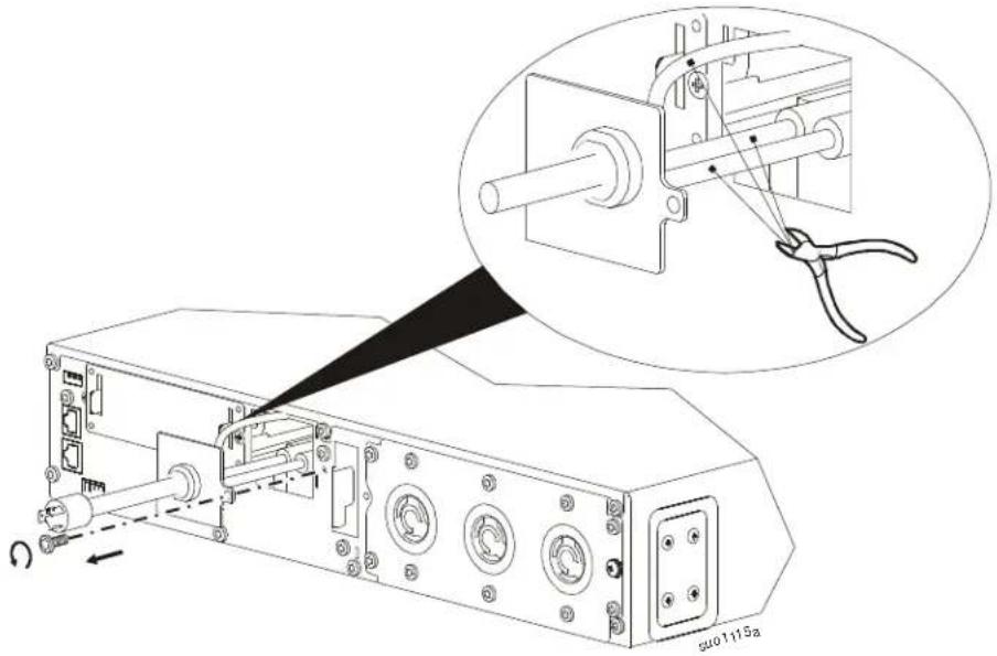
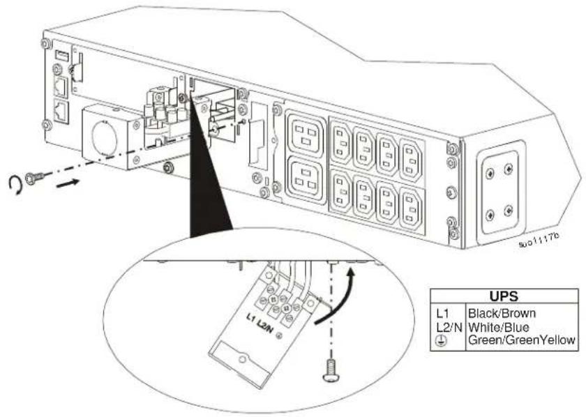
1 Remove the screw securing the input and cut the wires from the input. Note: Cut the wires farthest from the UPS.
XLI, XLW-IEC models

text_image
Technical diagram showing a device with labeled ports and a magnified inset of a mechanical component being adjusted.XLT, XLA models
natural_image
Technical line drawing of an electronic device with a close-up inset showing mechanical components (no text or symbols)2
Connect the UPS wires to the hardwire input box. Secure the hardwire input box to the UPS.
text_image
L1 L2N UPS L1 Black/Brown L2/N White/Blue Green/GreenYellow3
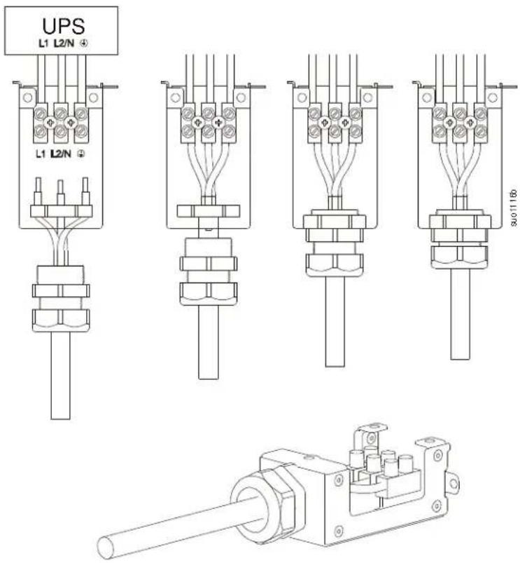
Assemble hardwire input box.
text_image
UPS L1 L2/N + L1 L2/N + 300/116b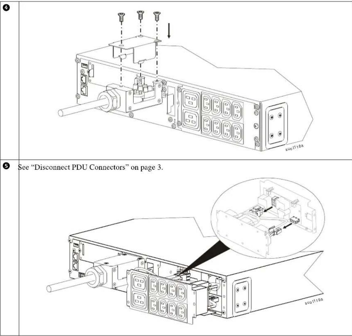
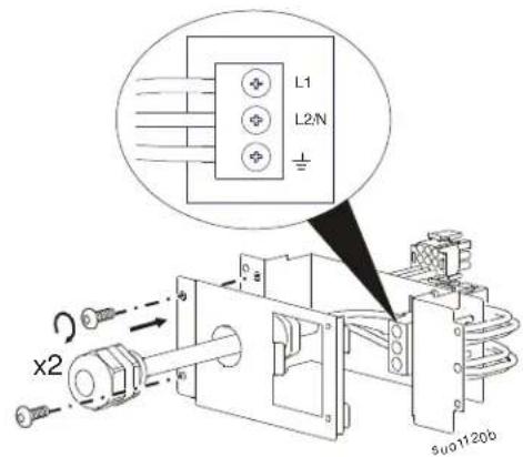
Prepare SRT012
1
text_image
L1 L2/N x2 5u01120b2

text_image
x2 suo1121b1

text_image
Technical diagram of an electronic device with labeled components and a magnified inset showing internal components.Configure UPS for PDU Panel
Reconfigure the UPS, using the display interface, to work with the new PDU.
- Reconnect internal RBC.
- Reconnect the XLBP if installed.
- Reconnect the UPS to utility power. Do not turn on the UPS output.
- Configure the PDU once the display interface message is visible.
- Navigate to the Menu Type. Change the Display Menu Type to Advanced. Main Menu > Configuration > Display > Menu Type > Advanced.
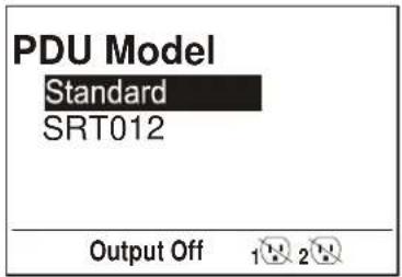
- Navigate to the PDU Model to configure the PDU. Main Menu > Configuration > UPS > PDU Model
- Select the appropriate PDU from the given options and press OK button. Note: The Standard PDU option is the factory default.
PDU options in SRT2200 UPS PDU option in SRT3000 UPS
text_image
PDU Model Standard SRT012 Output Off 1 2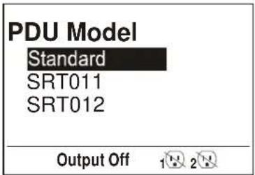
text_image
PDU Model Standard SRT011 SRT012 Output Off 1 2- Wait for 10 seconds for the display interface to reboot.
- Verify that PDU model is updated.
Display Navigation: Main Menu > Configuration > UPS > PDU Model
- Turn on the UPS output.
Customer support and warranty information is available at the APC Web site, www.apc.com.