VO22LHDTV10T - TV VIZIO - Free user manual and instructions
Find the device manual for free VO22LHDTV10T VIZIO in PDF.

User questions about VO22LHDTV10T VIZIO
0 question about this device. Answer the ones you know or ask your own.
Ask a new question about this device
Download the instructions for your TV in PDF format for free! Find your manual VO22LHDTV10T - VIZIO and take your electronic device back in hand. On this page are published all the documents necessary for the use of your device. VO22LHDTV10T by VIZIO.
USER MANUAL VO22LHDTV10T VIZIO
natural_image
Circular orange button with a white V-shaped symbol in the center (no text or numbers)VIZIO
Dear VIZIO Customer,
Congratulations on your new VIZIO VO22L FHDTV10A High Definition LCD Television purchase. Thank you for your support. For maximum benefit of your set, please read these instructions before making any adjustments, and retain them for future reference. We hope you will experience many years of enjoyment from your new VIZIO VO22L FHDTV10A High Definition Television.
For assistance, please call (877)-698-4946 or e-mail us at techsupport@vizio.com.
To purchase or inquire about accessories and installation services for your VIZIO LCD HDTV, please visit our website at www.vizio.com or call toll free at (888)-849-4623.
We recommend you register your VIZIO VO22L FHDTV10A either at our website www.VIZIO.com or fill in your registration card and mail it in. For peace of mind and to protect your investment beyond the standard warranty, VIZIO offers on-site extended warranty service plans. These plans give additional coverage during the standard warranty period. Visit our website or call us to purchase a plan.
Write down the serial number located on the back of your VO22L FHDTV10A.
Purchase Date ____
VIZIO is a registered trademark of VIZIO, Inc. dba V, Inc.
HDMI logo and "High Definition Multimedia Interface" are registered trademarks of HDMI Licensing LLC.
Manufactured under license from Dolby Laboratories.
Dolby and the double-D symbol are trademarks of Dolby Laboratories.

THE TRADEMARKS SHOWN HEREIN ARE THE PROPERTY OF THEIR RESPECTIVE OWNERS; IMAGES USED ARE FOR ILLUSTRATION PURPOSES ONLY. BRAVO, VIZIO AND THE V LOGO AND WHERE VISION MEETS VALUE AND OTHER VIZIO TRADEMARKS ARE THE INTELLECTUAL PROPERTY OF VIZIO INC. PRODUCT SPECIFICATIONS ARE SUBJECT TO CHANGE WITHOUT NOTICE OR OBLIGATION. © 2008 VIZIO INC. ALL RIGHTS RESERVED.
Important Safety Instructions
Your HDTV is designed and manufactured to operate within defined design limits, and misuse may result in electric shock or fire. To prevent your HDTV from being damaged, the following rules should be observed for the installation, use, and maintenance of your HDTV. Read the following safety instructions before operating your HDTV. Keep these instructions in a safe place for future reference.
connecting other components to your HDTV.
HDTV. Do not use a liquid or a spray cleaner for cleaning your HDTV. Do not use abrasive cleaners.
condensation may form in the housing. Wait before turning on your HDTV to avoid causing fire, electric shock, or component damage.
HDTV. When a cart is used, use caution when moving the cart/HDTV combination to avoid injury from tip-over. Do not place your HDTV on an unstable cart, stand, or table. If your HDTV falls, it can injure a person and cause serious damage to your HDTV. Use only a cart or stand recommended by the manufacturer or sold with your HDTV.
as a radiator, heater, oven, amplifier etc. Do not install your HDTV close to smoke. Operating your HDTV close to smoke or moisture may cause fire or electric shock.
reliable operation of your HDTV and to protect it from overheating, be sure these openings are not blocked or covered. Do not place your HDTV in a bookcase or cabinet unless proper ventilation is provided.
objects on the top of your HDTV. Doing so could short circuit parts causing a fire or electric shock. Never spill liquids on your HDTV.
are not sure of the type of power supplied to your home, consult your dealer or local power company.
display. The manufacturer's warranty does not cover user abuse or improper installations.
more information, contact your dealer.
pin). This plug will fit only into a grounded power outlet. This is a safety feature. If your outlet does not accommodate the three-pronged, have an electrician install the correct outlet, or use an adapter to ground your HDTV safely. Do not defeat the safety purpose of the grounded plug.

totally disconnect power, unplug the power cord.

intended to alert the user to the presence of un-isolated, dangerous voltage within the inside of your HDTV that may be of sufficient magnitude to constitute a risk of electric shock to persons.
to alert the user to the presence of important operating and servicing instructions in the literature accompanying your HDTV.


specified voltage may cause fire or electric shock
cord during electrical storms.
This will protect your HDTV from damage due to power surges.
expose you to high voltages, electric shock, and other hazards. If repair is required, contact your dealer and refer all servicing to qualified service personnel.
penetrates into your HDTV, unplug the power cord and contact your dealer. Continuous use in this case may result in fire or electric shock.
the power cord and contact your dealer immediately. Do not try to repair your HDTV yourself.
damaged, the internal components may function abnormally. Unplug the power cord immediately and contact your dealer for repair. Continued use of your HDTV may cause fire or electric shock.
environments with heavy dust or high humidity may cause fire or electric shock.
unplugged before moving your HDTV.
damage the wires inside the cord and cause fire or electric shock. When your HDTV will not be used for an extended period of time, unplug the power cord.
leak which can damage the remote control or injure the operator.
- The power cord fails or frays.
- Liquid sprays or any object drops into your HDTV.
- Your HDTV is exposed to rain or other moisture.
- Your HDTV is dropped or damaged in any way.
- The performance of your HDTV changes substantially.
Television Antenna Connection Protection External Television Antenna Grounding
If an outside antenna/satellite dish or cable system is to be connected to the TV, make sure that the antenna or cable system is electrically grounded to provide some protection against voltage surges and static charges.
Article 810 of the National Electrical Code, ANSI/NFPSA 70, provides information with regard to proper grounding of the mast and supporting structure, grounding of the lead-in wire to an antenna discharge unit, size of the grounding conductors, location of antenna discharge unit, connection to grounding electrodes, and requirements of the grounding electrode.
Lightning Protection
For added protection of the TV during a lightning storm or when it is left unattended or unused for long periods of time, unplug the TV from the wall outlet and disconnect the antenna or cable system.
Power Lines
Do not locate the antenna near overhead light or power circuits, or where it could fall into such power lines or circuits.

text_image
GROUND CLAMP ANTENNA LEAD IN WIRE ANTENNA DISCHARGE UNIT (NEC SECTION 810-20) GROUNDING CONDUCTORS (NEC SECTION 810-21) GROUND CLAMPS ELECTRIC SERVICE EQUIPMENT POWER SERVICE GROUNDING ELECTRODE SYSTEM (NEC ART 250, PART H)Remember, the screen of the coaxial cable is intended to be connected to earth in the building installation.
FCC Bulletin for New TV Owners
After February 17, 2009, a television receiver with only an analog broadcast tuner will require a converter box to receive full power over-the-air broadcasts with an antenna because of the Nation's transition to digital broadcasting. Analog-only TVs should continue to work as before to receive low power, Class A or translator television stations and with cable and satellite TV services, gaming consoles, VCRs, DVD players, and similar products.
Information about the DTV transition is available from http://www.DTV.gov or this manufacturer at 877 MY VIZIO (877-698-4946), and from http://www.dtv2009.gov or 1-888-DTV-2009 for information about subsidized coupons for digital-to-analog converter boxes.
Your HDTV comes with a built-in tuner capable of processing digital broadcasts, making it easier for you to receive this type of signal without the need of an extra converter box.
Opening the Package
Your VIZIO VO22L FHDTV10A and it accompanying accessories are carefully packed in a cardboard carton that has been designed to protect it from transportation damage. Now you have opened the carton check that the VO22L FHDTV10A is in good condition and that all of the accessories are included.
The VO22L FHDTV10A weighs approximately 15lb and is about 21" wide; please exercise care when unpacking the HDTV.
The screen can easily be scratched or broken so please handle the product gently and never place the HDTV with the glass facing downwards on a surface without protective padding.
IMPORTANT: Save the carton and packing material for future shipping.
Package Contents
VIZIO VO22L FHDTV10A
VIZIO Remote Control VR3
VIZIO TV Stand
Power Cord
VIZIO Bezel and Screen Cleaning Cloth
Quick Setup Guide
Registration Card
VIP Services Brochure
2 (Double A) Batteries for the Remote Control
VIZIO Warranty and Repair Information
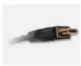
HDMI Cable

natural_image
Black VIZIO monitor with blank screen and stand (no visible text or symbols on body)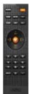


Additional Certified Accessories for your VIZIO TV are sold separately
Wall Mounts
High Definition Cables
Extra or replacement Remote
VIZIO also offers Installation Services and Extended Warranty Services for your VIZIO VO22L FHDTV10A
To purchase or inquire about additional accessories and services for your VIZIO product, visit our web site at www.VIZIO.com or call us toll free at 888-VIZIOCE (888-849-4623)
Installation Preparation
Please read this user manual carefully before installing your VIZIO HDTV.
The power consumption of the TV is up to 80W, please use the power cord designated for TV. When an extension cord is required, use one with the correct power rating. The cord must be grounded and the grounding feature must not be defeated.
The TV should be installed on a flat surface to avoid tipping. For proper ventilation, you must allow space between the back of the TV and the wall. If you would like to mount your TV on the wall, please see below 'Preparing Your LCD HDTV for Wall Mounting' for additional information. Avoid installing the TV in places with high humidity, dust or smoke so as not to shorten the service life of the electronic components. Install the TV in landscape orientation; any 90° clockwise or counter-clockwise installation may induce poor ventilation and excessive component damage.
VIZIO offers professional installation services. Please contact VIZIO for more information on these services at 888-VIZIOCE (888-849-4623) or www.VIZIO.com.
TV Setup and Stand Assembly
Note: We strongly recommend that two people perform the setup and assembly due to the weight and size of the TV.
To unpack the TV and stand base:

natural_image
Open cardboard box containing folded clothes and colorful printed materials (no visible text or symbols)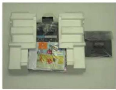
natural_image
White plastic container with packaged goods and a partially visible cover (no text or symbols)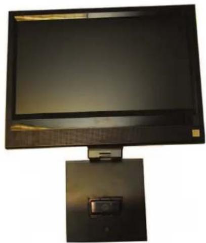
natural_image
Computer monitor with a mounted screen and a small display unit (no visible text or symbols)- Remove the contents from the box.
- Remove the two foam end caps.
- Remove the protective bag from the TV and stand.
- Lay the TV face down on a clean, flat surface.
Note: Make sure that the surface is free of debris to prevent the TV screen from getting scratched.
To attach the TV stand base:
Note: If you will be wall mounting the TV, skip this step and go to the next page for wall mounting instructions.
- Place the base stand upright on a flat surface with the VIZIO logo facing forward.
- Position the TV over the stand with the screen facing forward.
- Press the clip holder on the bottom of the TV into the spring loaded clip in the stand base until you hear it click into place.
- Move the TV into an upright position.

natural_image
Two hands holding a black monitor on a white desk, with a red cloth nearby (no visible text or symbols)
natural_image
Black CRT monitor with a white base, placed on a white surface against a perforated wall (no visible text or symbols)Preparing Your LCD HDTV for Wall Mounting
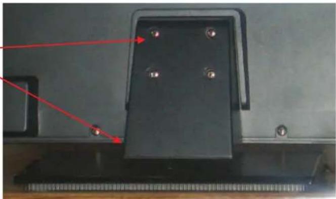
To remove the stand base
- Unplug all of the cables and cords from your VO22L FHDTV10A.
- Place the VO22L FHDTV10A face down on a soft and flat surface (blanket, foam, cloth, etc) to prevent any damage to the TV.
- Push up the plastic panel on the back of the stand and lift it away to release.
text_image
VIZIO TEL: 00000-
Remove the four (4) screws holding the base.
-
Carefully remove the stand base.
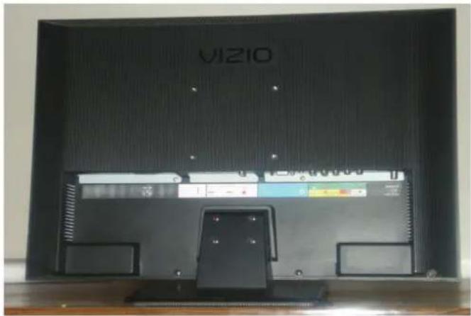
Now, the VO22L FHDTV10A can fit securely to a mount (sold separately) by utilizing the mounting holes in the center of the back panel of the TV. Please make sure to read the instructions of your specific mount to properly hang the VO22L FHDTV10A.
The pitch of the mounting holes is 100mm horizontally and 100mm vertically. The screw type required is metric M4, 1.25mm pitch. The length of the screws will depend on the thickness plate being attached to TV set, our brackets come with different length screws.
natural_image
Close-up of a black electronic device with four pins and red arrows pointing to features (no visible text or symbols)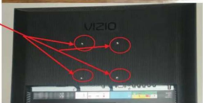
text_image
VIZIOTo find the perfect mount for the VIZIO VO22L FHDTV10A, browse VIZIO's certified mount selection at www.VIZIO.com or call directly 888-VIZIOCE (888-849-4623).
Disassembling Your LCD HDTV
If you want to transport your VO22L FHDTV, it is recommended that you disassemble the TV from the base stand and put the contents back into the original box. Please follow the instructions below to disassemble your VO22L FHDTV.
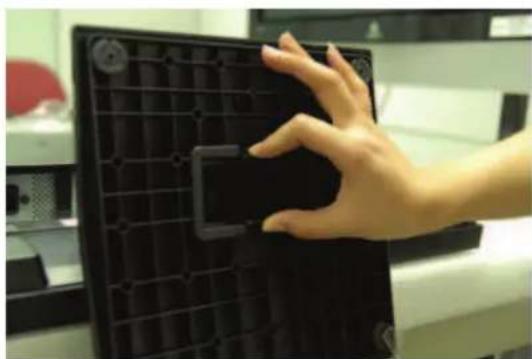
- Familiarize with the base design as show below. These are two points where squeezing pressure must be applied.

natural_image
Top-down view of a black plastic grid plate with red arrows pointing to internal features (no text or symbols visible)- Place the TV face down on a soft (blanket, foam, cloth, etc.) flat surface to prevent any damage to the unit, making sure that the screen is resting well on the surface so that there is not an uneven pressure. Let the base hangs at the edge of the flat surface, as shown below; to make it easier to detach it from the TV.
natural_image
Hand placing a black plastic component into a black tray (no visible text or symbols)- Applying enough squeezing pressure at these two points will release the clips from the locking position, making it smoother to separate the base from the TV.
Note:
If the goal is to remove the Base Stand for wall mounting, please follow the instructions or steps under such topic in the User's Manual.
Table of Contents
Chapter 1 Basic Controls and Connections ...... 12
1.1 Front Panel....12
1.2 Side Panel Controls....12
1.3 Rear Panel Connections 13
1.4 Right-Side Panel Connection 14
1.5 VIZIO Remote Control....15
1.5.1 Insertion of Batteries in the Remote Control 16
1.5.2 Remote Control Range 16
1.5.3 VIZIO Universal Remote Control Precautions 16
Chapter a Connecting Equipment 17
2.1 Which Video Connection Should I Use?......17
2.2 Connecting Coaxial (RF)....18
2.2.1 Using Your Antenna or Digital Cable for DTV....18
2.2.2 Using the Antenna or Cable through your VCR 18
2.3 Connecting Your HDTV Set-Top Box....19
2.3.1 Using HDMI Input 19
2.3.2 Using Component Video....21
2.4 Connecting Your Basic Set-Top Box 22
2.4.1 Using Composite Video 22
2.4.2 Using Coax (RF) 22
2.5 Connecting Your DVD Player....23
2.5.1 Using HDMI Input 23
2.5.2 Using Component Video....25
2.5.3 Using S-Video (AV/S-VIDEO) 26
2.5.4 Using Composite (AV) Video Input 26
2.6 Connecting Your VCR or Video Camera....27
2.7 Connecting an external Receiver/Amp 28
2.7.1 Optical Output of Audio received 28
2.8 Connecting a PC Computer 29
2.8.1 Preset PC Resolutions....30
2.8.2 Resolutions Through RGB Input 30
Setting Up to Watch Television....31
2.9 Basic LCD HDTV Start Up 31
2.10 Watching a TV Program 36
2.11 Adjusting Basic HDTV Settings 37
2.12 Program Information....38
2.13 Information on HDTV Status 38
Chapter 3 Advanced Adjustment of HDTV ....30
3.1 Using the On Screen Display (OSD) 39
3.2 DTV / TV Input Picture Adjustment....40
3.2.1 Backlight 41
3.2.2 Brightness....41
3.2.3 Contrast 42
3.2.4 Color 42
3.2.5 Tint 42
3.2.6 Sharpness 43
3.2.7 Color Temperature....43
3.2.8 Advanced Video 44
3.3 DTV / TV Input Audio Adjustment....46
3.3.1 Volume 46
3.3.2 Bass....46
3.3.3 Treble 47
3.3.4 Balance....47
3.3.5 Surround 47
3.3.6 Digital Audio Out....47
3.3.7 Speakers 48
3.3.8 Lip Sync 48
3.4 DTV / TV Tuner Setup....49
3.4.1 Tuner Mode 49
3.4.2 Auto Search....49
3.4.3 Skip Channel 49
3.4.4 MTS....50
3.4.5 Time Zone 50
3.4.6 Daylight Saving....50
3.5 DTV / TV Input Setup 51
3.5.1 Language....51
3.5.2 Sleep Timer 51
3.5.3 Wide 51
3.5.4 Input Naming 52
3.5.5 Analog Closed Caption 53
3.5.6 Digital Closed Caption 53
3.5.7 Reset All Settings 53
3.6 DTV / TV Input Parental Control....54
3.6.1 Channel Block 54
3.6.2 TV Rating....55
3.6.3 Movie Rating....56
3.6.4 Check for New DTV Rating....56
3.6.5 Blocked Unrated Programming....57
3.6.6 Change the Password ....57
3.7 HDMI Input Picture Adjustment 58
3.8 HDMI Input Audio Adjustment 58
3.9 HDMI Input Setup....58
3.10 Video Input Picture Adjustment 59
3.11 Video Input Audio Adjustment 59
3.12 Video Input Setup....59
3.13 Video Input Parental Control 60
3.14 PC Input Picture Adjustment 60
3.14.1 Auto Adjust 60
3.14.2 Backlight....60
3.14.3 Brightness....61
3.14.4 Contrast....61
3.14.5 Color Temperature....61
3.14.6 H-SIZE 62
3.14.7 H. Position 62
3.14.8 V. Position 62
3.14.9 Fine Tune 63
3.15 PC Input Audio Adjustment 63
3.16 PC Input Setup 63
3.17 Understanding Viewing Features 64
3.17.1 Viewing Modes 64
Chapter 4 Maintenance and Troubleshooting ......65
4.1 Maintenance....65
4.2 Troubleshooting Guide 65
4.3 Telephone & Technical Support 67
4.4 Compliance 68
4.5 FCC Class B Radio Interference Statement....68
Chapter 5 Miscellaneous Information......69
5.1 Specifications 69
5.2 Glossary – Standard Definitions....70
Index 71
Chapter 1 Basic Controls and Connections
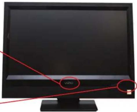
1.1 Front Panel
Power 'VIZIO' light – The VIZIO name lights white when powered on and orange when powered off.
Remote Control Sensor – This is the window through which all of the remote control signals pass to the sensor. Point the remote control directly at this window for the best response to the remote signal.
text_image
v2001.2 Side Panel Controls
POWER ( ) Switch the VO22L FHDTV10A on by pressing the button once. Press the button again to turn the VO22L FHDTV10A off.
MENU – This button activates the On Screen Display (OSD). If a sub-menu is active, pressing this button will return to the previous menu level.
CH + / - - Use these buttons to step up or down the TV channels. While the OSD is active, these buttons function as up and down controls in the OSD menus.
VOL + / -- Use these buttons to increase or decrease to the speaker volume. While the OSD is active, these buttons function as left and right controls in the OSD menus.
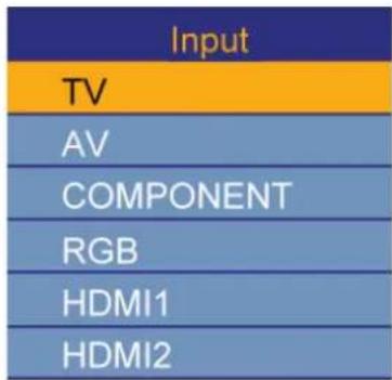
INPUT (ENTER) – Repeated pressing of this buttons steps through the input sources in the following sequence: TV, AV/S-Video, Component, RGB, and HDMI. Once you have stepped through the entire sequence, you will return
text_image
Input TV AV COMPONENT RGB HDMI1 HDMI2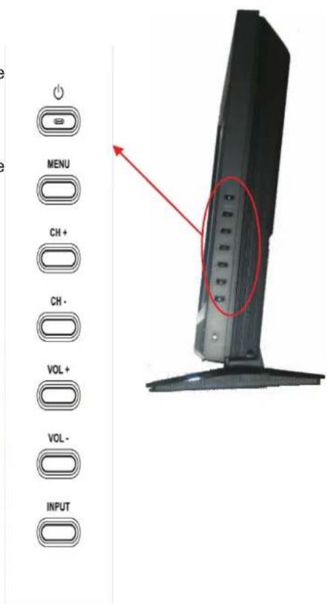
text_image
MENU CH + CH - VOL + VOL - INPUTAdditionally, when the OSD is active, this button confirms the menu function to be adjusted. When the OSD is not active, pressing this button will display the current input mode.
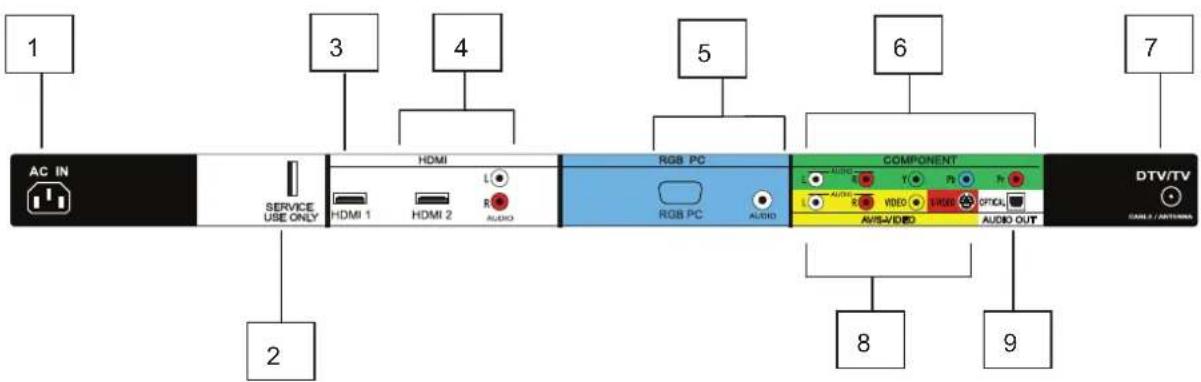
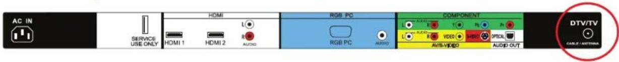
1.3 Rear Panel Connections
text_image
1 3 4 5 6 7 AC IN SERVICE USE ONLY HDMI HDMI 1 HDMI 2 L AUDIO RGB PC RGB PC AUDIO COMPONENT L AUDIO T1 Video MUSIC OPTICAL AVISA/VIDEO AUDIO OUT 8 9-
AC IN – Plug-in the supplied AC Power Cord here.
-
SERVICE – This custom communication port is for factory service only. Use of this input for any purpose other than factory authorized service will void the manufacturer's warranty of this equipment.
-
HDMI 1 – Connect the primary source for digital video such as a DVD multimedia player or set top box through this all digital connector. The white color band on the rear of the TV indicates this connection.
-
HDMI 2 – Connect a third source for digital video such as a DVD multimedia player or set top box through this all digital connector. The white color band on the rear of the TV indicates this connection. For users who want to connect to a DVI enabled device, use a DVI-HDMI cable and connect the Analog Audio output of the device to the L+R AUDIO here. . Your VIZIO Certified HDMI and HDMI-DVI cables are available for purchase from www.VIZIO.com or by calling 888-VIZIOCE (888-849-4623).
-
RGB PC – Connect the video and audio from a computer here. The blue color band on the rear of the TV indicates this connection. A 1/8" plug stereo cable is needed to connect the audio out from the computer to the 1/8" jack connector in the rear of the TV for audio from computer.
-
COMPONENT (YPb/CbPr/Cr with Audio L/R) – Connect the source for component video devices such as a DVD Player or set top box here. From left to right, use green for Y, blue for Pb (or Cb), red for Pr (or Cr), white for left audio and red for right audio inputs. The green color band on the rear of the TV indicates this connection.
-
DTV – Connect to an antenna or digital cable (out-of-the-wall, not from Cable Box) for Digital TV.*
-
AV/S-VIDEO IN – Connect the primary source for composite video devices, such as a VCR or video game. Use the white and red connectors to connect the external audio from the same source, then use the S-Video or yellow connector to connect the external video from the same source. The S-Video, if connected, will take priority over AV RCA (yellow) connector. The yellow color band on the rear of the TV indicates this connection.
-
OPTICAL DIGITAL AUDIO OUT – When a digital audio signal is associated with an input which is selected for viewing, the digital audio associated with digital programming will be available on this SPDIF Optical connector for connection to your home theatre system. The white color band on the rear of the TV indicates this connection.
* For digital TV stations in your area visit www.antennaweb.org.
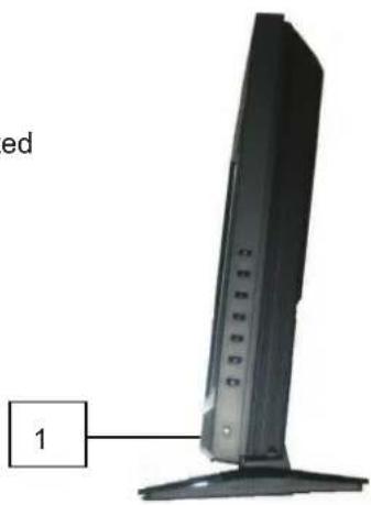
1.4 Right-Side Panel Connection
- HEADPHONE – Connect your headphone here for personalized listening without disturbing others.
text_image
ed 11.5 VIZIO Remote Control
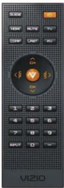
GUIDE – This button displays program information. Press this button once when in TV mode and the information of the program being viewed is shown. Press it a second time and the Electronic Programming Guide will appear in the screen. In any other mode when this button is pressed, the screen will display the selected input plus the definition of the signal; i.e. HDMI 720p, HDMI 1080i, etc.
POWER – Press this button to turn the TV on from the Standby mode. Press it again to return to the Standby mode.
HDMI – Press this button to select the HDMI input.
MUTE – This button turns the sound on and off.
TV – Press this button to select TV.
COMPONENT – Press this button to select the Component (YPbPr) input.
LAST – This button recalls the previously viewed channel. If the On-Screen Display (OSD) menu is being used, this button will allow you to get back to previous menu screen or out to your program when you press it repeatedly.
AV – Press this button to select AV (either Composite or S-Video) input.

(MENU) – Use this button for the On-Screen Display (OSD) menu.
When it is used within a menu selection, the ball key will help you to make the selection of the feature to be adjusted after it has been highlighted.

-These labeled buttons are used to navigate the OSD menu. When

navigating the OSD menu, the arrows control the direction up and

down or left and right. They will also be used as value settings when the slide bar is shown on the screen and option settings to turn feature off or on. During regular TV watching these keys will provide us with the control functions of Volume (up or down) and Channe
(up or down). Channel up or down will not function when a cable box or satellite receiver is being used as the source of the signal.
NUMBER BUTTON PAD – Use these buttons to select a channel or enter a password.
INPUT - This button allows the user to cycle through the inputs. Repeatedly pressing of this button will step you through the input sources in the following sequence: TV, AV/S-VIDEO,
Component1, Component2, RGB, HDMI1, HDMI2, and HDMI3. Once you have stepped through the entire sequence, you will return to the beginning.
- (DASH) - When selecting a digital channel directly use this button for the separation of main and sub-channels. For example, channel 28-2 would be selected by the button sequence 2 8 ENTER 2.
| Input |
| TV |
| AV |
| COMPONENT |
| RGB |
| HDMI1 |
| HDMI2 |

text_image
GUIDE HOME MUTE TV COMP LAST RV CH V OK 1 2 3 4 5 6 7 8 9 INPUT 0 -1.5.1 Insertion of Batteries in the Remote Control
Insert two AA batteries into the remote control. Make sure that you match the (+) and (-) symbols on the batteries with the (+) and (-) symbols inside the battery compartment. Re-attach the battery cover.
Precautionary Tips for Inserting the Batteries:
Only use the specified AA batteries.
Do not mix new and old batteries. This may result in cracking or leakage that may pose a fire risk or lead to personal injury.
Inserting the batteries incorrectly may also result in cracking or leakage that may pose a fire risk or lead to personal injury.
Dispose of the batteries in accordance with local laws and regulations.
Keep the batteries away from children and pets.

natural_image
Close-up of three black cylindrical batteries with visible internal components and a small circular component (no text or symbols)1.5.2 Remote Control Range
Point the remote control at the remote control sensor to transmit the commands.
Do not place any obstacles between the remote control and the receiver window.
The effective range of the remote control is approximately 30 feet (10 meters) from the front of the receiver window, 30^ to the left and right, 20^ up and down.
1.5.3 VIZIO Universal Remote Control Precautions
The remote control should be kept dry and away from heat sources. Avoid humidity.
If the TV responds erratically to the remote control or does not respond at all, check the batteries. If the batteries are low or exhausted, replace them with fresh batteries.
When not using the remote control for a long period of time, remove the batteries.
Do not take the batteries apart, heat them, or throw them into a fire.
Do not subject the remote control to undue physical stress, such as striking or dropping it.
Do not attempt to clean the remote control with a volatile solvent. Wipe it with a clean, damp cloth.
Chapter 2 Connecting Equipment
2.1 Which Video Connection Should I Use?
The VIZIO VO22L FHDTV10A has six different ways to connect your video equipment from a basic connection to the most advanced for digital displays.
| Connection Quality (type) | Connector | Rear Panel Color Codes | Description |
| Best (digital) |  | White | HDMI (High-Definition Multimedia Interface) - It is the first and only industry-supported, uncompressed, all-digital audio/video interface. HDMI provides an interface between any audio/video source, such as a set-top box, DVD player, or A/V receiver and an audio and/or video monitor, such as a digital television (DTV), over a single cable. |
| Best (digital) |  | Black | DTV Coaxial RF. When used for MPEG2 encoded bit streams from ATSC broadcast programming, this input takes advantage of the High Definition content. TV Coaxial RF. This is the connection for standard NTSC TV using antenna or cable. |
| Good (analog) | |||
| Best (analog) | 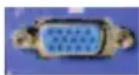 | Blue | RGB PC (VGA) – This video input has separate red, green and blue color components. The signal carries horizontal and vertical sync information on the green signal. This is most commonly used for PC input. |
| Better (analog) | 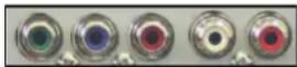 | Green | Component - The video signal is separated into three signals, one containing the black-and-white information and the other two containing the color information. This enhancement over S-Video takes advantage of the superior picture provided by progressive scan DVD players and HDTV formats. |
| Good (analog) |  | Yellow and Red | S-Video (AV) - The video signal is separated into two signals, one containing the black-and-white information and the other containing the color information. Separating the color in this way avoids 'cross color' effects where closely spaced black and white lines are erroneously displayed in color. It also enables text to be displayed more sharply. Composite (AV) - The complete video signal is carried through this single pin connector. This is the most commonly used video connection. |
Note: For more info refer to the Quick Start Guide
2.2 Connecting Coaxial (RF)
2.2.1 Using Your Antenna or Digital Cable for DTV
text_image
AC IN SERVICE USE ONLY HDMI L RGB PC RGB PC AUDIO COMPONENT AUDIO VIDEO AUDIO AUDIO OUT DTV/TV CABLE / ANTICINA- Turn off the power to the HDTV.
- Connect the coaxial (RF) connector from your antenna or digital cable (out-of-the-wall, not from the Cable Box) to the DTV/TV CABLE/ANTENNA connector on the rear of the HDTV.
- Turn on the power to the HDTV.
- Select DTV using the INPUT button on the remote or side of the HDTV, or directly by pressing the TV button on the Remote Control.
Note:
a) Not all digital TV broadcasts are High Definition (HD). Refer to the program guides, or consult your cable, satellite or TV station operator.
b) Digital broadcasts are not available in all areas. Refer to www.antennaweb.org for detailed information.
c) Make sure the antenna and coaxial cable are correctly grounded.
d) For Professional antenna installation contact us at call 1-888-VIZIOCE (1-888-849-4623). www.VIZIO.com or
2.2.2 Using the Antenna or Cable through your VCR

text_image
AC IN SERVICE USE ONLY HDMI HDMI 1 HDMI 2 L AUDIO RGB PC RGB PC AUDIO COMPONENT AUDIO VIDEO AVS-VIDEO AUDIO OUT DTV/TV CABLE / ANTENIX- Turn off the power to the HDTV and VCR.
- Connect the "Output to TV", "RF Out" or "Antenna Out" connector on the rear of your VCR to the DTV/TV CABLE/ANTENNA connector at the rear of the HDTV.
- Turn on the power to the HDTV and VCR.
- Select TV using the INPUT button on the remote or side of the HDTV, or directly by pressing the TV button on the Remote Control.
Note: If you have an off-air antenna or cable TV, connect it to the "Antenna In" connector on the rear of your VCR.

natural_image
Pure electrical circuit lines without any symbols
natural_image
Pure electrical circuit lines without any symbols2.3 Connecting Your HDTV Set-Top Box
2.3.1 Using HDMI Input
HDTV Set-Top Boxes that have a HDMI digital interface should be connected to the HDMI input of the LCD HDTV for optimal results.
Note: To maintain the display quality, use a VIZIO certified HDMI cable. Length is available up to 10 meters. See www.vizioce.com or call 1-888-VIZIOCE (1-888-849-4623) for details.
Connecting your HDTV Set-Top Box (Best):

text_image
AC IN SERVICE USE ONLY HDMI 1 HDMI 2 L R AUDIO RGB PC RGB PC AUDIO COMPONENT ALDO R T P P L ALDO R VIDEO VIDEO OPTICAL AV/SAVEO AUDIO OUT DTV/TV CABLE ANTOMA- Turn off the power to the HDTV and HDTV Set-Top Box.
- Connect a HDMI cable to the HDMI output of your HDTV Set-Top Box and the other end to the HDMI Input (white color area) at the rear of the HDTV.
- Turn on the power to the HDTV and HDTV Set-Top Box.
- Select HDMI using the INPUT button on the remote or side of the HDTV, or directly by pressing the HDMI button on the Remote Control.
Note:
a) The HDMI input on the HDTV supports High-bandwidth Digital Content Protection (HDCP). HDCP encrypts the transmission between the video source and the digital display for added security and protection.
b) Refer to your HDTV Set-Top Box user manual for more information about the video output requirements of the product or consult your cable or satellite operator.
For HDTV Set-Top Boxes with DVI:
text_image
AC IN SERVICE USE ONLY HDMI L HDMI 1 HDMI 2 AUDIO RGB PC RGB PC AUDIO COMPONENT T P1 P2 L AUDIO VIDEO VIDEO OFFICU AVIS/VIDEO AUDIO OUT DTV/TV CABLE/ANTenna-
Turn off the power to the HDTV and HDTV Set-Top Box.
-
Using a HDMI-DVI cable, connect the DVI end to your HDTV Set-Top Box and the HDMI end to the HDMI2 Input (white color area) at the rear of the HDTV.
-
Using an audio cable (white and red connectors), connect the cable to the audio output connectors associated with the DVI output on your HDTV Set-Top Box and connect the other end to the audio connectors associated with the HDMI input (white area) at the rear of the HDTV.
-
Turn on the power to the HDTV and HDTV Set-Top Box.
-
Select HDMI2 using the INPUT button on the remote or side of the HDTV, or directly by pressing the HDMI button on the Remote Control.
Note:
a) The HDMI input on the HDTV supports High-bandwidth Digital Content Protection (HDCP). HDCP encrypts the transmission between the video source and the digital display for added security and protection.
b) Refer to your HDTV Set-Top Box user manual for more information about the video output requirements of the product or consult your cable or satellite operator.
2.3.2 Using Component Video
Connecting your HDTV Set-Top Box (Better):
natural_image
Illustration of a monitor with a plant and three separate electrical connectors (no text or symbols)
text_image
AC IN SERVICE USE ONLY HDMI L HDMI 1 HDMI 2 R AUDIO RGB PC AUDIO COMPONENT AUDIO L VIDEO AV/8+VIDEO AUDIO OUT DTV/TV CABLE CANTERA- Turn off the power to the HDTV and HDTV Set-Top Box.
- Connect the Y (green color) connector on your HDTV Set-Top Box to the corresponding Y (green color) connector in the Component group (green color area - row of connectors nearest to you when viewing from the rear of the TV) at the rear of the HDTV.
- Connect the Pb (blue color) connector on your HDTV Set-Top Box to the corresponding Pb (blue color) connector in the Component input (green color area - row of connectors nearest to you when viewing from the rear of the TV) at the rear of the HDTV.
- Connect the Pr (red color) connector on your HDTV Set-Top Box to the corresponding Pr (red color) connector in the Component input (green color area - row of connectors nearest to you when viewing from the rear of the TV) at the rear of the HDTV.
- Using an audio cable (white and red connectors), connect the cable to the audio output connectors associated with the Component output on your HDTV Set-Top Box and connect the other end to the audio connectors associated with the Component input (green color area) at the rear of the HDTV.
- Turn on the power to the HDTV and HDTV Set-Top Box.
- Select Component using the INPUT button on the remote or side of the HDTV, or directly by pressing the Component button on the Remote Control.
Note:
Refer to your HDTV Set-Top Box user manual for more information about the video output requirements of the product or consult your cable or satellite operator.
2.4 Connecting Your Basic Set-Top Box
2.4.1 Using Composite Video

text_image
AC IN SERVICE USE ONLY HDMI HDMI 1 HDMI 2 L R AUDIO RGB PC RGB PC AUDIO COMPONENT L L L L L L L L L L L L L L L L L L L L L L L L L L L L L L L L L L L L L L L L L L L L L L L L L L MOSOLED MOSOLED MOSOLED MOSOLED MOSOLED MOSOLED MOSOLED MOSOLED MOSOLED MOSOLED MOSOLED MOSOLED MOSOLED MOSOLED MOSOLED MOSOLED MOSOLED MOSOLED MOSOLED MOSOLED MOSO LED MOSO LED MOSO LED MOSO LED MOSO LED MOSO LED MOSO LED MOSO LED MOSO LED MOSO LED MOSO LED MOSO LED MOSO LED MOSO LED MOSO LED MOSO LED MOSO LED MOSO LED- Turn off the power to the HDTV and Set-Top Box.
- Using the AV Cable, connect the Video (yellow color) connector on your Set-Top Box to the corresponding Video (yellow color) connector in the AV input (yellow color area) at the rear of the HDTV.
- Using the white and red connectors, connect the cable to the audio output connectors associated with the Video output on your Set-Top Box and connect the other end to the audio connectors associated with the AV input (yellow color area) at the rear of the HDTV.
- Turn on the power to the HDTV and Set-Top Box.
- Select AV using the INPUT button on the remote or side of the HDTV, or directly by pressing the AV button on the Remote Control.
2.4.2 Using Coax (RF)

text_image
AC IN SERVICE USE ONLY HDMI 1 HDMI 2 RGB PC RGB PC AUDIO COMPONENT AUDIO T7 AUDIO VIDEO HBS AUDIO AUDIO OUT DTV/TV MULANTINA- Turn off the power to the HDTV and Set-Top Box.
- Using a Coax (RF) cable, connect one end to the TV OUT (RF) on your Set Top Box and the other end to the DTV/TV input at the rear of the HDTV.
- Turn on the power to the HDTV and Set-Top Box.
- Select TV using the INPUT button on the remote or side of the HDTV, or directly by pressing the TV button on the Remote Control.

Note: Refer to your Set Top Box user manual for more information about selecting the video or RF output of the product.
2.5 Connecting Your DVD Player
You have several options for connecting your DVD player to your VO22L FHDTV10A; HDMI, Component, AV (S-Video or Composite) inputs. Based on your configuration, you can decide which option is right for you.
2.5.1 Using HDMI Input
DVD players that have a digital interface such as HDMI (High Definition Multimedia Interface) should be connected to the HDMI input of the VIZIO VO22L FHDTV10A for optimal results.
Note: To maintain the display quality, use a VIZIO certified HDMI cable available up to 10 meters. See www.VIZIOCE.com or call 1-888-VIZIOCE (1-888-849-4623) for details.
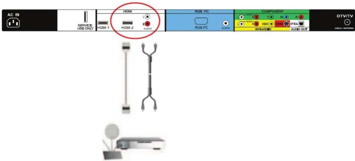
Connecting your DVD Player (Best):

text_image
AC IN SERVICE USE ONLY HDMI L RGB PC COMPONENT DTV/TV CABLE / ANTERNA HDMI 1 HDMI 2 AUDIO RGB PC AUDIO AVIS/VIDEO AUDIO OUT 1. Turn off the power to the HDTV and DVD player. 2. Connect a HDMI cable to the HDMI output of your DVD player and the other end to the HDMI Input (wh color area) at the rear of the HDTV. 3. Turn on the power to the HDTV and DVD player. 4. Select HDMI using the INPUT button on the remote or side of the HDTV, or directly by pressing the HI button on the Remote Control.For DVD Players with DVI:
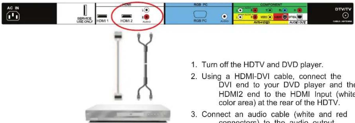
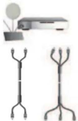
text_image
AC IN SERVICE USE ONLY HDMI HDMI 1 HDMI 2 L R AUDIO RGB PC RGB PC AUDIO COMPONENT AUDIO VIDEO AUDIO OUT DTV/TV CABLE / ANTERIOR 1. Turn off the HDTV and DVD player. 2. Using a HDMI-DVI cable, connect the DVI end to your DVD player and the HDMI2 end to the HDMI Input (white color area) at the rear of the HDTV. 3. Connect an audio cable (white and red connectors) to the audio outputconnectors associated with the DVI output of the DVD player and connect the other end to the audio connectors by the HDMI input (white area) at the rear of the HDTV.
- Turn on the power to the HDTV and your DVD player.
- Select HDMI2 using the INPUT button on the remote or side of the HDTV, or directly by pressing the HDMI button on the Remote.
Note: Refer to your DVD player user manual for more information about the video output requirements of the product.
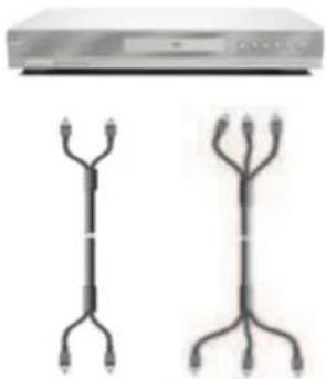
2.5.2 Using Component Video
Connecting your DVD Player (Better):
natural_image
Two electronic devices with three vertical connectors, one front view and one side view (no text or symbols visible)
text_image
AC IN SERVICE USE ONLY HDMI HDMI 1 HDMI 2 R A-2/00 RGB PC RGB PC AUDIO COMPONENT L T P h L VISO MISO OPTAL AVS/VIDEO AUDIO OUT DTV/TV CABLE ANTENZA- Turn off the power to the HDTV and DVD player.
- Connect the Y (green color) connector on your DVD player to the corresponding Y (green color) connector in the Component input (green color area - row of connectors nearest to you when viewing from the rear of the TV) at the rear of the HDTV.
- Connect the Pb (blue color) connector on your DVD player to the corresponding Pb (blue color) connector in the Component input (green color area - row of connectors nearest to you when viewing from the rear of the TV) at the rear of the HDTV.
- Connect the Pr (red color) connector on your DVD player to the corresponding Pr (red color) connector in the Component input (green color area - row of connectors nearest to you when viewing from the rear of the TV) at the rear of the HDTV.
- Using an audio cable (white and red connectors), connect the cable to the audio output connectors associated with the Component output on your DVD player and connect the other end to the audio connectors associated with the Component input (green color area) at the rear of the HDTV.
- Turn on the power to the HDTV and DVD player.
- Select Component using the INPUT button on the remote or side of the HDTV, or directly by pressing the Component button on the Remote Control.
Note: Refer to your DVD player user manual for more information about the video output requirements of the product.
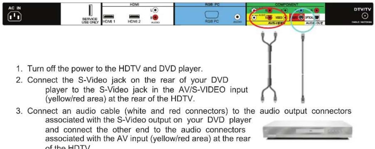
2.5.3 Using S-Video (AV/S-VIDEO)
Connecting your DVD Player (Good):
text_image
AC IN SERVICE USE ONLY HDMI HDMI 1 HDMI 2 L R AUDIO RGB PC RGB PC AUDIO COMPONENT AV/S-VIDEO VIDEO OPTICAL AUDIO/OUT DTV/TV CABLE/ADDITIONS 1. Turn off the power to the HDTV and DVD player. 2. Connect the S-Video jack on the rear of your DVD player to the S-Video jack in the AV/S-VIDEO input (yellow/red area) at the rear of the HDTV. 3. Connect an audio cable (white and red connectors) to the audio output connectors associated with the S-Video output on your DVD player and connect the other end to the audio connectors associated with the AV input (yellow/red area) at the rear of the HDTV.-
Turn on the power to the HDTV and DVD player.
-
Select AV using the INPUT button on the remote or side of the HDTV, or directly by pressing the AV button on the Remote Control.
2.5.4 Using Composite (AV) Video Input
Connecting your DVD Player (Good) :

text_image
AC IN SERVICE USE ONLY HDMI L1 HDMI 1 HDMI 2 R3 AUDIO RGB PC RGB PC AUDIO COMPONENT AUDIO VIDEO R3 AUDIO OUT DTV/TV CABLE/ANTennaTurn off the power to the HDTV and DVD player.
- Connect the Video (yellow color) connector on your DVD player to the Video (yellow color) connector in the AV/S-VIDEO input (yellow/red color area - row of connectors furthest from you when viewing from the rear of the HDTV) at the rear of the HDTV.
- Connect the R (red color) and L (white color) audio connectors on your DVD player to the corresponding R (red color) and L (white color) audio input connectors in the AV input (yellow/red color area - row of connectors furthest from you when viewing from the rear of the TV) on the rear of the HDTV.

natural_image
Illustration of a vertical tree-like structure above a rectangular electronic device (no text or symbols visible)-
Turn on the power to the HDTV and DVD Player.
-
Select AV using the INPUT button on the remote or side of the HDTV, or directly by pressing the AV button on the Remote Control.
Note: Refer to your DVD player user manual for more information about the video output requirements of the product.
2.6 Connecting Your VCR or Video Camera

text_image
AC IN SERVICE USE ONLY HDMI L HDMI 1 HDMI 2 AUDIO RGB PC AUDIO COMPONENT AUDIO R V LED T Digital AUDIO AUDIO OUT DTV/TV CABLE LANOMICS- Turn off the HDTV and VCR or Video Camera.
- Connect the S-Video jack on the rear of your VCR or Video Camera to the S-Video jack in the AV input (yellow/red area) at the rear of the HDTV.
- Connect an audio cable (white and red connectors) cable to the audio output connectors associated with the S-Video output on your VCR or Video Camera and connect the other end to the audio connectors associated with the AV input (yellow/red area) at the rear of the HDTV.
- Turn on the power to the HDTV and VCR or Video Camera.
- Select AV using the INPUT button on the remote or side of the HDTV, or directly by pressing the AV button on the Remote Control.
natural_image
Two vertical connectors with connecting lines above a white electronic device (no visible text or symbols)Note: Refer to your VCR or Video Camera user manual for more information about the video output requirements of the product.
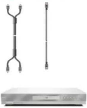
2.7 Connecting an external Receiver/Amp
2.7.1 Optical Output of Audio received
If your sound system has a SPDIF (optical) digital audio input you can connect it to the optical AUDIO OUT (white area) at the rear of the VO22L FHDTV10A.
text_image
AC IN SERVICE USE ONLY HDMI HDMI 1 HDMI 2 L R AUDIO RGB PC COMPONENT AUDIO T1 P3 Pr L AUDIO VIDEO HEDD OPTICAL AVISA/VIDEO AUDIO OUT DTV/TV CABLE C/ANTERMS 1. Turn off the power to the LCD HDTV and Receiver/Amp. 2. Using an SPDIF cable, connect the cable to the audio input connector on the Receiver/Amp and connect the other end to the OPTICAL OUT (white area) audio connectors at the rear of the LCD HDTV.- Turn off the power to the LCD HDTV and Receiver/Amp.
-
Using an SPDIF cable, connect the cable to the audio input connector on the Receiver/Amp and connect the other end to the OPTICAL OUT (white area) audio connectors at the rear of the LCD HDTV.
-
Turn on the power to the LCD HDTV and Receiver/Amp.
-
Then press the button on the remote control to open the On-Screen Display (OSD) menu.
-
Press the 📋 on the remote control to select the Audio Adjust menu.
-
Press the on the remote control to select SPEAKERS.
-
Press the on the remote control to select OFF so that the sound from the LCD HDTV will now be routed through your Receiver/Amp system.

bar
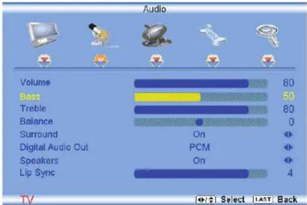
Audio | Component | Rating | |---|---| | Volume | 80 | | Bass | 50 | | Treble | 80 | | Balance | 0 | | Surround | On | | Digital Audio Out | PCM | | Speakers | On | | Lip Sync | 4 |Press the LAST key once to return to the previous screen or repeatedly to return to your program if task has been completed.
Note:
a) Refer to your Receiver/Amp user manual to select the corresponding audio input.
b) The audio output is not amplified and cannot be connected directly to external speakers.
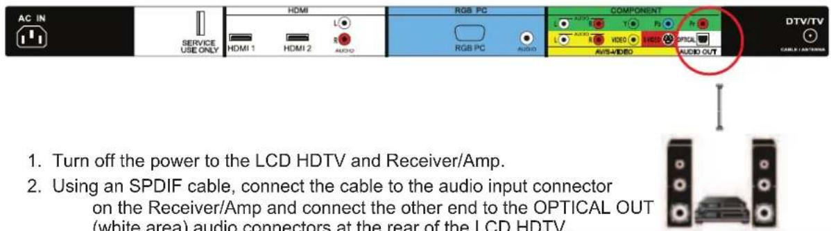
2.8 Connecting a PC Computer
text_image
AC IN SERVICE USE ONLY HDMI L HDMI 1 HDMI 2 AUDIO RGB PC COMPONENT AUDIO VIDEO HDTV/TV CABLE / ANTERIOR RGB PC AUDIO AVIS-VIDEO AUDIO OUT 1. Turn off the power to the HDTV and PC Computer. 2. Connect a 15-pin D-Sub RGB (VGA) cable to the RGB output of your pc computer and the other end to the RGB PC input (blue area) at the rear of the HDTV. 3. Connect the Audio Out on your pc computer to the RGB PC Audio input (blue area) at the rear of the HDTV. 4. Turn on the HDTV and PC Computer- Select RGB using the INPUT button on the remote or side of the HDTV, or directly by pressing the RGB button on the Remote Control.
Note:
a) For the best picture quality when connecting a pc computer through RGB PC, set your pc computer timing mode to VESA 1920x1080 at 60Hz. Please refer to the pc or graphic card's user guide for additional information on how to set the timing mode and the video output requirements of the product.
b) A RGB (VGA) cable and stereo mini jack cable are not included and can be purchased at an electronics store.
2.8.1 Preset PC Resolutions
If connecting to a PC through the RGB PC input, set the TV timing mode to VESA 1920x1080 at 60Hz for best picture quality (refer to the graphic card's user guide for questions on how to set this timing mode). Please see the table below for the factory preset resolutions.
| Resolution | Refresh (Hz) | H.Freq (kHz) | V.Freq (Hz) | H.Sync V. | Sync Pixel | Freq (MHz) |
| 640x480 60 | 31.5 59.9 | 4 N N 25. | 175 | |||
| 640x480 75 | 37.5 75 | N N | 31.5 | |||
| 720x400 | 70 | 31.46 | 70.08 | N | P | 28.32 |
| 800x600 60 | 37.9 | 60.317 P | P | 40 | ||
| 800x600 | 75 | 46.9 | 75 | P | P | 49.5 |
| 800x600 85 | 53.7 85.0 | 6 P | P | 56.25 | ||
| 1024x768 | 60 48.4 | 60.01 N | N | 65 | ||
| 1024x768 | 75 | 60 | 75.03 | P | P | 78.75 |
| @1920x1080 | 60 | 66.65 | 59.99 | P | P | 136.5 |
NOTES: N = Negative, P = Positive, @ = Primary (Native) Mode
2.8.2 Resolution (1920x1080) through RGB (15-Pin VGA) Input
If your PC supports VESA Reduce Blanking timing via the VGA card drive program (usually offered by the VGA Card Manufacturer), your TV set is equipped to have the 1920X1080 resolution display through this connection using the following timing 136.5MHz. The following parameters are often the values required by the software or programs to set up the display:
| Parameters | Horizontal Values (Pixels) | Vertical Values (Lines) |
| Address | 1920 | 1080 |
| Front Porch | 32 | 1 |
| Sync Width | 32 | 3 |
| Back Porch | 64 | 27 |
| Total | 2048 | 1111 |
| Frequency | 66.7 kHz | 60 Hz |
| Sync Polarity | P | P |
| Pixel Rate (MHz) | 136.5 | |
| Refresh Rate (Hz) | 60 |
Setting Up to Watch Television
For 'Preparing Your LCD HDTV for Wall Mounting', see page 8.
2.9 Basic LCD HDTV Start Up
1. Connecting the Power Cable
Connect the power cord to the power cord connector on the back of the HDTV, and then plug the power cord into an AC wall socket.
2. Connect Audio and Video Cables to the HDTV
(see pages 17 \~ 29 for detailed steps)
3. Turning Power On
Once all the components are connected, press the Power ON button on the side of the HDTV, or press the Power ON (Red) button on the remote control.

text_image
Initial Setup Welcome Allow the VIZIO Setup Wizard to help you tune your channels. Next LAST Exit4. Initial Setup
After powering on the TV set, the Initial Setup screen will come up.
Press the 📋 button on the remote control.
a. The Language choice screen will be displayed; the default English option is highlighted. If you wish to change the OSD language to Español or Français, press the button on the remote control to select the language you want. Press the button on the remote to go to the next screen.

text_image
Initial Setup Language Please select your language: English Españ! Français Back Select Next LAST ExitNote: At this point, if a Set-Top Box from your Local Cable or Satellite Service Company or other equipment is been used; please press the LAST key on the remote control and go to Step 5. If this is not your case, please continue at Step b.
b. The Tuner screen will be displayed; default choice is Antenna. If you are using Cable, press the button to highlight CABLE.
Press the 📋 button on the remote to go to the next screen.
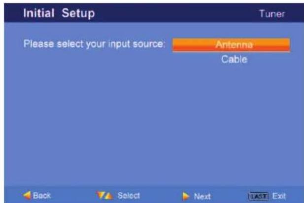
text_image
Initial Setup Tuner Please select your input source: Antenna Cable Back Select Next LAST Exitc. The Channel Scan screen will be displayed; default choice is Scan. Press the 📋 button on the remote control to commence the search for available channels to be stored into memory.
If you do not want to scan for channels at this time, press the LAST key on the remote control.

text_image
Initial Setup Channel Scan Please connect your cable or antenna to the DTV/TV input. Scan Skip Scan 0% Back Select Next LAST ExitNote: If you select to skip this step by pressing the LAST key, next time that you decide to complete this procedure, you will need to select the TV as input (through the Input key) and then go through the Menu option, and select the Tuner setup to get the option of scanning the channels again.
d. The screen will now change to show the progress of the search for Analog (NTSC) and Digital (ATSC) channels.
Note: DTV digital broadcast is not available in all areas. Refer to www.antennaweb.org for information about availability in your area, type of antenna and in which direction to point your antenna. The channel availability through cable depends upon which channels your cable operator supplies in Clear QAM; consult your cable operator for more information.
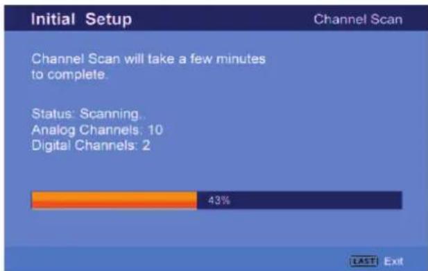
bar
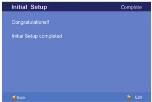
| Initial Setup | Percentage | | -------------- | ---------- | | Channel Scan | 43% | | Status: Scanning | - | | Analog Channels | 10 | | Digital Channels | 2 |e. When finished, the Complete screen will be displayed to inform you that the HDTV has completed the Initial Setup.
Press the 📋 button on the remote control to exit and begin watching TV.
text_image
Initial Setup Congratulations!! Initial Setup completed. Back Exit5. Select Input Source
Select the Input Source for the HDTV by pressing the INPUT button on the side of the TV or using the Input button on the remote control. Pressing this button will cycle you through the following options: TV, AV (S-VIDEO), Component, RGB, and HDMI.
Now follow the procedure below to display channels from a different signal (External TV Tuner, VCR, Cable Box or Satellite Receiver) source, using different inputs at the back of you TV set.
| Input |
| TV |
| AV |
| COMPONENT |
| RGB |
| HDMI1 |
| HDMI2 |
a. Select the correct input connection; RF (DTV/TV)
connector, Composite (Yellow, Red and White)
connectors, Component (Red, Green, Blue plus Red and White) connectors, HDMI connectors or Separate-Video (S-Video) plus Red and White connectors (if applicable). Make the physical connection or hook up.
b. If you have an HD service you must use the HDMI (best) or Component (better) connection.
Note: Composite (AV) and S-Video Cables can only be used for SD (480i) pictures.
c. Turn on your Cable Box, VCR, External TV Tuner or Satellite Receiver and you will see a picture on your TV set. If there is not picture, make sure you have selected the correct input on the TV set.
d. If the selected input is RF, please be aware that the TV set needs to be on either channel 3 or channel 4 matching the channel which has been selected on the back of the VCR, Cable Box, External TV Tuner or Satellite Receiver; please refer to Owner or User's Manual of such equipment for details.
Note: The TV set will be displaying any television station or program selected by the Cable Box, VCR, External Tuner or Satellite Receiver. The TV set will not be able to change programs or channels; this is controlled by the equipment sending the signal. If the service being used is the one which setup includes a box with two different outputs for two different (distant) rooms, then scanning channels would help you to find the signal. Be aware that the channel to be selected varies from provider to provider; meaning that, you may have to call your provider company so they could provide you the specific channel when using high definition made TV sets. Some examples of these channels are: 105, 106, 115 and 116.
6. Fine Tuning your TV set for Home Use.
After completing Procedure 4 or Procedure 5; please follow the steps below to optimize your TV set display:
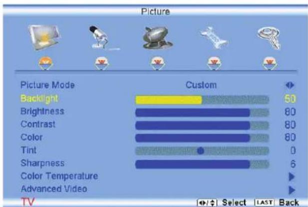
a. Press the 🎨 key to bring up the Menu display. Use the 🔊 or 📣 button to scroll to the Color Temperature option.

text_image
Picture Picture Mode Custom Backlight 50 Brightness 80 Contrast 80 Color 80 Tint 0 Sharpness 6 Color Temperature Advanced Video TV MENU Enter Select LAST Back
text_image
Color Temperature Color Temperature Custom Red 128 Green 128 Blue 128 TV Select LAST Backb. Press the 📋 button to select it.
c. Press either 📁 or 📌 button to change setting to Normal, and then press the LAST key again to go back to previous screen.
d. Press either ▲ or ▼ button to select the Picture Mode option.
bar
Picture | Picture Mode | Custom | | :--- | :--- | | Backlight | 50 | | Brightness | 80 | | Contrast | 80 | | Color | 80 | | Tint | 0 | | Sharpness | 6 | | Color Temperature | ▶ | | Advanced Video | ▶ | TV Select LAST Back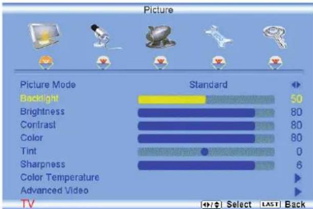
bar
Picture | Picture Mode | Standard | | :--- | :--- | | Backlight | 50 | | Brightness | 80 | | Contrast | 80 | | Color | 80 | | Tint | 0 | | Sharpness | 6 | | Color Temperature | ▶ | | Advanced Video | ▶ | TV Select LAST Backe. Press either 📄 or 📋 button to change the Picture Mode option to Standard.
f. Press the LAST key to exit the on screen display Menu.
Note: If Procedure 4 had been done, you would like to do the following to ensure that the correct program times are shown when pressing the Guide key:
Press the ⬤ key, this will bring up the picture mode
Press either 📄 or 📋 button scroll across to the icon showing the little satellite dish or antenna. The next screen will appear showing Time Zone.
Press either ▲ or □ button to select it.
Press either 📄 or 🔊 button to choose the proper Time Zone of your area.
Press the LAST key once to return to the previous screen or repeatedly to return to your program if task has been completed.

text_image
Tuner Mode Auto Search Skip Channel MTS Time Zone Daylight Saving Antenna Stereo Eastern On Select LAST BackYour new TV set is now ready to automatically reproduce the best picture quality out of the input signal which is been fed into it. Enjoy your TV watching!!
2.10 Watching a TV Program
Before you start watching TV, please make sure that any cable, satellite or off-air antenna connections are secure. Also, verify that the power cord is plugged into a correctly grounded electrical outlet or surge protector.
- Press the power button on the remote or on the side of the HDTV. The VIZIO logo on the front will change from orange to white.
- There are 3 options for selecting your programming:
a. If you are using an antenna or cable connected through the DTV/TV CABLE/ANTENNA input, you can select TV directly by pressing the TV button on the remote, or by pressing the INPUT button on the remote or on the side of the HDTV.
b. If you are watching broadcasts through a cable or satellite set-top box connected by an HDMI cable, select HDMI directly by pressing the HDMI button on the remote, or by pressing the INPUT button on the remote or on the side of the HDTV.
c. If you are watching broadcasts through a cable or satellite set-top box connected by a Component (YPbPr) cable, select Component directly by pressing the Component button on the remote, or by pressing the INPUT button on the remote or on the side of the HDTV.
Note: You should be able to see a picture. If you do not, make sure that all of the HDTV connections are secure and you have selected the correct video input source.
- When using option 2a, press the Channel buttons on the remote or the CH +/- buttons on the side of the HDTV to change the channel. Note: The Channel buttons, on the side of the HDTV and on the remote, control will not work if you are watching a program using HDMI, Component, AV-S (S-Video) and AV-C (Composite) inputs.
2.11 Adjusting Basic HDTV Settings
text_image
GUIDE HOME RUNT TV COMP LAST RV CH V CH 1 2 3 4 5 6 7 8 9 INPUT 0 - VIZIOVolume
To increase the volume, press and hold the VOL+ or VOL- button on the side of the LCD HDTV or remote control until the desired level is reached.
TV Channels
To step up or down through the available TV channels, press the CH+ or CH- button on the side of the HDTV or remote control once for the next or previous channel, or hold it depressed until the desired channel is reached. Note: Channel up and down will only operate in DTV and TV modes.
Wide
Using this feature, you can watch video content in different size modes on the HDTV.
Press the button on the remote control
to bring up the OSD screen.
Press either the < or > button to select Setup (wrench look alike icon) options.
Press the button scroll down to Wide and select it.
Press either the < or button to select among the modes.
Fore more information see Section 3.17.1 – Viewing Modes, on page 64.

text_image
MENU CH+ CH- VOL+ VOL- INPUT
natural_image
Computer monitor with a red oval highlight on the side panel, showing no text or symbols.2.12 Program Information
Press the GUIDE button twice on the remote and program information for the channel you are watching will be displayed on the screen with the live program content in a small window in the lower left corner.

text_image
Sunday, 26-June-2005 11:02:48 PM 20 20-1 KBWB-HD ▶ 20-2 Today 11:00 PM Charmed Tomorrow 12:00 AM Steve Harvey's Big Time Challenge Tomorrow 1:00 AM Angel Tomorrow 2:00 AM Cheaters Tomorrow 3:00 AM Distortion 2 Static 11:00 PM - 12:00 AM Sun, 26-Jun TV-14-V Zankou taps the services of the insidious Alchemist (John Kassir) to weaken the nerves of the sisters in a ploy to gain control of the Book of Shadows. Meanwhile, Darryl struggles 1/2Press the 📄 or 📋 button to scroll up or down the channels. Each time you pause at a channel, the program list will update with the program schedule for the channel and the window will show the live program for that channel. Press the GUIDE button to exit this feature.
2.13 Information on HDTV Status
When you change TV channels or inputs, or press the GUIDE button once on the remote, an Information Banner is displayed for a few seconds to tell you the status of the LCD HDTV.

flowchart
graph TD
    A["Program Information: Provided by Broadcaster"] --> B["Charmed"]
    C["Audio is Stereo"] --> D["English stereo"]
    E["TV Channel Number"] --> D
    F["Station Name: provided by Broadcaster"] --> G["20-2 KBWB-SD"]
    H["Program Rating"] --> I["TV-14-V"]
    J["Closed Caption is available"] --> K["CN"]
    L["NTSC SDTV (Standard Definition TV)"] --> M["Cable"]
    N["Source is Cable"] --> O["Source"]
Chapter 3 Advanced Adjustment of HDTV
3.1 Using the On Screen Display (OSD)
The remote control or the control buttons on the right hand side of the TV can control all the function settings. The On Screen Display (OSD) allows you to adjust the save contrast, brightness and other settings. The TV will save changes made to the settings, even if the TV is turned off.
The OSD consists of several menu options: Picture Adjust, Audio Adjust, Setup, TV Tuner Setup and Parental Controls. The main menu options may very depending on your selected input source.
Note: Some of the main menu options may have additional submenus, i.e. the TV Rating submenu for Parental Controls.
- Press the

s the button on the remote control or the side of the TV and the Picture Adjust menu will be shown on the screen.
- Press the

s the or button on the remote control or the VOL + or VOL - button on the side of the HDTV to select one of the other menu options.
bar
Picture | Picture Mode | Custom | | :--- | :--- | | Backlight | 50 | | Brightness | 80 | | Contrast | 80 | | Color | 80 | | Tint | 0 | | Sharpness | 6 | | Color Temperature | ▶ | | Advanced Video | ▶ | TV MENU Enter Select LAST Back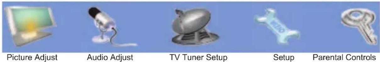
text_image
Picture Adjust Audio Adjust TV Tuner Setup Setup Parental Controls- Once the menu option is displayed, press the 📄 or 🌐 button on the remote control or the CH + or CH - button on the side of the TV to select one of the items to adjust.

text_image
Brightness 25-
Press the button on the remote control or the VOL - button on the side of the HDTV to begin adjustment of the item.
-
Press

when finished.
- Repeat steps 2 through 5 to adjust additional options within this menu.
Press the LAST key once to return to the previous screen or repeatedly to return to your program if task has been completed.
3.2 DTV / TV Input Picture Adjustment
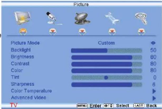
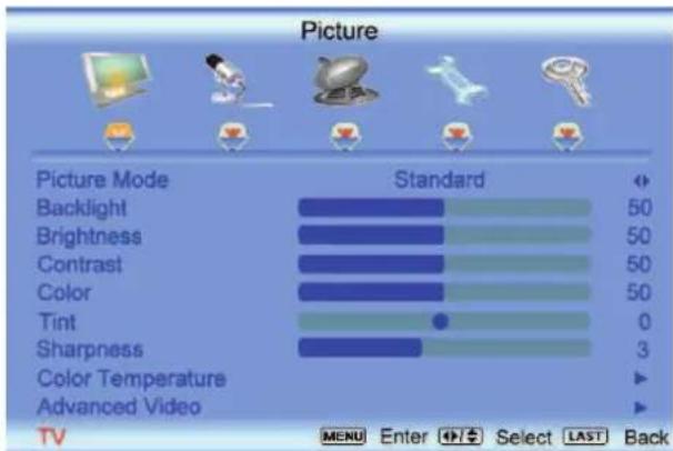
When the button is pressed, the On Screen Display (OSD) appears on the PICTURE adjustment page.
Press the button to highlight the Picture Mode selection.
Use the
or button to choose from Custom, Standard, Movie and Game.
If Standard, Movie or Game is chosen for the Picture Mode, still the Picture Adjustments are available for you to set them to your preferred settings.
text_image
Picture Picture Mode Standard Backlight 50 Brightness 50 Contrast 50 Color 50 Tint 0 Sharpness 3 Color Temperature Advanced Video TV MENU Enter Select LAST BackOnce the adjustments are completed press the LAST button repeatedly to exit the OSD completely.

text_image
Picture Picture Mode Standard Backlight 50 Brightness 80 Contrast 80 Color 80 Tint 0 Sharpness 6 Color Temperature Advanced Video TV Select LAST Back3.2.1 Backlight
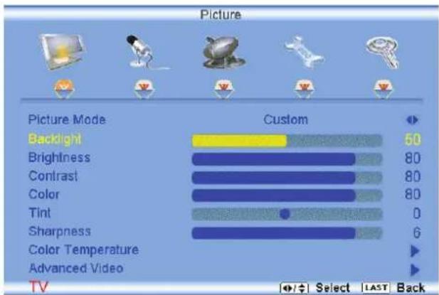
Press the button to highlight the Backlight selection.
bar
Picture | Picture Mode | Custom | | :--- | :--- | | Backlight | 50 | | Brightness | 80 | | Contrast | 80 | | Color | 80 | | Tint | 0 | | Sharpness | 6 | | Color Temperature | ▶ | | Advanced Video | ▶ | TV Select LAST BackPress the button to start adjusting the brightness of the Backlight and the menu page will disappear and be replaced by a small Backlight Indicator Bar so you can see the light level between the minimum and maximum available levels.
Use the 📄 or 📋 button to adjust the level.
Backlight

25
The Backlight level does not affect the Brightness (black level) or Contrast (white level) of the picture, it adjusts the lamp current and this affects the overall brilliance of the picture.
Once the adjustments are completed press the LAST button repeatedly to exit the OSD completely.
3.2.2 Brightness
Press the button to highlight the Brightness selection.
Press the button to start adjusting the brightness and the menu page will disappear and be replaced by a small Brightness Indicator Bar so you can see the brightness level between the minimum and maximum available levels.
Use the
or button to adjust the level.
Brightness

25
The Brightness adjusts the black levels in the picture. If the brightness is too low you will not be able to see the detail in darker parts of the picture and if the brightness is too high the picture will look washed out.
Once the adjustments are completed press the LAST button repeatedly to exit the OSD completely.
3.2.3 Contrast
Press the button to highlight the Contrast selection.
Press the button to start adjusting the contrast and the menu page will disappear and be replaced by a small Contrast Indicator Bar so you can see the contrast level between the minimum and maximum available levels.
Use the
or
Contrast

25
The Contrast adjusts the white levels in the picture. If the contrast is too low the picture will look washed out and if the contrast is too high you will not be able to see any detail in the bright parts of a picture.
Once the adjustments are completed press the LAST button repeatedly to exit the OSD completely.
3.2.4 Color
Press the 📄 button to highlight the Color selection.
Press the button to start adjusting the color and the menu page will disappear and be replaced by a small Color Indicator Bar so you can see the color level between the minimum and maximum available levels.
Use the 📄 or 📅 button to adjust the level.
Color

25
The Color adjusts the amount of color in the picture.
Once the adjustments are completed press the LAST button repeatedly to exit the OSD completely.
3.2.5 Tint
Press the Button to highlight the Tint selection.
Press the button to start adjusting the tint and the menu page will disappear and be replaced by a small Tint Indicator Bar so you can see the tint adjustment to the left or right of the nominal position.
Use the
or @ button to adjust the level.

bar
Picture | Picture Mode | Custom | | :--- | :--- | | Backlight | 50 | | Brightness | 80 | | Contrast | 80 | | Color | 80 | | Tint | 0 | | Sharpness | 6 | | Color Temperature | ▶ | | Advanced Video | ▶ | TV Select LAST BackTint

25
The Tint adjusts the hue of the picture. The easiest way to set tint is to look at flesh tones and adjust for a realistic appearance. In most cases, the default middle position is correct. If people's faces look too orange try reducing the level of color first as the case of this is often too much color.
Once the adjustments are completed press the LAST button repeatedly to exit the OSD completely.
3.2.6 Sharpness
Press the button to highlight the Sharpness selection.
Press the ➕ button to start adjusting the sharpness and the menu page will disappear and be replaced by a small Sharpness Indicator Bar so you can see the sharpness level between the minimum and maximum available levels. Use the ➕ or ➕ button to adjust the level.

text_image
Sharpness 3The Sharpness adjusts the sharpness of the picture.
Once the adjustments are completed press the LAST button repeatedly to exit the OSD completely.
3.2.7 Color Temperature
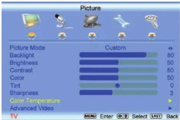
Press the button to highlight the option for Color Temperature selection.
The default is COOL; this is the 9300K setting.
Press the 📄 or 📋 button if you want to choose the Normal, Warm or Custom option.
bar
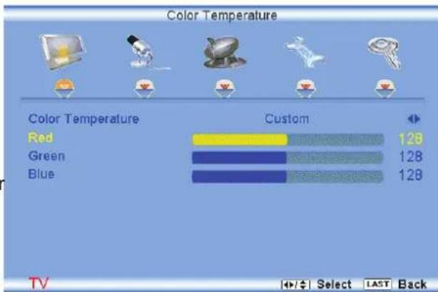
Picture | Picture Mode | Custom | | :--- | :--- | | Backlight | 80 | | Brightness | 50 | | Contrast | 50 | | Color | 50 | | Tint | 0 | | Sharpness | 3 | Color Temperature ▶ Advanced Video ▶ TV MENU Enter Select LAST BackIf you choose the Custom option, then a new menu will be displayed showing the primary color items, Red, Green and Blue.
Press the button to highlight the color you wish to adjust.
Press the button to start adjusting the color and the menu page will disappear and be replaced by a small Color (Red, Green or Blue) Indicator Bar as before.
Use the 📄 or 🎋 button to adjust the color.
Press the button when finished. Repeat the procedure to adjust the other colors if desired.
text_image
Color Temperature Color Temperature Custom Red 128 Green 128 Blue 128 TV Select LAST Back3.2.8 Advanced Video
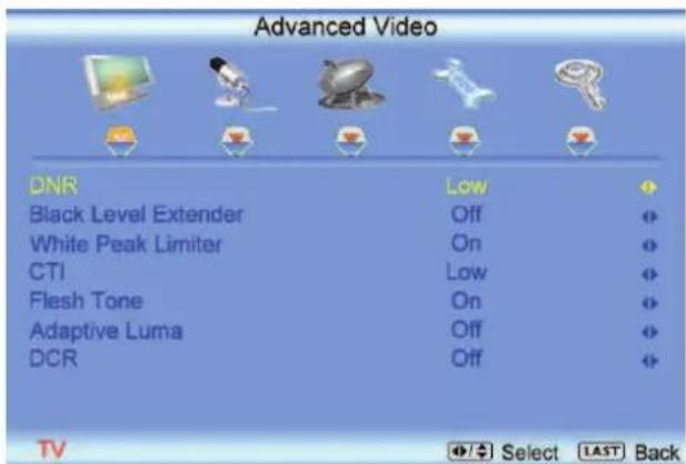
Press the 🎨 button to highlight the option for Advanced Video selection and press either the or button to select it. A new menu will be displayed showing the advanced functions available for fine tuning of the picture.
DNR
Press the 🎨 button to highlight DNR (Dynamic Noise Reduction). Use this feature to diminish picture artifacts caused by the digitizing of image motion content that may be present in the picture. Press the 🎨 or 🎨 button to choose from the Off, Low, Medium or Strong setting.
Once the adjustments are completed press the LAST button repeatedly to exit the OSD completely.
Black Level Extender
Press the 🎨 button to highlight Black Level Extender. Use this feature to increase the picture reproduction performance in the dark areas of the picture.
Press the <\or \ button to turn this feature On or Off.
Once the adjustments are completed press the LAST button repeatedly to exit the OSD completely.
text_image
Advanced Video DNR Low Black Level Extender Off White Peak Limiter On CTI Low Flesh Tone On Adaptive Luma Off DCR Off TV Select LAST Back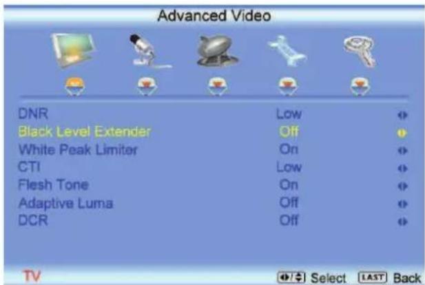
text_image
Advanced Video DNR Low Black Level Extender Off White Peak Limiter On CTI Low Flesh Tone On Adaptive Luma Off DCR OffWhite Peak Limiter
Press the button to highlight White Peak Limiter. Use this feature to limit excessive white in bright areas of the picture, caused by a lower sync level for a channel being received from the antenna or cable. Press the or button to turn this feature On or Off.
Once the adjustments are completed press the LAST button repeatedly to exit the OSD completely.

text_image
Advanced Video DNR Low Black Level Extender Off White Peak Limiter On CTI Low Flesh Tone On Adaptive Luma Off DCR Off TV Select LAST BackCTI
Press the button to highlight CTI (Color Transient Improvement). This feature can be used to reduce the time taken to transition from one color to another. The effect will be seen as sharpening the border between colors.
Press the 📄 or 📝 button to choose from the Off, Low, Medium or Strong setting.
Once the adjustments are completed press the LAST button repeatedly to exit the OSD completely.
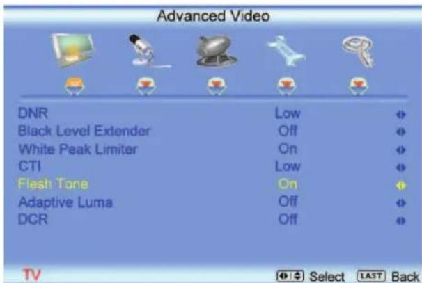
Flesh Tone
Press the 📄 button to highlight Flesh Tone. In some cases, activation of this feature can result in a more pleasing production of sky and flesh color.
Press the 📁 or 📁 button to turn this feature On or Off.
Once the adjustments are completed press the LAST button repeatedly to exit the OSD completely.
text_image
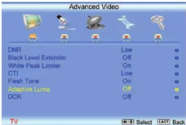
Advanced Video DNR Low Black Level Extender Off White Peak Limiter On CTI Low Flesh Tone On Adaptive Luma Off DCR OffAdaptive Luma
Press the button to highlight Adaptive Luma. Large areas of darkness in a picture will result in a lower Average Picture Level (APL) and the overall picture will look too dark; activation of this feature will raise the APL to counteract this effect.
Press the 📄 or 📝 button to turn this feature On or Off.
Once the adjustments are completed press the LAST button repeatedly to exit the OSD completely.
text_image
Advanced Video DNR Low Black Level Extender Off White Peak Limiter On CTI Low Flesh Tone On Adaptive Luma Off DCR OffDCR
Press the 📋 button to highlight Dynamic Contrast Ratio. This feature can be set to On or OFF to allow the TV set to adjust its backlight to display dark and bright scenes with a more vivid or intense quality.
Press the 📄 or 📋 button to turn this feature On or Off. Note: Backlight setting would be disabled if this option is set to On.
Once the adjustments are completed press the LAST button repeatedly to exit the OSD.

text_image
Advanced Video DNR Low Black Level Extender Off White Peak Limiter On CTI Low Flesh Tone On Adaptive Luma Off DCR Off TV Select LAST Back3.3 DTV / TV Input Audio Adjustment
3.3.1 Volume
When the button is pressed, the On Screen Display (OSD) appears on the PICTURE adjustment page.
Press the button to display the AUDIO ADJUST page.
Press the button to highlight the Volume selection.
Press the button to start adjusting the volume and the menu page will disappear and be replaced by a small Volume Indicator Bar so you can s the volume level between the zero and maximum a
Use the
or button to adjust the level.
bar
Audio | Category | Value | |---|---| | Volume | 80 | | Bass | 50 | | Treble | 80 | | Balance | 0 | | Surround | On | | Digital Audio Out | PCM | | Speakers | On | | Lip Sync | 4 |
bar
| Category | Value | |---|---| | Volume | 25 |The Volume Indicator Bar will also appear when watching a program on your TV is the Volume button on the remote or the side of the TV is pressed.
Once the adjustments are completed press the LAST button repeatedly to exit the OSD completely.
3.3.2 Bass
Press the button to highlight the Bass selection.
Press the button to start adjusting the bass and the menu page will disappear and be replaced by a small Bass Indicator Bar, as before, so you can see the bass level between the zero and maximum available levels.
Use the 📄 or 📞 button to adjust for bass boost or attenuation.

text_image
Bass 25Once the adjustments are completed press the LAST button repeatedly to exit the OSD completely.
3.3.3 Treble
Press the button to highlight the Treble selection.
Press the button to start adjusting the treble and the menu page will disappear and be replaced by a small Treble Indicator Bar, as before, so you can see the treble level between the zero and maximum available levels.
Use the □ or □ button to adjust for treble boost or attenuation.
Treble

25
Once the adjustments are completed press the LAST button repeatedly to exit the OSD completely.
3.3.4 Balance
Press the button to highlight the Balance selection.
Press the button to start adjusting the balance and the menu page will disappear and be replaced by a small Balance Indicator Bar, as before, so you can see the balance adjustment to the left or right of the nominal position.
Use the <or button to adjust the left/right balance.

bar
Audio | Category | Value | |---|---| | Volume | 80 | | Bass | 50 | | Treble | 80 | | Balance | 0 | | Surround | On | | Digital Audio Out | PCM | | Speakers | On | | Lip Sync | 4 |
Balance

0
Once the adjustments are completed press the LAST button repeatedly to exit the OSD completely.
3.3.5 Surround
Press the Button to highlight the Surround selection.
Press the button to select for the simulated surround sound feature to be On or Off.
Once the adjustments are completed press the LAST button repeatedly to exit the OSD completely.
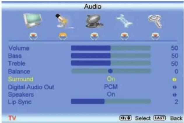
text_image
Audio Volume 50 Bass 50 Treble 50 Balance 0 Surround On Digital Audio Out PCM Speakers On Lip Sync 2 TV Select LAST Back3.3.6 Digital Audio Out
Press the button to highlight the Digital Audio Out selection.
Press the 📄 or 📋 button to make the proper selection. The options being OFF, Dolby Digital and PCM. Once the adjustments are completed press the LAST button repeatedly to exit the OSD completely.
3.3.7 Speakers
Press the Button to highlight the Speakers selection.
Press either 📄 or 🏠 button to turn the internal speakers On or Off. You may want to turn-off the internal speakers when listening to the audio through your Home Theatre System.
Press the LAST key once to return to the previous screen or repeatedly to return to your program if task has been completed.
3.3.8 Lip Sync
Included with the advanced technology of your TV, a feature which will compensate the shortcomings of signal transmission called audio sync (Lip Sync). Lip Sync is designed to adjust the audio of the program being viewed so that it matches the movement of the lips of someone talking on the screen. This feature is built into your set, and it can be applied to all inputs. To use this feature, follow the steps below.

text_image
Audio Volume 50 Bass 50 Treble 50 Balance 0 Surround On Digital Audio Out PCM Speakers On Lip Sync 0 TV Select LAST BackPress the √ key to bring up the OSD.
Using either the 📄 or 📋 button scroll across to the microphone icon, the Audio menu will be displayed.
Press either 📄 or 🔒 button to scroll either up or down to Lip Sync.
Press either or button to make the appropriated adjustment.
Press the LAST key once to return to the previous screen or repeatedly to return to your program if task has been completed.
3.4 DTV / TV Tuner Setup
When you first used your VO40L FHDTV10A you will have setup your TV for DTV / TV channels using the Initial Setup screens. If you did not do this or if your setup has changed, you can do this from the TV TUNER SETUP menu.
Once the adjustments are completed press the LAST button repeatedly to exit the OSD completely.
3.4.1 Tuner Mode
When the button is pressed, the On Screen Display (OSD) appears on the PICTURE adjustment page. Press the button to display the TV page.
Press the button to highlight the Tuner Mode selection.
Press the 📋 button to choose Cable or Air (Antenna) depending upon which equipment you have attached to the DTV / TV Input.
Once the adjustments are completed press the LAST button repeatedly to exit the OSD completely.
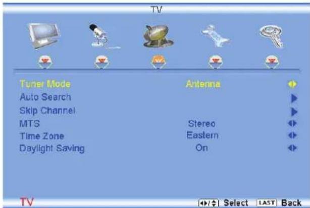
text_image
TV Tuner Mode Auto Search Skip Channel MTS Time Zone Daylight Saving Antenna Stereo Eastern On TV Select LAST Back3.4.2 Auto Search
Press the button to highlight the Auto Search selection.
Press the 📋 button to Auto Search for TV channels available. The TV will automatically search for analog and digital channels.
Once the adjustments are completed press the LAST button repeatedly to exit the OSD completely.

text_image
Auto Search Status Scanning... Analog Channel : 10 Digital Channel : 4 Cable 80% TV LAST Back3.4.3 Skip Channel
After the TV has stored all of the available DTV channels in memory you will find that some channels will be too weak to watch comfortably or they may be channels you do not want to see. Select the channel
you wish to remove, press the
Press the 📄 buttons to open the TV TUNER SETUP menu.
Press the button to highlight SKIP CHANNEL.
Press the button to select this channel to be skipped when using the CH+ or CH- button. You will still be able to select this channel using the number buttons on the remote control.
Once the adjustments are completed press the LAST button repeatedly to exit the OSD completely.
3.4.4 MTS
This feature allows you, the user to select the different languages in which the signal provider or broadcaster is transmitting the audio with the program you are watching. This signal is usually or in most cases Spanish language.
Press the button as many times as it takes to scroll down to this option and get it highlighted.
Press either
or \$button to go through the settings of this feature to make your selection.
Once the adjustments are completed press the LAST button repeatedly to exit the OSD completely.
3.4.5 Time Zone
Setting the correct Time Zone for your area will ensure that the correct program times are shown after pressing the GUIDE button on the remote control.
Press the 📋 button to highlight the Auto Search selection.
Press the ➕ button to select your area.
Once the adjustments are completed press the LAST button repeatedly to exit the OSD completely.
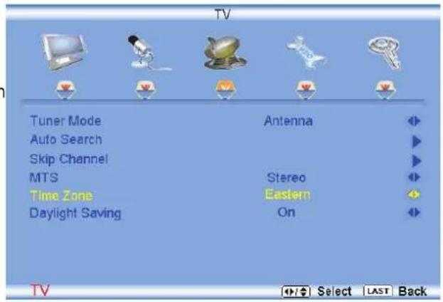
text_image
TV Tuner Mode Antenna Auto Search Skip Channel MTS Stereo Time Zone Eastern Daylight Saving On TV Select LAST Back3.4.6 Daylight Saving
As for Time Zone, setting the daylight saving time for your area will ensure that the correct program times are shown after pressing the GUIDE button on the remote control.
Press the button to highlight the Daylight Saving selection.
Press the button to select On or Off.
Once the adjustments are completed press the LAST button repeatedly to exit the OSD completely.
3.5 DTV / TV Input Setup
3.5.1 Language
When the button is pressed, the On Screen Display (OSD) appears on the PICTURE adjustment page. Press the 📄 button until the SETUP page is displayed.
Press the button to highlight the Language selection. The default is English.
Press the 📋 button to select Español or Français. Once the adjustments are completed press the LAST button repeatedly to exit the OSD completely.
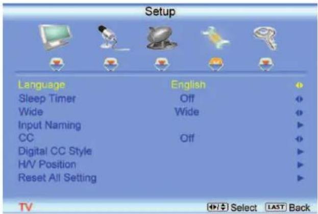
text_image
Setup Language English Sleep Timer Off Wide Wide Input Naming CC Off Digital CC Style H/V Position Reset All Setting TV Select LAST Back3.5.2 Sleep Timer
Press the button to highlight the Sleep Timer selection.
Press the button to select the timer to turn-off the TV in 30, 60, 90 or 120 minutes.
Once the adjustments are completed press the LAST button repeatedly to exit the OSD completely.
3.5.3 Wide
The Wide option is the feature which allows you to select how your display would be size wise. When in TV mode; the selections are Normal, Wide and Panoramic views.
Press the button as many times as it takes to scroll down to this option and highlight it.
Press either 📄 or 🌐 button to make the correct selection, you will see the screen adjusting to the different sizes which apply to this feature.
Once the adjustments are completed press the LAST button repeatedly to exit the OSD completely.
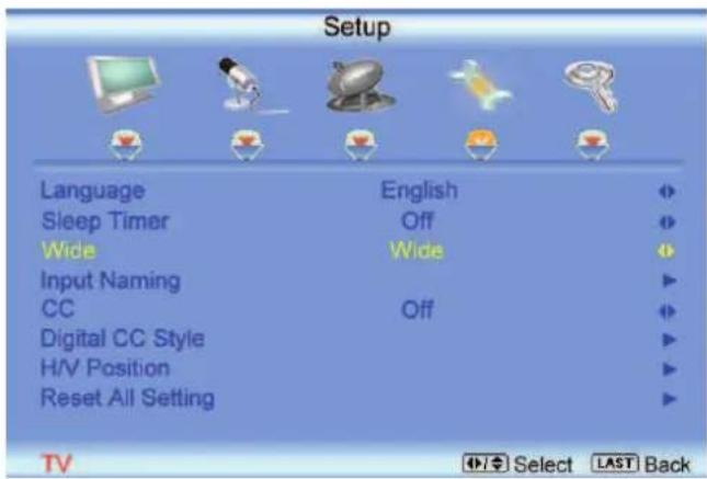
text_image
Setup Language English Sleep Timer Off Wide Wide Input Naming CC Off Digital CC Style H/V Position Reset All Setting TV Select LAST Back3.5.4 Input Naming
This feature has been added to facilitate you, the user in identifying or label the input and signal which is being watched. You could use up to 8 characters; either letters or numbers or combinations of both.
Press 📋 button to highlight this option.
Press 📋 button to obtain the next screen which shows the different inputs.
Press 📋 button to select the desired input which you want to label or name (Examples: VCR, DVD,..., etc.) it with any name which will make easier for you to recognize it.
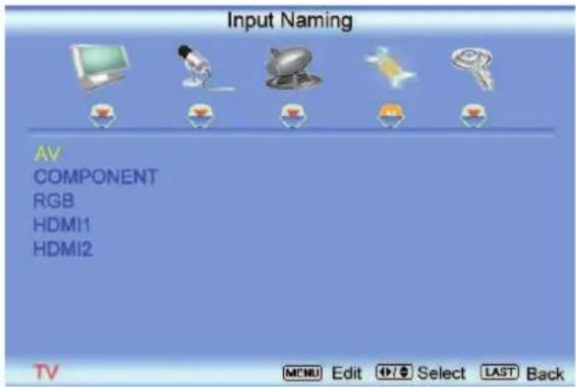
text_image
Input Naming AV COMPONENT RGB HDMI1 HDMI2 TV MENU Edit Select LAST Back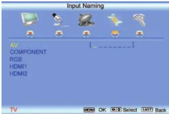
text_image
Input Naming AV COMPONENT RGB HDMI1 HDMI2 - - - - - - - - - - - - - - - - - - - - - - - - - - - - - - - - - - - - - - - - - - - - - - - - - - - - - - - - - - - - - - - - - - - - - - - - - - - - - - - - - - - - - - - - - - - - - - -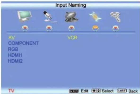
text_image
Input Naming AV COMPONENT RGB HDMI1 HDMI2 VCR TV MENU Edit Select LAST BackPress the LAST key once to return to the previous screen or repeatedly to return to your program if task has been completed.
Press the V key to go to the first space (_) in the bracket.
Press either the 📄 or 🕒 button and select either the letter or number belongs to this place.
Press the 📋 button to go to the next space (_) and again
Using either the 📄 or 📋 button select the second character of the name given to this Input.
Repeat the last previous two steps until the name of the input is completed.
Press the 📋 key to accept the name of the input or the LAST key to cancel the setting. .
Press the LAST key when you have finished to go to the previous menu.
Since you are already in this feature; it is recommendable to name all the Inputs which are being used as well as these for which you have an idea what their name is going to be.
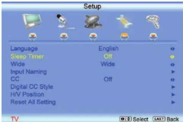
text_image
Setup Language English Sleep Timer Off Wide Wide Input Naming CC Off Digital CC Style H/V Position Reset All Setting TV Select LAST Back3.5.5 Analog Closed Caption
When watching regular analog (NTSC) TV, the Analog CC feature is available in the Setup menu.
Press the button to highlight the Analog CC selection.
Press the 📋 button to select CC1, CC2, CC3 or CC4.
Once the adjustments are completed press the LAST button repeatedly to exit the OSD completely.
Closed Caption for regular TV is usually CC1 or CC2.
3.5.6 Digital Closed Caption
When watching DTV, the Digital CC Style feature is available in the Setup menu.
Press the 📋 button to highlight the Digital CC Style selection.
Press the button to go to the next screen.
Press either
or \$ button to toggle between the two options; As Broadcaster and Custom.
If Custom is selected then you will have the way of customize the way Closed Caption will be displayed by changing these different parameters
to your like: Font Size (letters size), Font Color
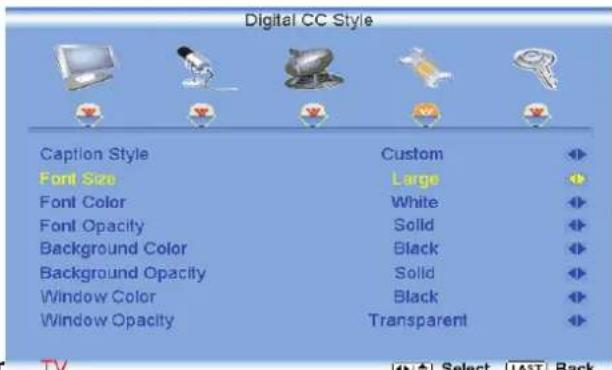
text_image
Digital CC Style Caption Style Custom Font Size Large Font Color White Font Opacity Solid Background Color Black Background Opacity Solid Window Color Black Window Opacity Transparent(letters color) Font Opacity (transparency of the letters), Background Color (color of the background area where Closed Caption is going to be displayed), Background Opacity (allows to either see through at the scene being played or it could be a solid screen), Window Color (it gives the color to the area where characters will be displayed on) and finally Window Opacity (allows the area to be of the characters to be changed). There are no recommendations of setting these parameters since you, the user would have your own taste or like of them.
Press the key labeled LAST as many times as it takes to exit the menu screens.
3.5.7 Reset All Settings
Press the button to highlight the Reset All Settings selection.
Press the 📋 button to reset the TV to the default factory settings.
Once the adjustments are completed press the LAST button repeatedly to exit the OSD completely.
Note: This does NOT reset the Parental Control Password.
3.6 DTV / TV Input Parental Control
3.6.1 Channel Block
If you want to restrict certain channel and program viewing, you can do this by turning on the Parental
Control. Selected programs, movies and channels can then be made available only after an authorized password has been entered and accepted by the TV.
When the button is pressed, the On Screen Display (OSD) appears on the PICTURE adjustment page.
Press the button to display the PARENTAL page.

text_image
Parental Password TV Select LAST BackThe Password must be entered before the TV will continue with Parental settings. The default password set in the factory is 0 0 0 0. If you are going to use the Parental Control feature you should change the password.
Note: Make sure you write down and store the new password in a secure place. The Reset All Settings feature (see page 53) does NOT reset the password.
Press the button to highlight the Channel Block selection.
Press the button to turn it on or off. Once the adjustments are completed press the LAST button repeatedly to exit the OSD completely.

text_image
Parental Channel Block US TV Rating US Movie Rating Canadian English Rating Canadian French Rating Check for New DTV Rating Block TV Unrated No Access Code Edit TV MENU Enter Select LAST Back3.6.2 TV Rating
Follow the procedure in the previous section 3.6.1 to display the Parental Control menu and then press the button to highlight the TV Rating selection.
Press the button and the Block TV Rating panel will be displayed.
In the Block TV Rating panel you can customize the program blocking of the following TV ratings:
Y - All children
Y7 – Older children
G – General audience
PG – Guidance suggested
14 – Strongly cautioned
MA – Mature audience
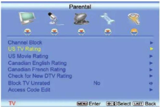
text_image
Parental Channel Block US TV Rating US Movie Rating Canadian English Rating Canadian French Rating Check for New DTV Rating Block TV Unrated No Access Code Edit TV MENU Enter Select LAST BackYou can also customize the TV ratings for the following content:
A – All subratings
D – Sexual dialog
L – Adult language
S – Sexual situations
V - Violence
FV – Fantasy violence
Press the 🔒 or 📋 button to navigate through the TV rating options.
Press the button to block (locked) or allow (unlocked).
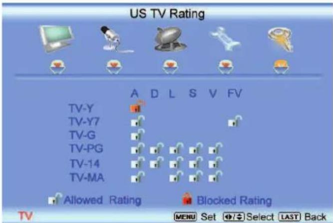
text_image
US TV Rating TV-Y TV-Y7 TV-G TV-PG TV-14 TV-MA A D L S V FV Allowed Rating Blocked Rating MENU Set Select LAST Back3.6.3 Movie Rating
Press the 📄 button to highlight the Movie Rating selection.
Press the button and the Block Movie Rating panel will be displayed.
In the Block Movie Rating panel you can customize the program blocking of the following Movie ratings:
G - General audience
PG – Parental guidance suggested
PG-13 – Recommended for children 13 years of age or older
R - Mature audience
NC-17 – No one under 17 years of age
X – No one under 17 years of age
Press the 📁 or button to navigate through the Movie rating options.
Press the button to block (locked) or allow (unlocked).

text_image
US Movie Rating G PG PG-13 R NC-17 X Allowed Rating Blocked Rating TV MENU Set Select LAST Back3.6.4 Check for New DTV Rating
This option is designed to update the TV or Movie table of different ratings for programs being viewed in your local or regional area. It will allow the parental guidance control feature in your TV to have the most current parental control database for a digital signal. This option may be available in the future for activation. This option works as follows: Whenever you decide to use the Parental Control feature and this option has been activated in your area, the Check for New DTV Rating will be a solid color indicating that an update is available for the TV Rating or Movie Rating table. After entering the password, the Parental menu will appear on the screen, and then do the following.
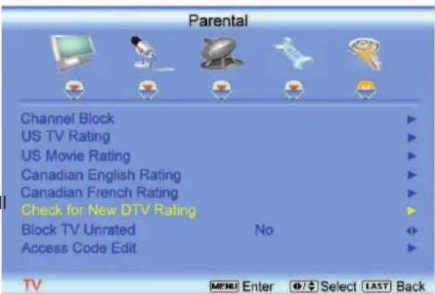
text_image
Parental Channel Block US TV Rating US Movie Rating Canadian English Rating Canadian French Rating Check for New DTV Rating Block TV Unrated No Access Code Edit TV MENU Enter Select LAST BackObserve the status of the Check for New DTV Rating. If option is faded out, no update is available (the option is not activated in your area). If it is not faded out,
press either 📂 or button to select this option.
Press button to execute this operation. Please follow the on screen instructions to complete this procedure.
Press either ▲ or □ to select and then adjust any other option in this menu.
Press the LAST key once to return to the previous screen or repeatedly to return to your program if task has been completed.
3.6.5 Blocked Unrated Programming
Follow the procedure in the previous section 3.6.1 to display the Parental Control menu and then press the button to highlight the Block Unrated TV selection.
Press the ➕ button to turn-on or turn-off the blocking of programming that does not have a rating.
Once the adjustments are completed press the LAST button repeatedly to exit the OSD completely.

text_image
Parental Channel Block US TV Rating US Movie Rating Canadian English Rating Canadian French Rating Check for New DTV Rating Block TV Unrated No Access Code Edit TV Select LAST Back3.6.6 Change the Password
Press the button to highlight the Access Code Edit selection.
Press the button and the new Password panel will be displayed.
Enter the new, 4-digit password using the number buttons on the remote. Enter it a second time confirm you entered it correctly.
Once the adjustments are completed press the LAST button repeatedly to exit the OSD completely.
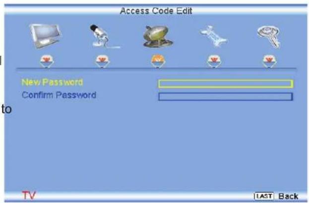
text_image
Access Code Edit New Password Confirm Password to TV LAST BackNote: Make sure you write down and store the new password in a secure place. The Reset All Settings feature (see page 53) does NOT reset the password.
3.7 HDMI Input Picture Adjustment
The Picture Adjust menu operates in the same way for the HDMI Input as for the DTV / TV input in section 3.2. The menu difference is that there no icon along the top for DTV / TV or Parental Control adjustments.
Once the adjustments are completed press the LAST button repeatedly to exit the OSD completely.
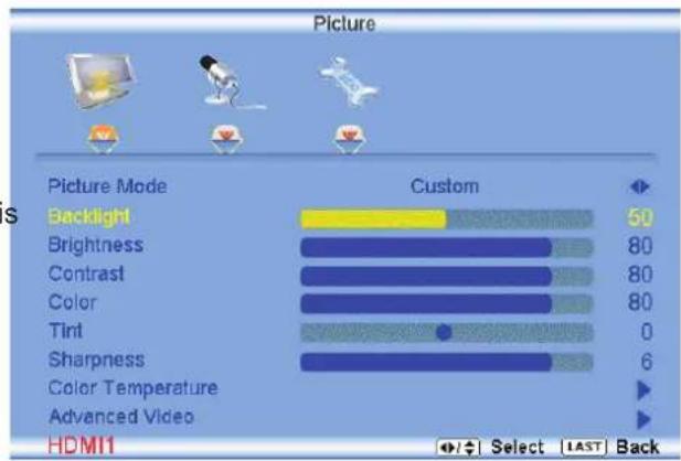
text_image
Picture Picture Mode Custom Backlight 50 Brightness 80 Contrast 80 Color 80 Tint 0 Sharpness 6 Color Temperature Advanced Video HDMI1 Select LAST Back3.8 HDMI Input Audio Adjustment
The Audio Adjust menu operates in the same way for the HDMI Input as for the DTV / TV input in section 3.3. The menu difference is that there is no icon along the top for DTV / TV or Parental Control adjustments.
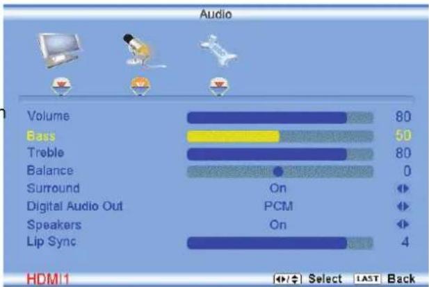
bar
Audio | Category | Value | |---|---| | Volume | 80 | | Bass | 50 | | Treble | 80 | | Balance | 0 | | Surround | On | | Digital Audio Out | PCM | | Speakers | On | | Lip Sync | 4 | HDM 1 Select LAST Back3.9 HDMI Input Setup
The Setup menu operates in the same way for the HDMI Input as for the TV input in section 3.4. The menu difference is that there is no icon along the top for DTV / TV or Parental Control adjustments.

text_image
Setup Language English Sleep Timer Off Wide Wide Input Naming H/V Position Reset All Setting HDMI Select LAST Back3.10 Video Input Picture Adjustment
The Picture Adjust menu operates in the same way for Video Inputs (Component and AV) as for the DTV / TV input in section 3.2. The menu difference is that there is no icon along the top for DTV / TV adjustments.
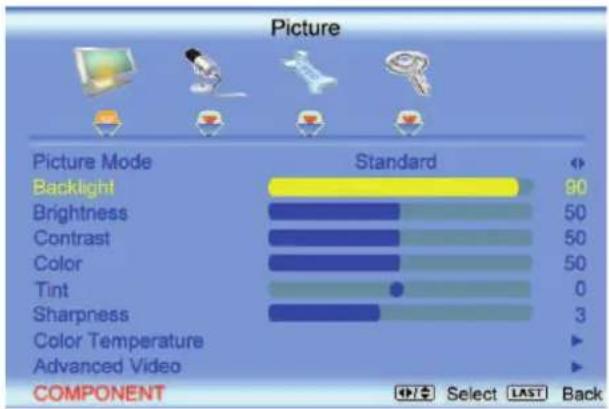
bar
Picture | Picture Mode | Standard | | :--- | :--- | | Backlight | 90 | | Brightness | 50 | | Contrast | 50 | | Color | 50 | | Tint | 0 | | Sharpness | 3 | | Color Temperature | ▼ | | Advanced Video | ▼ | COMPONENT Select LAST Back3.11 Video Input Audio Adjustment
The Audio Adjust menu operates in the same way for Video Inputs (Component and AV) as for the DTV / TV input in section 3.3. The menu difference is that there is no icon along the top for DTV / TV adjustments.

bar
Audio | Component | Value | |---|---| | Volume | 50 | | Bass | 90 | | Treble | 50 | | Balance | 0 | | Surround | On | | Digital Audio Out | PCM | | Speakers | On | | Lip Sync | 2 | COMPONENT Select LAST Back3.12 Video Input Setup
The Setup menu operates in the same way for Video Inputs (Component and AV) as for the TV input in section 3.4. The menu difference is that there is no icon along the top for TV adjustments.
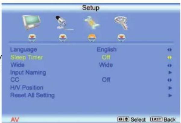
text_image
Setup Language English Sleep Timer Off Wide Wide Input Naming CC Off H/V Position Reset All Setting AV Select LAST Back3.13 Video Input Parental Control
The Parental Control menu operates in the same way for Video Inputs (Component and AV) as for the DTV / TV input in section 3.6. The menu difference is that there is no icon along the top for DTV / TV adjustments.

text_image
Parental Channel Block US TV Rating US Movie Rating Canadian English Rating Canadian French Rating Check for New DTV Rating Block TV Unrated No Access Code Edit COMPONENT MENU Enter Select LAST Back3.14 PC Input Picture Adjustment
The Picture Adjust menu operates in the same way for the PC Input as for the DTV / TV input in section 3.2 for Backlight, Contrast, Brightness and Color Temperature.
3.14.1 Auto Adjust
When the button is pressed, the On Screen Display (OSD) appears on the PICTURE adjustment page.
Press the button to highlight the Auto Adjust selection.
Press the button for the LCD HDTV to adjust to the PC signal timing automatically.
Once the adjustments are completed press the LAST button repeatedly to exit the OSD completely.
3.14.2 Backlight
Press the button to highlight the Backlight selection.
Press the button to start adjusting the brightness of the Backlight and the menu page will disappear and be replaced by a small Backlight Indicator Bar so you can see the light level between the minimum and maximum available levels.

bar
Picture | Method | Value | |---|---| | Auto Adjust | | | Backlight | 90 | | Brightness | 50 | | Contrast | 50 | | Color Temperature | | | H-Size | 60 | | H.Position | 30 | | V.Position | 30 | | Fine Tune | 30 | RGB Select LAST BackUse the ▶ or ▶ button to adjust the level.
Backlight
25
The Backlight level does not affect the Brightness (black level) or Contrast (white level) of the picture, it adjusts the lamp current and this affects the overall brilliance of the picture.
Once the adjustments are completed press the LAST button repeatedly to exit the OSD completely.
3.14.3 Brightness
Press the button to highlight the Brightness selection.
Press the button to start adjusting the brightness and the menu page will disappear and be replaced by a small Brightness Indicator Bar so you can see the brightness level between the minimum and maximum available levels.
Use the < or < button to adjust the level.
Brightness

25
The Brightness adjusts the black levels in the picture. If the brightness is too low you will not be able to see the detail in darker parts of the picture and if the brightness is too high the picture will look washed out.
Once the adjustments are completed press the LAST button repeatedly to exit the OSD completely.
3.14.4 Contrast
Press the button to highlight the Contrast selection.
Press the button to start adjusting the contrast and the menu page will disappear and be replaced by a small Contrast Indicator Bar so you can see the contrast level between the minimum and maximum available levels.
Use the 📄 or button to adjust the level.
Contrast

25
The Contrast adjusts the white levels in the picture. If the contrast is too low the picture will look washed out and if the contrast is too high you will not be able to see any detail in the bright parts of a picture. Once the adjustments are completed press the LAST button repeatedly to exit the OSD completely.
3.14.5 Color Temperature
Press the button to highlight the option for Color Temperature selection.
The default is COOL; this is the 9300K setting.
Press the 📄 or 📄 button if you want to choose the Normal, Warm or Custom option.
Once the adjustments are completed press the LAST button repeatedly to exit the OSD completely.
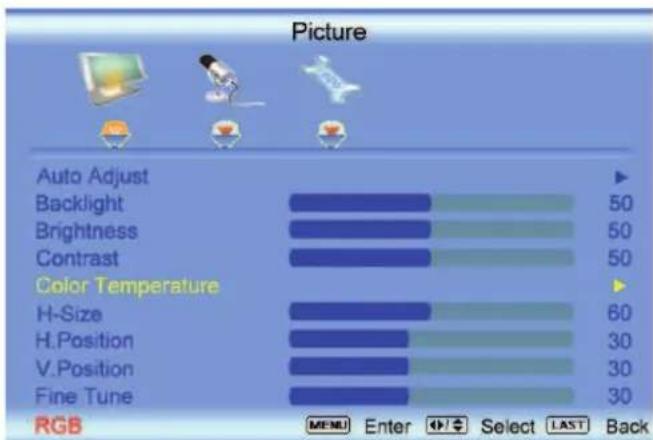
text_image
Picture Auto Adjust Backlight Brightness Contrast Color Temperature H-Size H.Position V.Position Fine Tune RGB MENU Enter Select LAST BackIf you choose the Custom option, then a new menu will be displayed showing the primary color items, Red, Green and Blue. Press the button to highlight the color you wish to adjust.
Press the 📋 button to start adjusting the color and the menu page will disappear and be replaced by a small Color (Red, Green or Blue) Indicator Bar as before. Use the 📋 or 📋 button to adjust the color.
Press the button when finished. Repeat the procedure to adjust the other colors if desired.
Once the adjustments are completed press the LAST button repeatedly to exit the OSD completely.
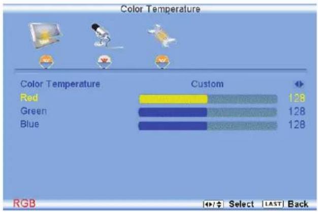
bar
Color Temperature | Color Temperature | Custom | | :--- | :--- | | Red | 128 | | Green | 128 | | Blue | 128 | RGB Select LAST Back3.14.6 H-SIZE
Press the button to highlight the H-Size selection.
Press the button to start adjusting the horizontal size of the picture.
Use the 📄 or 📋 button to adjust the horizontal size.
Once the adjustments are completed press the LAST button repeatedly to exit the OSD completely.
3.14.7 H. Position
Press the button to highlight the Horizontal Shift selection.
Press the button to start adjusting the horizontal position of the picture.
Use the 📄 or 🖱 button to adjust the horizontal position.
Once the adjustments are completed press the LAST button repeatedly to exit the OSD completely.

text_image
Picture Auto Adjust Backlight Brightness Contrast Color Temperature H-Size H.Position V.Position Fine Tune RGB MENU Enter Select LAST Back3.14.8 V. Position
Press the button to highlight the Vertical Shift selection.
Press the 📋 button to start adjusting the vertical position of the picture.
Use the < or button to adjust the vertical position.
Once the adjustments are completed press the LAST button repeatedly to exit the OSD completely.
3.14.9 Fine Tune
Press the 📄 button to highlight the Fine Tune selection.
Press the ☐ button to start tuning the to the PC signal.
Use the
or button to adjust the tuning.
Once the adjustments are completed press the LAST button repeatedly to exit the OSD completely.
3.15 PC Input Audio Adjustment
The Audio Adjust menu operates in the same way for the PC Input as for the DTV / TV input in section 3.3. The menu difference is that there are no icons along the top for DTV / TV and Parental Control adjustments.
3.16 PC Input Setup
The Setup menu operates in the same way for the PC Input as for the DTV / TV input in section 3.4. The menu difference is that there is no icon along the top for TV adjustments and no Closed Caption.

text_image
Setup Language English Sleep Timer Off Wide Wide Input Naming Reset All Setting RGB Select LAST Back3.17 Understanding Viewing Features
Your HDTV features the following viewing modes. You can switch viewing modes using the remote control, please follow the instructions in page 37.
3.17.1 Viewing Modes
Normal Mode
The original 4:3 aspect ratio (1.33:1 source) is preserved, so black bars are added to the left and right of the display image. Standard TV broadcasts are displayed with a 4:3 Aspect Ratio. Movies in 4:3 Aspect Ratio may be referred to as pan-and-scan or full frame. These movies were originally filmed in 16:9 (widescreen), and then modified to fit a traditional TV screen (4:3).
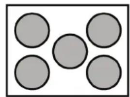
natural_image
Five gray circles arranged in a V-shape within a larger rectangle (no text or symbols)Wide Mode
When watching a standard broadcast or full-frame movie in this mode, the display image is stretched proportionately to fill the TV screen. When watching a widescreen (1.78:1 source) program or movie, the display image fills the TV screen. If you are watching a widescreen (1.85:1 or 2.35:1 source) program or movie, there will still be black bars at the top and bottom.
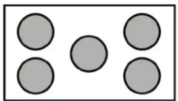
natural_image
Simple diagram of five gray circles arranged in a 2x2 grid within a rectangle (no text or symbols)Panoramic Mode
When watching a standard broadcast or full frame movie in this mode, the 4:3 Aspect Ratio (1.33:1 source) display image is stretched horizontally on the left and right sides to fill the TV screen. The center of the image is not stretched.

natural_image
Five gray circles arranged in a 2x2 grid within a rectangular border (no text or symbols)Chapter 4 Maintenance and Troubleshooting
4.1 Maintenance
Important
- Make sure that the power cable is removed from the socket before cleaning the TV.
- Do not use volatile solvent (such as toluene, rosin and alcohol) to clean the TV. Such chemicals may damage the housing, screen glass and remote control, and cause paint to peel.
Cleaning the Housing and Remote Control
- Use the VIZIO soft cloth (included) for cleaning.
- If the housing or remote control is seriously contaminated, use a soft cloth moistened with diluted neutral cleaner to clean the display. Wring water out of the cloth before cleaning to prevent water from penetrating into the housing. Wipe the display with a dry cloth after cleaning.
Cleaning the Screen
- Use the VIZIO soft cotton cloth (included) to gently clean the screen.
- The screen glass is very fragile. Do not scrape it with any sharp object. Do not press or tap the screen to avoid cracking. When the screen is seriously contaminated, use a soft cloth moistened with diluted neutral cleaner to clean the display. Wring water out of the cloth before cleaning to prevent water from penetrating into the housing. Wipe the display with a dry cloth after cleaning.
4.2 Troubleshooting Guide
If the TV fails or the performance changes dramatically, check the display in accordance with the following instructions. Remember to check the peripherals to pinpoint the source of the failure. If the display still fails to perform as expected, contact the VIZIO for assistance by calling 1-877-MYVIZIO (698-4946) or e-mail us at techsupport@vizio.com.
| Problem Solution | |
| No power. Make sure the power | button is ON (White VIZIO Logo).Make sure AC power cord is securely connected to the AC socket.Plug another electrical device (like a radio) to the power outlet to verify that th outlet is supplying the proper voltage. |
| No sound. Check your audio connection | Press MUTE on the remote control again, so that MUTE disappears from the screenCheck your audio settings, your TV audio may be set to SAP, min or speakers offPress the Volume + (Up) key on your remote controlMake sure that headphones are not connected |
| If the screen is black. | Check your input connections. |
| Power is ON but no screen | Make sure the video cable supplied with the TV is secured to the correct video |
| image. output port on the back | of the VCR and the TV. Make any cable you have attached to the TV is secured to the correct output your Set-Top Box, DVD, etc.Adjust brightness and contrast.Check Source settings. |
| Wrong or abnormal colors appear. | If any colors (red, green, or blue) are missing, check the video cable to make sure it is securely connected. |
| Control buttons do not work. | Press only one button at a time. |
| Remote Control does not work. | Make sure batteries are inserted correctlyBatteries could be weak.Make sure you have selected TV on the remote. |
| There appears to be image quality issues. | For best image quality, view HD wide screen programs where possible. If HD content is not available view “Standard Definition” from a digital source. Standard, analog TV will always be noticeably inferior to HD because your digital flat panel TV has video that is many times better than old TV’s and so you can see interference and deficiencies you did not know you had. |
| You cannot see a picture. Make | sure that the power cord is plugged into a grounded electrical outlet.Make sure that the power button is turned on.Make sure that the selected input source is connected to a working input source.If your TV is connected to your computer in RGB or HDMI mode, press any key on your keyboard to “wake” your computer. |
| You see a distorted picture or hear unusual sound. | You may be getting interference from electrical appliances, cars, motorcycles, or fluorescent lights. If you have not mounted it on the wall, try moving your TV another location to see if this is the cause of the problem. |
| The picture has abnormal patterns. | Make sure that the input source cable is attached securely and correctly to the back of your TV.Make sure that the video input source is within the range of your TV. Compare the video input source’s specifications with your TV specifications. |
| The display image does not cover the entire screen. | If you are using RGB mode, make sure that H Size and V Position in the On Screen Display (OSD) are set correctly.If you are using TV, AV-C (Composite), AV-S (S-Video) or Component with 480i input, follow instructions in page 51 to obtain the desired screen mode. |
| You can see a picture but you cannot hear sound. | Make sure that the volume is not turned down.Make sure that the sound is not muted.Make sure that your audio input source cables are connected securely and correctly. |
| The TV has pixels that are always dark or colored. | Your LCD HDTV is manufactured using an extremely high level of precision technology, however, sometimes some pixels of your LCD HDTV may not display.Pixel defects within industry specifications are inherent to this type of product and do not constitute a defective product. |
| You see “noise” or “trash” on the screen. | When your LCD HDTV’s digital capabilities exceed a digital broadcast signal, the signal is up-converted (increased) to match your TV’s display capabilities. Up-converting can cause noise or trash. |
| You switch to a different input and the volume changes. | The TV remembers the volume level from the last time you adjusted it. If the sound level is higher or lower from another source, then the loudness will change. |
| You switch to a different input and the screen size changes. | The TV remembers the viewing mode from the last time you used a particular input (AV-C (Composite), AV-S (S-Video), Component, HDMI and TV). |
| Tips for High-Definition Users. The | LCD HDTV is an ideal platform for viewing High Definition Content.Best Image Quality will be achieved by the HDMI Input, then YPbPr, then RGB.However, due to variances in broadcast practices, it is possible some image distortions can occur. |
| Tips for Letterbox Content Users. | Letterboxed (or “Widescreen”) versions of DVD movies are most commonly formatted for standard 4:3 Televisions. The LCD HDTV has the capability of expanding this content so the entire screen is filled at the expense of image accuracy. Follow the instructions in page 32. |
4.3 Telephone & Technical Support
Products are often returned due to a technical problem rather than a defective product that may result in unnecessary shipping charges billed to you. Our trained support personnel can often resolve the problem over the phone. For more information on warranty service or repair, after the warranty period, please contact our Support Department at the number below.
Customer support and quality service are integral parts of VIZIO's commitment to service excellence.
For technical assistance contact our VIZIO Technical Support Department via email or phone.
Email: techsupport@vizio.com
(877) 698-4946 Fax: (949) 585-9563
Hours of operation: Monday - Friday: 6 am to 9 pm
Saturday – Sunday: 8 am to 4 pm
Please have your VIZIO model number, serial number, and date of purchase available before you call.
VIZIO
Address:
39 Tesla
Irvine, CA 92618 USA
Telephone: (949) 428-2525 Fax: 949-585-9514
Web: www.vizio.com
4.4 Compliance
Caution: Always use a power cable that is properly grounded. Please use the AC cords listed below for each area.
USA UL
Canada CSA
Germany VDE
UK BASE/BS
Japan Electric Appliance Control Act
4.5 FCC Class B Radio Interference Statement
NOTE: This equipment has been tested and found to comply with the limits for a Class B digital device, pursuant to Part 15 of the FCC Rules. These limits are designed to provide reasonable protection against harmful interference in a residential installation. This equipment generates, uses and can radiate radio frequency energy, and if not installed and used in accordance with the instructions, may cause harmful interference to radio communications. However, there is no guarantee that interference will not occur in a particular installation. If this equipment does cause harmful interference to radio or television reception, which can be determined by turning the equipment off and on, the user is encouraged to try to correct the interference by one or more of the following measures:
- Reorient or relocate the receiving antenna.
- Increase the separation between the equipment and receiver.
- Connect the equipment into an outlet on a circuit different from that to which the receiver is connected.
- Consult the dealer or an experienced radio/TV technician for help.
Notice:
- The changes or modifications not expressly approved by the party responsible for compliance could void the user's authority to operate the equipment.
- Shielded interface cables and AC power cord, if any, must be used in order to comply with the emission limits.
- The manufacturer is not responsible for any radio or TV interference caused by unauthorized modification to this equipment. It is the responsibilities of the user to correct such interference.
Chapter 5 Miscellaneous Information
5.1 Specifications
| Specifications | ||
| Panel 21.6" Diagonal | 16:9 Aspect Ratio | |
| Resolution 1920 x 1080 pixels | ||
| Pixel (Dot) Pitch 0.248mm (H) x 0.248mm (V) | ||
| Display Compatibility HDTV (720P) | ||
| Signal Compatibility 480i (SDTV), 480P (EDTV), 720P (HDTV), 1080i (HDTV), 1080P (FHDTV) | ||
| Colors 16.7 Million | ||
| Brightness (cd/m2) 300 nits (typical) | ||
| Contrast 5000:1 with DCR | ||
| Response Time 5ms (typical) | ||
| Viewing Angle >170° (horizontal), >160° (vertical) | ||
| Inputs | 1x RF (ATSC/QAM/NTSC)1x Composite Video and stereo audio1x S-Video | 1x Component and stereo audio2x HDMI v1.3 with HDCP (with stereo audio),1 with Stereo Audio RCA1x RGB plus stereo audio |
| Outputs | 1x SPDIF Optical Digital Audio, 1x Headphone | |
| Features | 1080P FHDTV, HDMI v1.3, Dynamic Contrast Ratio technology, Noise reduction, MTS stereo decoder, Digital amplifier, Dolby Digital for ATSC/QAM, Channel skip/add, Video/input naming capability, Closed caption, Parental control/V-Chip 2.0, Programmable Timer, Zoom, Virtual surround sound, VESA mount compatible. ATSC/Clear QAM tuner, NTSC video decoding via RF or composite video, 3:2 or 2:2 reverse pull-down, 3D de-interlace, Progressive video scan via component video/VGA/HDMI, HDTV via HDMI or component video, FHDTV via HDMI or component video, Color temperature adjustments of 5400K/6500K/9300K, Independent Red/Green/Blue adjustments for color temperature fine tuning, Signal Compatibility 480i (SDTV), 480P (EDTV), 720P (HDTV), 1080i (HDTV), 1080P (FHDTV), Computer support at 640x480/800x600/1024x768/1360x768/1920x1080 via VGA/HDMI | |
| Speakers | 2xBuilt-in, 3W Speakers | |
| Panel Life | 50,000 hours to half the original brightness | |
| Power | ||
| Input | IEC Connector for direct power line connection | |
| Voltage Range | 100 ~ 240Vac at 50/60Hz | |
| Power Consumption | 62W (max), <1W standby | |
| Environmental Conditions | ||
| Operating | Temperature: 5°C~35°C, Relative Humidity: 20~80%, Altitude: 0~14,000 ft | |
| Non-Operating | Temperature: -20°C~50°C, Relative Humidity: 10~90%, Altitude: 0~40,000 ft | |
| Dimensions | 20.99"W x 16.94"H x 8.85"D with stand; 20.99"W x 15.65"H x 2.84"D without stand | |
| Net Weight | 11.88 lbs without stand, 12.76 lbs with stand | |
| Gross Weight | 16.5 lbs | |
Certifications CSA, CSA-US, FCC Class B, Bets 7
*Product specifications may change without notice or obligation.
5.2 Glossary - Standard Definitions
Analog TV: Today's TV system using radio frequency waves to transmit and display pictures and sound.
Aspect Ratio (4x3): Traditional TV "aspect ratio", that is, the screen's width as compared to its height. For example, a "32 inch TV screen" would be 25 inches wide and 19 inches tall.
Aspect Ratio (16x9): "Wide screen TV" aspect ratio which is more like a movie screen than a traditional TV. For example, a "32 inch TV screen" would be 28 inches wide and 16 inches tall.
Digital TV (DTV): Television delivered and displayed using radio frequency waves that contain information that is digitally encoded for improved quality and efficiency.
Enhanced Definition TV (EDTV): A better digital television transmission than SDTV with at least 480P, in a 16x9 or 4x3 display and Dolby digital surround sound. 480P is the quality used by most DVD players. EDTV provides 300-400,000 pixels.
HDTV Monitor (sometimes called HDTV Ready): A set that can display HDTV programming if you have a separate HDTV tuner, HD Cable Set-Top Box or HD Satellite Set-Top-Box Receiver.
HDTV Tuner (also decoder, receiver, set-top box): A device capable of receiving and outputting HDTV signals for display. It may be stand-alone or integrated in the set.
High-Definition Television (HDTV): The best quality picture, wide screen (16x9) display with at least 720 progressively scanned lines (720P) or 1080 interlaced lines (1080i) and Dolby digital surround sound. HDTV provides 900,000-2.1 million pixels.
Integrated HDTV: An HDTV that has the digital tuner built into the set. It does not need a separate set-top box to receive over-the-air DTV signals.
Interlace Scan: A way to scan vertical lines onto a TV picture by scanning all the odd lines first, then filling the in the even lines (this happens instantaneously).
Plug-and-Play or Digital Cable Ready: A DTV or other device for digital cable consumers that plugs directly into the cable jack and does not require a separate set-top box. Plug-and-Play TV owners must obtain a CableCARD from their cable company in order to view scrambled programming services.
Progressive Scan: A way to scan vertical lines onto a TV picture by scanning all the lines consecutively (progressively).
Standard Definition TV (SDTV): Basic digital television transmission that may be displayed with fewer than 480 progressively scanned lines (480P) in 16 x 9 or 4 x 3 format. 480 interlaced (480i) is the quality of today's analog TV system.
Source: Buying a Digital Television, CEA, HDTV Guide, 2005
Note: The Federal Communications Commission (FCC), the Consumer Electronics Association (CEA) and the Consumer Electronics Retailers Coalition (CERC) have made a new tip sheet available for digital television (DTV) retailers to reproduce and distribute to consumers on the sales floor. The file may be downloaded online at www.dtv.gov. While you're there, check out the other useful information in the FCC is making available to consumers interested in learning more about the analog to digital transition.
Index
A
Accessories, 6
Adjustments
Selecting the Screen Size, 64, 70
Stepping through TV Channels, 37
Volume, 12, 37, 65
Advanced Video Features
Adaptive Luma, 45
Black Level Extender, 44
CTI (Color Transient Improvement, 44
DNR (Dynamic Noise Reduction, 44
Flesh Tone, 45
White Peak Limiter, 44
C
Connecting for DTV, 18
Connecting your Basic Set Top Box, 22
Component
Connecting your DVD Player, 25
Connecting your HDTV Set-Top Box, 21
Composite (AV)
Connecting your Basic Set-Top Box, 22
Connecting your DVD Player, 26
Controls
Front Panel, 12
Side Panel, 12
D
Disassembling, 9
DTV
Audio Adjustment, 46
Parental Control, 54
Picture Adjustment, 40
Special Features, 51
Tuner Setup, 49
DTV Audio Adjust
Balance, 47
Bass, 46
Simulated Surround Sound, 47
Speakers On/Off, 47
Treble, 47
Volume, 46
DTV Picture Adjust
Advanced Video, 44
Backlight, 41, 60
Brightness, 41, 61
Color, 42
Color Temperature, 43, 61
Contrast, 42, 61
Sharpness, 43
Tint, 42
Version 9/9/2008 71
DTV Special Features
Closed Caption, 53
Language, 51
Reset, 53
Sleep Timer, 51
DTV Tuner Setup
Auto Search, 49
Daylight Saving, 50
Skip Channel, 49
Time Zone, 50
Tuner Mode, 49
DVI
Connecting your DVD Player, 24
Connecting your HDTV Set-Top Box, 20
F
FCC Bulletin for New TV Owners, 4
G
Glossary, 70
H
HDMI
Connecting your DVD Player, 23
Connecting your HDTV Set-Top Box, 19
HDMI Input
Audio Adjustment, 58
Picture Adjustment, 58
Setup, 58
|
Inputs
Antenna, 4
Connectors, 17
Rear Label, 13
Installation
Base removal, 8
Preparation, 6
Stand Base, 7
Wall Mounting, 6, 8, 31
O
OSD
Brightness Adjustment, 69
Color Adjustment, 17
Contrast Adjustment, 69
Outputs
Using 5.1 Surround with a Home Theatre System, 28
P
Parental Control
Block Unrated Programming, 57
Channel Block, 54
Movie Rating, 56
Password change, 57
TV Rating, 55
PC Input
Audio Adjustment, 63
Picture Adjustment, 60
Setup, 63
PC Picture Adjust
Auto Adjust, 60
Fine Tune, 63
Horizontal Position, 62
Horizontal Size, 62
Vertical Position, 62
R
Remote, 15
Batteries, 16
Range, 16
Remote:, 16
RGB
Connecting your PC, 29
S
safety instructions, 2
Screen Size explanation, 64
Stand Base, 7
S-Video
Connecting your DVD Player, 26
Connecting your VCR, 27
Connecting your Video Camera, 27
T
Technical Specifications, 69
Troubleshooting Guide, 65
TV
Audio Adjustment, 46
Parental Control, 54
Picture Adjustment, 40
Special Features, 51
TV Audio Adjust
Balance, 47
Bass, 46
Simulated Surround Sound, 47
Speakers On/Off, 47
Treble, 47
Volume, 46
TV Picture Adjust
Advanced Video, 44
Backlight, 41, 60
Brightness, 41, 61
Color, 42
Color Temperature, 43, 61
Contrast, 42, 61
Sharpness, 43
Tint, 42
TV Special Features
Closed Caption, 53
Language, 51
Reset, 53
Sleep Timer, 51
TV Tuner Setup, 49
Auto Search, 49
Skip Channel, 49
Tuner Mode, 49
V
Video Input
Audio Adjustment, 59
Parental Control, 60
Picture Adjustment, 59
Setup, 59
W
Watching TV
Basic Adjustments, 37
Basic connections, 31
First Startup, 31
Getting your Programs, 36
Program Information, 38
Status Information, 38