ACAC10051 - Inverter APC - Free user manual and instructions
Find the device manual for free ACAC10051 APC in PDF.

User questions about ACAC10051 APC
0 question about this device. Answer the ones you know or ask your own.
Ask a new question about this device
Download the instructions for your Inverter in PDF format for free! Find your manual ACAC10051 - APC and take your electronic device back in hand. On this page are published all the documents necessary for the use of your device. ACAC10051 by APC.
USER MANUAL ACAC10051 APC
ACAC10051-ACAC10052 ATS Accessory Kit for ACRH301/ACHU300 Series
What's in This Document
ACAC10051 (ACHU300, ACHU300-L) 2
Inventory....2
Installation Procedure ....3
ACAC10052 (ACHU302, ACHU302-L) 10
Inventory....10
Installation Procedure 11
ACAC10051 (ACHU300, ACHU300-L)
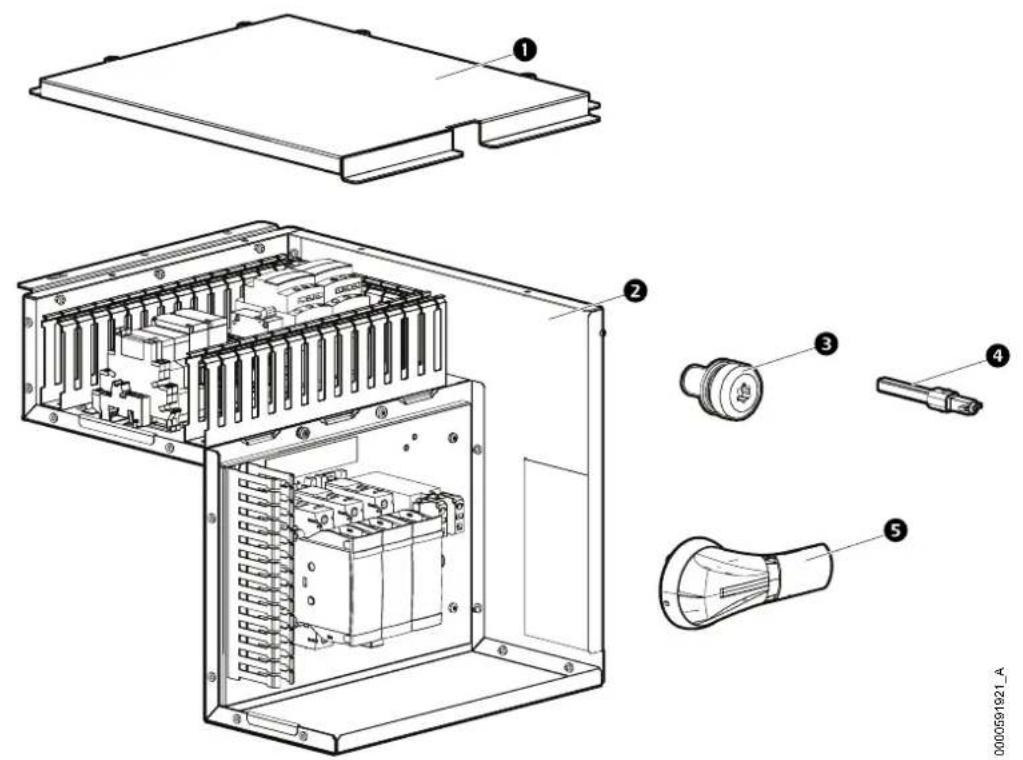
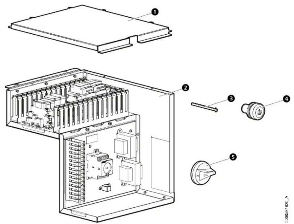
Inventory
text_image
Technical diagram of an electronic device with labeled components including internal circuit, battery pack, and light bulb.Item Description Quantity Item Description Quantity
1
ATS top panel 1 Enclosed switch shaft 1
4
2
ATS BOX Kit (Factory 1 pre-assembled)
5
3
M5x10 TORX screw 3
External switch handle 1
Installation Procedure
⚠️ DANGER
HAZARD OF ELECTRIC SHOCK, EXPLOSION, OR ARC FLASH
- Apply appropriate personal protective equipment (PPE) and follow safe electrical work practices.
- This equipment must be installed and serviced by qualified and trained personnel only.
- Turn off all power supplying this equipment before working on or inside the equipment. For the dry cooler only, it is necessary to remove the power supply plug before opening the electrical panel.
- Replace all devices, doors, and covers before turning on power to this equipment.
Failure to follow these instructions will result in death or serious injury.
- Remove power from the unit.
- Open the electrical panel of the unit.

See the "Panel Removal" section of the unit Installation Manual for instructions on accessing the electrical panel.
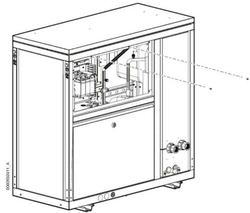
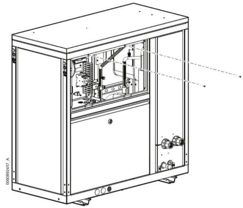
- Remove the two M5x12 Pldrew.
natural_image
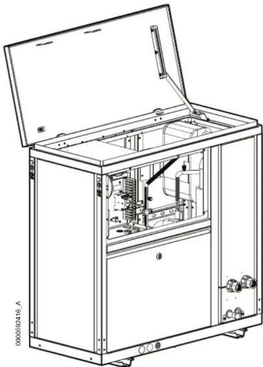
Technical line drawing of an industrial machine cabinet with internal components and mounting base (no text or symbols)- Open the roof panel, then lock the position by the support arm on the right side.

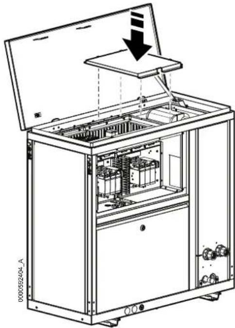
natural_image
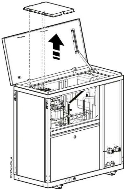
Technical line drawing of an open industrial electrical cabinet with internal components and mounting bracket (no text or symbols)- Remove the electrical box top panel.
natural_image
Technical line drawing of an open industrial machine with internal components and a directional arrow (no text or symbols)- Put the ATS kit in the unit and fix it using three M5xews.TORX

natural_image
Technical line drawing of an open industrial machine with internal components and a downward arrow indicating motion (no text or symbols present)- Connect the cables of the ATS kit to electrical box:
a. Remove the red wire from VFD-1 to MAIN-1 and scrap it.
b. Remove the yellow wire from VFD-3 to MAIN-3 and scrap it.
c. Remove the blue wire from VFD-5 to MAIN-5 and scrap it.
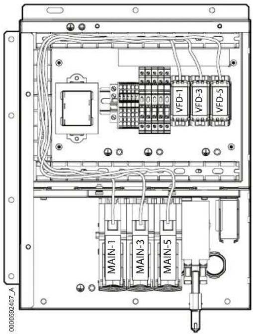
text_image
0000592407_A MAIN-1 MAIN-3 MAIN-5 VFD-1 VFD-3 VFD-5d. Connect the red wire 1 to MAIN-1.
e. Connect the yellow wire 3 to MAIN-3.
f. Connect the blue wire 5 to MAIN-5.
NOTE: The cables are located in the wiring duct.
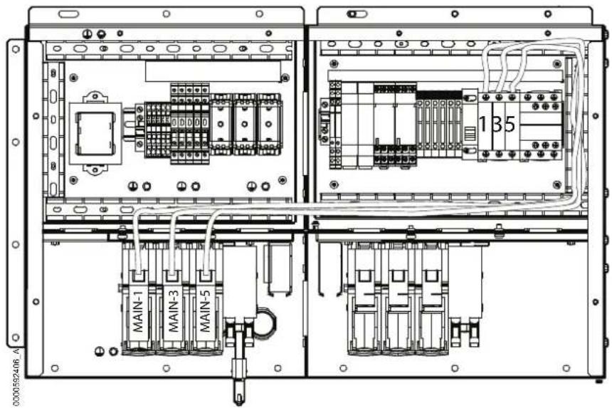
text_image
0000592406 A MAIN-1 MAIN-3 MAIN-5 135g. Connect the red wire 2 to VFD-1.
h. Connect the yellow wire 4 to VFD-3.
i. Connect the blue wire 6 to VFD-5.
NOTE: The cables are located in the wiring duct.
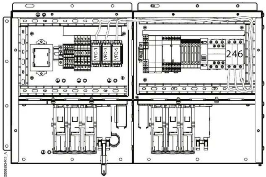
text_image
0000592405_A VFD-1 VFD-3 VFD-5 246- Add ATS top panel and fix the captive screws.
natural_image
Technical line drawing of an open industrial electrical cabinet with internal components and a downward arrow indicating motion (no text or symbols)- Install the electrical box top panel.

natural_image
Technical line drawing of an open industrial machine with internal components and a downward arrow indicating motion (no text or symbols)- Close the panel and fix again the two M5×12reRHIL

natural_image
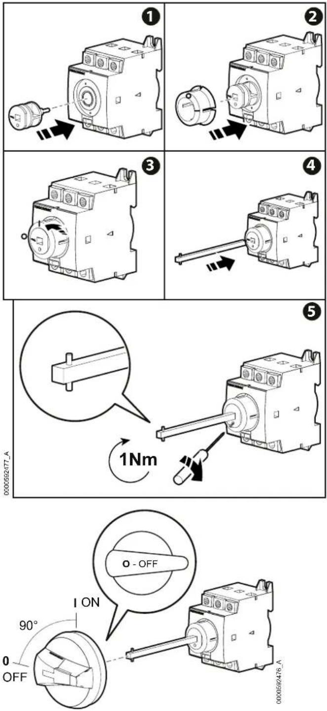
Technical line drawing of an electrical cabinet with internal components and mounting feet (no text or symbols)- Install the enclosed switch shaft as shown in the pictures below.

text_image
0000592421_A ① ② ③ 2.5 3Nm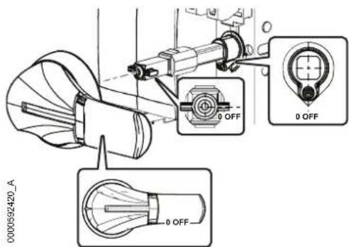
text_image
0000592420_A 0 OFF 0 OFF 0 OFF- Open the bottom front panel.

See the "Panel Removal" section of the unit Installation Manual for instructions on removing.
- Plug in customer cable and connect to the ATS switch.

See the "Electrical Connections" section of the unit Installation Manual for instructions on routing and connecting customer cables.
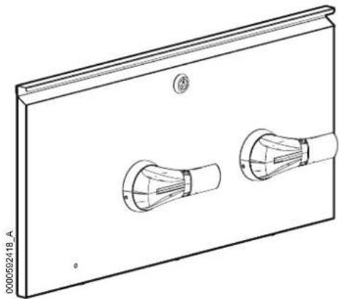
- Remove the octagonal small panel by removing the four M4x8reTQRX then scrap it all.

text_image
0000502419_A- Add the external switch handle in the same location.
natural_image
Technical line drawing of a rectangular panel with two circular components, no text or symbols present- Reinstall the electrical panel.
ACAC10052 (ACHU302, ACHU302-L)
Inventory
text_image
Exploded view diagram of an electronic device showing internal components and labeled partsItem Description Quantity Item Description Quantity
1
ATS top panel 1 Enclosed switch shaft 1
4
2
ATS BOX Kit (Factory 1 pre-assembled)
5
3
M5x10 TORX screw 3
External switch handle 1
Installation Procedure
⚠️ DANGER
HAZARD OF ELECTRIC SHOCK, EXPLOSION, OR ARC FLASH
- Apply appropriate personal protective equipment (PPE) and follow safe electrical work practices.
- This equipment must be installed and serviced by qualified and trained personnel only.
- Turn off all power supplying this equipment before working on or inside the equipment. For the dry cooler only, it is necessary to remove the power supply plug before opening the electrical panel.
- Replace all devices, doors, and covers before turning on power to this equipment.
Failure to follow these instructions will result in death or serious injury.
- Remove power from the unit.
- Open the electrical panel of the unit.

See the "Panel Removal" section of the unit Installation Manual for instructions on accessing the electrical panel.
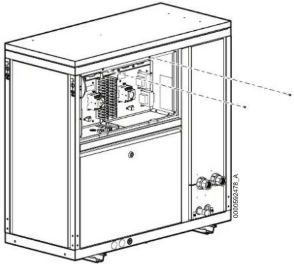
- Remove the two M5x12 Pldrew.
natural_image
Technical line drawing of an industrial electrical cabinet with internal components and mounting feet (no text or symbols)- Open the roof panel, then lock the position by the support arm on the right side.
natural_image
Technical line drawing of an open industrial machine with internal components and mounting base (no text or symbols)- Remove the electrical box top panel.

natural_image
Technical line drawing of an open industrial machine with internal components and a directional arrow (no text or symbols)- Put the ATS kit in the unit and fix it using three M5xews.TORX
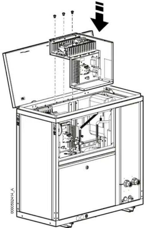
natural_image
Technical line drawing of an open industrial machine with internal components and a downward arrow indicating motion (no text or symbols present)- Connect the cables of the ATS kit to electrical box:
a. Remove the red wire from VFD-1 to MAIN-1 and scrap it.
b. Remove the yellow wire from VFD-3 to MAIN-3 and scrap it.
c. Remove the blue wire from VFD-5 to MAIN-5 and scrap it.
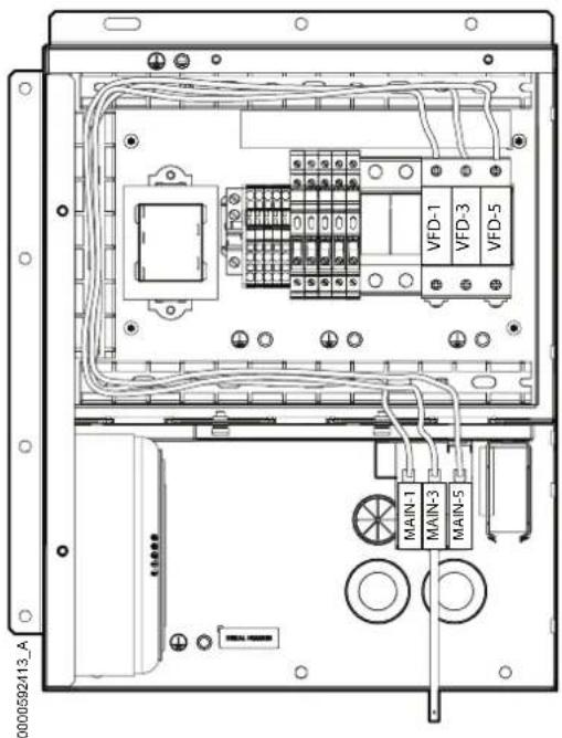
text_image
0000592413_A VFD-1 VFD-3 VFD-5 MAIN-1 MAIN-3 MAIN-5d. Connect the red wire 1 to MAIN-1.
e. Connect the yellow wire 3 to MAIN-3.
f. Connect the blue wire 5 to MAIN-5.
NOTE: The cables are located in the wiring duct.

text_image
0000592412-A MAIN-1 MAIN-3 MAIN-5 1 3 5g. Connect the red wire 2 to VFD-1.
h. Connect the yellow wire 4 to VFD-3.
i. Connect the blue wire 6 to VFD-5.
NOTE: The cables are located in the wiring duct.

text_image
0000592481_A VFD-1 VFD-3 VFD-5 246- Add ATS top panel and fix the captive screws.

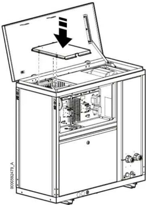
natural_image
Technical line drawing of an open industrial machine with internal components and a downward arrow indicating motion (no text or symbols)- Install the electrical box top panel.
natural_image
Technical line drawing of an open industrial machine with internal components and a downward arrow indicating motion (no text or symbols)- Close the panel and fix again the two M5×12reRHIL
natural_image
Technical line drawing of an industrial machine cabinet with internal components and mounting base (no text or symbols)- Install the enclosed switch shaft as shown in the pictures below.
- Open the bottom front panel.

See the "Panel Removal" section of the unit Installation Manual for instructions on removing.
- Plug in customer cable and connect to the ATS switch.

See the "Electrical Connections" section of the unit Installation Manual for instructions on routing and connecting customer cables.
- Remove the octagonal small panel by removing the four M4x8reTORX then scrap it all.

text_image
0000592475_A- Add the external switch handle in the same location.

natural_image
Technical line drawing of a rectangular panel with two circular switches and a handle (no text or symbols)- Reinstall the electrical panel.