VTC-IRM30-2812 - Security Camera Vitek - Free user manual and instructions
Find the device manual for free VTC-IRM30-2812 Vitek in PDF.

User questions about VTC-IRM30-2812 Vitek
0 question about this device. Answer the ones you know or ask your own.
Ask a new question about this device
Download the instructions for your Security Camera in PDF format for free! Find your manual VTC-IRM30-2812 - Vitek and take your electronic device back in hand. On this page are published all the documents necessary for the use of your device. VTC-IRM30-2812 by Vitek.
USER MANUAL VTC-IRM30-2812 Vitek
natural_image
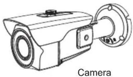
Exterior view of a VITEK security camera with mounted lens and mounting flange (no visible text or symbols beyond brand name)FEATURES:
• 1/2.8" Sony® STARVIS 2.1 MegaPixel CMOS Sensor
- 2.1 MegaPixel with Full 1080p/720p HD/EX-SDI 1.0, 2.0 / TVI / AHD / CVI / CVBS Output
- Advanced Starlight Technology Offers Dramatically Higher Sensitivity to Light Producing Color Images in Very Dark & Night Scenes
- MegaPixel IR Corrected 2.8\~12mm Motorized Varifocal Lens with 1 click focus for easy Configuration
• 30 Dynamic Infrared LEDs at 850nm enable viewing in total darkness up to 100 feet
• Dual Glass Compartments to Eliminate IR Reflection
• 3D-DNR Digital Noise Reduction
• True Day/Night by ICR - Dual Filter Switch
• Fully programmable True WDR (Dual Scan)
• ROI (Region of Interest) WDR achieves superior exposure compensation specifically in exact areas of interest while reducing HDD storage space
- Secondary Video Output & OSD Control Joystick are accessible inside a gasket sealed removable side panel
- Advanced OSD Functions: Motion Detection, Privacy Mask, Defog, Sens-up(\~x32), Sharpness, Mirror/Flip, BLC/HLC, Deblur, Anti-Saturation, Title Set, D-WDR
• 3-Axis mount with Simple One Turn Positioning Lock for Ease of Installation
• IP-67 Rated Water Resistance
• 12VDC / 24VAC Dual Voltage Operation
Safety Precaution
To prevent electric shocks and risk of fire hazards, do NOT use other than specific power source.

text_image
CAUTION RISK OF ELECTRIC SHOCK . DO NOT OPEN CAUTION: TO REDUCE THE RISK OF ELECTRIC SHOCK, DO NOT REMOVE COVER (OR BACK). NO USER SERVICEABLE PARTS INSIDE. REFER SERVICING TO QUALIFIED SERVICE PERSONNEL.
The symbol is intended to alert the user to the presence of uninsulated "dangerous voltage" within the product's enclosure that may be of sufficient magnitude to constitute a risk of electric shock to persons.
The symbol is intended to alert the user to the presence of important operating and maintenance(servicing) instructions in the literature accompanying the unit.
- Warning :
This equipment has been tested and found to comply with the limits for a Class A digital device, pursuant to part 15 of the FCC Rules. These limits are designed to provide reasonable protection against harmful interference when the equipment is operated in a commercial environment. This equipment generates, uses, and can radiate radio frequency energy and, if not installed and used in accordance with the instruction manual, may cause harmful interference to radio communications. Operation of this equipment in a residential area is likely to cause harmful interference in which case the user will be required to correct the interference at his own expense.
- Caution :
Any changes or modifications in construction of this device which are not expressly approved by the party responsible for compliance could void the user's authority to operate the equipment.
Main power quality should be that of a typical commercial environment. If the user of the model requires continued operation during power main interruption, it is recommended that the model be powered from an uninterruptible power supply (UPS).
Safety Precaution

NOTICE
- The image used in this instruction manual are processed to help comprehension and may differ from actual video of the camera.
- Avoid installing in areas where shock or vibrations may occur.
- Pay attention to safety when running the connection cable and observe that the cable is not subjected to heavy loads, kinks or damage and no moisture can get in.
• The warranty becomes void if repairs are undertaken by unauthorized persons. - Maintenance and repair have to be carried out only by authorized service centers.
• Use only a mild detergent to clean the housing. - The camera should never be operated beyond the technical specifications. This can lead to damage and void the warranty.
• The camera should never be operated in water.
Contents
p.02\~03 Safety Precaution
p.04 Contents
p.05 Composition
p.05 Dimensions
p.06\~09 Installation Instructions
p.10\~26 Operating Instructions
p.27 Specifications
Composition
natural_image
Line drawing of a surveillance camera with mounting flange (no text or symbols)
Operating Instruction

Mounting Template
Plastic Anchor: 6 x 30mm (3pcs)
Mounting Screw: 4 x 40mm (3pcs)
Torque Wrench: 3mm (1pc)
Video Sub-out: Cable (1pc)


Dimensions

text_image
3.17" 3.73" 3.43"
text_image
9.72" 9.29" 3.64"Part Names
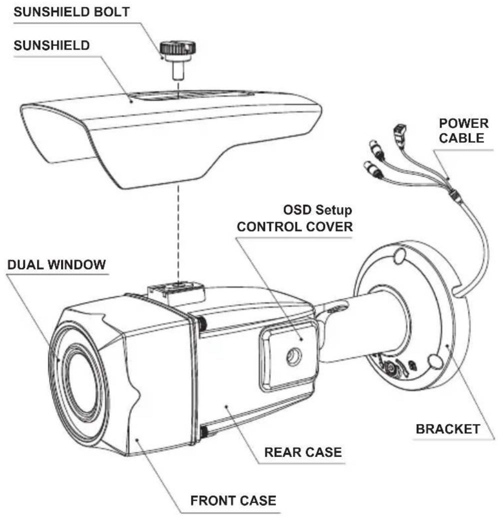
text_image
SUNSHIELD BOLT SUNSHIELD DUAL WINDOW OSD Setup CONTROL COVER FRONT CASE REAR CASE BRACKET POWER CABLE
CAUTION
• Extreme care should be taken NOT to scratch the window in front of lens.
- Care should be taken that the cable is not damaged, kinked or exposed in hazardous areas.
- Do not expose the camera directly to a strong light source such as the sun or spotlight.
Installation Instructions
- Locate the mounting template at the installation position and drill the ceiling or wall if needed.
- Route the Power cable to the connecting place.
- Place the camera bracket on pre-drilled position and attach it using mounting screws (4x40mm).
- Set the camera's viewing angle by using the L-wrench.
- Put the sunshield onto the camera unit and tighten the sunshield-bolt.
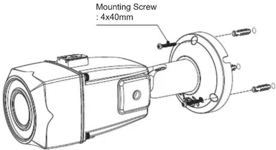
text_image
Mounting Screw : 4x40mm■ Adjustment of viewing angle with one-touch 3-Axis bracket
text_image
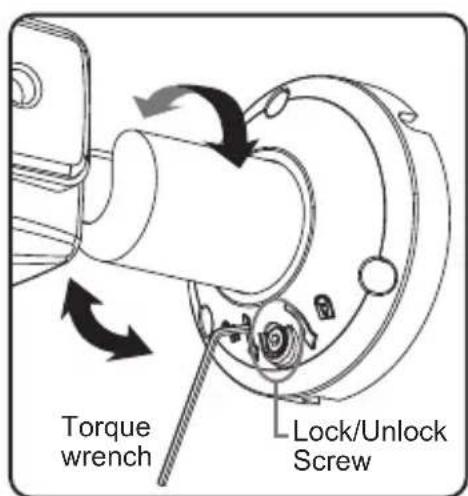
Torque wrench Lock/Unlock ScrewInstallation Instructions
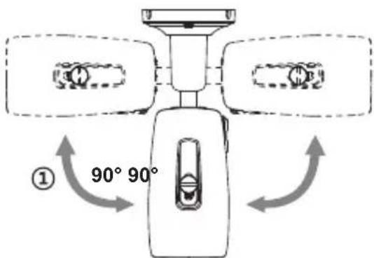
Pan & Tilt adjustments
- Unlock the screw on the camera bracket through using the torque wrench supplied
- Set the camera's viewing angle then lock the screw on the bracket.
1) Pan limit:
Pan is limited to +/- 90°.
2) Tilt limit:
Tilt is limited to 0^(2^) min 90^ max. for wall(ceiling) installation respectively with reference to the wall(ceiling) when the inclination of camera module is 0^ , that is, the image is aligned horizontally.
text_image
① 90° 90°
text_image
② 90° • on the wall • on the ceiling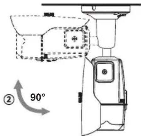
text_image
② 90°3) Inclination limit
(Horizontal image alignment): Inclination limited to +/-90° max.

text_image
③ ±90°Installation Instructions
Installation Instructions
• Make sure power is removed before the installation.
- Follow the order for applying power:
Connect the power leads to the camera (observe polarity for DC power) then plug-in power. This will avoid damage to the camera from power surges and improper resetting.
Power Supply Connections
Camera can work with either 12VDC or 24VAC, dual voltage power. Primary and secondary grounds are completely isolated to avoid the possible ground-loop problems.

text_image
SDI OUTPUT (Yellow) ANALOG OUTPUT (Black) POWER (AC24V/DC12V)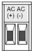
- AC(+): AC24V/DC12V
- AC(-) : AC24V/GND
※ Please use the cable as provided with camera. If camera cable is cut and re-wired, the transmission distance of video can be reduced. Especially SDI cable should not be cut because it requires detailed wiring and affects the transmission distance.
Operating Instructions
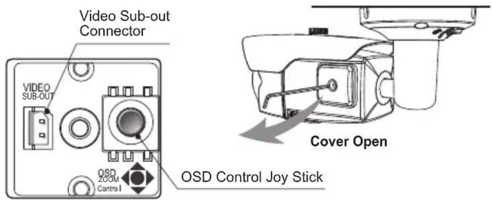
Using OSD Controller
Setup menu can be accessed and controlled by OSD control joystick on the side of the camera. Five commands are available with the joy stick. The design of OSD could be different according to the Model.
text_image
Video Sub-out Connector VIDEO SUB-OUT OSD ZOOM Control OSD Control Joy Stick Cover Open
Description of the OSD control operation
1] SET Key (●): Access to the menu or enter the setting. To enter the main menu, press the Set Key down.
2] UP/DOWN Key (▲/▼): Choose the desired sub-menu and to move the cursor up or down.
3] LEFT/RIGHT Key (◄/►): Set up the value of the selected menu. Used to adjust the desired menu selection and to move the cursor left or right.

Description of the Motorized ZOOM&FOCUS\* adjustment
(*) Works only when OSD Menu is inactive.
1) ▲ : Zoom In
3) ◀: Focus Near
2) ▼ : Zoom Out
4) ▶ : Focus Far
※ ANALOG OUT should be set to TVI MODE, AHD MODE or CVI MODE to get CVBS video in sub-out. If it is set to CVBS, there is no CVBS video in sub-out port. (SYSTEM> OUTPUT> ANALOG OUTPUT0)
※ If CVBS video is enabled through ANALOG OUT or Sub-out port, WDR and 3D-NR functions are disabled in all video outputs.
It should be considered when installer adjusts the video with installation monitor via CVBS video signal.
Operating Instructions
OSD menu Table
| MENU SUB | MENU CONFIGURATION | ||||
| LENS | DC | MODE (INDOOOR, OUTDOOR, DEBLUR) | |||
| MANUAL | |||||
| ZOOM / FOCUS | AF MODE | ZOOMPUSH, MANUAL | |||
| MODE CHANGE | ENABLED, DISABLED | ||||
| SCANNING | HALF, FULL | ||||
| ONEPUSHAF | ON | ||||
| SYNC TDN | ON, OFF | ||||
| INITIAL ON | |||||
| EXPOSURE | BRIGHTNESS | 0~20 | |||
| SHUTTER | AUTO | ||||
| MANUAL(SPEED) | 1/30(1/25), 1/60(1/50), 1/120(100), 1/250(200),1/500(400), 1/1000(800), 1/2000(1600), 1/4000(3200), 1/8000(6400), 1/15000(12800), 1/30000(25600) | ||||
| FLICKERLESS | |||||
| SENS-UP | OFF, x2, x4, x8, x16, x32 | ||||
| AGC | 0~10 | ||||
| BACKLIGHT | OFF | ||||
| HLC LEVEL, COLOR | |||||
| BLC | H/V-POS, H/V-SIZE | ||||
| WDR | MODE ROI WIN | DOW ZONE/USE, | |||
| H/V-POS, H/V-SIZE | |||||
| NORMAL | |||||
| TARGET-BRT | LOW, MIDDLE, HIGH | ||||
| WEIGHT | LOW, MIDDLE, HIGH | ||||
| DAY & NIGHT | EXTERN | SMART IR, ANTI-SAT., DELAY, IR LED CTL (AUTO, OFF) | |||
| AUTO | SMART IR, ANTI-SAT., AGC THRES, AGC MARGIN, DELAY | ||||
| COLOR | |||||
| B&W | SMART IR, ANTI-SAT. | ||||
| COLOR | AWB | AUTO, AUTOext, PRESET, MANUAL (C-TEMP, R/B-GAIN) | |||
| COLOR GAIN | 0~20 | ||||
| 3D-NR | OFF, LOW, MIDDLE, HIGH | ||||
| IMAGE | SHARPNESS | MAINOUTPUT | ANALOGOUT0 | ANALOGOUT0 | TVI MODE, AHD MODE,CVBS, CVI MODE |
| TVI MODE 0~10 | |||||
Operating Instructions
| IMAGE | SHARPNESS MA | N OUTPUT | ANALOG OUT0 | AHD MODE 0~10 | ||
| CVI MODE 0~10 | ||||||
| ANALOG OUT1 | ANALOG OUT1 | CVBS | ||||
| SDI&CVBS | 0~10 | |||||
| SDI OUTPUT | SDI OUT HD- | -SDI, EX-SDI 1.0, EX-SDI 2.0, OFF | ||||
| SDI&CVBS | 0~10 | |||||
| GAMMA | 0.45, 0.55, 0.65, 0.75 | |||||
| OFF, ONMIRROR | ||||||
| FLIP | OFF, ON | |||||
| D-WDR | OFF, LOW, MIDDLE, HIGH | |||||
| DEFOG | OFF, ON | MODE (AUTO, MANUAL) | ||||
| LEVEL (LOW, MIDDLE, HIGH) | ||||||
| PRIVACY ZONE | NOMEZONE DISP, | H/V-POS, H/V-SIZE, Y LEVEL, CB/CR LEVEL, TRANS | ||||
| MOTION | OFF, ON | DET WINDOW | WINDOW ZONE, WINDOW USE, DET H/V-POS, DET H/V-SIZE | |||
| DET TONE | 0~4 | |||||
| MDRECT FILL | OFF, ON | |||||
| SENSITIVITY | 0~10 | |||||
| MOTION OSD | OFF, ON | |||||
| TEXT ALARM | OFF, ON | |||||
| SYSTEM | OUTPUT | SDI OUTPUT | HD-SDI, EX-SDI 1.0, EX-SDI 2.0, OFF | |||
| ANALOG OUT0 | TVI MODE, AHD MODE, CVBS, CVI MODE | |||||
| RESOLUTION | 1080 30P(25P), 720 30P(25P), 720 60P(50P) | |||||
| TV SYSTEM | US(NTSC), EU(PAL) | |||||
| LANGUAGE | ENG, CHN(S), CHN, JPN, KOR, GER | |||||
| CAM TITLE | OFF, RIGHT UP, LEFT DOWN | |||||
| RESET | ON | |||||
| EXIT | SAVE, CANCEL | |||||
Operating Instructions
OSD menu Startup
Press the 'OSD menu SET key' down to access the setup menu mode.
- EXIT : Enters 'EXIT' menu with save current setting or without save.
- RETURN : Returns to the previous menu.
MENU V0. XX
| 1. LENS | DC |
| 2. ZOOM/FOCUS | |
| 3. EXPOSURE | |
| 4. BACKLIGHT | OFF |
| 5. DAY&NIGHT | EXTERNAL |
| 6. COLOR | |
| 7. 3D-NR | MIDDLE |
| 8. IMAGE | |
| 9. MOTION | OFF |
| A. SYSTEM | |
| B. EXIT | SAVE |
1. LENS
Lens can be selected either DC or MANUAL lens.
It should be selected according to lens type.
1-1. DC DC is for the best image when DC Auto iris lens is installed
- MODE : Selects MODE according to lighting condition.
- INDOOR: Optimized for indoor environment.
- OUTDOOR: Optimized for outdoor environment.
- DEBLUR: If enabled it will reduce motion blur in certain indoor environments but can cause more noise and color rolling.
1-2. MANUAL MANUAL is for the best image when a Fixed lens is installed.
2. ZOOM/FOCUS
2-1. AF MODE
- ZOOMPUSH: Focusing works steadily for sharp focusing on the object. In the case of a Motor driven lens, focusing resumes in about 7\~8 seconds to save the lens lifetime when the focus gets lost.
- MANUAL: Focusing can only be adjusted by ▲, ▼ of OSD control joystick.
Operating Instructions
2. ZOOM/FOCUS
| AF MODE | ZOOMPUSH |
| MODE CHANGE | DISABLED |
| SCANNING | HALF |
| ONEPUSHAF | ON |
| SYNC TDN | OFF |
| INITIAL | ON |
| RETURN |
AF MODE Changes to MANUAL automatically after 3 hrs when MODE CHANGE is ENABLED.
2. ZOOM/FOCUS
| AF MODE | MANUAL |
| MODE CHANGE | NOT USED |
| SCANNING | HALF |
| ONEPUSHAF | ON |
| SYNC TDN | OFF |
| INITIAL | ON |
| RETURN |
2-2. MODE CHANGE (Available only with AF MODE is ZOOMPUSH)
MODE CHANGE is activated to set ZOOMPUSH in AF MODE. It is for locking of the lens control to prevent undesirable operation.
- ENABLED : Locks and disables the lens operation after 3 hours.
It is recommended to maintain the working-life of the motorized zoom lens. - DISABLED : Disables the locking feature allowing lens operation at any time.
2-3. SCANNING
Lens scanning can be set to performs HALF or FULL on the screen.
Scanning checks the positions for zoom/focus at both of the end positions and saves them for reference.
2-4. ONEPUSHAF
Focusing is activated only when zoom in/out is working.
2-5. SYNC TDN
Compensates for IR correction when the camera switches to DAY or NIGHT. It is recommended to set OFF except specific conditions.
2-6. INITIAL
Lens initialization is necessary during the installation or the regular operation to align the position data with the mechanical positions whose lens elements may move and deviate from its calibrated position by shock or vibration, for example, during transportation. Lens initialization is automatically executed at power up.
INITIAL starts the lens initialization when pressing the joystick straight down for about 2 sec. It is strongly recommended to execute LENS INIT in cases below;
- At the final step of installation.
- When focus becomes out of control by shock or vibration.
3. EXPOSURE
3. EXPOSURE
| BRIGHTNESS | 9 |
| SHUTTER | AUTO |
| SENS-UP | X2 |
| AGC | 7 |
| RETURN |
3-1. BRIGHTNESS
Adjusts the brightness of video (0\~20).
3-2. SHUTTER
Select AUTO or MANUAL.
If shutter is set to Manual mode, SENS-UP mode is deactivated.
3-2-1. AUTO: Optimizes the video level by controlling the iris and the shutter speed automatically.
3-2-2. MANUAL : 1/30(1/25), 1/60(1/50), 1/120(100), 1/250(200), 1/500(400), 1/1000(800), 1/2000(1600), 1/4000(3200), 1/8000(6400), 1/15000(12800), 1/30000(25600) Shutter can be set to fixed.
3-2-3. FLICKERLESS : Flicker is used to remove the flickering on screen due to differences in light and electric frequencies.
3-3. SENS-UP
A brighter video can be obtained by increasing the exposure time at night with SENS-UP. It can be set to Off, x2, x4, x8, x16 or x32.
A higher setting will have a brighter video but more noise will be in the image.
3-4. AGC
AGC(0\~10) amplifies the video gain for brighter video but noise may occur.
Operating Instructions
4. BACKLIGHT
Compensates the video image by cutting out the bright areas with a mask or adjusting the contrast of the video.

text_image
HLC LEVEL 10 COLOR BLK RETURN ↻4-1. HLC (High Light Compensation)
Cuts out the bright area with a mask and excludes it from compensation.
4-1-1. LEVEL (0\~20): Sets the HLC level. It determines the video level that starts cutting out. Lower setting starts the cut out at a lower light level. The cut out area is masked with selected color.
4-1-2. COLOR : Select mask color from 9 colors. Black, White, Yellow, Cyan, Green, Magenta, Red, Blue and Customize.

text_image
BLC H-POS 8 V-POS 7 H-SIZE 3 V-SIZE 3 RETURN ↙4-2. BLC (Backlight Compensation)
This function is used to brighten an image in the foreground with a bright light area behind it such as sunlight, limiting the affect of silhouette. BLC has a target window for compensation and its size and position can be set by H-POS, V-POS, H-SIZE and V-SIZE.
4-2-1. H-POS, V-POS :
Sets the position of BLC area to move vertically and horizontally.
4-2-2. H-SIZE, V-SIZE :
Sets the size of BLC area to move vertically and horizontally.
Operating Instructions

flowchart
graph LR
    A["WDR"] --> B["ROI"]
    A --> C["MODE ROI"]
    A --> D["TARGET-BRT MIDDLE"]
    A --> E["WEIGHT MIDDLE"]
    A --> F["RETURN ↓"]
    G["ROI"] --> H["WINDOW ZONE 0"]
    G --> I["WINDOW USE ON"]
    G --> J["H-POS 469"]
    G --> K["V-POS 194"]
    G --> L["H-SIZE 739"]
    G --> M["V-SIZE 688"]
    G --> N["RETURN ↓"]
4-3. WDR (Wide Dynamic Range)
When part of an image is extremely dark but another part is so bright you can't see any details WDR will even the image out.
4-3-1. MODE : Selects WDR mode normal or ROI setting.
• NORMAL: WDR function applies full screen.
- ROI (Region Of Interest) : Sets specific area of WDR by window setting. Select window zone number from 0 to 3 and window use set to on. Then the window zone can be modified for position and size.
4-3-2. TARGET-BRT : LOW, MIDDLE, HIGH
Selects the brightness value of the target area in MODE.
4-3-3. WEIGHT : LOW, MIDDLE, HIGH
Selects the WDR value of the target area in MODE.
※ If CVBS video is enabled through ANALOG OUT or Sub-out port, WDR and 3D-NR functions are disabled in all video outputs. It should be considered when installer adjusts the video with installation monitor via CVBS video signal.
Operating Instructions
5. DAY & NIGHT
DAY/NIGHT is used to control the setting during day-time and night-time operation. Select the mode according to the light condition and the camera types.
MENU V0. XX
| 1. LENS | DC |
| 2. ZOOM/FOCUS | |
| 3. EXPOSURE | |
| 4. BACKLIGHT | OFF |
| 5. DAY&NIGHT | EXTERN |
| 6. COLOR | |
| 7. 3D-NR | MIDDLE |
| 8. IMAGE | |
| 9. MOTION | OFF |
| A. SYSTEM | |
| B. EXIT | SAVE |
- DAY&NIGHT
| SMART IR | ON |
| ANTI-SAT. | 10 |
| DELAY | MIDDLE |
| IR LED CTL | AUTO |
| RETURN |
5-1. EXTERN
DAY or NIGHT is determined by the built-in light photo sensor for cameras with built-in IR LEDS..
5-1-1. SMART IR
: SMART IR can be set to reduce the saturation of strong IR illumination at night in any menu of EXTERN, AUTO and B/W(NIGHT). Set to ON, SMART IR is enabled and ANTI-SAT. level is controlled.
5-1-2. ANTI-SAT. (Available only with the SMART IR is ON)
: Sets the anti saturation level 0\~20. Setting high level avoids the saturation but the corners will be darker accordingly.
5-1-3. DELAY
: D→N DELAY is time in seconds while camera maintains its status before Day to Night switching. DELAY can avoid the unwanted/frivolous switching by short term lights such as light from a passing car. Set delay term to low, middle or high.
5-1-4. IR LED CTL
: IR LED Control(AUTO/OFF) is available with IR LED model only. If it is set to OFF, IR LED will be turned OFF but DAY or NIGHT is still determined by the built-in light photo sensor.
Operating Instructions
5-2. AUTO
Used when DAY or NIGHT is determined by light level through the lens and DAY from/to NIGHT is switched automatically by the scene brightness. It can be controlled by the AGC threshold level, AGC margin and delay time.
5. DAY&NIGHT
SMART IR
ANTI-SAT.
AGC THRES
AGC MARGIN
DELAY
RETURN
ON
10
10
10
MIDDLE

5-2-1. SMART IR
: SMART IR can be set to reduce the saturation of strong IR illumination at night in any menu of EXT, AUTO and B/W(NIGHT). Set to ON, SMART IR is enabled and ANTI-SAT. level is controlled.
5-2-2. ANTI-SAT. (Available only with the SMART IR is ON)
: Sets the anti saturation level 0\~20. Setting high level of ANTI-SAT can make the corners darker
5-2-3. AGC THRES
: AGC(Auto Gain Control) is a threshold level which determines to switch DAY from/to NIGHT in AUTO mode. Higher value makes the camera switch DAY from/to NIGHT at brighter illumination.
5-2-4. AGC MARGIN
: Sets the gap level switching from/to DAY(color) or NIGHT(B/W).
5-2-5. DELAY
: D→N DELAY is time in seconds while camera maintains its status before Day to Night switching. DELAY can avoid the unwanted/frivolous switching by a short term light such as light from a passing car. Set delay term low, middle or high.
5-3. COLOR
The camera is always in COLOR mode.
DAY/NIGHT is disabled and outputs color video.
5-4. B/W
The camera is always in B/W mode.
Forcibly removes IR cut filter and switches to B/W regardless of light level.
Operating Instructions
6. COLOR
- COLOR
AWB
COLOR GAIN RETURN
AUTO
10

6-1. AWB (Auto White Balance)
Automatically tracks the changes of color temperature and continuously adjusts the white balance. AUTO, AUTOext, PRESET and MANUAL modes are available.
6-1-1. AUTO : Optimized for Indoor installation and compensates AWB for low color temperature such as incandescent lights.
6-1-2. AUTOext: Optimized for outdoor sunlight applications and compensates AWB for high color temperature such as sunlight.
6-1-3. PRESET : AWB is performed only whenever ● is pressed.
6-1-4. MANUAL : White balance is fixed to the settings by Color-Temperature Red-GAIN and Blue-GAIN. It can be used only when the color temperature does not vary.
6-2. COLOR GAIN
Sets the color gain control level 0\~20.
Operating Instructions
7. 3D-NR (Digital Noise Reduction)
DNR function improves picture quality by filtering out signal noise which is generated under low light conditions. Set off, low, middle or high level. 3DNR(3-dimensional noise reduction) which reduces noise by multi frames. It is effective in low light. Set to high will reduce the most noise but the image will be less sharp and a tailing effect might occur.
MENU V0. XX
| 1. LENS | DC |
| 2. ZOOM/FOCUS | |
| 3. EXPOSURE | |
| 4. BACKLIGHT | OFF |
| 5. DAY&NIGHT | EXTERN |
| 6. COLOR | |
| 7. 3D-NR | MIDDLE |
| 8. IMAGE | |
| 9. MOTION | OFF |
| A. SYSTEM | |
| B. EXIT | SAVE |
※ If CVBS video is enabled through ANALOG OUT or Sub-out port, WDR and 3D-NR functions are disabled in all video outputs. It should be considered when installer adjusts the video with installation monitor via CVBS video signal.
8. IMAGE
- IMAGE
| SHARPNESS | |
| GAMMA | 0.55 |
| MIRROR | OFF |
| FLIP | OFF |
| D-WDR | OFF |
| DEFOG | OFF |
| PRIVACY | OFF |
| RETURN | |
SHARPNESS
| MAIN OUTPUT | ANALOG OUTO |
| ANALOG OUTO | TVI MODE↓ |
| SDI&CVBS | 5 |
| CVI MODE | 5 |
| TVI MODE | 6 |
| AHD MODE | 7 |
| RETURN |
Operating Instructions
8-1. SHARPNESS
Sets the Sharpness level 0\~10. Increases or decreases the sharpness of the picture. Too much sharpness can make image harsh and show more noise as well as line flicker at the edge of object in the picture.
8-2. GAMMA
Adjust gamma level of video.
8-3. MIRROR
The Video is reversed left and right if turned ON.
8-4. FLIP
The Video is reversed upside down if turned ON. When the video is flipped Vertical, then the joystick directions are reversed accordingly. It is very useful when a camera is installed upside down.
8-5. D-WDR
Improves the visibility for the bright areas and the dark areas by compensating the video gain. Care should be taken to select low, middle or high level, because video may lose its quality in some environments by over compensation. Video noise can be increased in the dark area accordingly.
8-6. DEFOG
Enhance foggy video according to status of scene. Video quality can be less in normal environments. Sets AUTO or MANUAL mode.
8-6-1. MODE :
- AUTO : Enhance foggy video automatically according to status of scene.
- MANUAL : Set to enhance foggy video manually regardless of status of scene.
8-6-2. LEVEL : Set Low, Mid or High.
Video quality can be less in normal environments.
8-7. PRIVACY
Set ON/OFF for enabling/disabling PRIVACY mask. 16 privacy areas are available and each area is programmable in size, color, position and transparency.
8-7-1. ZONE NUM : Selects mask zone number from 0 to 15 to be adjusted.
8-7-2. ZONE DISP: Displays OFF/ON for the mask area which you selected.
8-7-3. H-POS, V-POS :
Adjusts the mask area H, V position which you selected.
Operating Instructions
PRIVACY
| ZONE NUM | 0 |
| ZONE DISP | ON |
| II-POS | 12 |
| V-POS | 2 |
| H-SIZE | 3 |
| V-SIZE | 3 |
| Y-LEVEL | 10 |
| CB LEVEL | 10 |
| CR LEVEL | 10 |
| TRANS | 0 |
| RETURN |
8-7-4. H-SIZE, V-SIZE :
Adjusts the mask size using H, V direction.
8-7-5. Y LEVEL : Adjusts the mask color by Y LEVEL. (0: black \~ 20: white)
8-7-6. CB LEVEL : Adjusts the mask color by CB LEVEL. (0: yellow \~20: blue)
8-7-7. CR LEVEL : Adjusts the mask color by CR LEVEL. (0: Green \~20: magenta)
8-7-8. TRANS.: Selects transparency rate for the mask area from 0 to 3
0 : Privacy mask is not transparent.
1 : Privacy mask is 25% transparent.
2 : Privacy mask is 50% transparent.
3 : Privacy mask is 100% transparent.
9. MOTION
4 motion detection areas are available and each area is programmable in size and location. Motion can be detected in the area and displays the results in blocks and/or a text message.
9-1. DET WINDOW : Sets the MOTION DETECTION areas on screen.
9-1-1. WINDOW ZONE : Set the detection zone number from 0 to 3.
9-1-2. WINDOW USE : Sets ON/OFF motion detection area which you selected. If set to ON, It can be adjusted position and size.
9-1-3. DET H-POS, V-POS : Adjusts the detection area H, V position.
9-1-4. DET H-SIZE, V-SIZE : Adjusts the area size using H, V direction.
Operating Instructions
9. MOTION
| DET WINDOW | J |
| DET TONE | 2 |
| MDRECT FILL | ON |
| SENSITIVITY | 5 |
| MOTION OSD | OFF |
| TEXT ALARM | OFF |
| RETURN | J |
DET WINDOW
| WINDOW ZONE | 0 |
| WINDOW USE | ON |
| DET H-POS | 1 |
| DET V-POS | 1 |
| DET H-SIZE | 58 |
| DET V-SIZE | 32 |
| RETURN | ↓ |
9-2. DET ZONE
Sets the detection zone 0 to 4 display types which window use setting ON.
0 : Set 100% opacity level of video background except detection window zone.
1 : Set 50% opacity level of video background except detection window zone.
2 : Set 25% opacity level of video background except detection window zone.
3 : Video background image is same as detection window zone.
4 : Detection window zone is displayed with box line
9-3. MDRECT FILL
Sets the motion display type when motion is detected in video.
Setting ON will display a red solid box type.
Setting OFF will display a red outline box type.
9-4. SENSITIVITY
Sets the detection sensitivity for motion (0\~10). Higher values increase the sensitivity to detect motion. Too low of a value will cause the erratic detection by tree leaves or light level changes.
9-5. MOTION OSD
Set ON or OFF to display motion results.
9-6. TEXT ALARM
Setting ON enables to display a text message ' WINDOWS MOVING!!' or icon when motion is detected.
Operating Instructions
A. SYSTEM
Sets the system related functions.
A. SYSTEM
OUTPUT
RESOLUTION
TV SYSTEM
LANGUAGE
CAM TITLE
RESET
RETURN

1080 30P
US(NTSC)
ENG
OFF


OUTPUT
SDI OUTPUT
ANALOG OUTO
RETURN
HD-SDI
TVI MODE

HD-ANALOG
MAIN OUTPUT
ANALOG OUTO
Y GAIN
CB GAIN
CR GAIN
POSITION
BURST FREQ
BURST GAIN
B&W
UTC TYPE
720 EX
RETURN
ANALOG OUTO
TVI MODE
16
65
68
128
128
108
BURST ON
Pelco-C
OFF

A-1. OUTPUT : Selects the main video output.
A-1-1. SDI OUTPUT :
Selects the SDI output HD-SDI, EX-SDI 1.0, EX-SDI 2.0, OFF
A-1-2. ANALOG OUT0 :
Selects HD-ANALOG modes TVI MODE, AHD MODE, CVI MODE or CVBS.
It can be controlled Y-Gain, CB/CR-Gain, Position, Burst and etc.
Set ANALOG OUT to AHD MODE, TVI MODE or CVI MODE if CVBS
video is necessary through sub-out port.
If ANALOG OUT is set to CVBS, there is no CVBS video through sub-out port.
Operating Instructions
※ If CVBS video is enabled through ANALOG OUT or Sub-out port, WDR and 3D-NR functions are disabled in all video outputs. It should be considered when installer adjusts the video with installation monitor via CVBS video signal.
A-2. RESOLUTION
Select the video resolutions, 1080P/720P are available. 1080P outputs 1920x1080 video at the frame rate of 30P/25P. 720P outputs 1280x720 video at the frame rate of 60P/50P.
A-3. TV SYSTEM
Selects HDTV standards for analog video, output switches to 60HZ, US(NTSC) or 50HZ, EU(PAL) accordingly.
A-4. LANGUAGE
6 languages are available for OSD menu. English, Korean, Japanese, Chinese(S), Chinese, German.
A-5. CAM TITLE
Camera title(name) can be set and edited with alphanumeric characters. Select the camera title position 'LEFT DOWN' or 'RIGHT UP' on the video. Then ◀,▶ moves the cursor and ▲,▼ choose a character to select it. The selected characters are added and displayed on the input line.
CAM TITLE

U, D - CHAR SELECT L, R - POSITION ENTER - RETURN
A-6. RESET : Resets camera to factory default.
B. EXIT : Exits SETUP MENU and returns to the normal display.
B-1. SAVE : Save all the settings and exit the setup menu.
B-2. CANCEL : Exit the setup menu without saving.
Detailed Specifications
| Imaging Sensor | 1/2.8" Sony® STARVIS 2.1 MegaPixel CMOS Sensor |
| Effective Pixels | 1920(H) x 1080(V) x 30p |
| Scan Frequency | 30Hz(V), 22.5Khz(H) / Progressive |
| Video Format | HD: 16:9, 1080p@30fps / CVBS: 16:9 (NTSC) |
| Video Output | HD/EX-SDI 1.0, 2.0 / TVI / AHD / CVI / CVBS |
| Video Resolution | 2.1 MegaPixel 1080p (1920x1080) |
| Min.Illumination | Color: 0.08 Lux (LED Off), B/W: 0.005 Lux (LED Off) |
| S/N Ratio | More than 50dB (AGC Off) |
| Lens | MegaPixel 2.8~12mm @ F1.4 Motorized Varifocal |
| Exposure | Brightness / Shutter / Sens-up / AGC |
| Dynamic Intensity IR LEDs | Built-in 30pcs x 850nm IR-LEDs |
| IR Range | 100' |
| DAY / NIGHT | TDN by Dual Filter Switch, EXTERN / AUTO / COLOR / B&W |
| White Balance | AUTO / AUTOext / PRESET / MANUAL |
| WDR | True Dual Scan WDR |
| ROI (Region of Interest) WDR | Yes |
| DNR | 3D-NR |
| MIRROR/FLIP | Off / On |
| Functions | Motion Detection, Privacy Mask, Defog, Sens-up(~x32), Sharpness, Mirror/Flip, BLC/HLC, Deblur, Anti-Saturation, Title Set, D-WDR |
| Remote Control | CoC (Control over COAX) via DVR HD-TVI / AHD |
| Operating Power | 12VDC / 24VAC (Dual Voltage) |
| Weather Resistance | IP67 |
| Operating Temp. | -4° ~ 122°F (-20° ~ +50°C) @ 20-80% RH |
| Weight | 31.75oz (900g) |
| Dimension (WxHxD) | 3.17" x 3.43" x 9.72" (80.5 x 87 x 247mm) |

text_image
OnCue BridgeCONSIDER THESE OTHER
GREAT PRODUCTS FROM

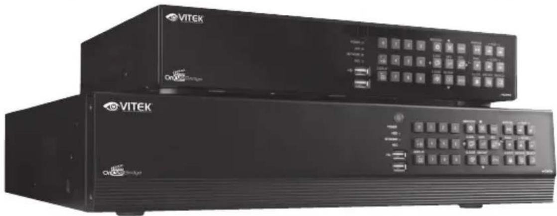
natural_image
Two black VITEK-branded electronic devices with control panels and keyboard (no visible text or symbols)OnCue Bridge
8 & 16 Channel Complete HD/EX-SDI, TVI, AHD, CVI, Analog & IP Recording Solution
8 & 16 Channel Stand-alone Real-time Video Recorders
• Supports IP, HD/EX-SDI, TVI, AHD, CVI, Analog (CVBS) Cameras with automatic format detection
• Full HD MegaPixel Real-time recording, live display, and playback
• Panorama (Thumbnail) Search
• HDMI 2.0 (4K), VGA, and BNC Outputs
- Plug and Play & Auto configuration for IP Cameras via OnVIF or generic protocol
- Point-Of-Sale (POS) Integration
- Alarm In/Out
• 2-way Full Duplex Audio
• Video Analytics with Search Feature (Camera Dependent)
- Remote Viewing via CMS Software, Internet Explorer, and Mobile Phones (iOS/Android)
• Web-based remote configuration
- Advanced Video Detection: Camera tampering, Camera lens blocking, Day&Night, Defocus
• Supports up to 30TB Internal Storage (VT-HDOC16BR) / 12TB Internal Storage (VT-HDOC8BR)
• eSATA for storage extension of up to 5 more HDD
- Configurable Advanced Mirroring (Dual Recording, RAID1)
• RS-485 / CoC (Control Over Coax) PTZ Control
LIMITED PRODUCT WARRANTY
VITEK products carry a three (3) year limited warranty. Digital recording and storage products are also warranted for 3 years. * Per a special agreement with Western Digital, as of August 2016, VITEK also warrants factory installed Hard Drives for the full 3 year span of the recorder warranty provided that the recorder was purchased through an authorized VITEK distributor.
VITEK warrants to the purchaser that products manufactured by VITEK are free of any rightful claim of infringement or the like, and when used in the manner intended, will be free of defects in materials and workmanship for a period of three (3) years, or as otherwise stated above, from the date of purchase by the end user. This warranty is non-transferable and extends only to the original buyer or end user customer of a Vitek Authorized Reseller.
This warranty shall not apply to repairs or replacements necessitated by any cause beyond the control of VITEK, including but not limited to, acts of nature, improper installation, excess moisture, misuse, lack of proper maintenance, accident, voltage fluctuations, or any unauthorized tampering, repairs or modifications. This warranty becomes VOID in the event of alteration, defacement, or removal of serial numbers.
Within the first 6 months of purchase, VITEK will replace or credit any defective product returned at the request of the customer (subject to availability) with a new product that equals or exceeds the performance of the original product purchased.
Within the first 6 months of purchase, at its sole discretion, VITEK may issue an advance replacement for a defective product; however, all related costs including, but not limited to shipping and/or delivery charges will be the responsibility of the customer. If upon return inspection a product is determined to be in good working order or shows evidence of misuse, the customer will be responsible for full payment of the original product purchased as well as the replacement product.
Beyond the first 6 month period for the remainder of the warranty, VITEK'S responsibility shall be limited to repairing the defective product, including all necessary parts and related labor costs. At its sole discretion, VITEK may choose to either exchange a defective product or issue a merchandise credit towards future product purchases. Any replacement parts furnished in connection with this warranty shall be warranted for a period not to exceed the remaining balance of the original equipment warranty.
A Return Authorization number or “RA” number must be obtained prior to the return of any item for repair, replacement, or credit. VITEK requires that this “RA” number be clearly printed on the outside of the shipping carton to avoid refusal of said shipment. The Return Authorization number expires after 30 days. Products returned after the 30 day period will be subject to refusal. Shipping charges, if any, must be prepaid. A copy of the bill of sale (or invoice of purchase), together with a complete written explanation of the problem must accompany all returns.
Vitek makes no warranty or guarantee whatsoever with respect to products sold or purchased through unauthorized sales channels. Warranty support is available only if product is purchased through a Vitek Authorized Reseller.
*Limited Warranty means that VITEK reserves the right to repair or replace any product found defective within the warranty time period, prorated to the date of original purchase. If VITEK cannot repair the product, VITEK reserves the right to replace it with an equal or better product and grade at VITEK's discretion.