LS-C1260HE - Washing machine LG - Free user manual and instructions
Find the device manual for free LS-C1260HE LG in PDF.

User questions about LS-C1260HE LG
0 question about this device. Answer the ones you know or ask your own.
Ask a new question about this device
Download the instructions for your Washing machine in PDF format for free! Find your manual LS-C1260HE - LG and take your electronic device back in hand. On this page are published all the documents necessary for the use of your device. LS-C1260HE by LG.
USER MANUAL LS-C1260HE LG
Split System Room Air Conditioner
Safety Instructions
Operating Instructions

Care and Cleaning
Problem Solver

BE01
Models:
Outdoor units Indoor units
AG0AC11BKO AG1AC11BKM
AG0AC13BKO AG1AC13BKM
60Hz, 220Volts
Models:
Outdoor units Indoor units
AG0AC07BWO AG1AC07BWF/G/I
AG0AC09BWO AG1AC09BWF/G/I
AG0AC12BWO AG1AC12BWF/G/I
50Hz, 220-240Volts
Models:
Outdoor units Indoor units
AG0AH07BWO AG1AH07BWF/G/I
AG0AH09BWO AG1AH09BWF/G/I
AG0AH12BWO AG1AH12BWF/G/I
50Hz, 220-240Volts
- Please read this manual carefully and thoroughly before operating this unit.
- Contact the authorized service technician for repair or maintenance of this unit.
- Contact the installer for installation of this unit.
- The appliance is not intended for use by young children or infirm persons without supervision.
- Young children should be supervised to ensure that they do not play with the appliance.
Prior to installation, this air-conditioning unit must be submitted for approval by the utility service which provides electricity (EN 60555-3 Norm).
SAFETY PRECAUTIONS......3
Installation precautions....3
Operation precautions ....4
PRODUCT COMPONENT IDENTIFICATION 7
(1) Feature 7
(2) Indoor Unit, Outdoor Unit 8
(3) Name and Function-Remote Controller 9
(4) Remote Controller Preparation 10
AIR CONDITIONER OPERATION 11
(1) Operation Mode 11
(2) Operation Procedure 11
(3) Sleep Mode Auto-Control Setting 17
(4) Airflow Direction Procedure 18
(5) Setting the Present Time 19
(6) Timer Setting 20
(7) Operation Details 22
FORCED OPERATION 23
CARE AND MAINTENANCE 24
OPERATION TIPS 26
BEFORE CALLING FOR SERVICE 27
natural_image
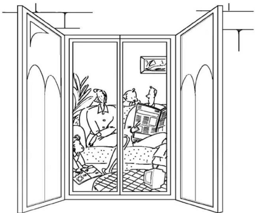
Line drawing of a person reading a newspaper inside a double-framed window (no text or symbols)Before operating, please read the following "Safety precautions" carefully.
To prevent injury to the user or other people and properties damage, the following instructions must be followed.
■ Incorrect operation due to ignoring of instruction will cause harm or damage, the seriousness is classified by the following indications.

Warning
: This indication shows the possibility of causing death or serious injury.
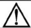
Caution
: This indication shows the possibility of causing injury or damage to properties only.
■ The items to be followed are classified by the following symbols.

Symbol(with white background) denotes item that is PROHIBITED from doing.


Symbol(with white background) denotes item that is COMPULSORY to be carried out.
Installation precautions

WARNING
■ Do not install, remove and reinstall the unit by yourself.
Improper installation will cause water leakage, electrical shock or fire. Please consult authorized dealer or specialist for the installation work.

CAUTION
Please confirm the following important points when installation.
■ This room air conditioner must be earthed.

It may cause electrical shock if grounding is not perfect.
■ Do not install the unit at place where leakage of flammable gas may occur and/or in an explosive atmosphere.

In case of gas leaks and accumulates at the surrounding of the unit, it may cause fire ignition.
■ Confirm drainage piping is connected properly.

If it is not connected perfectly, it may cause water leakage and dampen the furniture.
■ The reverse cycle system of the air conditioner is based on the air cooling type heat pump which absorbs heated air from the outdoor unit and discharges it indoor.
Therefore if the outdoor unit is exposed in the very low temperature, specifically below 0^ C, the heating capacity drops off rapidly. In this case, we recommend customers not to operate the air conditioner.
The temperature described on the labels is measured based on an international standard I.S.O.
| INDOOR | OUTDOOR | ||
| D.B | D.B | W.B | |
| TEMP. | 20±1°C | 7±1°C | 6±1°C |
Operation precautions

WARNING
Plug in the power plug properly.
- Otherwise, it will cause electrical shock or fire due to heat generation or electrical shock.
Do not operate or stop the unit by inserting or pulling out the power plug.
- It will cause electrical shock or fire due to heat generation.
Do not damage or use an unspecified power cord.
- It will cause electrical shock or fire.
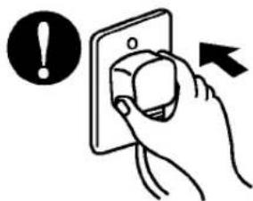
text_image
Diagram showing a hand holding an electrical socket with an exclamation mark and an arrow indicating action or warning.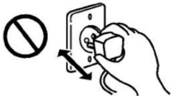
text_image
Diagram showing a hand using an electrical switch to switch against a prohibition symbol, with arrows indicating the process.
text_image
Safety warning illustration showing a tool emitting a power plug with a prohibition symbol and a close-up of the plug.Do not modify power cord length or to share the single outlet with other appliances.
- It will cause electrical shock or fire due to heat generation.
Do not operate with wet hand.
• It may cause electrical shock.
Do not insert your finger or stick, etc. into the air inlet/air outlet.
- Since the fan rotates at high speed, this may cause an injury.

natural_image
Simple line drawing of a plug with a prohibition symbol (no text or labels)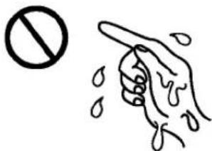
text_image
No dips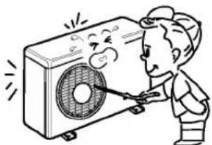
natural_image
Cartoon illustration of a person using a fan to clean air (no text or symbols)Do not expose the skin to cool air directly for long time.
• This could damage your health.
When an abnormality (smell of burning, etc) occurs, stop the air conditioner, and disconnect the power plug or turn off the breaker.
- If the unit continues to be operated in an abnormal condition, it may cause a fire, trouble, etc. In this case, consult your dealer.
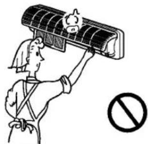
Repair or relocation should not be done by the customer.
• If this is done in correctly, it may cause a fire, electric shock, injury by dropping of the unit, water leakage, etc. Consult your dealer.

text_image
Illustration showing a person reacting to a high-pressure air conditioner with a prohibition symbol below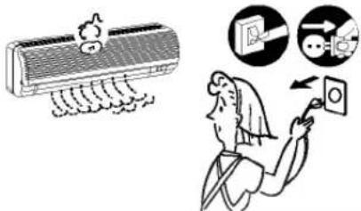
text_image
Illustration showing a car air conditioner and a person using a touchscreen with icons for cleaning and interaction.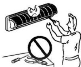
text_image
Illustration showing a person using a device with a warning symbol and a crossed-out circle, indicating a hazard or incorrect use.
CAUTION
When the air filter is to be removed, do not touch the metalparts of the indoor unit.
• It may cause an injury.
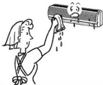
Do not clean the air conditioner with water.
• Water may enter the unit and degrade the insulation. It may cause an electric shock.
Ventilate well when used together with a stove, etc.
natural_image
Illustration of a person using a solar panel to clean air, with no text or symbols presentWhen the unit is to be cleaned, switch off, and turn off the breaker.
natural_image
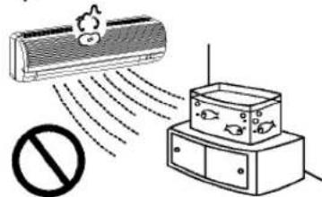
Cartoon illustration of a person cleaning an air conditioner with a smiling face (no text or symbols)Do not put a pet or house plant where will be exposed to direct air flow.

natural_image
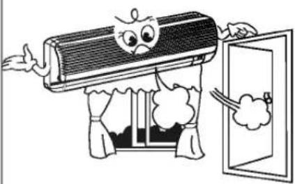
Illustration of a person reaching toward a window with cloud, next to a smiling face and an exclamation mark (no text or symbols)Do not use for special purposes.
- Since the fan rotates at high speed during operation, it may cause an injury.
• This could injure the pet or plant.
- Do not use this air conditioner to preserve precision devices, food, animal, plants and art objects. It may cause deterioration of quality, etc.

text_image
Illustration showing a person using an air conditioner to clean a wall-mounted air conditioner, with warning symbol and electrical outlet nearby.Do not operate switches with wet hands.

text_image
Illustration showing a potted plant emitting exhaust from a wall-mounted air conditioner, with a prohibition sign nearby.Do not apply an insecticide or flammable spray.
text_image
Diagram showing airflow of a high-voltage air conditioner emitting exhaust, with a prohibition symbol below.Do not put a stove, etc. where is exposed to direct air flow.
• It may cause an electric shock.
- It may cause a fire or deformation of the cabinet.
• It may cause imperfect combustion.

natural_image
Illustration of a person cleaning an air conditioner with raindrops, showing hand and cloth (no text or symbols)
text_image
Cartoon illustration showing a distressed air conditioner emitting smoke, with a prohibition symbol nearby.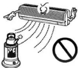
text_image
Illustration showing a spray gun emitting exhaust from a refrigerated air drain, with a prohibition sign nearby.
CAUTION
- It may cause an injury.

natural_image
Illustration of two people holding briefcases with a smiling air conditioner and an exclamation mark (no text or symbols)• In the cooling mode, if it is operated in a room with high humidity (80% r.h. or more) for a long time, water condensed in the air conditioner may drop and may wet and spoil furniture, etc.
- It may cause an injury through dropping or falling down.
- It may case an injury, etc. by falling down.
natural_image
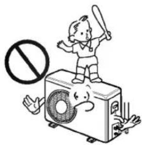
Illustration of a child standing on a high-voltage air conditioner unit with a prohibition symbol (no text or labels)
natural_image
Illustration of a person using a large air conditioner on a table with a 'no' symbol nearby (no text or labels)• The unit may drop or fall down and cause an injury.

natural_image
Cartoon illustration of a smiling air conditioner on a bench with a prohibition sign (no text or symbols)For installation

WARNING
- Consult your dealer for installing the air conditioner.

CAUTION
- Do not connect a grounding wire to a gas pipe, water pipe, lightning rod or ground wire of a telephone. If a grounding is incorrect, it may cause an electric shock.

Install an earth leakage breaker depending on the place where the air conditioner is to be installed (humid place, etc
• If the earth leakage breaker is not installed, it may cause an electric shock

- If gas leaks and collect around the unit, it may cause an explosion.
- If the drainage route is incomplete, water may drop from the unit. It may wet and spoil furniture.

A Soft Dry Operation Mode(page 13)
This mode is designed to dehumidify without overcooling.
/B Auto Operation(page 14)
In selecting this mode of operation, the setting temperature, indoor fan speed, and the desired operation mode are automatically set by Fuzzy rule on the basis of sensing the room temperature.
During Auto Operation, the vertical louver swings up and down automatically in according to 1/f rhythm. Pressing the Airflow Direction Control Button will set the louvers as the desired position. If you want to go on with the 1/f swing of vertical the louver, press again the Airflow Direction Control Button.
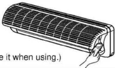
natural_image
Line drawing of a wall-mounted air conditioner with a remote control unit attached (no text or symbols)Wireless Remote Controller puts all functions at your fingertips.
CON/OFF Dual Timer Setting(page 21)
You can program the room air conditioner to turn itself on or off so as to ensure you maximum comfort when you return from being away.
-DSleep Mode Auto Control(page 17)
A touch of the Sleep Mode Button automatically controls the indoor fan speed, and adjusts the setting temperature to create a more comfortable sleep.
CAUTION
of handling the Remote Controller
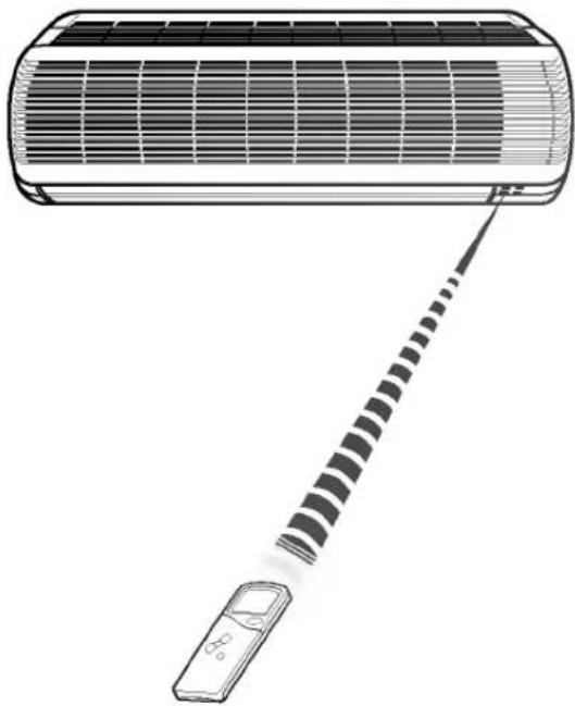
- Aim at the signal receptor on the room air conditioner so as to operate.
- The remote control signal can be received at a distance of up to about 7m.
- Be sure that there are no obstructions between the remote controller and the signal receptor.
- Do not drop or throw the remote controller. Do not place the remote controller in a location exposed to direct sunlight, or near the heating unit, or any other heat source.
- Block a strong light over the signal receptor with a curtain or etc. so as to prevent the abnormal operation. (ex:electronic quick start, ELBA, inverter type fluorescent lamp)
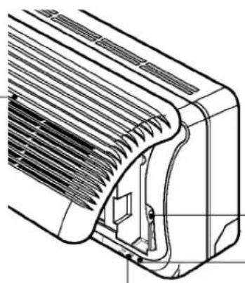
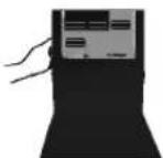
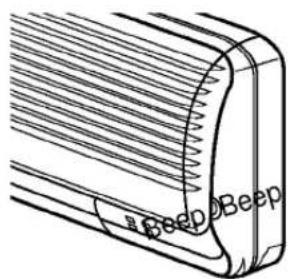
Indoor Unit

text_image
Air Intake Vent (front panel) Air Outlet Vent Horizontal Airflow Direction Louver Vertical Airflow Direction Louver (The air outlet vent opens when the operation starts.) Power supply Cord Remote Controller Storage (11K, 12K, 14K) Panel Opening Air Filters (behind front panel)Indoor unit controls and indicators
Open the front panel
Pull the both ends of front panel and hang upward like below picture.
natural_image
Technical line drawing of a mechanical component with internal structure and mounting bracket (no text or symbols)Forced Operation Button
Used for operation when the remote controller cannot be used.
Signal Receptor
Receives the signals from the remote controller.
(Signal receiving sound:two short beeps or one long beep.)
Operation Indication Lamps
① On : Lights up during the air conditioner operation.
Sleep Mode : Lights up during Sleep Mode Auto operation.
Timer : Lights up during timer operation.
* Deice Mode : Lights up during Defrosting. (Heat pump model)
OUT : Lights up during the compress DOOR operation. (Cooling model)
Outdoor Unit
Air Intake Vents
Air Outlet Vent
(Side)
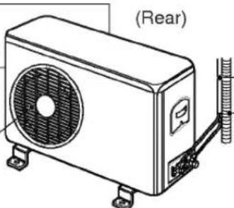
text_image
(Rear)Piping
Drain Hose
Heat pump model: Room Air Conditioner for cooling and heating
Cooling model: Room Air Conditioner for cooling
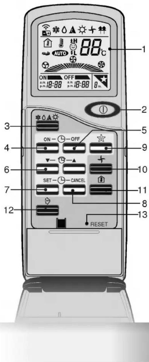
Remote Controller
Signal transmitter
Transmits the signals to the room air conditioner.
text_image
1 ON OFF a.m. 18:08 a.m. 18:08 8 h. 2 3 4 5 6 7 8 9 10 SET CANCEL 11 12 RESETA Operation display
Displays the operation conditions.
/B Start/Stop Button
Operation starts when this button is pressed, and stops when the button is pressed again.
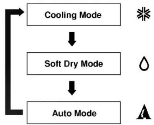
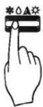
C Operation Mode Selection Button
Used to select the operation mode.
• Cooling Operation Mode.
- Soft Dry Operation Mode.
• Auto Operation Mode.
• Heating Operation Mode. (Heat Pump Only).
DON Timer Button
Used to set the time of starting operation.
OFF Timer Button
Used to set the time of stopping operation.
/F Time Setting Button
Used to adjust the time.
√G Timer Set Button
Used to set the timer when the desired time is obtained.
H Timer CANCEL Button
Used to cancel the timer operation.
I Sleep Mode Auto Button
Used to set Sleep Mode Auto Operation.
/J FAN Operation Button
Used to circulate room air without cooling or heating.
K Room Temperature Checking Button
Used to check the room temperature.
√L Airflow Direction Control Button
Used to set the desired airflow direction.
/M Reset Button
How to store the remote controller
(11K, 12K, 14K Models)
1 Pull the both ends of front panel slightly to open.

natural_image
Diagram of a heat exchanger or cooling unit with cooling fins and cooling ends (no text or symbols)2 Hang the front panel upward and keep the remote controller.
text_image
e it when using.)(Remove it when using.)
3 Press the left and the right side to close the front panel.

natural_image
Diagram of a heat exchanger or air duct system with cooling fins and airflow arrows (no text or labels)How to mount onto a wall
(All Models)
1 Use the screws to secure the holder to the wall.

natural_image
Hand using a screwdriver to adjust or install a mechanical component (no text or symbols visible)Confirm that the remote control signals can reach the signal receptor of unit.
2 To attach the remote controller to the holder.
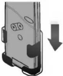
natural_image
Diagram of a smartphone rear panel with a downward arrow indicating compression or disassembly (no text or symbols present)3 To remove.
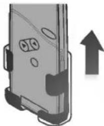
natural_image
Illustration of a smartphone rear panel with an upward arrow indicating growth (no text or symbols)How to insert batteries
1 Remove the battery cover from the remote controller.
- Slide the cover according to the arrow direction.
Insert the two batteries.
- Be sure that the (+) and (-) directions are correct.
- Be sure that both batteries are new.
Re-attach the cover.
- Slide it back into position.


- Do not use rechargeable batteries, such batteries differ from standard dry cells in shape, dimensions, and performance.
- Remove the batteries from the remote controller if the air conditioner is not going to be used for some long time.
AIR CONDITIONER OPERATION
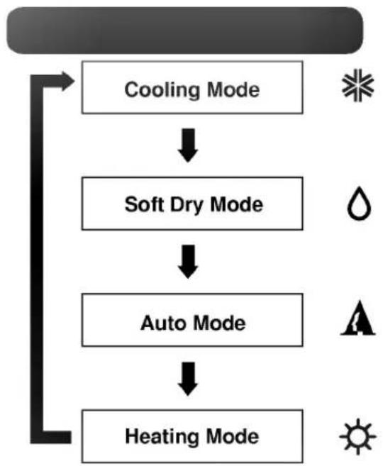
flowchart
graph TD
    A["Cooling Mode"] --> B["Soft Dry Mode"]
    B --> C["Auto Mode"]
    C --> D["Heating Mode"]
(Heat Pump Model)
flowchart
graph TD
    A["Auto Mode"] --> B["Soft Dry Mode"]
    B --> C["Cooling Mode"]
(Cooling Model)

text_image
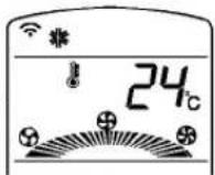
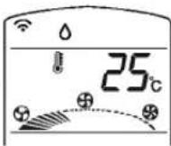
1st Start/Stop Button 2nd Operation Mode Selection Button 3rd Room Temperature Setting Button 4th Indoor Fan Speed Selection ButtonA Cooling Operation Mode
(① LED lamp ON)
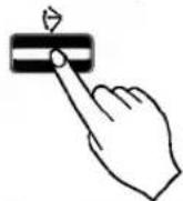
1 Press the Start/Stop Button.


text_image
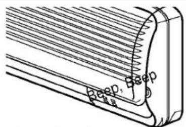
Beep Beep- Two short beeps will sound and the operation lamp will light up.
2 Select Cooling Operation.
Press the Operation Mode Selection Button.
Each time the button is pressed, the operation mode is shifted in the arrow direction.
Operation Display
Cooling Operation

Soft Dry Operation


Auto Operation

Heating Operation (Heat pump model only)
3 Set the temperature lower than the room temperature.
text_image
24°C- The temperature can be set within a range of 18^ 30^ by 1^ .

text_image
To raise the Temperature To lower the Temperature4 Set the fan speed.


text_image
24°C- Select the fan speed in four steps -low, medium, high, Auto.
• The display shows high fan speed.
• Each time the button is pressed, the fan speed mode is shifted.
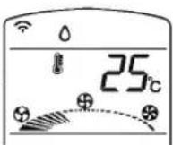
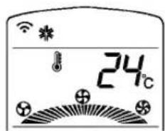
/B Soft Dry Operation Mode
This mode dehumidifies without overcooling.
(① LED lamp ON)
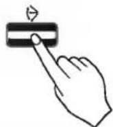
1 Press the Start/Stop Button.
natural_image
Technical line drawing of a mechanical component with parallel grooves and a base (no text or symbols)- Two short beeps will sound and the operation lamp will light up.
2 Select Soft Dry Operation.
Press the operation Mode Selection Button.
Each time the button is pressed, the operation mode is shifted in the arrow direction.

flowchart
graph LR
    A["Operation Display"] --> B["Cooling Operation"]
    B --> C["Soft Dry Operation"]
    C --> D["Auto Operation"]
    D --> E["Heating Operation\n(Heat pump model only)"]
3 Set the Temperature lower than the room temperature.
- The temperature can be set within a range of 18°C\~30°C by 1°C.

text_image
To raise the Temperature To lower the Temperature4 During Dry Operation
- The indoor fan speed is automatically set to the low, so the shift of the indoor fan speed is impossible because of already being set to the best speed for Dry Operation by Micom Control.
- The indoor fan may be stopped not so as to be the room overcooling.
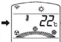
√C Auto Operation Mode
(① LED lamp ON)
1 Press the Start/Stop Button.

natural_image
Technical line drawing of a mechanical component with grooves and a curved edge (no text or symbols)- Two short beeps will sound and the operation lamp will light up.
2 Select Auto Operation.
Press the Operation Mode Selection Button.
Each time the button is pressed, operation mode is shifted in the arrow direction.
flowchart
graph LR
    A["Operation Display"] --> B["Cooling Operation"]
    B --> C["Soft Dry Operation"]
    C --> D["Heating Operation"]
Heating Operation (Heat pump model only)
3 Set the temperature.
text_image
A +H -IL- Operation mode, set temperature and fan speed are automatically set by Fuzzy rule on the basis of sensing the room temperature.
- If you want to change the set temperature, press room temperature setting button.
- The cooler or warmer you feel, the more times (up to two times) you press the button.
- Then the set temperature will be changed automatically by micom control.

To raise the Temperature. (When you feel too cool or cold)
To lower the Temperature. (When you feel too warm or hot)
4 During Auto Operation.
- It is impossible to switch the indoor fan speed during Auto Operation because of being already set to the best position by Fuzzy rule.
- If the room air conditioner is not operating as desired, switch to cooling mode or other mode.
- During Auto Operation, pressing the Air-flow direction control button makes vertical louver swings up and down automatically according to 1/f rhythm. If you want to stop the 1/f swing of the vertical louver, press again the Airflow Direction Control Button.
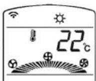
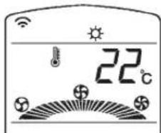
D Heating Operation Mode (Heat pump model only)
(① LED lamp ON)
1 Press the Start/Stop Button.

natural_image
Technical line drawing of a mechanical component with threaded ends and mounting holes (no text or symbols)- Two short beeps will sound and the operation lamp will light up.
2 Select Heating Operation.
Press the Operation Mode Selection Button.
Each time the button is pressed, the operation mode is shifted in the arrow direction.
Operation Display

Cooling Operation
Soft Dry Operation

Auto Operation
Heating Operation
(Heat pump model only)
3 Set the temperature.
text_image
22°C- The temperature can be set within a range of 16°C\~30°C by 1°C.

To raise the Temperature
To lower the Temperature
4 Set the fan speed.
text_image
22℃- Select the fan speed in four steps -low, medium, high, Auto.
• The display shows high fan speed.
• Each time the button is pressed, the fan speed mode is shifted.
/E FAN Operation
(① LED lamp ON)
1 Press the Start/Stop Button.


text_image
Deep Deep- Two short beeps will sound and the operation lamp will light up.
2 Press FAN Operation Button.
3 Each time Indoor Fan Speed Selector is pressed, the fan speed mode is shifted in the arrow direction.
flowchart
graph TD
    A["Signal"] --> B{Frequency mixing}
    B --> C["Auto charging mode"]
    C --> D["Output: +/-"]
- Fan speed is low.
- Fan speed is medium.
- Fan speed is high.
• Auto Air : Fan speed is automatically changed from medium to low speed, or vice versa, depending on the ambient temperature.

LED lamp ON)
Remote Controller

text_image
24°C p.m. 12:00 7 Hm. RESET- The Sleep Mode will be operated at a low fan speed(Cooling) or a med. fan speed(Heating) for quiet sleeping.
Press the Sleep Mode Auto Button.
text_image
Beep Beep- Press the Sleep Mode Auto Button and set the time to turn off.
- Check the Sleep Mode Auto LED of the room air conditioner lights up.
- The Timer is programmed by 1 hour each pressing the sleep mode auto button from 1 hour to 7 hours.
In Cooling mode
- The setting temperature will be automatically raised by 1°C 30 minutes later and by 2°C 1 hour later for comfortable sleeping.
- In order to cancel the Sleep Mode, press the button several times until star pictograph on the operation display disappears.

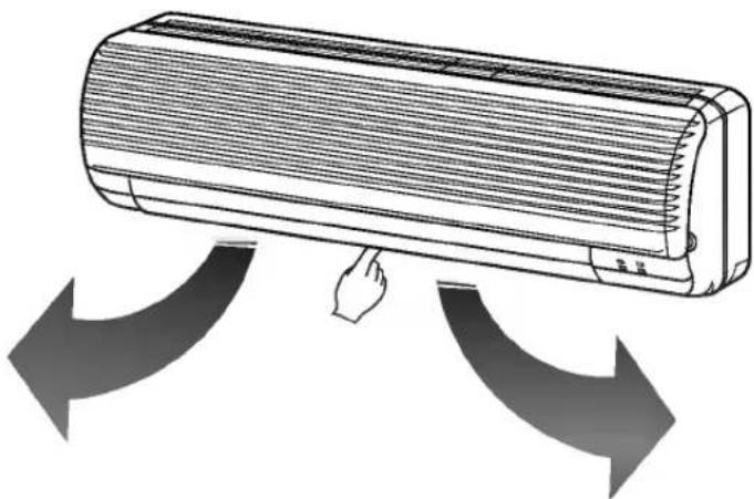
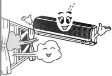
Vertical Airflow Direction Control
Airflow Direction Control
The airflow direction can be adjusted as desired by using the remote controller. This is effective when you want to cool yourself directly, such as after taking a bath.

natural_image
Illustration of a wall-mounted air conditioner unit with airflow direction indicated by an arrow (no text or symbols)1 Press the Start/Stop Button. (Confirm the unit on operation.)
2 Press the Airflow Direction Control Button and the vertical louvers swing up and down automatically.
3 Press again the Airflow Direction Control Button to set the vertical louver at the desired airflow direction.
Caution
• Always use the remote controller to adjust the airflow direction. Manually moving the vertical airflow direction louver by hand could cause operation errors.
- When air conditioner operation is stopped, the vertical airflow direction louver will close the air outlet vent of room air conditioner.
B Horizontal Airflow Direction Control
- Adjust the horizontal airflow direction by manually moving the horizontal airflow direction louver by hand.
natural_image
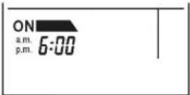
Illustration of a wall-mounted air conditioner with airflow arrows indicating cooling or ventilation (no text or symbols)The present time can be set only when pressing the reset button or when replacing batteries for the remote controller.
1 Press the Start/Stop Button after pressing the RESET Button or changing batteries for Remote Controller.

2 Press the Time Setting Button until being set the desired time.
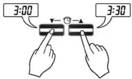
text_image
3:00 3:303 Press the Time SET Button.

NOTE : Check a.m. and p.m. Indicator in setting time.

LED lamp ON)
Remote Controller
1 ON Timer Button or OFF Timer Button
2 Time Setting Button
3 Timer SET Button
4 Timer CANCEL Button

text_image
Heat pump model Cooling model 1 2 3 4 ON - OFF SET - CANCEL C RESET1 Press the ON Timer Button or OFF Timer Button.
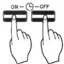
text_image
ON- OFFThe timer setting will be displayed.
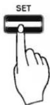
2 Change the Timer Setting and press the Timer Set Button.
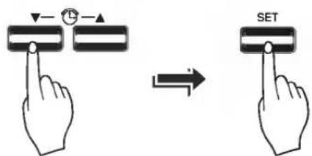
text_image
Diagram showing hand press control with SET button and directional arrow, indicating press operationTo cancel the settings
Press the Timer Cancel button.

(The timer lamp on the air conditioner and the display will go out.)
If the settings are cancelled by a power failure.
Press the Start/Stop Button, and then set the timer again as desired time according to Timer Setting Procedure.
Timer Setting Procedure
1 Confirm the present time.(Refer to page 19)
2 Press ON Timer Button or OFF Timer Button.

text_image
ON OFFDelay OFF Timer

- Select one of the following four types of operation.
Delay
ON Timer
Operation stops at OFF Timer Setting.
Delay OFF
and ON Timer
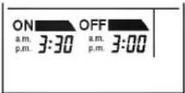
Operation starts at ON Timer Setting.
Delay ON
and OFF Timer

Operation stops at OFF Timer Setting and starts at ON Timer Setting.
Operation starts at ON Timer Setting and stops at OFF Timer Setting.
NOTE : Check a.m. and p.m. Indicator in setting time.
3 Press the Time Setting Button until being set the desired time.

text_image
3:00 3:304 Set the Timer SET Button.
(7) Operation Details
- Soft Dry Operation Mode
When the room temperature is higher than the setting temperature, it operates cooling mode as the setting temperature, the setting fan speed (if AUTO mode, then med.), and then it will be switched to Soft Dry Operation Mode when the room temperature reaches the setting temperature.
In Soft Dry Operation Mode, the indoor fan speed is automatically switched to the low.

flowchart
graph TD
    A["ROOM TEMP. SET TEMP. +1°C"] --> B["COOLING"]
    B --> C["ROOM TEMP. SOFT DRY"]
    C --> D["SET TEMP. -0.5°C"]
    D --> E["INDOOR FAN"]
    E --> F["SETTING FAN SPEED"]
    F --> G["OPERATE FOR 10MINS"]
    G --> H["STOP FOR 3 MINS"]
    H --> I["OPERATING START"]
    I --> J["OPEN OPERATIONS"]
    J --> K["OPERATE FOR 10MINS"]
    K --> L["STOP FOR 7 MINS"]
    L --> M["OPEN OPERATIONS"]
    M --> N["OPEN OPERATIONS"]
    N --> O["OPEN OPERATIONS"]
    O --> P["OPEN OPERATIONS"]
    P --> Q["OPEN OPERATIONS"]
    Q --> R["OPEN OPERATIONS"]
    R --> S["OPEN OPERATIONS"]
    S --> T["OPEN OPERATIONS"]
    T --> U["OPEN OPERATIONS"]
    U --> V["OPEN OPERATIONS"]
    V --> W["OPEN OPERATIONS"]
    W --> X["OPEN OPERATIONS"]
    X --> Y["OPEN OPERATIONS"]
    Y --> Z["OPEN OPERATIONS"]
    Z --> AA["OPEN OPERATIONS"]
    AA --> AB["OPEN OPERATIONS"]
    AB --> AC["OPEN OPERATIONS"]
    AC --> AD["OPEN OPERATIONS"]
    AD --> AE["OPEN OPERATIONS"]
    AE --> AF["OPEN OPERATIONS"]
    AF --> AG["OPEN OPERATIONS"]
    AG --> AH["OPEN OPERATIONS"]
    AH --> AI["OPEN OPERATIONS"]
    AI --> AJ["OPEN OPERATIONS"]
    AJ --> AK["OPEN OPERATIONS"]
    AK --> AL["OPEN OPERATIONS"]
    AL --> AM["OPEN OPERATIONS"]
    AM --> AN["OPEN OPERATIONS"]
    AN --> AO["OPEN OPERATIONS"]
    AO --> AP["OPEN OPERATIONS"]
    AP --> AQ["OPEN OPERATIONS"]
    AQ --> AR["OPEN OPERATIONS"]
    AR --> AS["OPEN OPERATIONS"]
    AS --> AT["OPEN OPERATIONS"]
    AT --> AU["OPEN OPERATIONS"]
    AU --> AV["OPEN OPERATIONS"]
    AV --> AW["OPEN OPERATIONS"]
    AW --> AX["OPEN OPERATIONS"]
    AX --> AY["OPEN OPERATIONS"]
- Auto Air
For fresh cooling more than other modes.
Press the Indoor Fan Speed Selector and set to Auto Air mode.
The Air flow from medium to low speed, or reversely by the room temperature.
The set temperature goes up by time automatically.
This mode economizes power consumption and prevents over-cooling (below Fig).
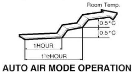
text_image
Room Temp. 0.5°C 0.5°C 1HOUR 1½HOUR AUTO AIR MODE OPERATIONFORCED OPERATION
Operation procedures when the remote controller can't be used.
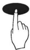
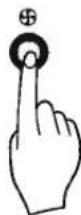
Open the front panel upward and press the Forced Operation Button.
If you want to stop operation, press again. During Forced operation, the operating conditions are automatically set as the following:
natural_image
Illustration of a person installing or adjusting a large solar panel on the air, with a smaller fire extinguisher nearby (no text or symbols)| Cooling Model | Heat pump Model | |||
| Room Temp. ≥ 24°C | 24°C > Room Temp. ≥ 21°C | Room Temp. < 21°C | ||
| Operating mode | Cooling | Cooling | Soft Dry | Heating |
| FAN Speed | High | High | Soft Dry Rule | High |
| Setting Temp. | 22°C | 22°C | Air Intake Temperature. | 24°C |

text_image
Forced Operation Button Open the front panel upwardPress the Forced Operation Button.
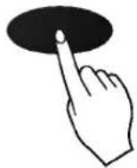
natural_image
Illustration showing a hand pressing a button on a circular object, with arrows indicating direction (no text or symbols)- Press the Forced Operation Button once again to stop operation.
Helpful information
Airflow speed and cooling capacity
The cooling capacity indicated in the specification is the value when the fan speed is set to high, and the capacity will be lower at low or medium fan speed.
High fan speed is recommended when you wish to cool the room quickly.
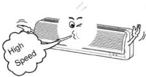
text_image
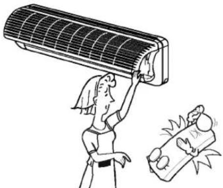
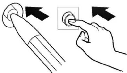
High SpeedBefore performing any maintenance procedure
■ Disconnect the power plug or turn off the breaker.

natural_image
Illustration of a flat-screen air conditioner connected to a wall-mounted power outlet (no text or symbols)
CAUTION
When the unit is to be cleaned, switch off and disconnect the power plug or turn off the breaker.
Since the fan rotates at high speed during operation, it may cause an injury.
■ Clean using soft dry cloth.
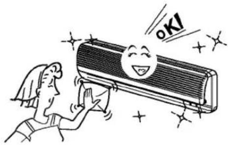
natural_image
Cartoon illustration of a person cleaning a large air conditioner with a smiling face and 'OK!' text (no other text or symbols)■ Never use any of the followings:
• Water hotter than 40°C.
Could cause deformation and/or discoloration.
- Volatile substances. Could damage the surfaces of the air conditioner.

text_image
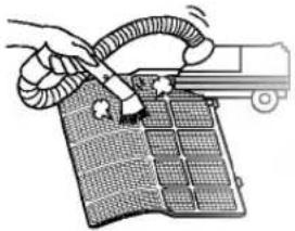
Benzene POWER SCOURING CLEAR ClearbarCleaning the air filter (about once every 2 weeks)

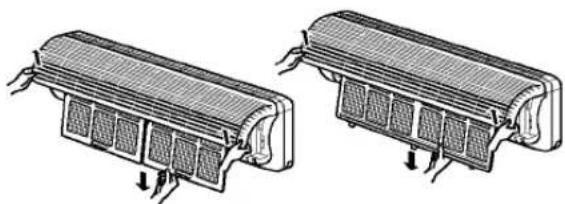
Remove the Air filters.
■ Take hold of the tab and pull slightly forward to remove the filter.
natural_image
Technical illustration of two heat exchangers with cooling fins and heat sinks (no text or symbols)
CAUTION
When the air filter is to be removed, do not touch the metal parts of the indoor unit. It may cause an injury.

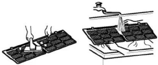
Clean dirt from the air filter using a vacuum cleaner of by washing with water.
■ If dirt is conspicuous, wash with a solution of detergent in lukewarm water.
If hot water (50°C or more) is used, it may be deformed.
natural_image
Illustration of two steps to process a thermal or mechanical component, showing heating and cooling (no text or symbols present)
After washing with water, dry well in the shade.
■ Do not expose the air filter to direct sunlight or heat from a fire when drying it.

natural_image
Illustration of a window with curtains and two solar panels mounted on a surface (no text or symbols)
Install the air filter.
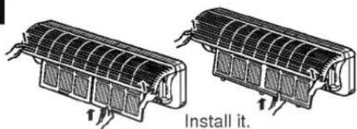
text_image
Install it.WHEN THE AIR CONDITIONER IS NOT GOING TO BE USED FOR A LONG TIME.

Operate the air conditioner at the following settings for 2 to 3 hours.
- Type of operation: Fan operation mode.(refer to page 16)
natural_image
Cartoon illustration of a smiling air conditioner with motion lines (no text or symbols)This will dry out the internal mechanisms.

Turn off the breaker, and disconnect the plug.


Turn off the breaker when the air conditioner is not going to be used for a long time.
Dirt may collect and may cause a fire.

Remove the batteries from the remote controller.

natural_image
Diagram showing a device with battery modules and two separate cylindrical components (no text or symbols)
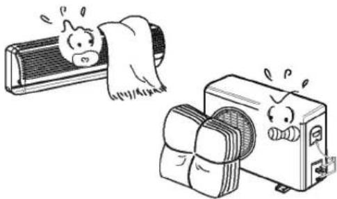
Clean the air filter and install it in the indoor unit.
(Refer to page 24 for cleaning it.)

text_image
Clean it before installing.
Check that the air inlet and outlet of the indoor/outdoor unit are not blocked.
natural_image
Cartoon illustration of a cow and a washing machine (no text or symbols)
Check that the ground wire is connected correctly. It may be connect to the indoor unit side.

Apply grounding.
Do not connect a grounding wire to a gas pipe, water pipe, lightning rod or ground wire of a telephone. If a grounding is incorrect, it may cause an electric shock.
Helpful information
The air filters and your electric bill.
If the air filters become clogged with dust, the cooling capacity will drop, and 6% of the electricity used to operate the air conditioner will be wasted.
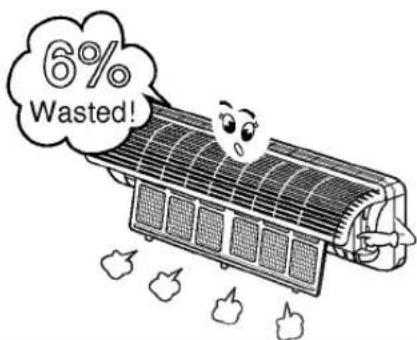
text_image
6% Wasted!| This is not good for the health and wastes electricity. | Do not let direct sunshine enter the room when the air conditioner is in operation. | Adjust the vertical and horizontal airflow direction to ensure a uniform temperature in the room. |
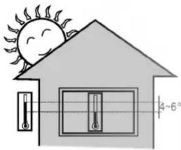 |  |  |
| Avoid opening doors and windows as much as possible to keep the cool air in the room. | Blockages in the air filter reduce the airflow and lower cooling and dehumidifying effects. Clean at least once every two weeks. | Since windows are kept closed, it is a good idea to open them and ventilate the room now and then. |
 |  |  |
BEFORE CALLING FOR SERVICE
Check the following points before requesting repairs or service.... If the malfunction persist, please contact your dealer.

text_image
Have you made a mistake in timer operation? Has the fuse blown or has the circuit breaker been tripped? Check that this is not a damp smell exuded by the walls, carpet, furniture or cloth items in the room. Condensation occurs when the airflow from the air conditioner cools the warm room air. This is the protector of the mechanism. Wait about three minutes and operation will begin. Is the air filter dirty? See air filter cleaning instructions. The room may have been very hot when the room air conditioner was first turned on. Allow time for it to cool down. Has the temperature been set incorrectly? Are the indoor unit's air inlet or outlet vents obstructed? For a noise that sounds like water flowing. -This is the sound of freon flowing inside the air conditioner unit. For a noise that sounds like the compressed air releasing into atmosphere. -This is the sound of the dehumidifying water being processed inside the air conditioning unit. Are the batteries depleted? Are the batteries inserted in the opposite (+) and (-) directions? This sound is generated by the expansion/constriction of the front panel, etc. due to changes of temperature.NOTE
SPLASH PROOF : The outdoor side of this appliance is SPLASH PROOF and the indoor side is ordinary.
General Electric Company, Appliance Park, Louisville, KY, 40225 USA
Models:
Outdoor units Indoor units
AG0AC11BKO AG1AC11BKM
AG0AC13BKO AG1AC13BKM
60Hz, 220Volts
Models:
Outdoor units Indoor units
AG0AC07BWO AG1AC07BWF/G/I
AG0AC09BWO AG1AC09BWF/G/I
AG0AC12BWO AG1AC12BWF/G/I
50Hz, 220-240Volts
Models:
Outdoor units Indoor units
AG0AH07BWO AG1AH07BWF/G/I
AG0AH09BWO AG1AH09BWF/G/I
AG0AH12BWO AG1AH12BWF/G/I
50Hz, 220-240Volts
49-7323
Printed in Korea