VTD-HOCR6E2812V - Security Camera Vitek - Free user manual and instructions
Find the device manual for free VTD-HOCR6E2812V Vitek in PDF.

User questions about VTD-HOCR6E2812V Vitek
0 question about this device. Answer the ones you know or ask your own.
Ask a new question about this device
Download the instructions for your Security Camera in PDF format for free! Find your manual VTD-HOCR6E2812V - Vitek and take your electronic device back in hand. On this page are published all the documents necessary for the use of your device. VTD-HOCR6E2812V by Vitek.
USER MANUAL VTD-HOCR6E2812V Vitek
natural_image
Two VITEK security cameras shown from different angles (no text or symbols visible on the devices themselves)FEATURES:
• 1/2.9" Sony® Progressive Scan CMOS (IMX222)
• 2.1 MegaPixel with Full 1080p/720p HD-SDI (SMPTE292M) / EX-SDI Output
- Six (6) High Power 850nm IR LEDs with up to 160' foot range
• MegaPixel IR Corrected 2.8-12mm Varifocal Lens Included
• Mechanical IR Cut Filter (True Day/Night)
• 16:9 Video Format
- Advanced OSD Functions: Motion Detection, Sharpness, Gamma, Mirror, Flip, DSS, Freeze, D-Zoom, ACE, WDR, 3D-DNR, Defog, Privacy, HLM
• 100% Pure Digital Transmission of video data
- Up to 1000' HD Transmission Range (Depending on cable characteristics and integrity)
• IP68 Weather Resistance
• 12VDC/24VAC Dual Voltage Operation
• Available in Ivory or Black
Safety Precaution
- To prevent electrical shock and risk of fire hazards, do not expose this unit to rain or moisture and only use specified power source..

text_image
CAUTION RISK OF ELECTRIC SHOCK . DO NOT OPEN CAUTION: TO REDUCE THE RISK OF ELECTICAL SHOCK, DO NOT REMOVE COVER (OR BACK). NO USER SERVICEABLE PARTS INSIDE. REFER SERVICING TO QUALIFIED SERVICE PERSONNEL
The symbol is intended to alert the user to the presence of uninsulated "dangerous voltage" within the product's enclosure that may be of sufficient magnitude to constitute a risk of electrical shock.
The symbol is intended to alert the user to the presence of important operating and maintenance (servicing) instructions in the literature accompanying the unit.
- Warning :
This equipment has been tested and found to comply with the limits for a Class A digital device, pursuant to part 15 of the FCC Rules. These limits are designed to provide reasonable protection against harmful interference when the equipment is operated in a commercial environment. This equipment generates, uses, and can radiate radio frequency energy and, if not installed and used in accordance with the instruction manual, may cause harmful interference to radio communications. Operation of this equipment in a residential area is likely to cause harmful interference in which case the user will be required to correct the interference at their own expense.
- Caution :
Any changes or modifications in construction of this device which are not expressly approved by the party responsible for compliance could void the user's authority to operate the equipment.
Main power quality should be that of a typical commercial environment. If the user of the model requires continued operation during power interruptions, it is recommended that the device be powered from an uninterruptible power supply (UPS).
Safety Precaution

NOTICE
- The image used in this instruction manual are processed to help comprehension and may differ from actual video of the camera.
- Avoid installing in areas where shock or vibration may occur.
- Pay attention to safety when running the connection cables and make sure that the cables are not subject to heavy loads, kinks, moisture or damage.
- Never open the device (no user serviceable parts inside). The warranty becomes void if repairs are undertaken by unauthorized persons.
- Maintenance and repair have to be carried out only by authorized service centers.
- Use only a mild detergent to clean the housing.
- The camera should never be operated beyond the technical specifications. This can lead to damaging the device and void the warranty.
• The camera should never be operated in water.
Contents
p. 2\~3 Safety Precaution
p. 4 Contents
p. 5 Dimensions
p. 6 Installation Instructions
p. 7 Zoom & Focus Pan & Tilt
p. 8 Attaching the Dome
p. 9 Using the OSD Controller
p. 10 Menu Set Up
p. 10-24 Operating Instructions
p. 25 Specifications
p. 26 On Cue VT-HDOCE Series
p. 27 Limited Product Warranty
Dimensions
(unit : inches)

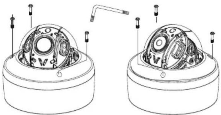
Installation Instructions
The Installation method is the same for the Varifocal and Fixed lens camera. The product dimensions are the same for either camera.
- Place the mounting template at the installation position and drill the ceiling or wall if needed.
- Open the dome cover by loosening screws. Use the torque wrench supplied.
natural_image
Technical line drawing of two mechanical components with internal components and mounting holes (no text or symbols)IR cover integral Type
IR cover separable Type
text_image
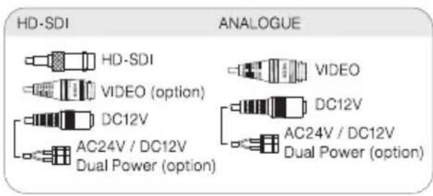
HD-SDI ANALOGUE HD-SDI VIDEO (option) DC12V AC24V / DC12V Dual Power (option) VIDEO DC12V AC24V / DC12V Dual Power (option)
text_image
CONNECTION OSD (Option) White (485-) Orange (485+) Joystick (Option)Installation Instructions
Zoom & Focus (Varifocal)
- While the camera is open using a phillips screw driver loosen the screw to adjust the Zoom & Focus as shown in the images below.
- Tighten the screw to hold desired Zoom & Focus position.
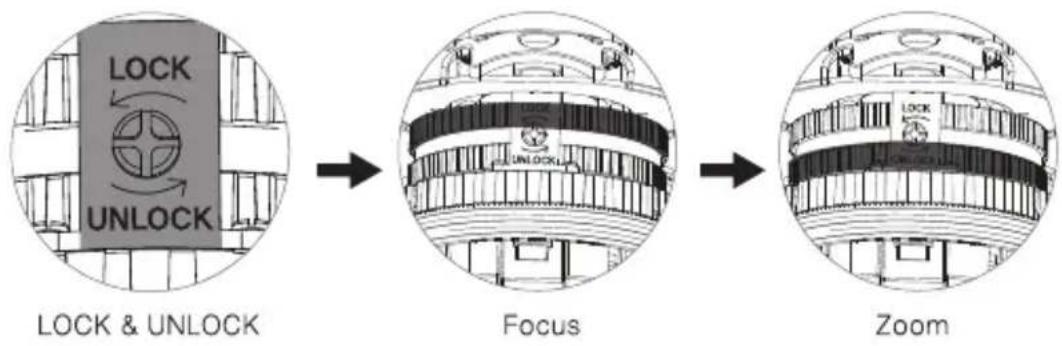
flowchart
graph LR
    A["LOCK & UNLOCK"] --> B["Focus"]
    B --> C["Zoom"]
text_image
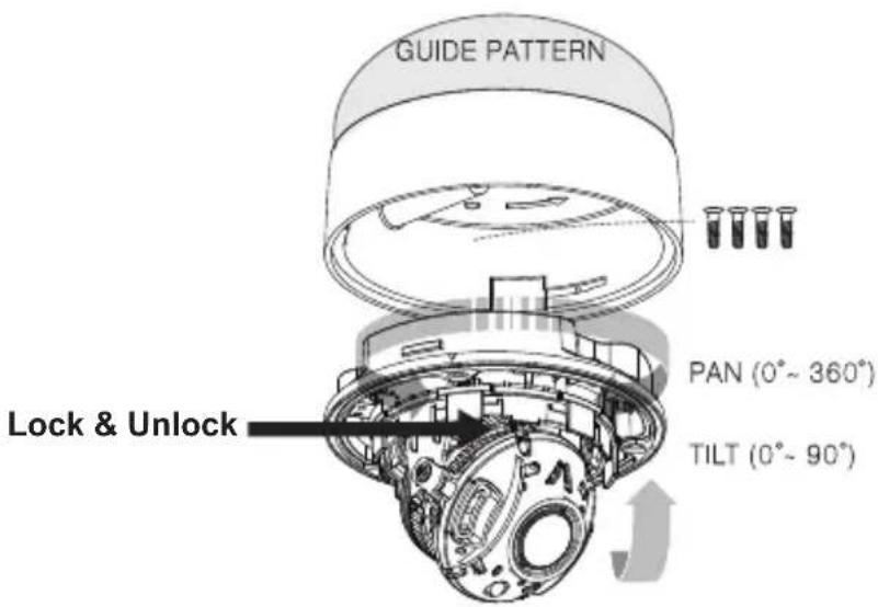
GUIDE PATTERN PAN (0°~ 360°) TILT (0°~ 90°) Lock & UnlockLimit of Pan & Tilt
1) Pan limit:
Pan is limited to +/- 360°. Do NOT force the gimbal over the limit, this will prevent internal damage.
2) Tilt limit:
Tilt is limited to 0^ min 90^ max. with reference to the ceiling when the inclination of camera module is 0^ , that is, the image is aligned horizontally.
Installaton Instructions
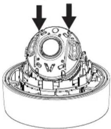
Attaching the Dome
There are 2 locations of the Hemisphere Guide in the IR dome cover.
- To attach the dome cover line up the Hemisphere Guides as shown below.
- Attach the dome cover to the dome base unit and tighten the assembly screws using the torque wrench.
Hemisphere Guides
natural_image
Technical illustration of a mechanical assembly with two downward arrows indicating motion or force (no text or symbols present)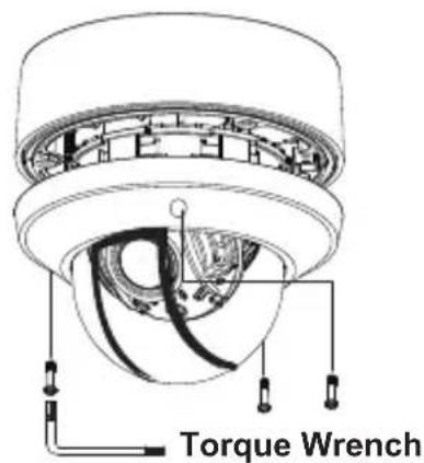
text_image
Torque Wrench
natural_image
Technical line drawing of a mechanical component with concentric rings and mounting holes (no text or symbols)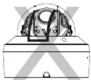
natural_image
Technical line drawing of a mechanical device with no visible text or symbolsCorrect Assembly Incorrect Assembly
! CAUTION
- If the Hemisphere Guides are not correctly assembled you may see a diffused reflection.
- Please line up the Hemisphere Guides as instructed for correct view.
Operating Instructions
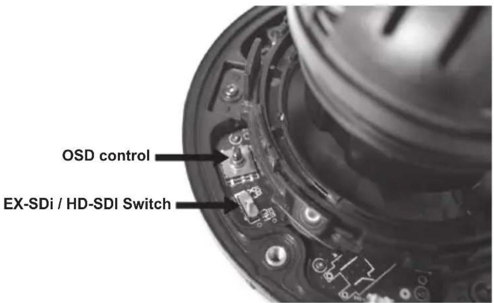
Using OSD controller
- Setup menu can be accessed and controlled by OSD control joy stick on the inside of camera unit.
- EX-SDI / HD-SDI switch is located on the inside of camera unit.
text_image
OSD control EX-SDi / HD-SDI SwitchMENU
| SETUP MENU | |||||||
| EXPOSURE | LENS | BRIGHTNESS | SHUTTER | SENS-UP | AGC | ||
| WHITE BAL | AWB | COLOR GAIN | |||||
| IMAGE | SHARPNESS | GAMMA | MIRROR | FLIP | FREEZ | D-ZOOM | ACE |
| DEFOG | SHADING | PRIVACY | |||||
| BACKLIGHT | OFF | WDR | BLC | HLC | |||
| DAY&NIGHT | AUTO | COLOR | B/W | EXTERN | |||
| DNR | OFF | HIGH | MIDDLE | LOW | |||
| MOTION | OFF | SET | |||||
| SERIAL | CAM ID | ID DISPLAY | BAUDRATE | ||||
| SYSTEM | DEFECT DET | IMAGE SCALE | COLOR SPACE | VIDEO | FRAME RATE | ||
| LANGUAGE | CAM TITLE | FCM MODE | FACTORY SET | ||||
| EXIT | |||||||
Above specifications may be changed without any notice.
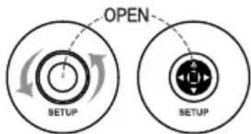
OSD SETTINGS
text_image
OPEN SETUP SETUPOutside type (bullet)
To Setup, turn the cover counter-clockwise.
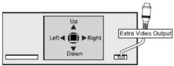
text_image
Up Left←Right Down Extra Video OutputInside type (dome)
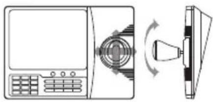
natural_image
Diagram showing a device with a keypad and a bell icon, connected to a screen (no text or symbols present)- Call OSD MENU: 1. Call #95
- Open button
• Zoom in : Tele button or Joystick
• Zoom out : Wide button or Joystick
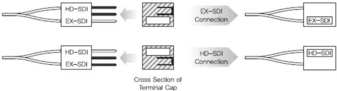
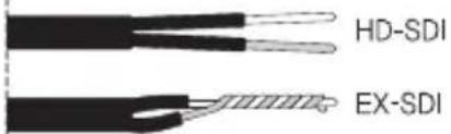
How to connect by using the Ex-sdi and hd-sdi cable
cable type 01
flowchart
graph LR
    A["HD-SDI"] --> B["EX-SDI"]
    C["EX-SDI"] --> B
    B --> D["Cross Section of Terminal Cap"]
    E["EX-SDI Connection"] --> F["HD-SDI"]
    G["EX-SDI"] --> H["HD-SDI"]
    I["HD-SDI"] --> J["HD-SDI"]
cable type 02
text_image
HD-SDI EX-SDIswitch type
EX-SDI

HD-SDI
RS-485
Using a RS-485 communication, it will be able to control the OSD menu at the System Controller or DVR.
(1) The case which it controls from the PC
Using a RS-485 converter, It connects to RS-485 control cable outside camera and serial cable EX) SERIAL PORT OF THE PC(COM1) → SERIAL CABLE → RS-485 CONVERTER → RS-485 CONTROL CABLE
(2) The case which it controls from the DVR or System Controller It connects the RS-485 control cable in the connection terminal of 485 control boards which are connected with the DVR or System Controller.
| 485 Control Board Connection Port | RS-485 Control Port |
| (+) CONNECTION TERMINAL (R+) | 485+ |
| (-) CONNECTION TERMINAL (R-) | 485- |
▶ RS-485 Communication establishment initial value
| Item | Camera ID | BAUD RATE | UART MODE | RET PKT |
| Initial value | 0 | 9600 | 8-NONE-1 | Not supported |
- When you construct external control systems for a camera control, please use to the PROTOCOL or PELCO-D PROTOCOL.
- When you connecting to RS-485 control cable, please peel off the outer skin inside the RS-485 control cable.
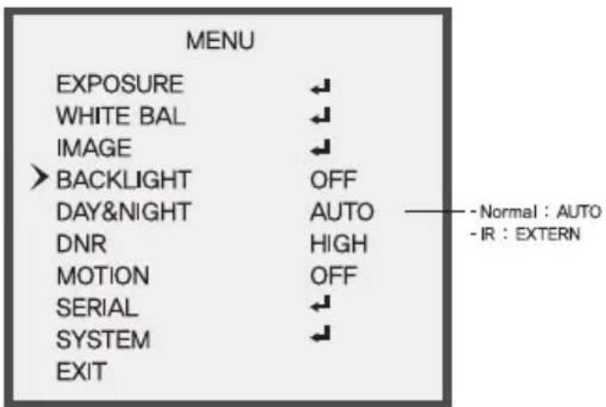
MENU

text_image
MENU Select any function you wish to operate by pushing the joystick Up or Down. EXPOSURE WHITE BAL IMAGE BACKLIGHT DAY&NIGHT DNR MOTION SERIAL SYSTEM EXIT Modes can be changed pushing the joystick Right or Left. AUTO HIGH OFF Normal : AUTO -IR : EXTERN-
Please press the SET button
-
Settings can now be made. The SET menu is displayed on the monitor.
• To run the OSD menu, please press and hold the SET button for three seconds. -
Please select any function you wish to activate by pushing the button Up or Down
- The cursor position will appear green on your screen.
You can push the button Up or Down to change function you wish to change.
- Please press the button Right or Left if you wish to change mode.
- When the button is pressed Right or Left, available values and mode are displayed in order. Please keep press the button until you get the mode you wish.
- Please select "EXIT" and then press the button to finish the setting.
SETUP
- EXPOSURE, WHITE BAL, IMAGE, BACKLIGHT, DAY&NIGHT, DNR, MOTION SERIAL, SYSTEM, EXIT control can be selected.
- When the MAIN MENU is on the screen, please position the cursor to SETUP by using the button. And then press the button.
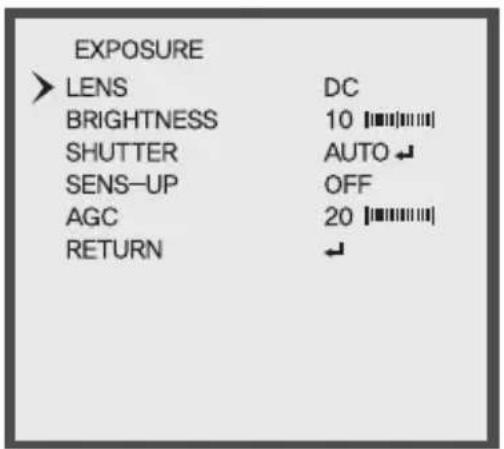
EXPOSURE
- When the SETUP menu screen is displayed, select EXPOSURE by using the Up and Down buttons so that arrow indicates EXPOSURE.
- Select a desired mode using the Right and Left buttons.

text_image
MENU > EXPOSURE WHITE BAL IMAGE BACKLIGHT DAY&NIGHT DNR MOTION SERIAL SYSTEM EXIT ↓ ↓ ↓ OFF AUTO HIGH OFF ↓ ↓ Normal : AUTO -IR : EXTERNFIX / MV
text_image
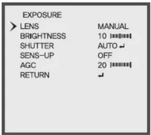
EXPOSURE LENS MANUAL BRIGHTNESS 10 [||||||||] SHUTTER AUTO ← SENS-UP OFF AGC 20 [||||||||] RETURN ←V/F
text_image
EXPOSURE ➢ LENS DC BRIGHTNESS 10 SHUTTER AUTO SENS-UP OFF AGC 20 RETURN ↓- LENS: When using BUILT-IN LENS, the type of the lens is able to fix. (DC / MANUAL)
• BRIGHTNESS : Left Key (Level DECREMENT), Right Key (Level INCREMENT) - SHUTTER
- AUTO : MODE (DEBLUR / NORMAL)
- FLICKER : Select this when you experience picture flicker, which can happen when there is a clash with the frequency of the installed lighting.
- MANUAL : SPEED (1/30, 1/60, 1/120, 1/250, 1/700, 1/1000, 1/1600, 1/2500, 1/5000, 1/7000, 1/10000, 1/30000)
- SENS_UP : OFF / X2 / X4 / X8 / X16 / X32
- Sens-up is realized in the most low illumination quality and it provides the image without a noise at the low illumination quality.
- When it is night or dark, the camera automatically detects the light level and maintains a clear picture if this mode is activated.
- When "SENS_UP" is on, shutter cannot be adjusted.
- AGC (Auto Gain Control) : The higher the gain level, the brighter the screen - but the higher the noise.
WHITE BAL
• Use the White Balance function to adjust the screen color.
- When the SETUP menu screen is displayed, select 'White Bal.' by using the Up and Down buttons so that the arrow indicates 'White Bal.'
- Select a desired mode using the Right and Left buttons.

text_image
MENU EXPOSURE WHITE BAL IMAGE BACKLIGHT DAY&NIGHT DNR MOTION SERIAL SYSTEM EXIT Normal : AUTO -IR : EXTERN- AWB
- AUTO : Default - This function continuously adjusts the white balance automatically to adapt to changes in lighting conditions,
- AUTOext: It is a mode to do a halogen and the special lighting to White detection.
- PRESET: This function adjusts the white balance regardless of the subject conditions.

text_image
WHITE BAL > AWB COLOR GAIN RETURN MANUAL ↓ 10 ||||||||| ↓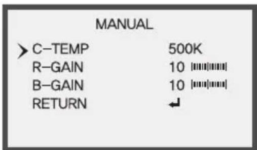
text_image
MANUAL >C-TEMP 500K R-GAIN 10||||||||| B-GAIN 10||||||||| RETURN ↓- MANUAL - KELVIN : LOW / MIDDLE / HIGH
- R-GAIN: Left Key (Level DECREMENT), Right Key (Level INCREMENT)
- B-GAIN : Left Key (Level DECREMENT), Right Key (Level INCREMENT)
- COLOR GAIN : Control 0 to 20 by right and left button.
IMAGE
- SHARPNESS, GAMMA, MIRROR, FLIP, FREEZ, D-ZOOM, ACE, DEFOG, SHADING, PRIVACY, REYURN control can be selected.

text_image
MENU EXPOSURE WHITE BAL > IMAGE BACKLIGHT DAY&NIGHT DNR MOTION SERIAL SYSTEM EXIT ← ← ← OFF AUTO HIGH OFF ← ← - Normal : AUTO - IR : EXTERN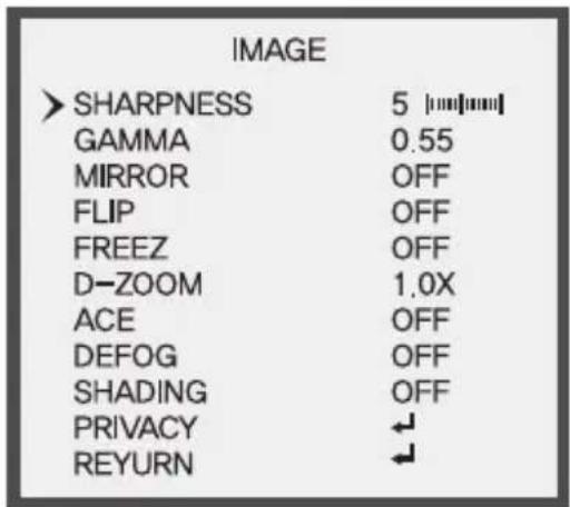
text_image
IMAGE > SHARPNESS 5 [mm/mm] GAMMA 0.55 MIRROR OFF FLIP OFF FREEZ OFF D-ZOOM 1.0X ACE OFF DEFOG OFF SHADING OFF PRIVACY ← REYURN ←- SHARPNESS: Control 0 to 10 by right and left button.
• GAMMA : Adjust Gamma value. (0.45 / 0.50 / 0.55 / 0.60 / 0.65 / 0.70 / 0.75)
• MIRROR / FLIP : You can select function by using LEFT or RIGHT button.

OFF

MIRROR (ON)

FLIP (ON)
- FREEZE: The video can be stopped.
• D-ZOOM: You can use a digital zoom of 1.0x \~ 16.0x
- ACE (Adaptive Color & Contrast Enhancement) : OFF, LOW, MIDDLE, HIGH
ACE black performs an image Enhancement processing to enhance visibility of an image by changing the brightness values to the level that people can recognize the change. This processing technique is equivalent to the dynamic range reduction technique. Which converts the HDR (High Dynamic Range) into the restricted LDR (Low Dynamic Range)
text_image
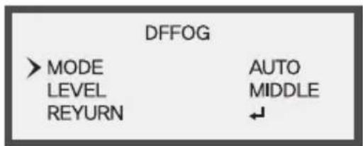
DFFOG > MODE LEVEL REYURN AUTO MIDDLE ↓- DEFOG : MODE (you can select AUTO / MANUAL) LEVEL (you can select LOW / MIDDLE / HIGH)
- SHADING: When using wide angle lens, you can compensate darkness of corner on the screen.
text_image
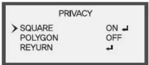
PRIVACY > SQUARE ON ↓ POLYGON OFF REYURN ↓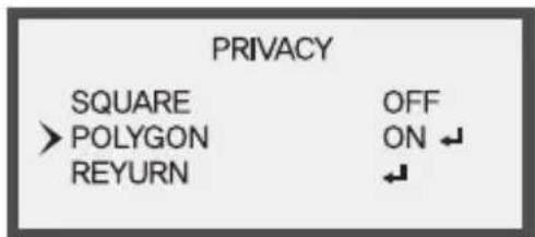
text_image
PRIVACY SQUARE OFF > POLYGON ON ↓ REYURN ←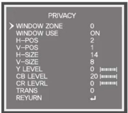
text_image
PRIVACY > WINDOW ZONE 0 WINDOW USE ON H-POS 2 V-POS 1 H-SIZE 14 V-SIZE 8 Y LEVEL 0 [########] CB LEVEL 20 [########] CR LEVRL 0 [########] TRANS 0 REYURN ←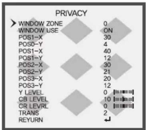
- PRIVACY: This modes conceals the areas you do not wish to appear on the screen.
-WINDOW ZONE : Select the region to apply Privacy (0\~15)
-WINDOW USE : you can select (ON/OFF)
-SQUARE : H-POS, V-POS, H-SIZE, V-SIZE
You can move the position of the range that you selected in the WINDOW ZONE to Left, Right, Up, Down.
You can move the position of the range that you selected in the WINDOW ZONE to Left, Right, Up, Down.
-Y LEVEL : Control 0 to 20 right and left button.
-CB LEVEL, CR LEVEL : The color gain controls CB, CR level.
-TRANS: Adjust TRANS value. (0, 1, 2, 3)
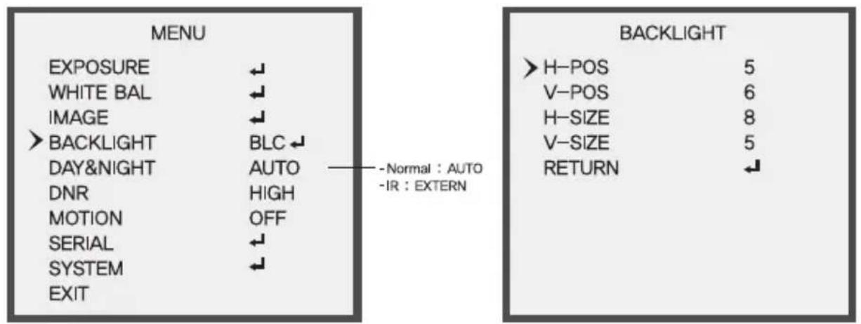
BLACKLIGHT
text_image
MENU EXPOSURE WHITE BAL IMAGE > BACKLIGHT DAY&NIGHT DNR MOTION SERIAL SYSTEM EXIT OFF AUTO HIGH OFF Normal : AUTO - IR : EXTERN
text_image
MENU EXPOSURE WHITE BAL IMAGE > BACKLIGHT DAY&NIGHT DNR MOTION SERIAL SYSTEM EXIT HLC AUTO HIGH OFF ↓ ↓ ↓ - Normal : AUTO - IR : EXTERN BACKLIGHT > LEVEL 10 [mm/mm] COLOR BLK RETURN ↓• HLC (High Light Compensation)
Function is being prevented against headlights of vehicle effectively. it is the most suitable function to see license plates at night.
- LEVEL: You can set the level point of HLC
text_image
MENU EXPOSURE ← WHITE BAL ← IMAGE ← > BACKLIGHT BLC ← DAY&NIGHT AUTO — Normal : AUTO DNR HIGH MOTION OFF SERIAL ← SYSTEM ← EXIT - Normal : AUTO - IR : EXTERN BACKLIGHT > H-POS 5 V-POS 6 H-SIZE 8 V-SIZE 5 RETURN ←• BLC (Backlight Light Compensation)
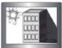
When there is a strong backlight behind the object, clear images of the background as well as the object can still be obtained by using the BLC function.
- BLC OSD : The area to apply the BLC function is shown in BOX shape.
- H-POS: You can move the range to apply BLC to Left and Right
- V-POS: You can move the range to apply BLC to Up and Down
* H-SIZE : You can increase and decrease the size of the range to apply BLC horizontally. - V-SIZE : You can increase and decrease the size of the range to apply BLC vertically.

flowchart
graph TD
    A["MENU"] --> B["EXPOSURE"]
    A --> C["WHITE BAL"]
    A --> D["IMAGE"]
    A --> E[">BACKLIGHT"]
    A --> F["DAY&NIGHT"]
    A --> G["DNR"]
    A --> H["MOTION"]
    A --> I["SERIAL"]
    A --> J["SYSTEM"]
    A --> K["EXIT"]

    L["BACKLIGHT"] --> M["WEIGHT"]
    L --> N["MIDDLE"]
    L --> O["RETURN"]

    style A fill:#f9f,stroke:#333
    style L fill:#ccf,stroke:#333

    note1["- Normal : AUTO"]
    note2["-IR : EXTERN"]
• WDR (Wide Dynamic Range) : OFF / LOW / MIDDLE / HIGH By using the WDR function, you can distinguish object in the dark.

WDR (ON)
WDR (OFF)
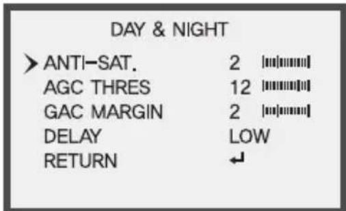
DAY & NIGHT

text_image
MENU EXPOSURE WHITE BAL IMAGE BACKLIGHT DAY&NIGHT DNR MOTION SERIAL SYSTEM EXIT OFF AUTO HIGH OFF Normal : AUTO -IR : EXTERNAUTO
EXTERN
text_image
DAY & NIGHT > ANTI-SAT. 2 [||||||||] AGC THRES 12 [||||||||] GAC MARGIN 2 [||||||||] DELAY LOW RETURN ↙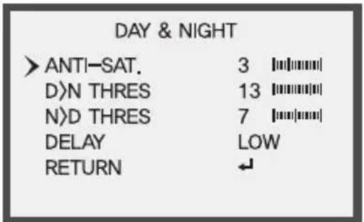
text_image
DAY & NIGHT > ANTI-SAT. 3 [||||||||] D>N THRES 13 [||||||||] N>D THRES 7 [||||||||] DELAY LOW RETURN ↙- AUTO: The camera will automatically show color image in high lux and black / white image in low lux.
- AGC THRES : It controls gain level for changing Day > Night mode.
- AGC MARGIN : It controls gain level for changing Night > Day mode.
- DELAY : D&N change on continual time condition set Day > Night or Night > Day. (HIGH, MIDDLE, LOW)
• COLOR : This picture is always displayed in color.
- B&W: The picture is always displayed in black and white. You can turn on or off the burst signal on B/W mode.
- EXTERN: Select this when the color is controlled by CDS sensor.
- ANTI-SAT. : As Smart IR function, the smaller ANTI-SAT setting value, the weaker Smart IR function,
- D)N THRES : It controls gain level for changing Day > Night mode. (0\~255)
- N>D THRES : It controls gain level for changing Night > Day mode. (0\~255)
- DELAY : D&N change on continual time condition set Day > Night or Night > Day. (HIGH, MIDDLE, LOW)
DNR
• DNR (Digital Noise Reduction)
Improve S/N ratio and more clean the low illumination quality and can be monitoring at night clearly without the image drag and noise phenomenon.
text_image
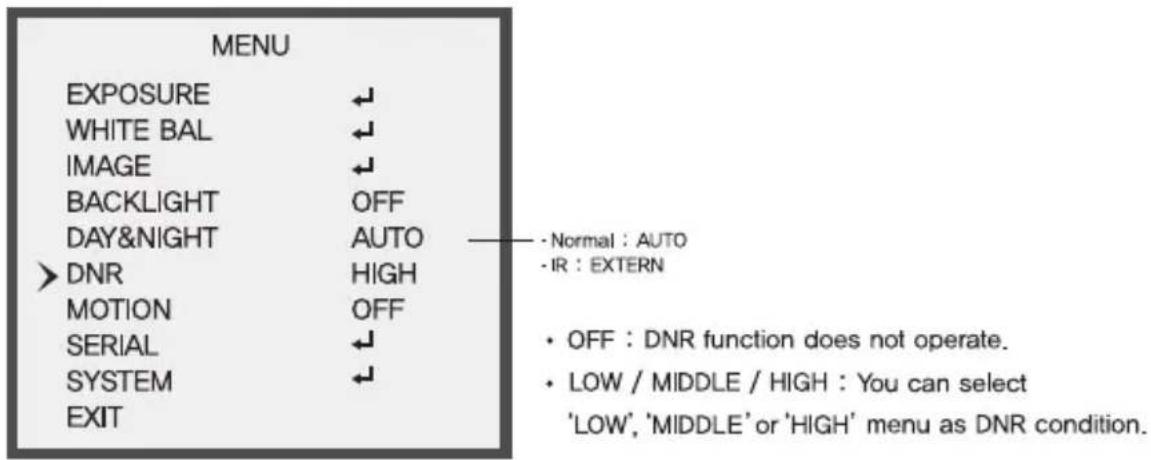
MENU EXPOSURE WHITE BAL IMAGE BACKLIGHT DAY&NIGHT DNR MOTION SERIAL SYSTEM EXIT Normal : AUTO -IR : EXTERN OFF : DNR function does not operate. LOW / MIDDLE / HIGH : You can select 'LOW', 'MIDDLE' or 'HIGH' menu as DNR condition.MOTION
Function of MOTION can designate the range of the user to detect the movement on the screen and adjust the size of the area. So, you can monitor the movement of an object on the given region more efficiently

text_image
MENU EXPOSURE WHITE BAL IMAGE BACKLIGHT DAY&NIGHT DNR MOTION SERIAL SYSTEM EXIT OFF AUTO HIGH OFF Normal : AUTO -IR : EXTERN• OFF: MOTION mode is cancelled.
- SET: Any motion in the selected areas is observed.

text_image
MOTION > AREA SENSITIVITY 5 [||||||||] TEXT ALARM OFF RETYRN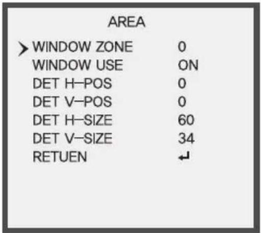
text_image
AREA > WINDOW ZONE 0 WINDOW USE ON DET H-POS 0 DET V-POS 0 DET H-SIZE 60 DET V-SIZE 34 RETUEN ↙• AREA
- WINDOW ZONE : Select the region to apply MOTION
-
WINDOW USE : you can select (ON/OFF)
-
DET H-POS : You can move the range to apply WINDOW ZONE to Left and Right
- DET V-POS : You can move the range to apply WINDOW ZONE to Up and Down
- DET H-SIZE : You can increase and decrease the size of the range to apply WINDOW ZONE horizontally.
- EEV-SIZE : You can increase and decrease the size of the range to apply WINDOW ZONE vertically.
- SENSITIVITY: Set the sensitivity of the moving detection.
SERIAL
text_image
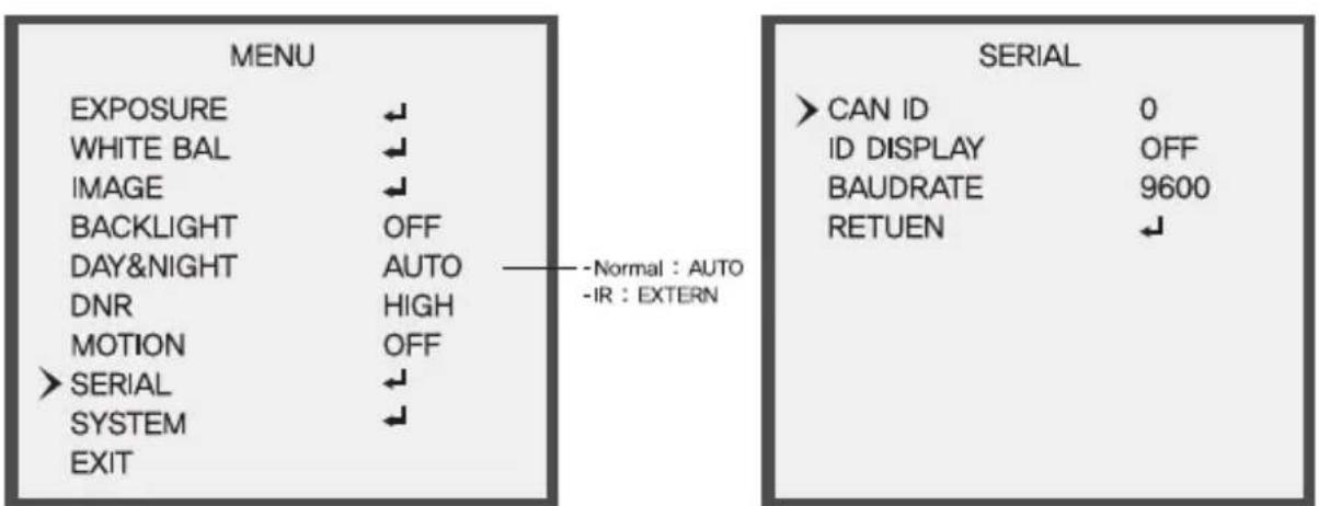
MENU EXPOSURE WHITE BAL IMAGE BACKLIGHT DAY&NIGHT DNR MOTION > SERIAL SYSTEM EXIT - Normal : AUTO -IR : EXTERN SERIAL > CAN ID 0 ID DISPLAY OFF BAUDRATE 9600 RETUEN ↓• CAM ID : You can select camera ID from 0 to 255 when using remote control.
• ID DISPLAY : You can select ID ON or OFF
- BAUDRATE : You can select 2400 / 4800 / 9600 / 57600 / 115200 bps. Support "pel-D protocol"
SYSTEM

text_image
MENU EXPOSURE WHITE BAL IMAGE BACKLIGHT DAY&NIGHT DNR MOTION SERIAL > SYSTEM EXIT Normal : AUTO -IR : EXTERN
text_image
SYSTEM >DEFFECT_DET ON IMAGE SCALE USER COLOR SPACE HD-CbCr VIDEO NTSC FRAME RATE 1080_30p LANGUAGE ENG CAM TITLE OFF FCM MODE OFF FACTORY SET ON RETUEN- DEFECT DET : DEFECT DET mode id OFF. (OFF) / Close the lens to block the light. (ON) Adjust Irft & right buttons and press "SET" button to automatically start the mode.
- IMAGE SCALE : You can select. (USER (OFFSET Levle (0\~32) / FULL / COMP)
• COLOR SPACE : You can select, (HD-Cbr / SD-CbCr / YUV)
• VIDEO : You can select. (NTSC / PAL)
• FRAME EATE : 1080P, 720P, 720 CROP
• LANGUAGE : ENG, CHN, CHN(S), JPN, KOR

text_image
CAM TITLE * 00000000 ---- U , D - CHAR SELECT L , R - POSITION ENTER - RETURN• CAM TITLE : User writes TITLE / User sets TITLE ON/OFF.
• FCM MODE

text_image
SYSTEM FCM MODE ON FACTORY SET ON RETURN ↕▶ Left box : Focus of the area of the low illumination
▶ Middle box : Focus of the area of the intermediate illumination
▶ Right box : Focus of the area of the high illumination
- If you move slowly lens, the green box will begin to appear
- When you turn the lens for the green box not to be visible, Focus is the right.
- It is possible only one box of three boxes is right.
• FACTORY SET : Factory initialize,
EXIT
- Saves all the setting menus and then exits.
Detailed Specifications
| Sensor | 1/2.9" Sony® Progressive Scan CMOS (IMX222) |
| Resolution | 2.1 MegaPixel (1080p / 720p) |
| S/N | More than 52 dB (AGC Off) |
| Video Output | Selectable: 1x HD-SDI (BNC) / EX-SDI (BNC) and 1x SD CVBS (BNC) |
| IR Illuminators | 6 High Power IR LEDs |
| IR Color Temp. | 850nm |
| IR Range | 160' |
| Dynamic Intensity Smart IR LEDs | YES |
| Lens | MegaPixel IR Corrected 2.8-12mm Varifocal |
| Digital Zoom | 0 ~ x16 |
| Minimum Illumination | 1 Lux at F1.2 / 0.1 Lux (B/W) / 0 Lux with IR On |
| Day/Night | Mechanical IR Cut Filter (True Day/Night) |
| Electronic shutter speed | Auto / Manual (1/30sec ~ 1/60,000sec) |
| White Balance | AUTO / AUTO EXT / PRESET / MANUAL |
| Brightness | Adjustable (0 ~ 20 Steps) |
| DSS (Sens-Up) | OFF / X2 ~ X32 |
| DNR | 3D-DNR |
| WDR | YES |
| Privacy Zones | YES (16 Zones / 8 Polygons) |
| Motion Detection | YES |
| ACE (Adaptive Color Enhancement) | YES |
| Advanced OSD Functions | Motion Detection, Sharpness, Gamma, Mirror, Flip, Freeze, D-Zoom, ACE, WDR, Defog, Shading, Privacy, HLM, Flip |
| Communication | RS-485 (Pelco® D) |
| HD Transmission Range | Over 1000' Using EX Mode (Depending on cable characteristics and integrity) |
| Weather Resistance Rating | IP-68 |
| Cooling Fan | N/A |
| Operating Conditions | 14°-122°F (-10°-50°C) < 80% RH |
| Input Voltage | 12VDC / 24VAC (Dual Voltage) |
| Power Consumption (12VDC) | 150MA (IR Off) / 550MA (IR On) |
| Power Consumption (24VAC) | 70MA (IR Off) / 300MA (IR On) |
| Dimensions | 4.75" x 5.85" (H x Dia.) |

text_image
OnCueHD HDcctvCONSIDER THESE OTHER GREAT PRODUCTS FROM

natural_image
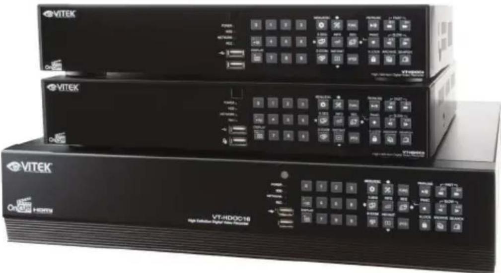
Three black VITEK Ethernet devices with control panels and indicator lights, no visible text or symbols on the device surfaces.VT-HDOCE Series
On Cue Series 4, 8, and 16 Channel Real Time 1080p EX-SDI Digital Video Recorders
• 4, 8 OR 16 CH EX-SDI / Analog Inputs (hybrid) with Full 1080p Camera Support
- Now Supporting Cable distance of up to 1000' using RG59!*
- Hybrid Operation over COAX for HD-SDI, 960H, and D1 Cameras
- Simple plug and play, point-to-point connection from camera to DVR
• Real Time Recording on all channels at 1080p (VT-HDOC4E: 120fps), (VT-HDOC8E: 240fps), (VT-HDOC16E: 480fps)
• HDMI, VGA, and Spot BNC Outputs
- Up to 5 Internal SATA2/SATA3 HDD Slots supporting up to 20TB (5 x 4TB HDD) using Advanced HDD Format
- External SATA Port (eSATA) Supporting up to 5x External via eSATA
- Pentaplex Operation (Playback, Recording, Backup, Network)
- Alarm In/Out
• Per channel Image Adjustment
• 4 Channel Audio In
• 32 x 24 Motion Detection Grid
- Multi channel Spot output
- Panorama (Thumbnail) Search
- Remote Viewing via CMS Software, Internet Explorer, and Mobile Phones (iOS/Android), Mac OSX App
• Linear digital zoom for live and playback
- Up to 7 Simultaneous Network/Remote Connections
• 256 Camera Remote Viewing via CMS Software
• RS485 Communication port
LIMITED PRODUCT WARRANTY
VITEK products carry a three (3) year limited warranty. VITEK warrants to the purchaser that products manufactured by VITEK are free of any rightful claim of infringement or the like, and when used in the manner intended, will be free of defects in materials and workmanship for a period of three (3) years, or as otherwise stated above, from the date of purchase by the end user. This warranty is nontransferable and extends only to the original buyer or end user customer of a VITEK Authorized Reseller.
The product must have been used only for its intended purpose, and not been subjected to damage by misuse, willful or accidental damage, caused by excessive voltage or lightning.
The product must not have been tampered with in any way or the guarantee will be considered null and void.
This guarantee does not affect your statutory rights.
Contact your local VITEK Reseller should servicing become necessary.
VITEK makes no warranty or guarantee whatsoever with respect to products sold or purchased through unauthorized sales channels. Warranty support is available only if product is purchased through a VITEK Authorized Reseller.