VTC-TTB36R2V - Security Camera Vitek - Free user manual and instructions
Find the device manual for free VTC-TTB36R2V Vitek in PDF.

User questions about VTC-TTB36R2V Vitek
0 question about this device. Answer the ones you know or ask your own.
Ask a new question about this device
Download the instructions for your Security Camera in PDF format for free! Find your manual VTC-TTB36R2V - Vitek and take your electronic device back in hand. On this page are published all the documents necessary for the use of your device. VTC-TTB36R2V by Vitek.
USER MANUAL VTC-TTB36R2V Vitek
2.1 Megapixel Indoor/Outdoor HD-TVI IR Bullet Cameras

natural_image
Exterior view of two white surveillance cameras with metallic caps and mounting flanges (no visible text or symbols)FEATURES
• 1/3" 2.1 Megapixel Progressive Scan CMOS image sensor
• 2.1 MegaPixel Video Transmission over COAX cable at distances of up to 1500' using HD-TVI Technology*
• 2.8\~12mm Varifocal Lens (VTC-TTB42R2V) / 3.6mm Fixed Iris Lens (VTC-TTB36R2F)
• 42 Infrared LED's with 150' IR Range (VTC-TTB42R2V) / 36 Infrared LED's with 120' IR Range (VTC-TTB36R2F)
• Digital Wide Dynamic Range (D-WDR)
• True Mechanical Day/Night function by ICR
• 3D-DNR Noise Reduction
• IP66 Weather Resistance
• 12VDC Operation
Safety Precaution
- To prevent electrical shock and risk of fire hazards, do not expose this unit to rain or moisture and only use specified power source..
text_image
CAUTION RISK OF ELECTRIC SHOCK . DO NOT OPEN CAUTION: TO REDUCE THE RISK OF ELECTICAL SHOCK, DO NOT REMOVE COVER (OR BACK). NO USER SERVICEABLE PARTS INSIDE. REFER SERVICING TO QUALIFIED SERVICE PERSONNEL
The symbol is intended to alert the user to the presence of uninsulated "dangerous voltage" within the product's enclosure that may be of sufficient magnitude to constitute a risk of electrical shock.
The symbol is intended to alert the user to the presence of important operating and maintenance (servicing) instructions in the literature accompanying the unit.
- Warning :
This equipment has been tested and found to comply with the limits for a Class A digital device, pursuant to part 15 of the FCC Rules. These limits are designed to provide reasonable protection against harmful interference when the equipment is operated in a commercial environment. This equipment generates, uses, and can radiate radio frequency energy and, if not installed and used in accordance with the instruction manual, may cause harmful interference to radio communications. Operation of this equipment in a residential area is likely to cause harmful interference in which case the user will be required to correct the interference at their own expense.
- Caution :
Any changes or modifications in construction of this device which are not expressly approved by the party responsible for compliance could void the user's authority to operate the equipment.
Main power quality should be that of a typical commercial environment. If the user of the model requires continued operation during power interruptions, it is recommended that the device be powered from an uninterruptible power supply (UPS).
Components and Accessories
| Camera | 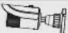 | Screws |  |
| User Manual |  | Drill Template |  |
Overview
This camera series supports both fixed and varifocal lenses. Please note that the zoom and focus features mentioned below are only available on the varifocal lens version.
text_image
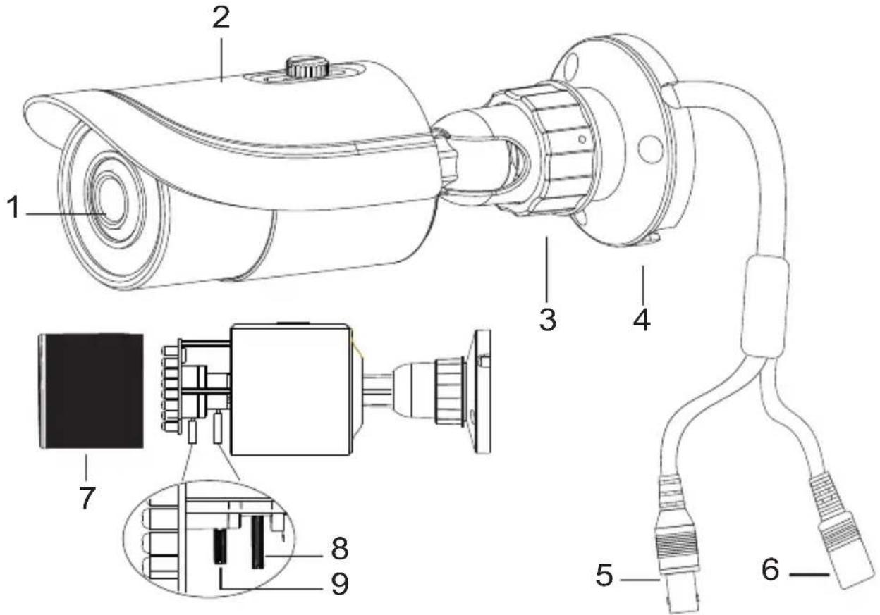
Technical diagram of a surveillance camera with labeled components and internal wiring details| 1 | Lens | 6 | Power Cable |
| 2 | Sun Shield | 7 | Lens Cover |
| 3 | Mount Lock | 8 | Zoom* |
| 4 | Mount Base | 9 | Focus* |
| 5 | Video Cable |
*Optional
Video Connection
Connect the video connector to a BNC patch cable.
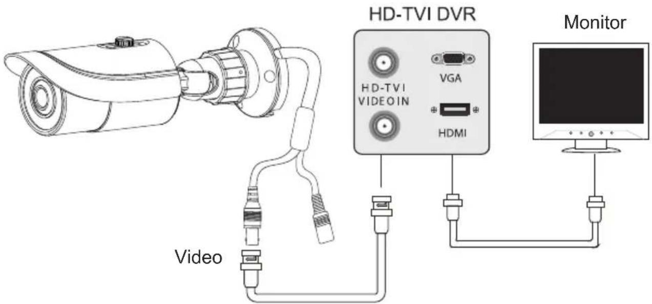
text_image
HD-TVI DVR VGA HDMI Monitor VideoPower Connection
Connect the power connector to a 12 VDC power adaptor.

text_image
Power 12VDCInstallation
Before start, please make sure that the wall or ceiling is strong enough to withstand 3 times the weight of the camera. The mounting steps are as follows:
- Attach the drill template to the place where you want to install the camera, then drill 3 screw holes and 1 cable hole (if you want to route the cables through the mounting base) according to the drill template

natural_image
Simple circular diagram with a central crosshair and four corner symbols (no text or labels)- Route the cables and connect the power & video cables, then secure the mounting base to the ceiling or wall with screws.
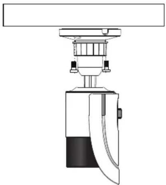
natural_image
Technical line drawing of a mechanical device with no visible text or symbolsCeiling Mounted

natural_image
Technical line drawing of a mechanical device with no visible text or symbolsWall Mounted
Installation
- Loosen the mount lock to adjust the Pan and Tilt of the camera, then tighten the mount lock to secure the viewing angle adjustments.

text_image
360° Pan 90° Tilt- To adjust the lens, start by removing the Lens Cover, then adjust the Focus and Zoom levers to achieve a clear image. Replace the Lens Cover. (if your camera is Fixed lens, please skip this step)
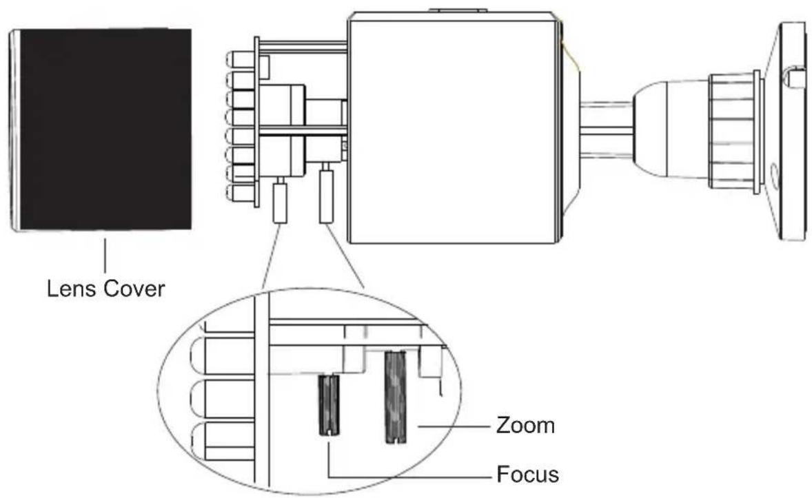
text_image
Lens Cover Zoom Focus- Carefully remove the protective film from the lens to complete the installation.
Detailed Specifications VTC-TTB42R2F VTC-TTB36R2V
| Image Sensor | 1/3" CMOS (AR0330 + NVR2421 + TP2801) | |
| Video Compression | Standard H.264 | |
| Resolution | 1080P (2 MegaPixel) | |
| Effective Pixels | 1920(H) x 1080(V) | |
| Signal System | PAL/NTSC | |
| Synchronization | Internal | |
| Lens | 3.6mm Fixed | 2.8~12mm (Vari-Focal) |
| S/R Ratio | >52dB (AGC OFF) | |
| Auto Gain Control | OFF ~44.8dB | |
| Min Illumination | O Lux (LED ON) | |
| IR LEDs | 42 | 36 |
| IR Distance | 150' | 120' |
| Color-B/W Auto Switch | Yes | |
| Electronic Shutter | 1/50s~ 1/67500s | |
| White Balance | AWB | |
| WB Range | 2300~9600K | |
| ICR | Yes | |
| BLC | Yes | |
| WDR | Digital WDR | |
| Transmission Distance | Up to 1500' (Depending on cable characteristics & integrity) | |
| Noise Reduction | Yes | |
| Video Output | BNC × 1 | |
| Weather Resistance | IP66 | |
| Power Supply | DC 12V (±10%) | |
| working Environment | -4~122 / 10%~90% Humidity | |
| Weight | 20.81 oz. / 1.30 lbs. / 590g | 21.16 oz. / 1.32 lbs. / 600g |
| Dimensions | 3.43 x 8.62" (87mm x 219mm) Dia x L | 3.43 x 8.62" (87mm x 219mm) Dia x L |
LIMITED PRODUCT WARRANTY
VITEK products carry a three (3) year limited warranty. VITEK warrants to the purchaser that products manufactured by VITEK are free of any rightful claim of infringement or the like, and when used in the manner intended, will be free of defects in materials and workmanship for a period of three (3) years, or as otherwise stated above, from the date of purchase by the end user. This warranty is nontransferable and extends only to the original buyer or end user customer of a VITEK Authorized Reseller.
The product must have been used only for its intended purpose, and not been subjected to damage by misuse, willful or accidental damage, caused by excessive voltage or lightning.
The product must not have been tampered with in any way or the guarantee will be considered null and void.
This guarantee does not affect your statutory rights.
Contact your local VITEK Reseller should servicing become necessary.
VITEK makes no warranty or guarantee whatsoever with respect to products sold or purchased through unauthorized sales channels. Warranty support is available only if product is purchased through a VITEK Authorized Reseller.