Pro 3 SE - Synthesizer Dave Smith - Free user manual and instructions
Find the device manual for free Pro 3 SE Dave Smith in PDF.

User questions about Pro 3 SE Dave Smith
0 question about this device. Answer the ones you know or ask your own.
Ask a new question about this device
Download the instructions for your Synthesizer in PDF format for free! Find your manual Pro 3 SE - Dave Smith and take your electronic device back in hand. On this page are published all the documents necessary for the use of your device. Pro 3 SE by Dave Smith.
USER MANUAL Pro 3 SE Dave Smith
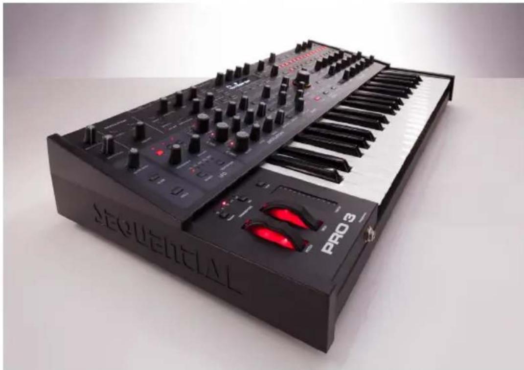
Multi-filter Mono/Paraphonic Synthesizer
natural_image
Black and white electronic instrument with black keys and red LED display, labeled 'Sequential' and 'PRO 3' (no readable text beyond branding)SEQUENTIAL®
PRO 3
User's Guide
Version 1.2
Feb, 2021
Sequential LLC
1527 Stockton Street, 3rd Floor
San Francisco, CA 94133
USA
©2020 Sequential LLC
www.sequential.com
This device complies with Part 15 of the FCC Rules. Operation is subject to the following two conditions: (1) This device may not cause harmful interference and (2) this device must accept any interference received, including interference that may cause undesired operation.
This Class B digital apparatus meets all requirements of the Canadian Interference-Causing Equipment Regulations.
For pluggable equipment, the socket-outlet shall be installed near the equipment and shall be easily accessible.
For Technical Support, email: ____ support@sequential.com
CALIFORNIA PROP 65 WARNING
This product may expose you to chemicals including BPA, which is known to the State of California to cause cancer and birth defects or other reproductive harm. Though independent laboratory testing has certified that our products are several orders of magnitude below safe limits, it is our responsibility to alert you to this fact and direct you to: https://www.p65warnings.ca.gov for more information.
Table of Contents
A Few Words of Thanks .... xi
Chapter 1: Getting Started .... 1
Rear Panel Connections 2
Using USB 4
Setting Up the Pro 3....5
Using the Main Display 6
Sound Banks....7
Selecting Programs 7
Editing Programs 8
Comparing an Edited Program to its Original State 8
Creating a Program from Scratch....9
Saving a Program.... 10
Canceling Save 11
Comparing Before You Save 11
Using Paraphonic Mode....12
Exploring the Pro 3 in Greater Depth....13
Chapter 2: Pro 3 Controls....14
Oscillators.... 15
Exploring Oscillator 3 17
Oscillator Parameters (Front Panel).... 18
Additional Oscillator Parameters (Display Menus)....19
TAB 1 - Osc Tuning 19
TAB 2 Osc Shape....20
TAB 3 - Osc Level 20
Auxiliary Envelopes 39
Auxiliary Envelope Parameters (Front Panel) 40
Additional Auxiliary Envelope Parameters (Display Menus)....41
TAB 1 - Aux 1 Destination ..... 41
TAB 3 - Aux 1 Env Amount....41
Low Frequency Oscillators 42
LFO Parameters (Front Panel) 43
Additional LFO Parameters (Display Menus)....44
TAB 1 - LFO Shape 44
TAB 2 - LFO Control....45
TAB 3 - LFO Dest....46
Modulation 46
Modulation Parameters (Front Panel) 48
Additional Mod Matrix Parameters (Display Menu) 48
Modulation Examples....48
Effects 50
Effects Parameters (Front Panel)....52
Arpeggiator....54
Arpeggiator "Momentary Sustain" Mode 56
MIDI Note Output from the Arpeggiator 57
Arpeggiator Parameters (Display Menus) 58
Clock Parameters 59
Sequencer....60
Normal, Gated, and Trigger Modes 60
Programming the Sequencer 62
Recording Phrases/Sequences A,B,C, or D. 63
Sequencing Parameter Changes in Real-Time 64
Copying a Sequence from One Track to Another. 65
Copying and Pasting an Entire Sequence 65
Muting a Sequence Track. 66
Creating An Extended Sequence 66
Paraphonic Sequencing 67
Adding Rests, Ties, and Velocity 68
Editing Duration 72
Adding Ratcheting 72
Editing Other Elements of a Sequence 73
Setting or Changing the Destination of a Track 74
Recording Additional Sequencer Tracks for Modulation. 75
Using Slew 76
Turning off the Sequencer's "Notes" Track 76
Sequencer Parameters (Front Panel) 77
Additional Sequencer Parameters (Display Menus)....78
Cue Program....79
Tuned Feedback 80
Feedback Parameters 81
Master Volume/Program Volume....82
Transpose 83
Hold 83
Glide....83
Glide Modes 84
Pitch and Mod Wheels 86
Pitch Wheel 86
Modulation Wheel....87
Touch slider 88
Adding Aftertouch 89
Distortion....90
Play List....91
Miscellaneous Parameters 93
Key Modes Tab. 93
Gate Source....94
Scale 94
Glide Tab 95
Pitch Wheel Tab 95
Global Settings 96
Chapter 3: Programming the Pro 3....104
Synthesis 101: Synth Bass .... 104
Creating Synth Brass.... 107
Turning Synth Brass into a Paraphonic String Pad 108
Creating a Hard-Sync Lead 110
A Final Word....111
Chapter 4: Using the Pro 3 with External Devices .....112
Processing External Audio 112
Filtering External Audio Using the Envelope Follower ..... 113
Syncing the Sequencer with an External MIDI Device.... 115
Using Pro 3's CV Outs to Control a Modular Synth . . . . . . . . . . . . . . . . . . . . . . 116
More About Pro 3's CV Outputs....117
Appendix A: Modulation Sources ..... 119
Appendix B: Modulation Destinations....120
Appendix C: Troubleshooting and Support ..... 122
Troubleshooting 122
Resetting the Global Parameters....124
Contacting Technical Support. 124
Warranty Repair 125
Appendix D: Calibrating the Pro 3....126
Calibrating the VCOs and Filters 126
Calibrating the Pitch and Mod Wheels .....126
Resetting the Global Parameters....126
Importing Programs and Banks 128
Appendix E: Alternative Tunings ..... 130
Appendix F: MIDI Implementation ..... 134
MIDI Messages 136
NRPN Messages 140
Control NRPN Data 147
SysEx Messages 147
Packed Data Format 150
THE SEQUENTIAL CREW
Art Arellano, Gerry Bassermann, Fabien Cesari, Bob Coover, Carson Day, Chris Hector, Tony Karavidas, Mark Kono, Justin Labrecque, Andy Lambert, Michelle Marshall, Andrew McGowan, Joanne McGowan, Julio Ortiz, Denise Smith, Tracy Wadley, and Mark Wilcox.
THE PRO 3 SOUND DESIGN TEAM
Rory Dow, Peter Dyer, GLASYS, Mike Hiegemann, Tim Koon, Tobias Menguser, Drew Neumann, Bob Oxley, Francis Preve, Lorenz Rhode, Robert Rich, Matia Simovich, Huston Singletary, James Terris, Mitch Thomas, and Taiho Yamada.
Special thanks to Kurt Kurasaki, Drew Neumann, and Robert Rich for wavetables!
A Few Words of Thanks
Thank you for purchasing the Pro 3, our latest effort to make the world's greatest monosynth. That's a bold statement, but it's true. Our biggest pleasure here at Sequential is trying to outdo ourselves with each new instrument.
In many ways the Pro 3 is the evolution of a concept that started with the classic Sequential Circuits Pro-One — pack as much power as possible into a compact footprint and make it sound awesome. In this case, that power comes in threes: three oscillators, three filters, three LFOs, plus our most powerful sequencer yet. And there’s plenty of modulation; over thirty-two slots worth, in fact.
Our formula seems to have worked. The Pro 3 doesn't just sound good, it sounds amazing. We love this synth and hope you will, too.
So stop reading and starting playing!
Cheers,
DAVE SMITH
Chapter 1: Getting Started
The Pro 3 is a hybrid synthesizer in the best sense of the word. It combines the warmth and punch of two analog, voltage-controlled oscillators and three types of classic analog filters with the versatility of a third, digital wavetable oscillator and an array of digital effects.
This blend of technologies gives you an instrument that's sonically satisfying to play, but also has power and flexibility rivaling modular systems through its extensive modulation capabilities and four control voltage ins and outs.
This chapter of your user's guide provides an overview of essential tasks such as how to make basic audio connections and how to edit and save sounds. Later chapters explain each of the parameters of the Pro 3, as well as how to program sounds and how to use the GLOBAL menu to manage its overall behavior.
We've designed the Pro 3 to be as easy to use as possible. Its essential controls are within easy reach on its front panel, so don't hesitate to dive in and start turning knobs and pressing buttons. Then, when you're ready, dig into this user's guide to explore the deeper parts of the synth.

text_image
MOBULATION EFFECTS PROVINC PRINCE SMALL MASCAL PUMBER PUMBER PUMBER PUMBER PUMBER PUMBER PUMBER PUMBER PUMBER PUMBER PUMBER PUMBER PUMBER PUMBER PUMBER PUMBER PUMBER PUMBER PUMBER PUMBER PUMBER PUMBER PUMBER PUMBER PUMBER PUMPER PUMPER PUMPER PUMPER PUMPER PUMPER PUMPER PUMPER PUMPER PUMPER PUMPER PUMPER PUMPER PUMPER PUMPER PUMPER PUMPER PUMPER PUMPER PUMPER PUMPER PUMPER PUMPER PUMPER PUMPER PUMPMER PUMPMER PUMPMER PUMPMER PUMPMER PUMPMER PUMPMER PUMPMER PUMPMER PUMPMER PUMPMER PUMPMER PUMPMER PUMPMER PUMPMER PUMPMER PUMPMER PUMPMER PUMPMER PUMPMER PUMPMEMER PUMPMEMER PUMPMEMER PUMPMEMER PUMPMEMER PUMPMEMER PUMPMEMER PUMPMEMER PUMPMEMER PUMPMEMER PUMPMEMER PUMPMEMER PUMPMEMER PUMPMEMER PUMPMEMER PUMPMEMER PUMPMEMER PULFAMMFMFMFMFMFMFMFMFMFMFMFMFMFMFMFMFMFMFMFMFMFMFMFMFMFMFMFMFMFMFMFMFMFMFMFMFMFMFMFMFMFMFMFMFMFMFMFMFMFMFMFMFMFMFMFMFMFMFMFMFMFMFMFMFMFMFMFMFMFMFMFMFMFMFMFMFMFMFMFMFMFMFMFMFMFMFMFMFMFMFMFMFM FM FM FM FM FM FM FM FM FM FM FM FM FM FM FM FM FM FM FM FM FM FM FM FM FM FM FM FM FM FM FM FM FM FM FM FM FM FM FM FM FM FM FM FM FM FM FM FM FM FM FM FM FM FM FM FM FM FM FM FM FM FM FM FM FM FM FM FM FM FM FM FM FM FM FM FM FM FM FM FM FM FM FM FM FM FM FM FM FM FM FM FM FM FM FM FM FM FM FM FM FLMFAMMFMFMFMFMFMFMFMFMFMFMFMFMFMFMFMFMFMFMFMFMFMFMFMFMFMFMFMFMFMFMFMFMFMFMFMFMFMFMFMFMFMFMFMFMFMFMFMFMFMFMFMFMFMFMFAMMFPAMMFPAMMFPAMMFPAMMFPAMMFPAMMFPAMMFPAMMFPAMMFPAMMFPAMMFPAMMFPAMMFPAMMFPAMMFPAMMFPAMMFPAMMFPAMMFPAMMFPAMMFPAMMFPAMMFPAMMFPAMMFPAMMFPAMMFPAMMFPAMMFPAMMFPAMMFPAMMFPAMMFPA M M M M M M M M M M M M M M M M M M M M M M M M M M M M M M M M M M M M M M M M M M M M M M M M M M M M M M M M M M M M M M M M M M M M M M M M M M M M M M M M M M M M M M M M M M M M M M M M M M M M FLMFAMMFPAMMFPAMMFPAMMFPAMMFPAMMFPAMMFPAMMFPAMMFPAMMFPAMMFPAMMFPAMMFPAMMFPAMMFPAMMFPAMMFPAMMFPAMMFPAMMFPAMMFPAMMFPAMMFPAMMFPAMMFPAMMFPAMMFPAMMFPAMMFPAMMFPAMMFPAMMFPAMMPPFAMMFPAMMFPAMMFPAMMFPAMMFPAMMFPAMMFPAMMFPAMMFPAMMFPAMMFPAMMFPAMMFPAMMFPAMMFPAMMFPAMMFPAMMFPAMMFPAMMFPAMMFPAMMFPAMMFPAMMFPAMMFPAMMFPAMMFPAMMFPAMMFPAMMFPAMMFPAMMFPAMMFCFAMMFPAMMFPAMMFPAMMFPAMMFPAMMFPAMMFPAMMFPAMMFPAMMFPAMMFPAMMFPAMMFPAMMFPAMMFPAMMFPAMMFPAMMFPAMMFPAMMFPAMMFPAMMFPAMMFPAMMFPAMMFPAMMFPAMMFPAMMFPAMMFPAMMFPAMMFPAMMFPAMMFGFAMNFGFANFGFANFGFANFGFANFGFANFGFANFGFANFGFANFGFANFGFANFGFANFGFANFGFANFGFANFGFANFGFANFGFANFGFANFGFANFGFANFGFANFGFANFGFANFGFANFGFANFGFANFGFANFGFANFGFANFGFANFGFANFGFANFGFANFGFANCGFANCGFANCGFANCGFANCGFANCGFANCGFANCGFANCGFANCGFANCGFANCGFANCGFANCGFANCGFANCGFANCGFANCGFANCGFANCGFANCGFANCGFANCGFANCGFANCGFANCGFANCGFANCGFANCGFANCGFANCGFANCGFANCGFANCGCFLNNGGNDGNDGNDGNDGNDGNDGNDGNDGNDGNDGNDGNDGNDGNDGNDGNDGNDGNDGNDGNDGNDGNDGNDGNDGNDGNDGNDGNDGNDGNDGNDGNDGNDGNDGNDGNDGNDGNDGNDGNDGNDGNDGNDGNDGNDGNDGNDGNDGNDGNDGNCNNGDNGDNGDNGDNGDNGDNGDNGDNGDNGDNGDNGDNGDNGDNGDNGDNGDNGDNGDNGDNGDNGDNGDNGDNGDNGDNGDNGDNGDNGDNGDNGDNGDNGDNGDNGDNGDNGDNGDNGDNGDNGDNGDNGDNGDNGDNGDNGDNGDNGDNGTNNNGDNGTNNNGTNNNGTNNNGTNNNGTNNNGTNNNGTNNNGTNNNGTNNNGTNNNGTNNNGTNNNGTNNNGTNNNGTNNNGTNNNGTNNNGTNNNGTNNNGTNNNGTNNNGTNNNGTNNNGTNNNGTNNNGTNNNGTNNNGTNNNGTNNNGTNNNGTNNNGTNNNGTNNNGTNNNQTTNQTTNQTTNQTTNQTTNQTTNQTTNQTTNQTTNQTTNQTTNQTTNQTTNQTTNQTTNQTTNQTTNQTTNQTTNQTTNQTTNQTTNQTTNQTTNQTTNQTTNQTTNQTTNQTTNQTTNQTTNQTTNQTTNQTT NQTTNQTTNQTTNQTTNQTTNQTTNQTTNQTTNQTTNQTTNQTTNQTTNQTTNQTTNQTTNQTTNQTTNQTTNQTTNQTTNQTTNQTTNQTTNQTTNQTTNQTTNQTTNQTTNQTTNQTTNQTTNQTTNQTTN QCT N QCT N QCT N QCT N QCT N QCT N QCT N QCT N QCT N QCT N QCT N QCT N QCT N QCT N QCT N QCT N QCT N QCT N QCT N QCT N QCT N QCT N QCT N QCT N QCT N QCT N QCT N QCT N QCT N QCT N QCT N QCT N QCT N QCT NQCT N QCT N QCT N QCT N QCT N QCT N QCT N QCT N QCT N QCT N QCT N QCT N QCT N QCT N QCT N QCT N QCT N QCT N QCT N QCT N QCT N QCT N QCT N QCT N QCT N QCT N QCT N QCT N QCT N QCT N QCT N QCT N QCT N QGT N QGT N QGT N QGT N QGT N QGT N QGT N QGT N QGT N QGT N QGT N QGT N QGT N QGT N QGT N QGT N QGT N QGT N QGT N QGT N QGT N QGT N QGT N QGT N QGT N QGT N QGT N QGT N QGT N QGT N QGT N QGT N QGT N QGT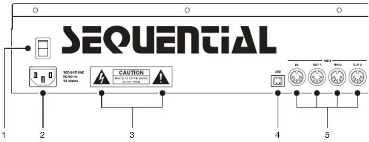
text_image
SEQUENTIAL 100-240 VAC 50-80 Hz 12 Watts CAUTION RISK OF ELECTRIC SWITCH DO NOT OPEN USB IN OUT 1 MDI THRU OUT 2 4 5Rear Panel Connections
The rear panel of the Pro 3 has connectors for power, USB, MIDI, audio, and pedals.
-
Power On/Off—This rocker switch controls power on and off to the Pro 3.
-
AC Power Connector—Accepts a standard, grounded IEC power cord. Operates over a range of 100 to 240 volts, 50 to 60Hz , and 15W.
-
Electric Shock Hazard Warning—These symbols warn that you risk electrical shock if you open the Pro 3 enclosure. Please do not open.
-
USB—For bidirectional MIDI communication with a computer. The Pro 3 is a Class Compliant USB device and does not require additional drivers when used with Mac OS or Windows. See “Using USB” on page 4 for more information.
-
MIDI In, Out 1, Thru, Out 2—Standard 5-pin MIDI DIN connectors for communicating with MIDI-equipped devices.
-
Footswitch—Accepts a momentary, normally open or normally closed footswitch to control sustain or to latch the Arpeggiator on when keys are held. Alternatively, an audio signal connected to the AUDIO IN jack can be used to either control Sequencer/Arpeggiator playback, or to gate the filter and amplifier envelopes while notes are held. Audio signals used to drive the Arpeggiator/Sequencer should not exceed 5 volts peak-to-peak.

text_image
PRO 3 FT/SATCH PEDAL 1 2 3 4 1 2 3 4 GATE OUT AUDIO IN AUDIO OUT LEFT 6789101112-
Pedal—Accepts a standard expression pedal that has a variable resistor on a TRS (tip-ring-sleeve) 14 inch phone plug. Once connected, you can use the modulation matrix to route the pedal to control a variety of things such as volume or filter cutoff frequency to add expressiveness to live performance.
-
Control Voltage Ins 1-4—Standard 3.5 mm connectors. These jacks accept a +/-5V signal for interfacing with modular synthesizers. They can be configured for 1-volt-per-octave operation for gear that recognize that standard.
-
Control Voltage Outs 1-4—Standard 3.5 mm connectors. These jacks output a +/-5V signal for interfacing with modular synthesizers. They can be configured for 1-volt-per-octave operation for gear that recognize that standard.
-
Gate Out—Standard 3.5 mm connector. This jack outputs a 10-volt on/off signal to switch a note on/off in external Sequencers and other devices that support this type of connectivity.
-
Audio In—Unbalanced, 14 inch audio input. The Pro 3 accepts external audio signals for processing through this connector. Input level can be adjusted using the EXT AUDIO knob in the Mixer section.
-
Audio Outputs—Unbalanced, 14 inch audio outputs. The Pro 3 sounds great in stereo, but can be switched to mono if needed. See “Global Settings” on page 96.
-
Headphones (on front) — 14 inch stereo headphone jack. Headphone volume is controlled by the MASTER VOLUME knob on the front panel.
Using USB
The Pro 3's USB 2.0 port enables bidirectional MIDI communication with a computer. A MIDI interface and MIDI cables are not necessary, just a USB cable. The Pro 3 is a Class Compliant USB device. That means it does not require any additional drivers to be installed to communicate with a Mac or Windows computer. The Pro 3 transmits and receives MIDI data via USB, but does not transmit audio.

MIDI In and USB should not be used at the same time, as overlapping
messages from different sources may cause the Pro 3 to respond unpredictably. MIDI Out and USB can be used at the same time and transmit the same data.
Under Mac OS, “Pro 3” will appear as a MIDI port when connected via USB and can be configured using the Mac’s Audio MIDI Setup utility (typically found in Applications/Utilities).
Under Windows, the first time the Pro 3 is connected via USB, the “Found new hardware” alert appears and it is automatically installed as “Pro 3.”
In Windows, if you unplug the USB cable and plug it back in while a program has the Pro 3 port open, you may have to resync. That usually means going to the Pro 3 Keyboard Properties — in the Windows Device Manager under “Sound, video, and game controllers” — and clicking OK. If Pro 3 is no longer listed in the Device Manager, turn off the Pro 3 then turn it back on again while it is connected via USB. It should be detected on power up.
Setting Up the Pro 3
Here's how to get your Pro 3 up and running:
Getting Started:
- Plug the power cable into the AC power connector on the back panel of the Pro 3.
- If you have an expression pedal, connect it to the PEDAL jack on the back of the Pro 3. If you have a sustain pedal, connect it to the FOOT-SWITCH jack.
- Turn on the Pro 3.
- Connect the LEFT and RIGHT audio outputs on the back of the Pro 3 to your amp/mixer/powered speakers using unbalanced, 14 inch audio cables. These are the main stereo outputs for the synth.
- Turn up the volume on your amp/mixer/powered speakers.
- Turn up the volume on the Pro 3.
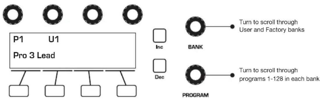
- Use the BANK and PROGRAM knobs to scroll through the factory sounds. You can also use Soft Knob 1 and Soft Knob 2 as well as INC and DEC buttons to scroll through the sounds in the currently selected bank.
flowchart
graph TD
    A["P1 U1\nPro 3 Lead"] --> B["Inc"]
    A --> C["Dec"]
    D["BANK"] --> E["Turn to scroll through User and Factory banks"]
    F["PROGRAM"] --> G["Turn to scroll through programs 1-128 in each bank"]
Bank and Program controls

Each of the factory presets has interesting and useful modulation functions programmed into the touch slider and the mod wheel. While you're trying out the factory sounds, play with these performance controls and listen how the sound changes. Each preset also has a pre-programmed sequence. To hear it, press the PLAY button in the SEQ section.
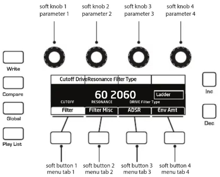
Using the Main Display
The most frequently used controls on the Pro 3 are on its front panel. But there are many additional controls (as well as numeric display of values) visible in its main display.
For example, adjusting a knob or switch in the OSCILLATORS section reveals the tuning, shape, and level menus in the display. The display also reveals parameters not found on the front panel such as OSC SLOP and WAVE RESET (in Tab 2). You can select and edit these additional parameters using the four Soft Knobs and Soft Buttons located above and below the display.
The Soft Knobs are for dialing in values. The Soft Buttons select between various menu tabs.

flowchart
graph TD
    A["soft knob 1\nparameter 1"] --> B["Filter"]
    C["soft knob 2\nparameter 2"] --> D["Filter Misc"]
    E["soft knob 3\nparameter 3"] --> F["ADSR"]
    G["soft knob 4\nparameter 4"] --> H["Env Amt"]
    I["Write"] --> J["60 2060"]
    K["Compare"] --> L["60 2060"]
    M["Global"] --> N["60 2060"]
    O["Play List"] --> P["60 2060"]
    Q["Soft Button 1\nmenu tab 1"] --> R["Filter Misc"]
    S["Soft Button 2\nmenu tab 2"] --> T["Filter Misc"]
    U["Soft Button 3\nmenu tab 3"] --> V["Filter Misc"]
    W["Soft Button 4\nmenu tab 4"] --> X["Filter Misc"]
    Y["Ladder"] --> Z["60 2060"]
    AA["Inc"] --> AB["60 2060"]
    AC["Dec"] --> AD["60 2060"]
The Main Display
Sound Banks
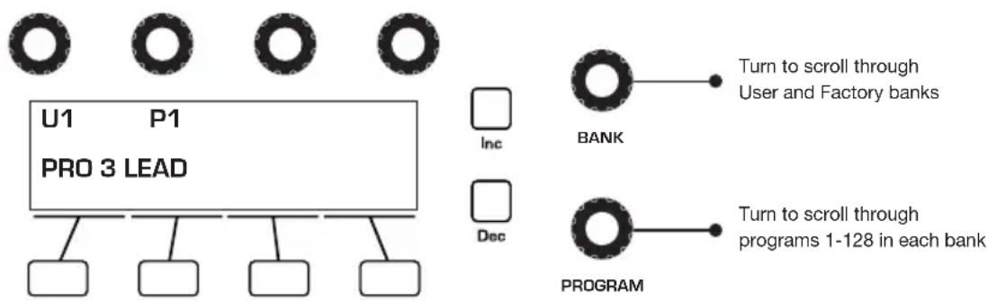
The Pro 3 contains a total of 1024 programs. Banks U1-U4 are user banks that can be overwritten. Banks F1-F4 are factory banks that are permanent. As shipped, user banks U1-U4 are identical to permanent factory banks F1-F4. Each bank has 128 programs (multiplied by 4 banks = 512 programs each). You can edit the programs of either bank, but you can only save them to user banks U1-U4.
Banks of non-rewritable, permanent sounds are included so that they are always available, to be used as is, or as templates for new sounds of your own. It’s easy to design a new sound by tweaking an existing one.
flowchart
graph TD
    A["U1"] --> B["PRO 3 LEAD"]
    C["P1"] --> B
    D["Inc"] --> B
    E["Dec"] --> B
    F["BANK"] --> G["Turn to scroll through User and Factory banks"]
    H["PROGRAM"] --> I["Turn to scroll through programs 1-128 in each bank"]
Bank and Program controls
Selecting Programs
Use the BANK and PROGRAM knobs to select and recall programs.
To choose a program:
- Turn the BANK knob to select the bank you want.
- Turn the PROGRAM knob to select a program within that bank.
Editing Programs
Because the majority of the sound-shaping controls of the Pro 3 appear on its front panel, editing an existing program is simple: turn a knob and listen to its effect. Keep turning knobs and pressing buttons. If you like what you’ve created, save the program by pressing the WRITE button twice. (See “Saving a Program” on page 10 for more options when you save.)
The rotary controls on the front panel are a mixture of rotary encoders (which have no position indicator) and potentiometers or “pots,” which have a position indicator and a finite travel range from left to right. You can choose between three different modes that determine how the synth reacts when you edit its parameters with a pot. For details, see page 98.
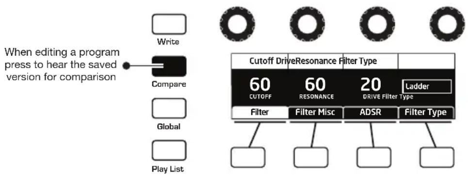
Comparing an Edited Program to its Original State
When editing a program, it's often useful to compare its edited state to its original state to evaluate your edits.
To compare an edited program to a saved version:
- Edit a program, then press the COMPARE button.
- Play the keyboard to hear the saved version of the sound.
- To disable the compare function and return to the edited sound, press the COMPARE button again to turn it off. Programs can't be written while in compare mode.
text_image
When editing a program press to hear the saved version for comparison Write Compare Global Play List Cutoff DriveResonance Filter Type 60 60 20 Ladder CUTOFF RESONANCE DRIVE Filter Type Filter Filter Misc ADSR Filter TypeCompare button
It's also useful to be able to check the value of a parameter for reference. Normally, to make a parameter value appear in the display, you have to turn the parameter's knob — which will change the parameter value. But there is a way to do this without changing the value:
To check the value of a parameter without changing it:
-
Press the show button.
-
Turn any parameter knob. The value appears in the display.
-
To return to normal operation, press the show button again to disable it.

text_image
Press the Show button and turn any knob to see its current setting without changing it. Revert Write Show Compare Misc Params Global Paraphonic Play List Cutoff DriveResonance Filter Type 60 2060 Ladder CUTOFF RESONANCE DRIVE Filter Type Filter Filter Misc ADSR Filter TypeUsing the Show button to display a parameter value
Creating a Program from Scratch
An existing program can be very useful as a jumping off point for new sounds. But it's also useful (and educational) to create a new sound from scratch. The Pro 3 makes this easy by providing a “basic preset” that you can quickly recall at any time. This preset is very simple, with a single oscillator as its basis.
To recall the basic program:
- Press the GLOBAL button.
- Use Soft Knob 1 to scroll through the commands and select BASIC PROGRAM in the display menu.
- Press soft button 1 (WRITE NOW). The current sound settings are reset to the basic program.
- Press the GLOBAL button again to return to normal operation. From here you can begin creating your own sound using the basic program as a starting point.
Chapter 3 provides a selection of simple sound design tutorials. It’s designed to give you a basic working knowledge of how to use the Pro 3 to make your own sounds. See “Chapter 3: Programming the Pro 3” on page 104.
Saving a Program
If you've created a sound that you like, you'll probably want to save it. Saving a program overwrites a previously saved program. Sound designers often save many incremental versions of a program as they continue to refine it. These intermediate versions often make good jumping off points for new sounds.
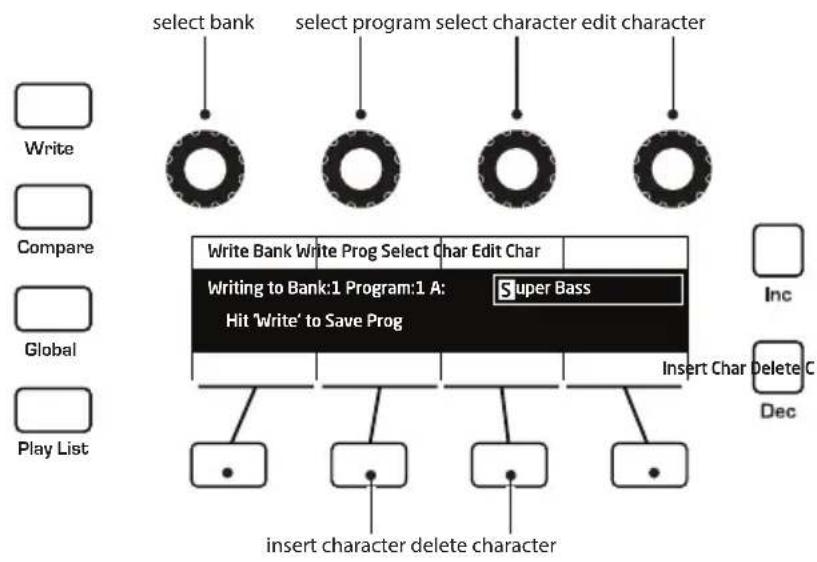
To save a program to the same preset location:
- Press the WRITE button. Its LED begins blinking.
- Enter a name for the program using the appropriate Soft Knobs and Soft Button. (See the illustration that follows for their functions.)
- Press the WRITE button again. Its LED stops blinking and the program is saved.
To save a program to a different location:
- Press the WRITE button. Its LED begins blinking.
- Turn the BANK or PROGRAM knobs (or Soft Knob 1 and Soft Knob 2) to select a new location. You can only save to banks U1-U4.
- Enter a name for the program using the appropriate Soft Knobs and Soft Buttons. (See the illustration that follows for their functions.)
Press the WRITE button again. Its LED stops blinking and the program is saved.
flowchart
graph TD
    A["select bank"] --> B["Write"]
    C["select program"] --> D["Compare"]
    E["select character edit"] --> F["Global"]
    G["select character edit"] --> H["Play List"]
    B --> I["Write Bank Write Prog Select Char Edit Char"]
    D --> J["Writing to Bank:1 Program:1 A: Super Bass Hit 'Write' to Save Prog"]
    F --> K["Insert Char Delete C"]
    H --> L["Insert character delete character"]
    I --> M["•"]
    J --> N["•"]
    K --> O["•"]
    L --> P["•"]
Saving a Program
Canceling Save
Sometimes you may want to cancel saving a program before you commit.
To cancel the save process before you commit:
- If the WRITE button LED is flashing, press the GLOBAL button. The WRITE LED stops flashing and saving is canceled. You can return to editing if you want.
Comparing Before You Save
Before saving a program to a new location, it's a good idea to listen to the program in the target location to make sure you really want to overwrite it.
To evaluate a program before you overwrite it:
-
Get ready to save by pressing the WRITE button. It starts flashing.
-
Press the COMPARE button. Its LED lights up.
-
Use the BANK and PROGRAM knobs to navigate to the sound you want to audition and play the keyboard to hear the sound in the target location.
-
If you don't want to overwrite that location, use the Bank and Program knobs to select other possible locations to audition.
-
Once you have found a location to overwrite, press the COMPARE button again to turn it off. (Programs can't be written while in compare mode.)
- The WRITE button is still flashing and ready to save. Press WRITE and the sound is saved.
- Alternatively, if you want to cancel saving and continue editing, press the GLOBAL button. Saving is canceled.

You can use the GLOBAL button to set the program that appears when you power on the Pro 3. Simply use the BANK and PROGRAM knobs to find the program you want, then press the GLOBAL button twice. That program is now the default program on start up.
Using Paraphonic Mode
The Pro 3 was designed primarily as a monophonic instrument. But we added a 3-voice paraphonic playback mode for extra performance power. In this mode, the three oscillators can be triggered independently, each with its own amplifier envelope. (However, the filter and its envelope are shared between the three oscillators.) This gives you the ability to play chords of up to 3 notes.

Make sure to select a waveshape for oscillator 3 since it's possible to set this oscillator to OFF. Each oscillator is triggered with an envelope set by the VCA shape.

text_image
Revert Write Show Compare Misc Params Global Paraphonic Play List Press the Paraphonic button to enable 3-voice paraphonic mode. Cutoff DriveResonance Filter Type 60 CUTOFF 60 RESONANCE 20 Ladder Filter Filter Misc ADSR Env AmtTo enable paraphonic playback:
- Press the PARAPHONIC button.
- Turn up the levels of all three oscillators in the MIXER.
- Play some chords.
- Adjust the Octave and oscillator waveshapes as necessary.

With clever programming you can create complex sounds that work well in paraphonic mode. Add a bit of pulse width modulation or chorused delay to create interesting string and pad sounds.
Exploring the Pro 3 in Greater Depth
Before you explore the sound creation possibilities of the Pro 3, we'd like to point you toward a few things that will help you tailor it to your needs. The better you know it, the more you'll get out of it.
First, read “Global Settings” on page 96. There are many useful settings and functions found in the Global menu that will affect the overall behavior of your Pro 3, including tuning, MIDI connections, calibration, and more. In particular, read about Pot Modes and determine which works best for you when you’re editing sounds.
Also, in “Rear Panel Connections” on page 2 read about the various connectors on the back of your Pro 3 and how you can use its various pedal, audio, MIDI, and USB inputs and outputs.
Finally, be on the lookout for tips and notes scattered throughout this manual to gain a better working knowledge of the Pro 3. We wish you many hours of musical exploration!
Chapter 2: Pro 3 Controls
This chapter explains all of the controls on the Pro 3, section by section.
As explained in Chapter 1, the most frequently used Pro 3 controls are located on its front panel, with additional controls (as well as numeric display of values) visible in its main display.
Adjusting a knob or switch in the Mixer section reveals the three oscillator level parameters and noise level parameter in the display. The display also reveals additional parameters not found on the front panel such as external input level, gate threshold, and more. You can select and edit these additional parameters using the four Soft Knobs and Soft Buttons located above and below the display.
The Soft Knobs are detented encoders for dialing in values. The Soft Buttons select between various menu tabs.
flowchart
graph TD
    A["soft knob 1\nparameter 1"] --> B["60 2060"]
    C["soft knob 2\nparameter 2"] --> B
    D["soft knob 3\nparameter 3"] --> B
    E["soft knob 4\nparameter 4"] --> B
    F["Write"] --> B
    G["Compare"] --> B
    H["Global"] --> B
    I["Play List"] --> B
    B --> J["CUTOFF"]
    B --> K["RESONANCE"]
    B --> L["DRIVE FILTER TYPE"]
    B --> M["Ladder"]
    B --> N["Filter"]
    B --> O["Filter Misc"]
    B --> P["ADSR"]
    B --> Q["Env Amt"]
    R["soft button 1\nmenu tab 1"] --> S
    T["soft button 2\nmenu tab 2"] --> S
    U["soft button 3\nmenu tab 3"] --> S
    V["soft button 4\nmenu tab 4"] --> S
The Main Display
Oscillators
Oscillators generate the raw building blocks of the Pro 3's sound by producing waveforms, each of which has its own sound character based on its harmonic content. The Pro 3 has two analog, voltage-controlled oscillators and one digital wavetable oscillator.
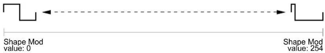
Oscillators 1 and 2 generate triangle, sawtooth, and pulse waves. You can vary the “pulse width” of these waveshapes using the SHAPE MOD parameter. This allows for a variety of different waveshapes and timbres.
text_image
Shape Mod value: 0 Shape Mod value: 254Oscillator 3, because it's digital, generates not only triangle, sawtooth, super saw, and pulse waves but also complex, wavetable-derived wave shapes.
text_image
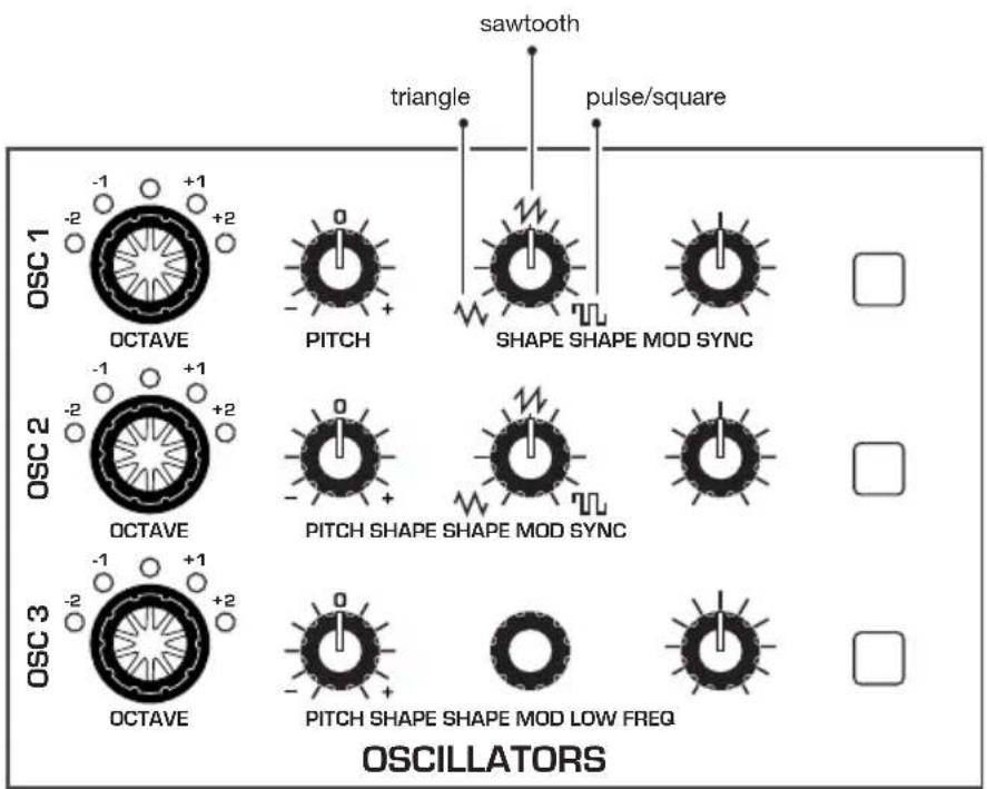
sawtooth triangle pulse/square OSC 1 OCTAVE PITCH SHAPE SHAPE MOD SYNC OSC 2 OCTAVE PITCH SHAPE SHAPE MOD SYNC OSC 3 OCTAVE PITCH SHAPE SHAPE MOD LOW FREQ OSCILLATORSThe Oscillators section
To listen to the oscillators:
- Press the GLOBAL button.
- Use Soft Knob 1 to navigate to the BASIC PROGRAM command, then press Soft Button 1 (WRITE NOW).
- In the basic program, only Oscillator 1 is audible. (The levels of Oscillators 2 and 3 are set to zero by default.)
- Hold down a note on the keyboard and in the OSCILLATORS section, turn the SHAPE knob left and right to hear the waveshape change from triangle to sawtooth to pulse. (Sawtooth is selected by default in the basic program.)
- With a specific waveshape selected, turn the SHAPE MOD knob and listen to how the timbre of the waveshape changes. Note that when using SHAPE MOD with the pulse wave, it's possible to make the pulse width so narrow that the sound "disappears."
- Be aware that on Oscillator 3, when SUPER SAW is selected as the wave-shape (refer to the display to see the name of the waveshape), SHAPE MOD controls the detuning of the Super Saw wave.
- Turn up the level of Oscillator 2 in the Mixer and experiment with setting each oscillator to a different waveshape. Experiment with the PITCH knob on the oscillators and notice how slightly detuning the oscillators in relation to each other creates movement and thickness in their combined sound. Try tuning one oscillator to a interval such as a third, a fifth, or a sixth.
- Experiment with the OCTAVE knob on the oscillators and notice how setting each oscillator to different octave influences their combined sound. This is especially true when using all three oscillators together.
- Choose one of the three filter types and rotate the filter's CUTOFF and RESONANCE knobs to see how this affects the sound of the oscillators.
- With Oscillator 1 and 2 on, press the SYNC button on Oscillator 1, and set it's OCTAVE to 5. Then rotate the PITCH knob on Oscillator 1 while you hold a note. This is the classic hard sync sound that you've probably heard before. Instead of rotating the PITCH knob by hand, you can use the modulation matrix to route an envelope to Oscillator 1 to sweep the oscillator's pitch and create this effect each time you play a note. You'll learn more about the mod matrix in "Modulation" on page 46.
Exploring Oscillator 3
Because Oscillator 3 is a digital wavetable oscillator, it generates a variety of waveshapes. In addition to the standard, static waveshapes of sine, sawtooth, super saw, and pulse waves, it provides 32 wavetables, each with 16 different waves within that table.
Once you select one of the 32 wavetables with the SHAPE knob, you can then select a wave within the wavetable using the SHAPE MOD knob. When you turn the SHAPE MOD knob, you'll hear the waveshapes morph smoothly from one to the next as the Pro 3 interpolates between them.
If you select one of the 32 wavetables, you can then select a specific static wave. Or, if you use an LFO or the modulation matrix to control SHAPE MOD, you can sweep through the selected table's 16 waves to create timbres that shift and evolve in interesting ways.
To listen to Oscillator 3:
-
Press the GLOBAL button. Use Soft Knob 1 to navigate to the BASIC PROGRAM command, then press Soft Button 1 (WRITE NOW).
-
In the basic program, only Oscillator 1 is audible. The levels of Oscillators 2 and 3 are set to zero in the Mixer by default.
-
In the MIXER section, turn down the level of Oscillator 1 and turn up the level of Oscillator 3.
-
Play and hold a note on the keyboard. In the OSCILLATORS section, turn the SHAPE knob on Oscillator 3 to select one of the 32 wavetables. The first choices are sine, sawtooth, super saw, and pulse, after that are wavetables 1-32
-
Turn the SHAPE MOD knob to select a waveshape within the currently selected wavetable. When you turn the knob, you'll hear the wave-shapes morph smoothly from one to the next.
To use an LFO to sweep through the waves in a wavetable:
-
Use the SHAPE knob on Oscillator 3 to select one of the 32 wavetables.
-
In the LFO section, press the LFO 3 button, then the DESTINATION button.
-
In the display, choose osc 3 SHAPEMOD as the destination.
-
Hold down a note on the keyboard and listen as you set the FREQUENCY and AMOUNT of LFO 3 modulation as desired. Higher FREQUENCY settings sweep through the wavetable faster. Higher AMOUNT settings sweep though a wider range of waves in the wavetable.
Oscillator Parameters (Front Panel)
Shape: Selects the waveshape generated by the oscillator. Oscillators 1 and 2 produce triangle, sawtooth, and pulse analog waveshapes. These waveshapes are continuously variable. Oscillator 3 produces triangle, sawtooth, super saw, and pulse waves, plus 32 wavetables containing 16 waves each.
Octave: Sets the base frequency of an oscillator over a 5-octave range. The global MASTER COARSE and MASTER FINE settings affect the pitch of the oscillators. See “Global Settings” on page 119 for more information.
Pitch: -700...+699—Fine tune control with a range of 7 semitones (a major 5th) up or down. The 12 o'clock position is centered.
Shape Mod: On Oscillator 1 and 2, this changes the “pulse” width of the selected waveform, which modifies its harmonic content and timbre. To generate a square wave when PULSE is selected as the waveform, set this parameter to 0. On Oscillator 3, this knob selects a waveshape within the currently selected wavetable. If SUPER SAW is selected as the waveshape, SHAPE MOD controls the thickness (detuning) of the Super Saw.

Applying waveshape modulation using an LFO or other modulation source in the mod matrix is a great way to add movement to a sound.
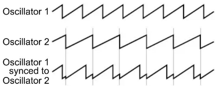
Sync: Off, On—Turns on oscillator hard sync. When an oscillator is hard synced, its wave cycle is slaved to another oscillator's wave cycle and is forced to reset each time the master oscillator's wave cycle restarts. This causes the slaved oscillator to create harmonically complex waveforms — particularly when the slave oscillator's pitch is set higher than the master oscillator's pitch. See page 110 to learn how to set up a classic oscillator hard sync sound.
text_image
Oscillator 1 Oscillator 2 Oscillator 1 synced to Oscillator 2Oscillator hard sync
Low Freq: Turns Oscillator 3 into an LFO (low frequency oscillator) so that it can be used for modulation. Since Oscillator 3 is a wavetable oscillator, the variety of waveshapes it produces is far greater than LFOs 1-3 and it can be used to create many interesting modulation effects.
Additional Oscillator Parameters (Display Menus)
Additional oscillator parameters are accessible through the menus in the main display. To see these menus, adjust any control in OSCILLATORS section of the front panel. The parameters explained below do not appear on the front panel.
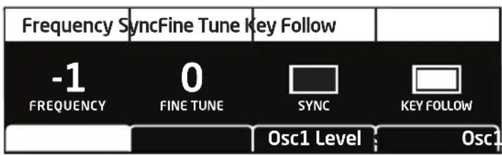
TAB 1 - Osc Tuning
text_image
Frequency SyncFine Tune Key Follow -1 FREQUENCY 0 FINE TUNE SYNC KEY FOLLOW Osc1 Level Osc1Key Follow: Off, On—When on, the oscillator tracks the keyboard or note data received via MIDI. When off, the oscillator plays at its base frequency setting, though its pitch may be affected by modulation from other sources.
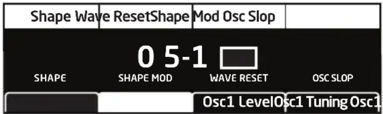
TAB 2 Osc Shape
text_image
Shape Wave ResetShape Mod Osc Slop 0 5-1 □ SHAPE SHAPE MOD WAVE RESET OSC SLOP Osc1 LevelOsc1 TuningOsc1Osc1 Shape
Wave Reset: Off, On—(In the osc1 SHAPE tab in the display) When Wave Reset is off, the Pro 3 oscillators are free running. That is, the oscillators are running whether a note is being gated on or not. When the amplifier envelope is set for a fast attack, this can cause a soft, but detectable, pop or click at the beginning of a note because the note might be gated on at a point in the wave's cycle other than a zero crossing. The first cycle to play might be truncated. For some sounds, like monophonic basses, this may actually be desirable. It adds a bit of randomness to the attack that can make it sound more organic. When WAVE RESET is on, the wave is always reset to zero (the start of its cycle) when a note is triggered.
Osc Slop: 0...127—Adds random detuning to add or enhance the natural pitch drift of the chosen oscillator. Vintage analog synthesizers all had a certain amount of natural pitch drift which added to the warmth of their sound. Smaller amounts of oscillator slop are subtle and add a more organic feel. Larger amounts create a pronounced “out of tune” effect.
TAB 3 - Osc Level

text_image
Osc 1 127 OSC 1 0 SHAPE MOD WAVE RESET OSC SLOP Osc1 Level Osc1 Tuning Osc1Osc Level: 0...127—Sets the output level for the selected oscillator. When using all three oscillators at once, especially with high levels of RESONANCE or DRIVE, it may be necessary to reduce their levels to avoid distortion (unless desired).
TAB 4 - Osc Misc
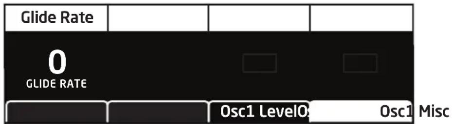
text_image
Glide Rate 0 GLIDE RATE Osc1 Level0 Osc1 MiscGlide Rate: 0...127—Sets the oscillator glide (portamento) amount.
Glide causes the pitch of a note to glide smoothly up or down from the pitch of the previously played note. It can be set independently for each oscillator. Low values are shorter/faster. The GLIDE switch must be on to hear the effect of GLIDE RATE. For a detailed explanation, see “Glide” on page 83.
Mixer
The Mixer section is where you set the levels of the various sound generators on the Pro 3. These include oscillators 1-3, the noise generator, and an external input when connected to the rear panel input of the Pro 3. You must turn up at least one of these sources in order to make sound with the Pro 3. Alternatively, when using Low-pass 1 or Low-pass 2, you can make the filter generate its own sine wave by turning up RESONANCE all the way so that it self-oscillates. The State-Variable filter doesn't self-oscillate.

Rather than limit the outputs of the Pro 3 to keep the instrument from clipping, we allow you to adjust levels at various points in its signal path. This gives you the option of "overloading" things in interesting ways, if you wish to do so. If not, try reducing the levels of the oscillators in the MIXER section, turning down the DRIVE and RESONANCE parameters in the Filter section, or the AMOUNT parameter in the Amp Envelope section.
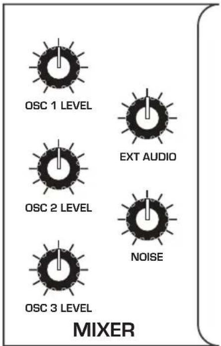
Osc 1 Level: 0...127—Sets the output level of oscillator 1.
Osc 2 Level: 0...127—Sets the output level of oscillator 2.
Osc 3 Level: 0...127—Sets the output level of oscillator 3.
Ext Audio: 0...127—Sets the output level of an external signal connected to the AUDIO IN jack on the rear panel of the Pro 3.
Noise: 0...127—Sets the output level of the noise generator.
Additional Mixer Parameters (Display Menu)
Additional Mixer parameters are accessible through the menus in the main display. To see these menus, adjust any control in MIXER section of the front panel. The parameters explained below do not appear on the front panel.
TAB 2 - Ext in
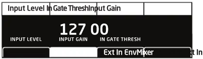
text_image
Input Level In Gate ThreshInput Gain 127 00 INPUT LEVEL INPUT GAIN IN GATE THRESH Ext In EnvMixer InInput Gain: 0...127—Boosts the input level of any signal connected to the AUDIO IN connector on the rear panel of the Pro 3. This is useful for increasing the gain of low-level output devices such as guitars.
In Gate Thresh: 0...127—Sets the threshold above which external input signals will trigger the Pro 3's. Triggering from an external audio input allows you to drive the Pro 3's Sequencer steps with guitars, drum machines and other devices.
TAB 3 - Ext in Env

flowchart
graph TD
    A["Input Attack"] --> B["0 INPUT ATTACK"]
    B --> C["0 INPUT RELEASE"]
    C --> D["Mixer"]
    C --> E["Ext In"]
    C --> F["Ext In Env"]
Input Attack: 0...15—Sets the attack speed of the envelope follower. Use this to fine tune the response of the envelope follower when triggering the Sequencer from an external device connected to the AUDIO IN jack on the rear panel of the Pro 3.
Input Release: 0...127—Sets the release speed of the envelope follower. Use this to fine tune the response of the envelope follower when triggering the Sequencer from an external device connected to the AUDIO IN jack on the rear panel of the Pro 3.
Filters
The Pro 3 has three different filters, each of which has its own unique character:
- LOW-PASS 1 - 4-POLE OTA is a 4-pole, 24 db-per-octave resonant filter based on the Sequential Prophet-6 filter. It can self-oscillate (generate a sine wave) when RESONANCE is set to its maximum.
- LOW-PASS 2 - 4-POLE LADDER is a classic 4-pole, 24 db-per-octave resonant transistor ladder filter. It can self-oscillate when RESONANCE is set to its maximum
- STATE-VARIABLE - 2-POLE OTA is a 2-pole, 12 db-per-octave filter based on the Sequential OB-6 filter. It features low-pass, band-pass, high-pass, and notch operation. The State-Variable filter cannot self-oscillate.
Another characteristic of the State-Variable filter is that increasing the amount of RESONANCE does not decrease the amount of low-frequencies (bass). On Low-pass 1 and Low-pass 2, increasing the amount of RESONANCE de-emphasizes low frequencies. The BP and STATE controls apply only to the State-Variable filter.
The differences between these filters can be subtle or dramatic, depending on their individual settings, the amount of filter resonance applied, and other factors. The function of the filters is to subtract frequencies from the sound produced by the oscillators, noise generator, and/or external audio input, thereby changing the overall harmonic content of the synth's sound. This change is varied over time using the Filter Envelope to produce more dynamic timbres.

text_image
DRIVE NOTCH LP STATE HP CUTOFF RESONANCE BP 4-Pole OTA 4-Pole Ladder 2-Pole OTA LOW-PASS 1 LOW-PASS 2 STATE-VARIABLE FILTERPress one of these buttons to select the filter type
To hear the effect of the filter:
- Recall the Basic Program by pressing the GLOBAL button and using Soft Knob 1 to navigate to the BASIC PROGRAM command, then press Soft Button 1 (WRITE NOW).
- Press the LOW-PASS 1 button to select this filter.
- Hold down a note and rotate the filter's CUTOFF knob. Notice how it cuts the high frequencies as you rotate counter-clockwise, making the sound of the oscillator less bright. If you turn the CUTOFF knob fully counter-clockwise you'll filter out all frequencies and hear nothing.
- Return the CUTOFF knob to its halfway position, hold down a note again then turn the RESONANCE knob about halfway up.
- Rotate the filter's CUTOFF knob again and listen to the sound change as a band of frequencies near the cutoff is amplified. This how to create a classic resonant filter sweep.
In the previous example, you controlled the filter cutoff by hand. In most cases, you will use the Filter Envelope to do this. To learn more about the Filter Envelope see page 31.
Exploring the State-Variable Filter
As its name suggests, the State-Variable filter can change its operational mode/state from low-pass, to notch, to high-pass, with a separate band-pass mode that you can activate using the BP (band-pass) button. This makes the State-Variable filter very versatile.
Exploring the State-Variable filter:
- Press the GLOBAL button and use Soft Knob 1 to navigate to the BASIC PROGRAM command, then press Soft Button 1 (WRITE NOW).
- Press the STATE-VARIABLE button to select this filter.
- Turn the STATE knob all way to the left so that the filter is set to LP (low-pass mode).
- Hold down a note and rotate the filter's CUTOFF knob. Notice how it cuts the high frequencies as you rotate counter-clockwise, making the sound less bright.
- Turn the filter's STATE knob to NOTCH and rotate the CUTOFF knob again. Listen to the effect as the filter cuts a band of frequencies centered around the cutoff frequency.
- Now turn the filter's STATE knob to HP (high-pass) and rotate the CUTOFF knob again. Listen to the effect as the filter removes the low-frequencies from the sound.
- Now press the BP (band-pass) button and rotate the CUTOFF knob again. This time, the filter removes frequencies above and below the cutoff frequency.
- Finally, turn the resonance knob to it's center positions and repeat steps 3-6 to hear the effect.
Note that there are many intermediate states between the LP, NOTCH, and HP settings. This is one of the reasons that the State-Variable filter is so versatile.

Modulating the state-variable filter's operating mode with an envelope or LFO can create many unique and interesting sounds. Set the modulation source to LFO and the destination to SV LP-N-HP.
Filter Parameters (Front Panel)
Filter Type Buttons: Low-Pass 1, Low-Pass 2, State-Variable—These select the filter type. Low-Pass 1 is a 4-pole, 24 db per-octave resonant filter based on the Sequential Prophet-6. Low-Pass 2 is a classic 4-pole, 24 db per-octave ladder filter. State-Variable is a 2-pole, 12 db per-octave filter based on the Sequential OB-6, with low-pass, notch, high-pass, and band-pass modes.
Drive: 0...127—Increases signal input to the filter, boosting volume and adding harmonic saturation and warmth.
Cutoff: 0...164—Sets the filter's cutoff frequency.
Resonance: 0...255—Emphasizes a narrow band of frequencies around the cutoff frequency. High levels of resonance can cause the Low-Pass 1 and Low-Pass 2 to self-oscillate and generate its own pitch. The State-variable filter does not self oscillate at the maximum resonance setting.

High levels of resonance can sometimes cause the Pro 3 outputs to clip. To remedy this, reduce oscillator levels in the Mixer, or reduce the Amp Envelope's AMOUNT parameter.
State: LP, Notch, HP, BP—This knob selects the State-Variable filter's mode of operation. It transitions smoothly from low-pass to notch to high-pass operation, allowing a blending of these modes. Band-pass operation is selected with the BP switch. Each filter mode has its own characteristic sound and function. As noted previously:
- Low-pass: passes frequencies below the cutoff frequency
- Notch: removes frequencies in a notch centered around the cutoff frequency
• High-pass: passes frequencies above the cutoff frequency - Bandpass: passes a band of frequencies centered around the cutoff frequency

On the front panel, band-pass mode is selectable only through the BP on/off switch. However, you can actually smoothly transition between normal and band-pass operation by choosing SEM-NORMAL-BP as a modulation destination in the mod matrix.
BP: On, Off—Switches the State-variable filter to band-pass mode.
Additional Filter Parameters (Display Menus)
Additional Filter parameters are accessible through the menus in the main display. To see these menus, adjust any of controls in FILTER section of the front panel. The parameters explained below are the ones that don't already appear on the front panel.
TAB 2 - Filter Misc
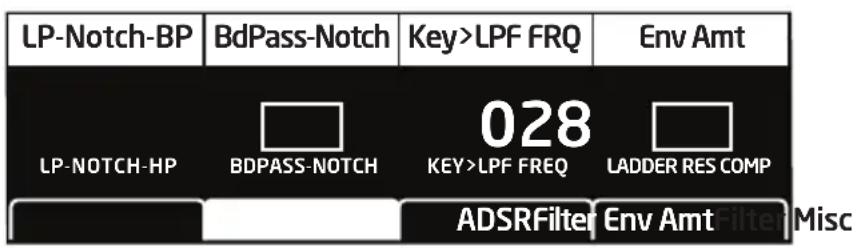
text_image
LP-Notch-BP BdPass-Notch Key>LPF FRQ Env Amt LP-NOTCH-HP BDPASS-NOTCH 028 KEY>LPF FREQ LADDER RES COMP ADSRFilter Env Amt MiscKey>LPF Freq: 0...127—Sets the amount of modulation from the keyboard to the filter's cutoff frequency. Any setting above zero means that the higher the note played on the keyboard, the more the filter opens. This is useful for adding brightness to a sound as higher notes are played, which is typically how acoustic instruments behave. When set to zero, keyboard filter tracking is off, meaning that filter frequency is unaffected by playing higher or lower notes on the keyboard. When set to 127, the filter will track in half-step increments, which can be useful if you are using the filter to generate a pitch through self-oscillation.
Ladder Res Comp: On, Off—In a classic ladder filter, increasing the amount of resonance decreases the amount of bass response. This parameter compensates for this by boosting bass frequencies as resonance is increased on Low-Pass 2 Filter. This parameter is on by default.
TAB 3 - ADSR
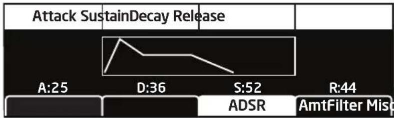
line
Attack SustainDecay Release | Category | Attack SustainDecay Release | A:25 | D:36 | S:52 | R:44 | |---|---|---|---|---|---| | ADSR | | | | | | | AmtFilter Misq | | | | | |Attack: 0...127—Sets the attack time of the envelope. The higher the setting, the slower the attack time and the longer it takes for the filter to open from the level set with the filter CUTOFF knob to the level set by the filter envelope amount. Percussive sounds typically have sharp (short) attacks.
Decay: 0...127—Sets the decay time of the envelope. After a sound reaches the filter frequency set at its attack stage, DECAY controls how quickly the filter then transitions to the cutoff frequency set with the SUSTAIN knob. The higher the setting, the longer the decay. Percussive sounds, such as synth bass, typically have shorter decays (and a generous amount of low-pass filter resonance).
Sustain: 0...127—Sets the filter cutoff frequency for the sustained portion of the sound. The sound will stay at this filter frequency for as long as a note is held on the keyboard.
Release: 0...127—Sets the release time of the envelope. This controls how quickly the filter closes after a note is released.

The description of envelope behavior just given is true when the AMOUNT parameter is set to a positive value. But since this control is actually bipolar, it is possible to set a negative amount of modulation. In this case, the envelopes are inverted and their behavior changes. The best way to get a feel for the difference is to experiment with both positive and negative settings of the AMOUNT parameter.

The cutoff frequency setting may limit the effect of the envelope on the filter. For example, in low-pass filter mode, if CUTOFF is at its highest setting, a positive envelope amount will have no effect on the filter since the filter is already completely open.
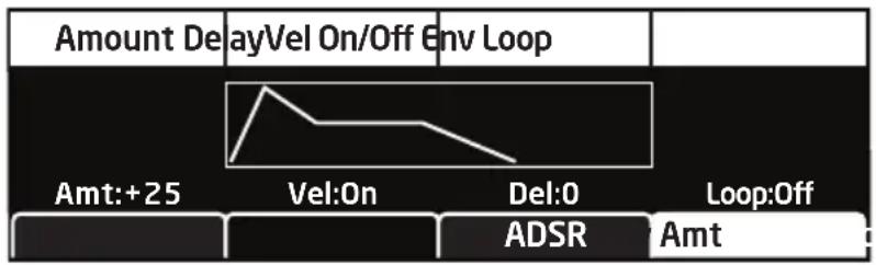
TAB 4 - Env Amt

text_image
Amount DelayVel On/Off Env Loop Amt:+25 Vel:On Del:0 Loop:Off ADSR AmtAmount: -127...127—Sets the amount of modulation from the filter envelope to the filter's cutoff frequency. Any setting above zero means that each time you strike a key, the filter envelope controls how the filter opens and closes. Higher amounts more dramatically affect the cutoff frequency. This control is bipolar. Positive settings produce standard behavior. Negative settings invert the envelope.
Velocity On/Off: On, Off—Allows key velocity to influence filter cutoff frequency. If on, the harder you play, the more the filter will open and the brighter the sound will be. If off, key velocity will not affect the filter. This control allows for more touch-sensitive sounds.
Delay: 0...127—Sets a delay between the time the envelope is triggered and when the Attack and subsequent stages occur.
Loop: Off, On—When on, the Delay, Attack, and Decay segments of the envelope repeat. Sustain still affects the level at which the Decay segment ends, but instead of sustaining at a fixed level while a note is triggered, Delay, Attack, and Decay loop until the note is turned off. The Release segment begins when the note is released, just as it does when Repeat is off.
Filter Envelope
The Pro 3 filter has a dedicated, 5-stage envelope generator (attack, decay, sustain, release, plus delay). The Filter Envelope is used to shape the harmonic characteristics of a synthesized sound by giving you filtering control with these stages.
This is one of the most important aspects of a synthesized sound. Without an envelope, the filters would be static and unchanging. They would stay open or closed by a fixed amount that wouldn't change over the duration of a sound. That's not very expressive or interesting to listen to — and it's not how most real-world instruments behave.
In general, sounds produced by an acoustic instrument are brighter at their beginning (the attack stage) and grow mellower as they die out (the decay and release stages). In other words, their harmonic content changes over time. This is exactly what the filter envelope is designed to emulate.
FILTER


Filter Envelope
line
| time | amplitude | | ---------- | --------- | | attack | 0 | | decay | Peak | | sustain | 0 | | release | 0 |A typical 5-stage DADSR envelope
To hear the effect of the Filter Envelope:
- Press the GLOBAL button and use Soft Knob 1 to navigate to the BASIC PROGRAM command, then press Soft Button 1 (WRITE NOW).
- Press the LOW-PASS 1 button to select this filter type.
- Hold down a note and rotate the filter's CUTOFF knob to set it to a value of 40 (refer to the main display to see its numeric value).
- Play a note. At this point you may not hear anything because you've closed the filter significantly.
- In the Envelopes section, turn the Filter Envelope's AMOUNT knob to a value of 50 (refer to the main display to see its numeric value).
- Play a note. Notice how the sound has changed. The Filter Envelope is controlling filter cutoff by the amount you set with the AMOUNT knob.
- Repeatedly strike a note on the keyboard as you turn the Filter Envelope's DECAY knob clockwise and counterclockwise. Notice how it changes the sound as the note decays faster or slower after its initial attack stage.
- Now experiment with the Filter Envelope's ATTACK knob. Notice how the attack becomes faster or slower.
- Now hold down a note and experiment with the Filter Envelope's SUSTAIN knob. This controls how wide the filter stays open while you hold down a key on the keyboard.
- The Filter Envelope's RELEASE parameter acts in conjunction with the Amplifier Envelope, so to hear its effect, first set the Amp Envelope's RELEASE value to 75.
- Now repeatedly strike a note on the keyboard as you turn the Filter Envelope's RELEASE knob clockwise and counterclockwise. Notice how the note fades out faster or slower as you change the RELEASE value.
- Continue experimenting with various Filter Envelope settings while you adjust the Filter Envelope's ENV AMOUNT knob. Notice how greater AMOUNT settings amplify the effect of the envelope on the filter.
As noted above, the Filter Envelope and Amplifier Envelope often work in conjunction, with the Filter Envelope controlling how the filter opens and closes and the Amplifier Envelope controlling how the Amplifier controls the overall volume shape of the sounds you create. To learn more about the Amplifier Envelope, see page 35.
Envelope Parameters (Front Panel)
Attack: 0...127—Sets the attack time of the envelope. The higher the setting, the slower the attack time and the longer it takes for the filter to open from the level set with the filter CUTOFF knob to the level set by the filter envelope amount. Percussive sounds typically have sharp (short) attacks.
Decay: 0...127—Sets the decay time of the envelope. After a sound reaches the filter frequency set at its attack stage, DECAY controls how quickly the filter then transitions to the cutoff frequency set with the SUSTAIN knob. The higher the setting, the longer the decay. Percussive sounds, such as synth bass, typically have shorter decays (and a generous amount of low-pass filter resonance).
Sustain: 0...127—Sets the filter cutoff frequency for the sustained portion of the sound. The sound will stay at this filter frequency for as long as a note is held on the keyboard.
Release: 0...127—Sets the release time of the envelope. This controls how quickly the filter closes after a note is released.
Velocity On/Off: On, Off—Allows key velocity to influence filter cutoff frequency. If on, the harder you play, the more the filter will open and the brighter the sound will be. If off, key velocity will not affect the filter. This control allows for more touch-sensitive sounds.
Amount: -127...127—Sets the amount of modulation from the filter envelope to the filter’s cutoff frequency. Any setting above zero means that each time you strike a key, the filter envelope controls how the filter opens and closes. Higher amounts more dramatically affect the cutoff frequency. This control is bipolar. Positive settings produce standard behavior. Negative settings invert the envelope.
Additional Filter Envelope Parameters (Display Menus)
Additional Filter parameters are accessible through the menus in the main display. To see these menus, adjust any of the filter envelope controls in the ENVELOPES section of front panel. The envelope parameters are in menu Tab 3 and Tab 4. The parameters explained below are the ones that don't appear on the front panel.
TAB4 - Env Amount
text_image
Amount DelayVel On/Off Env Loop Amt:+25 Vel:On Del:0 Loop:Off ADSR AmtDelay: 0...127—Sets a delay between the time the envelope is triggered (note on) and when the attack portion actually begins.
Loop: Off, On—When on, the Delay, Attack, and Decay segments of the envelope repeat. Sustain still affects the level at which the Decay segment ends, but instead of sustaining at a fixed level while a key is pressed, Delay, Attack, and Decay loop until the key is released. The Release segment begins when the key is released, just as it does when Repeat is off.
Amplifier Envelope
After passing through the filters, a synthesized sound goes into an amplifier, which controls its overall volume. The amplifier has a dedicated, 5-stage envelope generator (attack, decay, sustain, release, plus delay) which is used to shape the volume characteristics of a sound over time by giving you control over these stages. Along with the filter envelope, this is one of the most important aspects of a synthesized sound.
Without a volume envelope, the volume of a sound wouldn't change over the duration of a note. It would begin immediately, remain at its full volume for its duration of the note, then end immediately when the note was released. Again, that's not very interesting sonically and it's not typically how instruments behave in the real world.
To give you a real-world example, the main difference between the sound of the wind and the sound of a snare drum is that they have very different volume envelopes. Otherwise, they are essentially both white noise.
Wind has a relatively slow attack, a long sustain, and a long decay and release. A snare drum has a sharp attack, no sustain, and very little decay or release. But again, they are both fundamentally white noise.
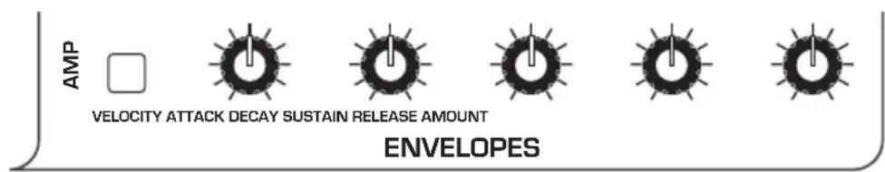
text_image
AMP VELOCITY ATTACK DECAY SUSTAIN RELEASE AMOUNT ENVELOPESAmplifier Envelope
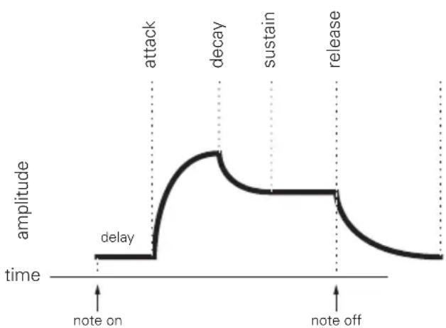
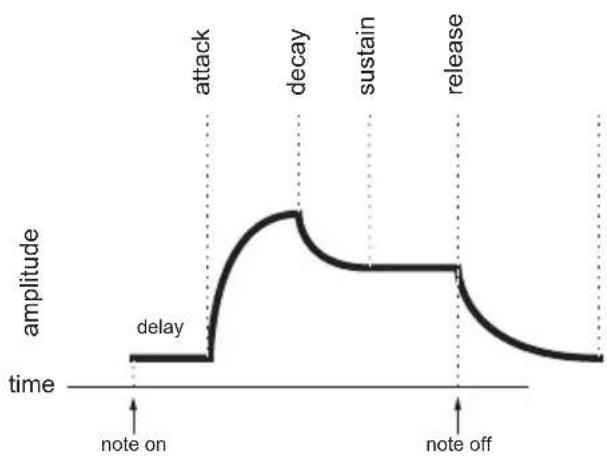
line
| time | amplitude | | ---------- | --------- | | note on | delay | | attack | | | decay | | | sustain | | | release | |A typical 5-stage, DADSR envelope
As noted previously, the Amplifier Envelope often works in conjunction with the Filter Envelope, with the Filter Envelope controlling how the filter opens and closes and the Amplifier Envelope controlling how the Amplifier controls the overall volume shape of the sounds you create.
To hear the effect of the Amplifier Envelope:
- Press the GLOBAL button and use Soft Knob 1 to navigate to the BASIC PROGRAM command, then press Soft Button 1 (WRITE NOW).
- Repeatedly strike a note on the keyboard as you turn the Amplifier Envelope's ATTACK knob clockwise. Notice how the attack becomes slower and more gradual the further you turn the knob.
- Reset the ATTACK parameter to zero.
- Next, repeatedly strike a note on the keyboard as you turn the Amplifier Envelope's SUSTAIN to zero. Notice how it changes the sound so that the sound no longer sustains even if you hold down the key. The only sound you hear is the decay portion of the sound.
- Now, with SUSTAIN still set to zero, repeatedly strike a note on the keyboard as you turn the Amplifier Envelope's DECAY knob clockwise and counterclockwise. Notice how it changes the sound as the note decays faster or slower after its initial attack stage.
- Reset the DECAY parameter to 127
- Finally, with DECAY set to 127 and SUSTAIN still set to zero, repeatedly strike a note on the keyboard as you turn the Amplifier Envelope's RELEASE knob clockwise. Notice how the release becomes longer the further you turn the knob.
- Continue experimenting with various Amplifier Envelope settings while you also adjust the Filter Envelope to hear how these two controls interact. You will understand how powerful the envelopes are and how essential they are to designing sounds.
Amplifier Envelope Parameters (Front Panel)
Attack: 0...127—Sets the attack time of the envelope. The higher the setting, the slower the attack time and the longer it takes for a sound to reach its full volume. Pads typically have softer (longer) attacks. Percussive sounds have sharper (shorter) attacks.
Decay: 0...127—Sets the decay time of the envelope. After a sound reaches its full volume at its attack stage, DECAY controls how quickly the sound transitions to the level set with the SUSTAIN control. The higher the setting, the longer the decay. Percussive sounds, such as synth bass, typically have shorter decays.
Sustain: 0...127—Sets the sustain level of the envelope. The higher the setting, the louder the sustained portion of the sound will be. The sound will stay at this level for as long as a note is held on the keyboard.
Release: 0...127—Sets the release time of the envelope. This controls how quickly a sound dies out after a note is released.
Env Amount: 0...127—Sets the amount of modulation from the Envelope to the VCA. In most cases you will probably want to set this fully clockwise for maximum VCA volume. If you experience signal clipping, try reducing the ENV AMOUNT.

To create a “gated VCA” effect, set the AMOUNT of the Amplifier Envelope to zero, route the LFO square wave to ENV VCA AMT with an AMOUNT setting of 127, and hold a note.
Velocity On/Off: On, Off—Allows key velocity to influence volume. If on, the harder you play, the louder sound will be. If off, key velocity will not affect the volume. This control allows for more touch-sensitive sounds.
Additional Amplifier Parameters (Display Menus)
Additional Amplifier Envelope parameters are accessible through the menus in the main display. To see these menus, adjust any of the controls in AMP portion of the ENVELOPES section of the front panel. The parameters explained below are the ones that don't appear on the front panel.
TAB 1 - VCA
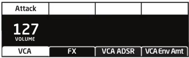
text_image
Attack 127 VOLUME VCA FX VCA ADSR VCA Env AmtVolume: 0...127—Sets the volume of the currently active program. Although the master output level of the Pro 3 is controlled by the front-panel MASTER VOLUME knob, the VOLUME parameter in this menu sets the volume of an individual program. This is useful for ensuring that your sounds have roughly the same volume from program to program.
TAB 4 - VCA Env Amount
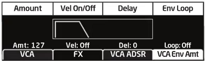
flowchart
graph TD
    A["Amount"] --> B["Vel On/Off"]
    B --> C["Delay"]
    C --> D["Env Loop"]
    E["Amt: 127"] --> F["Vel: Off"]
    F --> G["Del: 0"]
    G --> H["Loop: Off"]
    I["VCA"] --> J["FX"]
    J --> K["VCA ADSR"]
    K --> L["VCA Env Amt"]
Delay: 0...127—Sets a delay between the time the envelope is triggered (note on) and when the attack portion actually begins.
Loop: Off, On—When on, the Delay, Attack, and Decay segments of the envelope repeat. Sustain still affects the level at which the Decay segment ends, but instead of sustaining at a fixed level while a note is gated on, Delay, Attack, and Decay loop until the note is turned off. The Release segment begins when the note is gated off, just as it does when Repeat is off.
Auxiliary Envelopes
The Pro 3 has two additional 5-stage envelope generators (attack, decay, sustain, release, plus delay). They are useful for creating modulation that varies over time according to the shape of the envelope. Routing an envelope to an oscillator's frequency, for example, causes the oscillator's pitch to rise and fall according to the contour of the envelope.
As with all of the Pro 3's envelopes, there are controls for modulating the envelope amount using keyboard velocity. The Auxiliary Envelopes can be routed to any of the modulation destinations in the mod matrix. In addition, the Auxiliary Envelopes can repeat (loop) using the REPEAT function in the aux envelopes display menu. This is useful for cyclical 4-stage modulation.
There are many ways to make creative use of the Auxiliary Envelopes:
- Route an Auxiliary Envelope to one of the oscillators' COARSE FREQ parameter to create the classic “pitch blip” effect used in many synth lead sounds.
- Route an Auxiliary Envelope to the filter's CUTOFF parameter (in addition to the standard Filter Envelope) to create a more complex filter envelope shape.
- Route an Auxiliary Envelope to one or more of the oscillators' SHAPE parameter to make their timbre evolve according to envelope's contour.
- Route an Auxiliary Envelope with a fast attack and short decay to NOISE LEVEL to add a percussive attack to a sound. (Noise should be set to zero in the Mixer.)

Actually, any of the Pro 3's envelopes can be routed to any destination (or multiple destinations) using the modulation matrix. See "Modulation" on page 47 for more information.
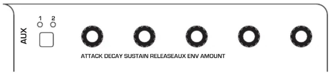
text_image
AUX 1 2 ATTACK DECAY SUSTAIN RELEASEAUX ENV AMOUNTAuxiliary Envelopes
Auxiliary Envelope Parameters (Front Panel)
1/2 Buttons: Selects either Auxiliary Envelope 1 or Auxiliary Envelope 2 for editing.
Velocity: On/Off—This button enables keyboard velocity to modulate the Envelope Amount.
Attack: 0...127—Sets the attack time of the envelope. The higher the setting, the slower the attack time.
Decay: 0...127—Sets the decay time of the envelope. This controls how quickly the value transitions from the attack level to the level set with the SUSTAIN control. The higher the setting, the longer the decay.
Sustain: 0...127—Sets the sustain level of the envelope. It will stay at this level for as long as a note is held on the keyboard.
Release: 0...127—Sets the release time of the envelope. This controls how quickly the value transitions to zero after a note is released on the keyboard.
Amount: -127...127—Sets the amount of modulation from the envelope to the selected modulation destination. Higher amounts more dramatically affect the destination. This control is bipolar. Positive settings produce standard behavior. Negative settings invert the envelope.
Additional Auxiliary Envelope Parameters (Display Menus)
Additional Envelope parameters are accessible through the menus in the main display. To see these menus, adjust any of the controls in AUX ENV section of the front panel. The parameters explained below are the ones that don't appear on the front panel.
TAB 1 - Aux 1 Destination

flowchart
graph TD
    A["Destination"] --> B["Off"]
    B --> C["DESTINATION"]
    C --> D["Aux 1 Dest"]
    C --> E["Aux 1 ADSR"]
    C --> F["Aux 1 Env Amt"]
Destination: Various—Selects a modulation destination for the Auxiliary Envelope. See “Appendix B:
Modulation Destinations" on page 120 for a list of possible destinations.

You can quickly assign an aux envelope to a destination by holding the AUX ENV button and turning a knob on the front panel. The currently selected aux envelope will be assigned to the touched parameter.
TAB 3 - Aux 1 Env Amount
| Amount | Vel On/Off | Delay | Env Repeat |
| AMT: 127 | Vel: Off | Del: 0 | Rept: Off |
| Aux 1 Dest | Aux 1 ADSR | Aux 1 Env Amt | |
Velocity On/Off: On, Off—Allows key velocity to influence the mount of modulation applied. If on, the harder you play, the more the Aux Envelope will affect the chosen modulation destination. If off, key velocity will not affect the amount of modulation from the Auxiliary Envelope.
Delay: 0...127—Sets a delay between the time the envelope is triggered (note on) and when the attack portion actually begins.
Loop: Off, On—When on, the Delay, Attack, and Decay segments of the envelope repeat. Sustain still affects the level at which the Decay segment ends, but instead of sustaining at a fixed level while a key is held down, Delay, Attack, and Decay loop until the key is released. (The Release segment begins when the key is released, just as it does when Repeat is off.)
Low Frequency Oscillators
The three LFOs are special-purpose oscillators that produce a frequency that is typically below the range of human hearing (although these can actually extend into the audio range if set to their maximum frequency). The LFOs are typically used for periodic modulation such as vibrato (periodic pitch modulation) and tremolo (periodic amplitude modulation). They can also be used as modulation sources for any of the many modulatable parameters in the Pro 3.
The LFOs produce a variety of waveshapes, including triangle, sawtooth, reverse sawtooth, square, and s&H (sample & hold/random). Though most often used for low-frequency modulation, the Pro 3 LFOs can actually function at speeds that extend into the audible range for extreme effects.
text_image
1 2 3 FREQUENCY AMOUNT - + W W N U S&H O O O O □ □ DESTINATIONSHAPE LFOThe Low Frequency Oscillators
Triangle and Sample & Hold waves are bipolar. That is, their waveshape is positive for half of their cycle and negative for the other half. In the case of the triangle wave, this makes it possible to generate a vibrato that goes alternately sharp and flat in equal amounts on either side of a center frequency. Random, also known as “sample and hold,” generates a series of random values, each held for the duration of one cycle.
The square wave, sawtooth, and reverse sawtooth generate only positive values. In the case of the square wave, this makes it possible to generate natural-sounding trills.

line
| Waveform | - polarity | | -------- | ---------- | | Triangle | 0 | | Sawtooth | 0 | | Square Sample & HoldSawtooth Reverse | 0 |The LFOs can be free-running or synced to the Arpeggiator, Sequencer, or MIDI clock for tempo-synced effects such as filter sweeps, tremolo, and so on.
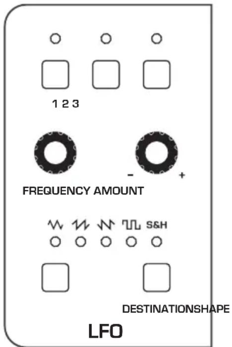
LFO Parameters (Front Panel)
Frequency: 0...150—Sets the frequency of the selected LFO from a slow .022Hz to a fast 500Hz. This is affected by the CLK SYNC (clock sync) parameter as explained below.
Amount: 0...127—Sets the amount of LFO modulation routed to the selected destination. Setting an amount here applies the selected modulation continuously. You can also use the modulation matrix to route an LFO to additional destinations and use a different modulation amount if you want.
Shape: Triangle, Sawtooth, Reverse Sawtooth, Square, S&H—This button sets the waveshape of the selected LFO.
Destination: Various—Routes the selected LFO to one of the many modulation destinations within the synthesizer. These appear in the display. You can also use the modulation matrix to route an LFO to additional destinations.
There are many ways to make creative use of the LFOs:
- Route the LFO to the COARSE FREQ parameter of the oscillators to create vibrato (TRIANGLE wave) or random pitches (S&H/RANDOM wave).
- Route the LFO's triangle wave to the filter's CUTOFF parameter and use a medium FREQ and AMOUNT setting to create a wah-wah effect, or use a slow FREQ setting and low AMOUNT setting to create subtle harmonic movement.
- Route the LFO's square wave to the amplifier's AMOUNT parameter and use a medium FREQ and AMOUNT setting to create a tremolo effect.
- Route an LFO to an oscillator's SHAPE parameter to make its timbre evolve. This can be particularly interesting when using Oscillator 3 wavetables.
- Route the LFO's triangle wave to the TIME parameter of the stereo delay and use a slow FREQ and low AMOUNT setting to create a chorus effect.

Any LFO can be routed to any destination (or multiple destinations) using the modulation matrix. See page 120 for a list of destinations.
Additional LFO Parameters (Display Menus)
Additional LFO parameters are accessible through the menus in the main display. To see these menus, adjust any of the controls in LFO portion of the front panel.
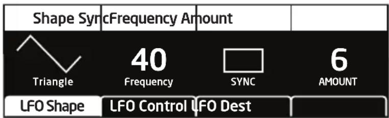
TAB 1 - LFO Shape
text_image
Shape Sync Frequency Amount Triangle 40 Frequency SYNC 6 LFO Shape LFO Control LFO DestShape: Triangle, Sawtooth, Reverse Sawtooth, Square, Random—This button sets the waveshape of the selected LFO.
Frequency: Sets the frequency of the selected LFO from a slow .022Hz to a fast 500Hz. This is affected by the SYNC (clock sync) parameter, when on.
Sync: When on, the LFO synchronizes with the master clock, which controls the Arpeggiator, Sequencer, and certain effects.
Amount: Sets the amount of LFO modulation routed to the selected destination. Setting an amount here applies the selected modulation continuously. You can also use the modulation matrix to route an LFO to additional destinations and use a different modulation amount.
TAB 2 - LFO Control

text_image
Slew Rate Wave ResetPhase 0 SLEW RATE 0 PHASE WAVE RESET LFO Control F0 Shop BestSlew Rate: 0...127—Slew adds a smoothing effect to a control parameter by affecting its rate of change. You can think of it as glide/portamento for control voltages. For example, if you apply a high SLEW RATE value to the LFO's pulse wave, its sharp-edges will be smoothed and it will become more like a sine wave. The same is true when applied to the s&H/RANDOM LFO waveshape: the abrupt changes will be smoothed.
Phase: 0...127—Use Phase to offset the LFO waveshape's start point. For Phase to have any noticeable effect, WAVE RESET must also be enabled for that LFO. If the LFO is free-running—that is, with WAVE RESET off—there is no fixed start point from which the phase can be offset. This is useful for modifying the shape of the chosen LFO waveshape.
Wave Reset: Off, On—When off, the LFO is free running. When on, the LFO is re-started each time a new note is played. WAVE RESET is set independently for each LFO. This is useful if you want to ensure that the full waveshape is applied each time you strike a key.
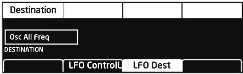
TAB 3 - LFO Dest
flowchart
graph TD
    A["Destination"] --> B["Osc All Freq"]
    B --> C["DESTINATION"]
    C --> D["LFO ControlL"]
    C --> E["LFO Dest"]
Destination: Routes the selected LFO to one of the many modulatable destinations within the synthesizer. You can also use the modulation matrix to route an LFO to additional destinations.

There is a shortcut for routing an LFO to a front-panel destination (provided that the destination is a valid destination). Simply hold down the selector button of the desired LFO or the LFO's DESTINATION button, then move the knob or control you want to use as a destination (the filter cutoff, for example). Set the amount using the LFO AMOUNT knobs. Be aware that not all front-panel controls can be used as a modulation destinations.
Modulation
Although the overall sonic character of the Pro 3 is determined by its oscillators and filters, much of its power to make truly unique sounds comes from creative use of modulation. Modulation is the process of routing one parameter (used as a control voltage) to another parameter in order to change the way the targeted parameter behaves.
| Edit Mod 1 | Source | Amount | Destination | |
| Mod 1 | Slider 1 | 60 | Cutoff | |
| Mod 2 | Slider 2 | 35 | Osc1 Shape | |
| Mod 3 | Aftertouch | 25 | Drive | |
| Mod4 | Mod Wheel | 80 | LFO1 Amt | |
| Slot Sort | Sort Source | Sort Dest | ||
The Modulation Matrix
The concept is simple:
- Choose a source.
-
Choose a destination.
-
Set an amount. The amount can either be positive or negative.
You already understand and apply the concept of modulation whenever you use the filter envelope to control the filter's cutoff frequency. In this case, the modulation source is the filter envelope (or more precisely, any of its controls, such as attack, decay, sustain, or release). The modulation destination is the filter's CUTOFF frequency. The modulation amount is set with the Filter Envelope's AMOUNT knob.
There are 46 different modulation sources and 171 different destinations to choose from. (See page 119 for a complete list.) There are also 32 freely assignable modulation paths (mod slots 1-32) as well as 5 additional dedicated mod sources including LFO 1-3, and Auxiliary Envelope 1 and 2. This gives you a large number of sound-shaping options.

text_image
MODULATION SOURCE DESTINATION AMOUNTThe Modulation section

There are shortcuts for routing modulation to various front panel sources/destinations. Simply hold down the SOURCE button and move the control you want to use as a source (the Mod wheel, for example). Then hold down the DESTINATION button and move the control that you want to use as a destination (filter cutoff, for example). Set the amount with the AMOUNT knob while referring to the display. Be aware that not all front-panel controls can be used as a modulation sources/destinations.
Modulation Parameters (Front Panel)
Source: Selects a modulation source. The are 34 different modulation sources. See page 119 for a complete list.
Destination: Selects a modulation destination. The are 88 different modulation destinations. See page 120 for a complete list.
Amount Sets the modulation amount. Modulation can be either positive or negative.
Additional Mod Matrix Parameters (Display Menu)
Additional mod matrix parameters are accessible through the menus in the main display. To see these, press the SOURCE or DESTINATION button on the front panel.
Sort Slot: Arranges the modulation list in order of slot number (1-32)
Sort Source: Arranges the modulation list by modulation source. LFOs are grouped together, envelopes are grouped together, and so on.
Sort Dest: Arranges the modulation list by modulation destination. Oscillator parameters are grouped together, effects parameters are grouped together, and so on.
Modulation Examples
Here are several modulation scenarios that illustrate how to use the modulation matrix. The examples provide step-by-step instructions for clarity. Some of these setups are built into the basic program, which you can recall from the GLOBAL menu.
To use the Mod wheel to add vibrato:
-
In the LFO section, set LFO 1 to TRIANGLE and set FREQUENCY to 75. Set DESTINATION to OSC ALL FREQ. Set AMOUNT to 0. (You will control the amount with the Mod wheel.)
-
In the MODULATION section, press the SOURCE button. Use SOFT KNOB 1 to scroll to Mod Slot 1 if it's not already displayed.
-
Use SOFT KNOB 2 to scroll through the various mod sources and choose MOD WHEEL (As a shortcut you can hold down the SOURCE button and move the Mod wheel.)
-
Use Soft KNOB 3 to set the amount to 30.
-
Use SOFT KNOB 4 to scroll through the various mod destinations and choose LFO1 AMT.
-
Hold down a note on the keyboard and turn the Mod wheel. You should hear vibrato.

Use PRESSURE as the modulation source instead of the Mod wheel in the previous example to add vibrato with key pressure/aftertouch.
To use the Touch slider to control the filter cutoff:
-
In the MODULATION section, press the SOURCE button. Use SOFT KNOB 1 to scroll to Mod Slot 1 if it's not already displayed.
-
Use SOFT KNOB 2 to scroll through the various mod sources and choose SLIDER.
-
Use SOFT KNOB 4 to scroll through the various mod destinations and choose CUTOFF.
-
Hold down a note on the keyboard (or press the HOLD button and play a note on the keyboard) and move a finger up and down the Touch slider.
-
Use SOFT KNOB 3 to set the amount to your preference. Higher AMOUNT settings cause the filter to open wider the farther up you move your finger along the Touch slider. A negative amount setting will close the filter farther up you move your finger along the Touch slider.

Use PRESSURE as the modulation source instead of the Touch slider in the previous example to open the filter (positive AMOUNT) or close the filter (negative AMOUNT) with pressure.
Other modulation ideas:
- To create the classic “attack pitch blip” effect in many synth brass sounds, choose a good three-oscillator synth brass sound then route Aux Envelope 1 to osc 2 COARSE FREQ and set Aux Envelope 1 to Attack: 0, Decay: 30, Sustain: 0, and Release: 0 with an amount of 18.
- Route an LFO to PAN to create an auto-panning effect. Panning width is controlled by the modulation amount. Panning speed is controlled by the LFO frequency. Add a second mod path to control the LFO speed with the Mod wheel for a controllable rotating speaker spin-up/spin-down effect. Add the rotating speaker effect as Effect 1 and set up a third mod path to control FX1 MIX with the Mod wheel for even better results.
- Route VELOCITY to DISTORTION to overdrive a synth lead sound the harder you play.
- Tune Oscillator 3 to a perfect 5th (7 semitones) and set its mixer level to 0. Then create a mod path to control Osc 3 LEVEL with the Mod wheel or Touch slider so you can add it to the mix in live performance. Finally, add DISTORTION to the sound and you can create a convincing “guitar-with-controllable-feedback” effect.
Effects
You can add two digital effects to any Pro 3 program. Not all sounds need effects to make them interesting, but adding a touch of delay or reverb can add a sense depth, just as adding chorus, flanging, or phasing can add movement. Effects settings are saved individually with each program.
If you enable SYNC for time-based effects such as the delays, their repeat rate is synchronized to the Arpeggiator, Sequencer, or MIDI clock for repeats that occur on the beat.
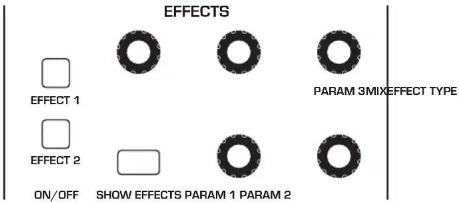
text_image
EFFECTS PARAM 3MIXEFFECT TYPE □ EFFECT 1 □ EFFECT 2 □ ON/OFF SHOW EFFECTS PARAM 1 PARAM 2The Effects section
Effects:
- Stereo Delay - classic digital delay
• BBD Delay - vintage bucket-brigade emulation
- Chorus - vintage chorus
- Flanger - vintage through-zero flanger
- Phaser - vintage 6-stage phaser
• HP Filter - high-pass filter.
• Ring Mod - ring modulation
- Rotating Speaker - vintage rotating speaker emulation
- Super Plate Reverb - plate reverb with variable time, tone, and early reflections. Available on Effect 2 only.

For best results, run the flanger and high-pass filter 100% wet (set the MIX parameter to 127).
To use Effects:
- Press the EFFECT 1 button to turn on effect 1.
- Press Soft Button 2 (FX1 PARAMS) in the display to select effect 1 for editing.
- Turn the EFFECT TYPE knob to choose an effect.
- Turn the MIX knob to blend in a good amount of the processed signal. You'll want to be able to clearly hear the effect when you tweak its settings. You can dial it down afterward.
- Use the PARAM 1, PARAM 2, and PARAM 3 knobs to adjust the effect's parameters to your taste. See "Effects Parameters" on page 52 for details on the adjustable parameters on each effect type.
- Finally, adjust the MIX knob again to optimize the amount of the effect. Full left is completely dry. Full right is completely wet (a 100% processed signal).
- To sync a delay to the Arpeggiator or Sequencer, enable its SYNC parameter and adjust the TIME parameter (Parameter 1) as needed.
Effects Parameters (Front Panel)
Effect 1: Turns effect 1 on or off.
Effect 2: Turns effect 2 on or off.
Effect Type: stereo delay, bbd delay, chorus, flanger, phaser, HP filter, ring mod, rotating speaker, super plate—Selects the effect type.
Show Effects: Shows the Effects menu in the display for editing. Pressing this button more than once toggles between the two effects in the display.
Mix: 0...127—Sets the balance between the processed (wet) signal and unprocessed (dry) signal. Full left is completely dry. Full right is completely wet.
Sync (in the main display): On, Off—When a delay effect is chosen, this enables syncing of the timed delay repeats (feedback) to the Arpeggiator, Sequencer, or MIDI clock. When SYNC is on, delay time has the following values:
| Value Delay Time | |
| Whole (1) 4 beats | |
| Half dot (2D) 3 beats | |
| Half (2) 2 beats | |
| Quarter dot (4D) 1 1/2 beats | |
| Quarter (4) 1 beat | |
| Quarter triplet (4T) 1 1/3 beats | |
| 8th dot (8D) 3/4 of 1 beat | |
| 8th (8) 1/2 of 1 beat | |
| 8th triplet (8T) 1/3 of 1 beat | |
| 16th dot (16D) 3/8 of 1 beat | |
| 16th (16) 1/4 of 1 beat | |

Maximum delay time is approximately 1 second. The combination of longer synced delay times with slower tempos can result in delay times that would be greater than 1 second. When that happens, the delay time is divided by 2 until it no longer exceeds the 1 second limit. For example, if the BPM is set to 60 and Delay Time (Parameter 1) is set to Half, the expected delay time would be 2 seconds. The actual delay time will be 1 second (i.e. 2 seconds divided by 2).
Parameter 1: Variable, depending on the effect—This knob adjusts parameter 1 for the chosen effect. Each effect has three adjustable parameters, which differ depending on the effect.
Parameter 2: Variable, depending on the effect—This knob adjusts parameter 2 for the chosen effect. Each effect has three adjustable parameters, which differ depending on the effect.
Parameter 3: Variable, depending on the effect—This knob adjusts parameter 3 for the chosen effect. Each effect has three adjustable parameters, which differ depending on the effect.
| Effect Type Param 1 Param 2 Param 3 | |||
| stereo delay delay time feedback amount | low-pass filter cutoff | ||
| BBD delay delay time feedback amount | low-pass filter cutoff | ||
| chorus depth rate low-pass filter cutoff | |||
| flanger depth rate feedback | |||
| phaser depth rate feedback | |||
| high-pass filter frequency resonance | |||
| ring mod frequency track | shape | ||
| rotating speaker drive | speed | mic distance | |
| super plate reverb time | tone | pre-delay | |

To recreate a classic time-shifting effect on the stereo or BBD delay, try adjusting the delay time parameter in real time. You can also route an LFO or envelope to the delay's Time parameter using the modulation matrix.
Arpeggiator
The Arpeggiator allows you to hold a chord and the synthesizer will play a pattern based on the individual notes held. You can adjust the playback mode (up, down, up+down, random, assign.), the octave range (1, 2, or 3), the number of repeats per note, and the tempo. The Arpeggiator usually works best on sounds with a fast attack.
While you hold down a chord, pressing any additional notes will add those notes to the arpeggio. You can change chords and notes and the arpeggio will continue to play as long as at least one note is always held.
You can also use the HOLD feature with the Arpeggiator. When you enable HOLD, you can release the notes on the keyboard and the arpeggio will continue to play — with any additional notes that you play added to the arpeggio.

To prevent the Arpeggiator from adding new notes to an arpeggio when keys are continuously held (and instead start a new arpeggio each time you change notes), turn arp relatch on in the Arpeggiator. To do this, press the Arpeggiator's ON/OFF button and turn Soft Knob 3 to turn arp relatch on in the display.
Set the tempo of the Arpeggiator with the TAP TEMPO or BPM and DIVIDE controls. To use TAP TEMPO, tap this button 4 times to set the tempo. You can also sync the Arpeggiator to external MIDI clock, or even an external audio signal.

The Arpeggiator can run concurrently with the Sequencer for arpeggiated patterns with sequenced parameter automation. To do this, turn on the Arpeggiator and set the Sequencer mode to TRIGGER. The Sequencer will step with each Arpeggiator step. You can even record parameter changes during Arpeggiator playback by holding down the Sequencer's RECORD button and turning knobs to make parameter changes in real time. The parameter changes will be recorded and included in the sequence.


Press to enable the Arpeggiator
BPM DIVIDE SWING ARPEGGIATOR
10 11 12 13 14 15 16


assign 6 assign 7 assign 8 CV out 1 CV out 2 CV out 3 CV out 4

○ Normal
○ Gated
○ Trigger
fwd

rev fwd/rev random


RESETDIRECTION
MODE
The Arpeggiator
To use the Arpeggiator:
- Press the ARPEGGIATOR ON/OFF button to turn it on.
- Hold down one or more notes on the keyboard. The Arpeggiator plays them according to the settings you've chosen.
- To latch arpeggiation on (so that you don't have to continuously hold down notes) press the HOLD button.
- In the display menu, adjust settings such as MODE, OCTAVE RANGE, REPEATS, and BPM.
- To synchronize a delay effect to the Arpeggiator, enable Effect 1 or Effect 2, choose a delay, then turn on SYNC in the delay's parameter page in the display. Adjust the delay's TIME parameter as desired.
Arpeggiator "Momentary Sustain" Mode
The Pro 3 allows you to use the sustain pedal to turn the Arpeggiator's Hold function on and off and perform other Arpeggiator-related functions. To access this feature, use the FOOTSWITCH FUNCTION setting in the GLOBAL menu.
There are three modes to choose from:
- SUSTAIN - With the Arpeggiator running in this mode, pressing and holding the Sustain pedal sustains the notes, as the Sustain pedal normally would.
- ARP HOLD - With the Arpeggiator running in this mode, pressing the Sustain pedal once causes the Arpeggiator to hold the sequence (even when you release the notes on the keyboard). Pressing it again stops the Arpeggiator.
- ARP HOLD MOM - With the Arpeggiator running in this mode, pressing and holding the Sustain pedal causes the Arpeggiator to sustain (even when you release the notes on the keyboard) for as long as you hold down the pedal. Releasing the Sustain pedal stops the Arpeggiator.
To select the Arpeggiator's sustain pedal mode:
- Press the GLOBAL button then use Soft Knob 1 to scroll to FOOTSWITCH FUNCTION.
- Use Soft Knob 3 to select SUSTAIN, ARP HOLD, or ARP HOLD MOM, depending on your preference. Press the GLOBAL button again to exit the Global menu.
MIDI Note Output from the Arpeggiator
The Arpeggiator outputs MIDI note messages. Any notes that you hold on the keyboard will be arpeggiated according to the current settings of the Arpeggiator and output over MIDI as MIDI notes. You can use this feature to drive other MIDI-equipped devices such as synthesizers and drum machines. To access this feature, use the MIDI ARP NOTES setting in the GLOBAL menu.
To enable MIDI Note output from the Arpeggiator:
- Press the GLOBAL button, then turn Soft Knob 1 to select MIDI ARP NOTES.
- Turn Soft Knob 3 to select ON.
To control an external MIDI device:
- Connect the MIDI or USB output of the Pro 3 to the MIDI or USB input of the external device, depending on which type of connection the external device requires.
- On the Pro 3, press the GLOBAL button, then use Soft Knob 1 to select MIDI OUT SELECT.
- Use the Soft Knob 3 knob to select MIDI, or USB, or MIDI+USB, depending on how your Pro 3 and external device are connected.
- Press the GLOBAL button again to exit the Global menu.
- On the external device, set the the MIDI Channel and MIDI Receive port to match the Pro 3.
- Hold down a chord on the Pro 3 or start Sequencer playback. The external device should be triggered by the arpeggiated or sequenced notes.
Arpeggiator Parameters (Display Menus)
Arpeggiator parameters are accessible through the menus in the main display. To see these menus, adjust any of the controls in ARPEGGIATOR section of the front panel.
Front Panel Arpeggiator On/Off Button—This button turns the Arpeggiator on and off.
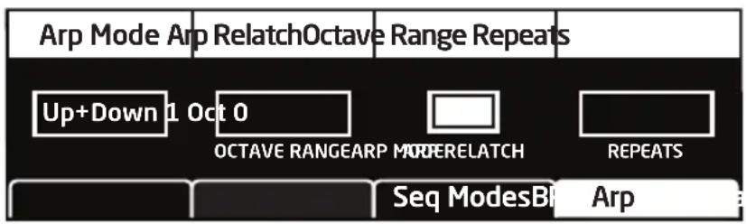
text_image
Arp Mode Arp RelatchOctave Range Repeats Up+Down 1 Oct 0 OCTAVE RANGEARP LOWERELATCH REPEATS Seq ModesBI ArpArp Mode: Sets the order in which notes play when the Arpeggiator is on. See the table.
| Arp Mode Behavior | |
| Up Plays from | lowest to highest note |
| Down Plays from | highest to lowest note |
| Up + Down Plays | from lowest to highest and back to lowest |
| Random Plays | notes in random order |
| Assign | Plays notes in the order the keys were pressed |
Octave Range: 1, 2, 3 —Set to 1, only the held notes are arpeggiated. Set to 2, the held notes and the notes one octave above them arpeggiate. Set to 3, the held notes and the notes one and two octaves above them arpeggiate.
Relatch: Off, On—Works in conjunction with HOLD. When HOLD and the Arpeggiator are on, and ARP RELATCH is off, played notes are held on and arpeggiated, with additional played notes added to the held notes and the arpeggio. When ARP RELATCH is on, played notes are held on and arpeggiated, but additional played notes will restart the arpeggio with the new notes.
Repeats: 1, 2, 3 —Set to 1, each note in the arpeggio plays once. Set to 2, each note in the arpeggio plays twice. Set to 3, each note in the arpeggio plays three times.
Clock Parameters
BPM: 30...250—Sets the tempo for the Arpeggiator in BPM (beats per minute). The TAP TEMPO LED flashes at the BPM rate. When SYNC is enabled on the low-frequency oscillator, or enabled in the Effects section, the BPM rate affects the LFO frequency and/or delay effect. When syncing to an external MIDI clock source, the BPM setting has no effect.
Divide—Selects a basic note value relative to the BPM. See the table below:
| Name Tempo Timing Division | ||
| Half BPM/2 Half note | ||
| Quarter BPM Quarter note | ||
| 8th BPM x 2 Eighth note | ||
| 8 Trip BPM x 3 Eighth note triplets | ||
| 16th BPM x 4 Sixteenth note | ||
| 16 Trip BPM x 6 Sixteenth note triplets | ||
| 32nd BPM x 8 Thirty-second note | ||
| 32 Trip BPM x 12 Thirty-second note triplets | ||
| 64th BPM x 16 Sixty-fourth note | ||
Tap Tempo—Pressing the TAP TEMPO button 4 times sets the tempo. The LED flashes at the BPM rate you set.
Sequencer
The original Sequencers in modular synthesizers were used as a modulation source. They produced a series of control voltage events at timed intervals that could be used to change the value of a synth parameter in discrete steps. Sequences could be routed to oscillator frequency to produce a series of pitched notes, to filter frequency to produce stepped filtering effects, and so on.
The Pro 3 Sequencer is like its analog precursors but more powerful. The Pro 3 Sequencer has 16 tracks and 4 linkable 16-step phrases (A,B,C,D) for creating repeating patterns of notes, or 3-note chords in paraphonic mode.
You can create sequences of variable length and add rests, ties, per-step ratcheting, and adjust duration, and velocity. Each Sequencer track can be routed to a different modulation destination using the mod matrix, and each step in a sequence can be set to a different value to modulate that destination.
All factory programs have a sequence associated with them. Recall a program and press the Sequencer's PLAY button to hear its associated sequence.
Normal, Gated, and Trigger Modes
The Sequencer has three modes of operation that control how sequence playback is started: Normal, Gated, and Trigger.
Normal — In NORMAL mode, sequence playback starts when you press the PLAY button.
Gated — In GATED mode, sequence playback starts and continues as long as you hold down a key on the keyboard.
Trigger — In TRIGGER mode, sequence playback is initiated by a specific type of trigger:
- Keyboard trigger. Repeatedly pressing a key on keyboard advances the sequence one step each time you press a key.
- The Arpeggiator. Selecting TRIGGER mode, then turning on the Arpeggiator and holding down a chord on the keyboard runs the sequence while notes are held. In this case, sequenced Note tracks are ignored and only parameter automation tracks are played. This is useful for adding sequenced filter sweeps or other modulation to an arpeggio.
- External input trigger. External input triggers include an external audio input signal, MIDI, or a control voltage input.

text_image
SLEWSEQ LOCKCUE PGM BPM DIVIDE SWINGTAP TEMPO ARPEGGIATORVALUE 1 2 3 4 5 6 7 8 9 10 11 12 13 14 15 16 notes/vel duration ratchet cutoff assign 1 assign 2 assign 3 assign 4 assign 5 assign 6 assign 7 assign 8 CV out 1 CV out 2 CV out 3 CV out 4 A B C D TRACK SEL SEQUENCE RECORD PLAY——MODE Normal fwd rev fwd/rev random Trigger DIRECTION RESETThe Sequencer

text_image
Play Source Sync to Trk 1 Restart Para Seq Keyboard SYNC TO TRK1 On Off PLAY SOURCE RESTART PARA SEQ BPM Seq Param Seq Modes ArpThe Sequencer Parameters menu (press the ARPEGGIATOR button to display)

other
| Step | Notes | Velocity | Duration | Note C5 | Vel: 80 | |---|---|---|---|---|---| | A1 | C 5 | (value not labeled) | (value not labeled) | (value not labeled) | (value not labeled) | | 1 | (value not labeled) | (value not labeled) | (value not labeled) | (value not labeled) | (value not labeled) | | 2 | (value not labeled) | (value not labeled) | (value not labeled) | (value not labeled) | (value not labeled) | | 3 | (value not labeled) | (value not labeled) | (value not labeled) | (value not labeled) | (value not labeled) | | 4 | (value not labeled) | (value not labeled) | (value not labeled) | (value not labeled) | (value not labeled) | | 5 | (value not labeled) | (value not labeled) | (value not labeled) | (value not labeled) | (value not labeled) | | 6 | (value not labeled) | (value not labeled) | (value not labeled) | (value not labeled) | (value not labeled) | | 7 | (value not labeled) | (value not labeled) | (value not labeled) | (value not labeled) | (value not labeled) | | 8 | (value not labeled) | (value not labeled) | (value not labeled) | (value not labeled) | (value not labeled) | | 9 | (value not labeled) | (value not labeled) | (value not labeled) | (value not labeled) | (value not labeled) | | 10 | (value not labeled) | (value not labeled) | (value not labeled) | (value not labeled) | (value not labeled) | | 11 | (value not labeled) | (value not labeled) | (value not labeled) | (value not labeled) | (value not labeled) | | 12 | (value not labeled) | (value not labeled) | (value not labeled) | (value not labeled) | (value not labeled) | | 13 | (value not labeled) | (value not labeled) | (value not labeled) | (value not labeled) | (value not labeled) | | 14 | (value not labeled) | (value not labeled) | (value not labeled) | (value not labeled) | (value not labeled) | | 15 | (value not labeled) | (value not labeled) | (value not labeled) | (value not labeled) | (value not labeled) | | 16 | (value not labeled) | (value not labeled) | (value not labeled) | (value not labeled) | (value not labeled) | | 17 | (value not labeled) | (value not labeled) | (value not labeled) | (value not labeled) | (value not labeled) | | 18 | (value not labeled) | (value not labeled) | (value not labeled) | (value not labeled) | (value not labeled) | | 19 | (value not labeled) | (value not labeled) | (value not labeled) | (value not labeled) | (value not labeled) | | 20 | (value not labeled) | (value not labeled) | (value not labeled) | (value not labeled) | (value not labeled) | | 21 | (value not labeled) | (value not labeled) | (value not labeled) | (value not labeled) | (value not labeled) | | 22 | (value not labeled) | (value not labeled) | (value not labeled) | (value not labeled) | (value not labeled) | | 23 | (value not labeled) | (value not labeled) | (value not labeled) | (value not labeled) | (value not labeled) | | 24 | (value not labeled) | (value not labeled) | (value not labeled) | (value not labeled) | (value not labeled) | | 25 | (value not labeled) | (value not labeled) | (value not labeled) | (value not labeled) | (value not labeled) | | 26 | (value not labeled) | (value not labeled) | (value not labeled) | (value not labeled) | (value not labeled) | | 27 | (value not labeled) | (value not labeled) | (value not labeled) | (value not labeled) | (value not labeled) | | 28 | (value not labeled) | (value not labeled) | (value not labeled) | (value not labeled) | (value not labeled) | | 29 | (value not labeled) | (value not labeled) | (value not labeled) | (value not labeled) | (value not labeled) | | 30+10000000000000000000000000000000000000000000000000000000000000000000000000000000000000000000000000000The sequence editor (press the TRACK SEL button to display)
Programming the Sequencer
By default, Track 1 of the Sequencer controls oscillator frequency, meaning that it's hard-wired for recording notes. Beyond that, any Sequencer track can be routed to any modulation destination. A typical scenario might have other tracks routed to filter cutoff, filter resonance, noise level for drum-like accents, and so on.
To program a monophonic note sequence:
- Select a program with a relatively sharp attack and short release.
- Press the RECORD button. Phrase A is selected by default.
- Play a sequence of notes on the keyboard. The numbered step LEDs indicate where you are in the sequence. A white LED indicates the current step. A red LED indicates a note has been recorded on that step.
- If you make a mistake, toggle the RECORD button off, then on again, and replay the notes correctly.
- If you want to record fewer than 16 steps, play only the notes you want. If you play more than 16 notes/steps, the Sequencer will ignore the additional notes.
- When you've finished, press the PLAY button to hear your sequence. A white LED indicates the current step. A red LED indicates a note has been recorded on that step.
- Use the BPM, DIVIDE, or TAP TEMPO controls to adjust Sequencer playback speed.
- To change playback direction of the sequence, press one of the DIRECTION buttons (REV, FWD/REV, RANDOM).
- To stop playback, press the PLAY button again.
- To save the sequence, save the program by pressing the WRITE button twice.

A quick way to edit a step when playback is stopped is to press and hold the step LED for the desired step. You can then play a note and the Sequencer will update the sequence to use that note and the velocity at which you played it. You can also edit any other parameter for that step while you're at that step location.
To transpose a sequence up or down during playback:
- Press the PLAY button to hear the sequence.
- Press a note on the keyboard above or below middle C. The sequence is transposed to that key. (Middle C plays the sequence as recorded.) For greater range, use the Transpose Up or Transpose Down buttons.
- During playback, if you want to restart a sequence from step 1, press the RESET button.
To record over an existing note sequence:
- Press the RECORD button.
- Play different notes on the keyboard. The numbered step LEDs indicate which step you're on.
- When you're done, press PLAY to listen to the new sequence.
- To resave the sequence, save the program by pressing the WRITE button twice.
Recording Phrases/Sequences A,B,C, or D.
The Pro 3 can record up to four independent phrases/sequences per program. You can select among these by pressing the A,B,C,or D SEQUENCE buttons on the front panel. During real-time playback you can switch between these on the fly. (You can also chain them together for sequences longer than 16 steps. See “Creating An Extended Sequence” on page 66 for more details.)
To record Sequence B,C, or D:
- Press SEQUENCE button B,C, or D.
- Press the RECORD button and play a sequence of notes on the keyboard.
- When you've finished, press the PLAY button to hear your sequence.
As noted above, you can switch between sequences A,B,C, and D on the fly during playback by simply pressing the button of the sequence you want to play. You can also chain them together for sequences longer than 16 steps. See “Creating An Extended Sequence” on page 66 for more details.
Sequencing Parameter Changes in Real-Time
The Sequencer makes it easy to record parameter changes in real-time as part of any of the four phrases/sequences, A,B,C, and D. To do this, start playback, then hold down the Sequencer's RECORD button and adjust front-panel controls such as filter cutoff, noise level, envelope settings, or other parameters.
As the sequence plays, the Sequencer records the changes to the parameter and incorporates them into the sequence. Each parameter you adjust is assigned to one of the available Sequencer tracks, 4-16. (Tracks 1-3 are reserved for note-related functions, but tracks 4-16 can be freely assigned.)
Be aware of where and when the sequence loops back around to its beginning since the Sequencer continues to record (and possibly overwrite) any parameter changes you make as it repeats.
To sequence parameter changes in real-time:
- Start playback of an existing sequence by pressing the PLAY button.
- As the sequence plays, hold down the RECORD button and adjust a parameter (such as filter cutoff) in real-time. Recording loops around with the sequence, continuously updating the changes you make.
- As long as you continue to hold down the RECORD button during play-back you can continue to adjust that parameter or additional parameters. Each parameter is assigned to one of the available tracks, 4-16.
Copying a Sequence from One Track to Another
Sometimes it's useful to copy a sequence from one track to another, particularly when tracks are used for parameter modulation.
To copy one track to another:
- Press the SEQUENCE button to select the sequence you want (A, B, C, or D).
- Press and hold the TRACK SEL button and press Soft Button 2 (COPY TRACK).
- Continue to hold down the TRACK SEL button and press the step LED with the same number as the track you want to copy (step 1 = track 1, etc.).
- Continue to hold down the TRACK SEL button, then press the step LED with the same number as the track you want to paste the copied track onto.
Copying and Pasting an Entire Sequence
You can also copy and paste an entire sequence between sequences A,B,C, and D. This duplicates all data on all tracks.
To copy and paste an entire sequence:
- Press and hold the TRACK SEL button and press Soft Button 2 (COPY TRACK).
- Continue to hold down the TRACK SEL button and press the A, B, C, or D sequence button, depending on which one you want to copy.
- Continue to hold down the TRACK SEL button, then press the A, B, C, or D sequence button, depending on which you want to paste the copied track onto.

The Cue Program and Seq Lock features provide a simple way to copy a sequence from one program to another. See “Cue Program” on page 79 for more details.
Muting a Sequence Track
Sometimes it's useful to mute a track to ignore the sequence data recorded on it.
To mute a Sequencer track:
- Press the SEQUENCE button to select the sequence you want (A, B, C, or D).
- Press and hold the TRACK SEL button and press the step LED with the same number as the track you want to mute (step 1 = track 1, etc.).
- Press Soft Button 4 (MUTE) to set it to ON. The track is muted.
- To toggle off muting, repeat steps 2 and 3.
Creating An Extended Sequence
If want to create a sequence that's longer than 16 notes/steps, you can do so by putting the Sequencer in extended mode. This chains the individual phrases/sequences A, B, C, D together. Since each of the four individual phrases/sequences has a maximum of 16 steps, you can create a sequence of up to 64 steps in total.
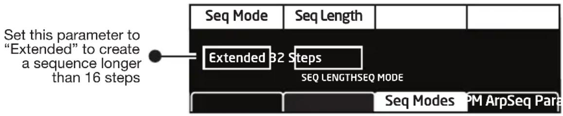
text_image
Set this parameter to "Extended" to create a sequence longer than 16 steps Seq Mode Seq Length Extended 32 Steps SEQ LENGTHSEQ MODE Seq Modes PM ArpSeq ParaEnabling extended sequence mode
To program an extended monophonic note sequence:
- Show the Sequencer mode menu by pressing the ARPEGGIATOR button. If necessary, press the button again to turn off the Arpeggiator
- Press Soft Button 3 (SEQ MODES) to select the SEQUENCER MODE menu.
- Turn Soft Knob 1 and choose EXTENDED.
- Turn Soft Knob 2 and choose the length of the sequence. The maximum length is 64 steps.
- Press the RECORD button and play the desired notes on the keyboard. The numbered step LEDs indicate your current step location. When you cross over into the next 16-step sequence (A,B,C,D) the appropriate LED will light up.
- When you're done, press PLAY to listen to the sequence.
- To save the sequence, save the program by pressing the WRITE button twice.
Paraphonic Sequencing
The Pro 3 can play and sequence 3-note chords when operating in paraphonic mode. In this mode, track 1 is routed to Oscillator 1, track 2 to Oscillator 2, and track 3 to Oscillator 3.

text_image
Play Source Sync to Trk1 Restart Para Seq On OnKeyboard On SYNC TO TRACK 1PLAY SOBSEART PARA SEQ BPM Seq Params Eq Modes Arp Press the Paraphonic button on the front panel to enable this parameter. Then use soft knob 4 to select On.Enabling paraphonic mode
To record a paraphonic sequence:
- Set all three oscillators to the same level in the mixer. You will probably want to set them to the same octave as well.
- Press the PARAPHONIC button to enable paraphonic mode. The Sequencer menu appears in the display.
- Press Soft Button 2 to select the SEQ PARAMS menu.
- Turn Soft Knob 4 (PARA SEQ) and choose ON. Paraphonic sequencing is now enabled.
- Press the RECORD button and play a series of notes and chords on the keyboard. You can play up to 3-note chords. The numbered step LEDs indicate your current step location.
- When you're done inputting notes, press PLAY. Your sequence plays back. To stop playback, press PLAY again.
- To save the sequence, save the program by pressing the WRITE button twice.
Adding Rests, Ties, and Velocity
When recording note sequences using the keyboard, the Sequencer assigns each note that you play (along with its velocity) to successive steps in the sequence. However, you may want to add rests, ties, and additional velocity changes for greater rhythmic variation.
Adding Rests
Rests turn off notes. You can add rests as you record a sequence in real time, or you can add them after you've finished recording.
To add rests in real time as you record:
- Press the RECORD button and play a series of notes.
- When you reach a step where you want to add a rest, press that step LED/button. The step becomes a rest.
- If you want to add several rests in a row, press the step LED/button where you want the rest to end.
-
Continue playing notes as desired to complete the sequence.
-
When you're done, press PLAY. Your sequence plays back. To stop play-back, press PLAY again.
-
To resave the sequence, save the program by pressing the WRITE button twice.

A quick way to add a rest to an already-recorded sequence is to toggle off the front-panel LED/button for that step. The step/button can be toggled on again if you want.
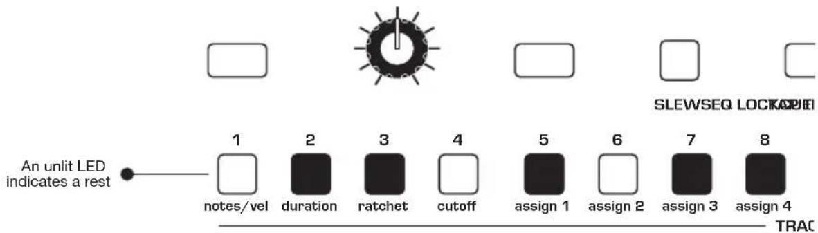
text_image
An unlit LED indicates a rest notes/vel duration ratchet cutoff assign 1 assign 2 assign 3 assign 4 SLEWSEQ LOCKA TRACUnlit LEDs indicate rests (or steps with no notes recorded)
To add rests to an existing sequence using the sequence editor:
-
To show the track in the display, hold down the TRACK SEL button and press the step LED with the same number as the track you want to edit (step 1 = track 1, and so on).
-
Release the TRACK SEL button. The track appears in the display.
-
On the front panel, toggle off the LEDs for the steps that you want to rest. (The step can be toggled on again if you want.) The rest appears as an asterisk (*) in the display.
-
Repeat for any additional steps/rests.
-
To listen to the sequence, press PLAY.

Adding Ties
Ties allow you to increase the duration of a note in a sequence (i.e. the number of steps that it's held). You can add ties as you record a sequence in real time, or you can add them after you've finished recording
To add ties in real time as you record:
- Press the RECORD button and play a series of notes.
- When you reach a step where you want to add a tie, play the note on the keyboard, then press and hold that step LED/button (the LED will be red).
- With that step LED/button still held down, press the step LED/button where you want the tie to end. That series of steps is now tied and the note sustain for that duration.
- Release the buttons.
- Continue playing notes as desired to complete the sequence.
- When you're done, press PLAY. Your sequence plays back. To stop play-back, press PLAY again.
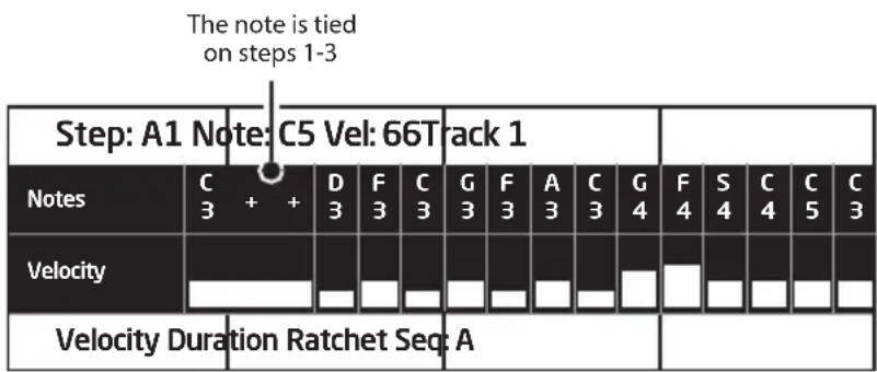
other
| Note | C 3 | + | + | D 3 | F 3 | C 3 | G 3 | F 3 | A 3 | C 3 | G 4 | F 4 | S 4 | C 4 | C 5 | C 3 | |---|---|---|---|---|---|---|---|---|---|---|---|---|---|---|---|---| | Notes | | | | | | | | | | | | | | | | | | Velocity | | | | | | | | | | | | | | | | | | Velocity Duration Ratchet Seq: A | | | | | | | | | | | | | | | | |
LEDs are dimmed on steps that are tied.

Envelope setting and the Sequencer's DURATION parameter may affect how tied sustain.
To add ties to an existing sequence:
- To show the track in the display, hold down the TRACK SEL button and press the step LED with the same number as the track you want to edit (step 1 = track 1, and so on).
- Release the TRACK SEL button. The track appears in the display.
- On the front panel, press and continue to hold the LED button for the step where the tie will start.
- Press the LED button for the step where the tie will end.
- Release the buttons.
- To create additional ties, repeat steps 3-5.
Editing Velocity
When you use the keyboard to record note sequences in real time, the Sequencer records note velocity along with the note values. The sequence editor allows you to edit these values.
To edit velocity on an existing sequence:
-
To show the notes track in the display, hold down the TRACK SEL button and press step LED 1 (NOTES/VEL). Note that if the sequence is paraphonic, tracks 2 and 3 are also note tracks.
-
Release the TRACK SEL button. The notes track appears in the display.
-
Press Soft Button 1 (VELOCITY) to display the velocity parameter for the track.
-
Turn Soft Knob 1 (STEP) to scroll to the desired step.
-
Turn Soft Knob 4 (vel) to edit the velocity value of the selected step.
-
Repeat steps 4 and 5 as desired.

Velocity is only available for editing on note tracks or tracks that have (MIDI)
Out 1 or Out 2 as their destination.

If you have a Sequencer track assigned to a MIDI channel output and it is only ing MIDI note-off messages, check the value of the Velocity parameter for each step.
A velocity greater than zero must be set for a MIDI note-on message to be sent. If the velocity for a given step is set to zero, only a MIDI note-off message will be sent for that step.
Editing Duration
You can use the Sequencer editor to edit the gate duration of notes after you've recorded them. This is useful for creating staccato or legato effects.
To edit duration on an existing sequence:
- To show the notes track in the display, hold down the TRACK SEL button and press step LED 1 (NOTES/VEL). Note that if the sequence is paraphonic, tracks 2 and 3 are also note tracks.
- Release the TRACK SEL button. The track appears in the display.
- Press Soft Button 2 (DURATION) to display the duration parameter for the track.
- Turn Soft Knob 1 (STEP) to scroll to the desired step.
- Turn Soft Knob 4 (DUR) to edit the duration value of the selected step. Lower values create staccato effects. Higher values create legato effects.
- Repeat steps 4 and 5 as desired.
Adding Ratcheting
Ratcheting adds tuplet effects by repeating a note trigger multiple times on the same step. You can choose from 1 to 8 repetitions per step. You may need to adjust envelope settings and a step's DURATION parameter to hear each repetition, depending on the sequence.
To add ratcheting to an existing sequence:
- To show the notes track in the display, hold down the TRACK SEL button and press step LED 1 (NOTES/VEL). Note that if the sequence is paraphonic, tracks 2 and 3 are also note tracks.
- Release the TRACK SEL button. The track appears in the display.
- Press Soft Button 3 (RATCHET) to display the ratchet parameter.
- Turn Soft Knob 1 (STEP) to scroll to the desired step.
- Turn Soft Knob 4 (RCHT) to edit the ratchet value of the selected step.
- Repeat steps 4 and 5 as desired.
Editing Other Elements of a Sequence
You can edit other aspects of a sequence as well, including note values and per-step modulation amounts for any tracks used to modulate synth parameters such as filter cutoff, and so on. This is convenient for fixing mistakes, modifying a sequence, or adding and refining elements of a sequence.
To use the sequence editor:
- Press the SEQUENCE button to select the sequence you want to edit: A, B, C, or D.
- To show the desired track in the sequence editor, hold down the TRACK SEL button and press the step LED with the same number as the track you want to edit.
- Release the TRACK SEL button. The track appears in the display.
To edit notes:
- Make sure track 1 (INITNOTE) is displayed. Then use Soft Knob 1 (STEP) to scroll to the step you want to edit.
- Use Soft Knob 3 (NOTE) to change the note (C0 - G10).
- To re-save the sequence, save the program by pressing the WRITE button twice.
To edit a note's velocity:
- Make sure track 1 (INITNOTE) is displayed. Then use Soft Knob 1 (STEP) to scroll to the step you want to edit.
- Press Soft Button 1 to active the velocity tab, then turn Soft Knob 4 (VEL) to enter a velocity value, 1-127. Turning the knob fully counterclockwise sets the step to REST.
- To re-save the sequence, save the program by pressing the WRITE button twice.

A quick way to edit a step when playback is stopped is to press and hold the step LED for the desired step. You can then edit any parameter for that step while you're at that step location.
To edit a track used for modulation:
- Press the SEQUENCE button to select the sequence you want to edit: A, B, C, or D.
- To show the desired track in the display, hold down the TRACK SEL button and press the step LED with the same number as the track you want to edit.
- Use Soft Knob 1 (STEP) to scroll to the step you want to edit.
- Turn Soft Knob 3 (VAL) to enter a value, 1-127. Most values range from -127 to +127.
- To save the sequence, save the program by pressing the WRITE button twice.
Setting or Changing the Destination of a Track
Each of the four sequences, A,B,C, and D have 16 tracks. Tracks 1-3 are reserved for note-related functions. Tracks 4-16 can be freely assigned.
To set or change the destination of a sequence track:
- Show the desired sequence and track in the display by pressing the SEQUENCE button to select the sequence you want (A, B, C, or D) then holding down the TRACK SEL button and press the step LED with the corresponding track number you want to edit.
- Press and hold the TRACK SEL button and turn Soft Knob 4 to scroll though a list of destinations. Remember that tracks 1-3 are reserved for note-related functions. Tracks 4-16 can be freely assigned.

A quick way to set the destination of a Sequencer track is to hold down the TRACK SELECT button and turn the front-panel knob for the parameter you want to route to that track.
Recording Additional Sequencer Tracks for Modulation
Tracks 4-16 can be freely assigned to any modulation destination. You can either start the Sequencer running and record the modulation values in real time by turning parameter knobs (in which case the Sequencer automatically assigns a track to the edited parameter) or you can input values step by step with the Sequencer stopped.
Here's how to sequence filter cutoff modulation step-by-step.
To modulate filter cutoff frequency using Sequencer Track 4:
- Press and hold the TRACK SEL button then press Sequencer step LED 4. (Alternatively, turn Soft Knob 1 (SELECT TRACK) to select track 4.)
- While continuing to hold down the TRACK SELECT button, turn Soft Knob 4 (DEST) to select CUTOFF.
- Release the TRACK SELECT button.
- Turn Soft Knob 1 to go to the desired step in the sequence
- Turn Soft Knob 3 (VAL) to set a value.
- Repeat steps 4 and 5 for each step in the sequence until finished.
- To listen to the sequence, press PLAY.

If the length of track 1 (notes) is longer or shorter than the modulation tracks in a sequence, you can make all tracks restart to step 1 when track 1 plays step 1 by enabling SYNC TO TRACK 1 in the SEQ PARAMS menu (pres the ARPEGGIATOR button to display this menu).
Using Slew
Slew creates a smooth transition between successive, discrete control voltage levels. You can use slew to create glide effects between note values, a smooth filter cutoff sweep, and so on, depending on the parameter being sequenced.
To add slew to a sequence track:
- Show the desired sequence and track in the display by pressing the SEQUENCE button to select the sequence you want (A, B, C, or D) then holding down the TRACK SEL button and press the step LED with the corresponding track number you want to edit.
- Press the SLEW button. A preset amount of slew is added to the track.
- To hear the effect, press PLAY to start the sequence.
Turning off the Sequencer's "Notes" Track
By design, Sequencer track 1 always controls oscillator frequency, meaning that it is effectively hard-wired for recording notes. However, you may want to use the Sequencer to control other parameters without having it trigger notes. By doing so, you can freely play notes on the keyboard while the Sequencer controls other non-note parameters such as filter cutoff, effect amount, oscillator shape mod, and so on.
To turn off Notes on the Sequencer:
- Create a sequence with parameter automation.
- Press and hold the front panel TRACK SEL button. Track 1 should be displayed by default. If not, continue holding down the TRACK SEL button and press the STEP 1 button/LED.
- Continue to hold down the TRACK SELECT button press Soft Button 3 (NOTES) to set it to OFF.
- Press the front panel MODE button and select GATED.
- Play a series of notes on the keyboard. You'll hear the sequenced parameters change as you play the notes.
Sequencer Parameters (Front Panel)
Track Select: Pressing the button displays the sequence editor. Pressing and holding this button displays various commands for setting track destination, copying a sequence, turning notes on or off, and muting a track. Pressing and holding this button and pressing a step LED selects the corresponding track number and displays it in the sequence editor.
Sequence: A, B, C, D—These buttons select the active sequence.
Record: On, Off—This button turns sequence recording on and off.
Play: On, Off—This button starts and stops sequence playback.
Mode: Normal, Gated, Trigger—This button selects the playback mode. See “Normal, Gated, and Trigger Modes” on page 60 for more details.
Direction: fwd, rev, fwd/rev, random—This button sets the direction of sequence playback.
Reset: Pressing this button switch restarts sequence playback at step 1.
Seq Lock: On, Off—Enabling SEQ LOCK switch keeps the current sequence active while you change programs. In this way you can continue to run the same sequence while recalling different sound programs. If you save a program while using Seq Lock, it will save the sequence to that program and overwrite an existing sequence on that program.
Slew: On, Off—Turning on SLEW creates a smooth transition between the successive, discrete control voltage levels on each sequence step. Use slew to create glide effects between note values, a smooth filter cutoff sweep, and so on, depending on the parameter being sequenced. You can enable Slew individually for each track.
Tap Tempo: 30...250—Tap this button two or more times to quickly set the tempo for the Sequencer and Arpeggiator. The LED flashes at the BPM rate you set. For best results, tap the button 4 times.
BPM: 30...250—Sets the tempo for the Sequencer and Arpeggiator in BPM (beats per minute). When Sync is turned on for an LFO or Delay, the BPM rate affects its LFO frequency or delay time. When syncing to an external MIDI clock source, the BPM setting has no effect.
Divide: Sets the note value for each Sequencer/Arpeggiator step relative to the BPM. DIVIDE works with both internal and external clock sources. The following table lists the DIVIDE values.
| Display Tempo Timing Division | ||
| Half BPM/2 Half note | ||
| Quarter BPM Quarter note | ||
| 8th BPM x 2 Eighth note | ||
| 8 Trip BPM x 3 Eighth note triplets | ||
| 16th BPM x 4 Sixteenth note | ||
| 16th Trip BPM x 6 Sixteenth note triplets | ||
| 32nd BPM x 8 Thirty-second note | ||
| 64th BPM x 16 Sixty-fourth note | ||
Swing: 50%...75%—Adds a variable amount of shuffle-like feel to the master tempo. The greater the amount, the more obvious the effect.
Additional Sequencer Parameters (Display Menus)
Additional Sequencer parameters are found in the menus in the main display. To see these, press the RECORD button on the front panel.

flowchart
graph LR
    A["Keyboard PLAY SOURCE"] --> B["SYNC TO TRK1"]
    B --> C["On RESTART"]
    C --> D["Off PARA SEQ"]
    E["BPM"] --> F["Seq Param"]
    F --> G["Seq Modes"]
    G --> H["Arp"]
The Sequencer Parameters menu
Play Source: Keyboard, Ext In, CV 1, CV 2, CV3, CV4—Selects how the Sequencer is triggered. When set to KEYBOARD, pressing a key on the keyboard control playback. When set to EXT IN, an audio signal connected to the AUDIO IN jack on the back of the Pro 3 will control playback. When set to CV 1, CV2, CV 3, or CV 4, playback is controlled by a control voltage signal connected to the matching control voltage input jack on the back of the Pro 3.
Sync to Track 1: On, Off—When on, restarts all tracks to step 1 when track 1 plays step 1. When off, all tracks play for their respective step lengths.
Restart: On, Off—When the Sequencer is in GATED mode, turning this parameter on restarts the sequence from step one each time you play a note on the keyboard. If this parameter is off, each time you play on a note on the keyboard, the sequence will begin from the most recent point in the sequence.
Para Seq: On, Off—Enables paraphonic sequencing. You can play chords of up to three notes and the Sequencer will record the individual notes to track 1, track 2, and track 3 respectively. Each of these tracks controls the pitch of one of the three oscillators. Paraphonic mode must must be on for this parameter to be available. (Press the front panel PARAPHONIC button.)
Cue Program
Cue Program provides a way to seamlessly switch to another program while the Sequencer continues to play the active sequence. The program will change in perfect sync with the last step of the sequence. The sequence then continues to play using the new, cued program. This also provides a simple way to copy a sequence from one program to another if you resave the cued program once the program and sequence become active.
To use Cue Program:
- Start Sequencer playback.
- Press and hold the CUE PROGRAM button. The bank/ program screen appears.
- While you continue to hold CUE PROGRAM, use the BANK and PROGRAM knobs to select the program you wish to transition to.
- Release the CUE PROGRAM button.
- When track 1 of the Sequencer reaches its final step, the cued program will load and and the sequence will continue to play seamlessly.
- If you want to copy the sequence to the cued program (and overwrite its original sequence) press the WRITE button twice.
Tuned Feedback
Tuned feedback is a method of processing audio using a delay line with tunable feedback. By varying the AMOUNT and TUNING parameters you can use it to create a variety of effects, some subtle, and some industrial-grade nasty, especially if you turn on GRUNGE.
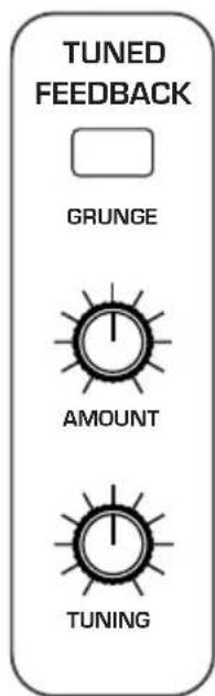
text_image
TUNED FEEDBACK GRUNGE AMOUNT TUNINGThe Tuned Feedback controls
Using Tuned Feedback to Perform "Karplus-Srong" Synthesis
You can also use Tuned Feedback as a tone generator. In classic Karplus-Strong synthesis, a short excitation waveform (white noise) is generated and fed back into a delay line. The output of the delay line is fed into the filter. The filter characteristics determine the harmonic structure of the decaying tone.
To use Tuned Feedback for Karplus-Strong synthesis:
- In the Mixer, set all oscillator levels to zero.
- Set the DESTINATION of Aux Envelope 1 to NOISE.
- Set the AMOUNT of Aux Envelope 1 to 127.
- Set the AUX ENVELOPE 1 ADSR values to the following: ATTACK: 0, DECAY: 45, SUSTAIN: 0, RELEASE: 16.
-
Set the Feedback AMOUNT parameter to 66.
-
Set the Feedback TUNING parameter to 12
- Set the Filter Envelope's ATTACK and DECAY parameters to shape the envelope of the generated sound.
- Experiment with the Feedback AMOUNT parameter and the ADSR parameters of Aux Envelope 1 to shape the harmonic content of the generated sound.
Feedback Parameters
Amount: -127...+127—Sets the level of feedback. As the amount goes up, the feedback will eventually oscillate at the frequency set with the tuning parameter. Medium levels of feedback add depth and movement to the sound.
Tuning: 0...48—Sets the base frequency of the feedback loop. It steps in semitones from C0 to C4 (0-48) for a four octave range. The exact frequency is influenced by factors such as filter cutoff frequency and the number of poles in the filter, which can drive it slightly sharp or flat.
Grunge: On, Off—When on, this enables extreme feedback at higher levels. It has no effect at lower levels of feedback.
Master Volume/Program Volume
The master output level of the Pro 3 is controlled by the front-panel MASTER VOLUME knob. In addition, the volume of an individual program can be set with the VOLUME parameter in the VCA menu. This is useful for ensuring that your sounds have roughly the same volume from program to program.
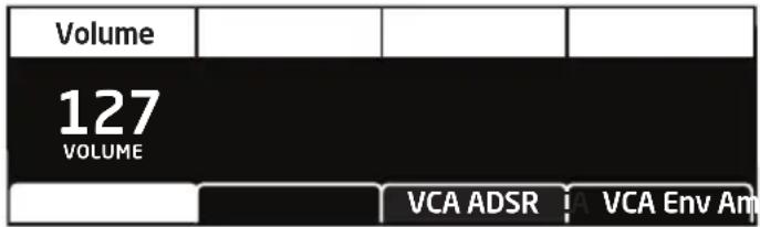
text_image
Volume 127 VOLUME VCA ADSR VA Env AmSetting Program Volume in the Amp Envelope menu
To set the volume of an individual program:
- Choose a program.
- Move any of the AMP ENVELOPE controls on the front panel.
- In the display menu, press Soft Button 1.
- Turn Soft Knob 1 (VOLUME) to adjust the volume level as desired.
- Press the WRITE button twice to save the program.

MIDI volume can also influence the overall volume of the Pro 3 if you are controlling it from an external MIDI source.
Transpose
The UP and DOWN buttons in the TRANSPOSE section transpose the keyboard up or down in octaves. The LED indicates the current keyboard transposition state. Transposing the keyboard also changes the MIDI note numbers of the keys so that MIDI notes sent are also transposed. Transpose settings are global and are not saved with individual programs.

text_image
-2 -1 0 +1 +2 Down Up TRANSPOSEThe Transpose controls
Hold
When HOLD is on, any notes played will continue to play until HOLD is turned off. When used in conjunction with the Arpeggiator, notes are latched on. If HOLD is on and at least one key continuously held down, any new notes played are added to the arpeggio.

The Hold button
Glide
Glide causes the pitch of a note to glide up or down from the pitch of the previously played note. Glide is turned on and off using the GLIDE switch, but the RATE must also be set. If the GLIDE button is on, but RATE is set to 0, glide has no effect. Glide can be set individually for each oscillator.
The Glide button
To use Glide:
-
Press the GLIDE button to turn Glide on.
-
Play a series of notes up and down the keyboard while you turn the GLIDE AMOUNT knob to adjust the amount of glide.
Glide Modes
There are four modes that determine how glide behaves:
Fixed Rate: The time to transition between notes varies with the interval between the notes; the greater the interval, the longer the transition time. The glide rate is fixed. This is the default glide mode.
Fixed Rate A: The same as Fixed Rate, but glide is only applied when playing legato. That is, glide only occurs when a note is held until the next note is played. This effectively allows glide to be turned on and off from the keyboard.
Fixed Time: Glide is set to a fixed time, regardless of the interval between notes.
Fixed Time A: The same as Fixed Time, but glide only occurs when playing legato.
To select a Glide Mode:
-
Press the GLIDE button.
-
In the display menu, use Soft Knob 1 to choose the desired Glide Mode.
-
Play a series of notes up and down the keyboard to hear the effect.
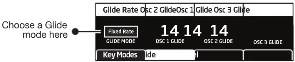
text_image
Choose a Glide mode here Glide Rate Osc 2 Glide Osc 1 Glide Osc 3 Glide Fixed Rate GLIDE MODE 14 14 14 OSC 1 GLIDE OSC 2 GLIDE OSC 3 GLIDE Key Modes slideChoosing a Glide mode
To set the Glide Amount separately for each oscillator:
- Press the GLIDE button.
- Play a series of notes up and down the keyboard while you turn Soft Knobs 1-3 to adjust the amount of glide for individual oscillators.
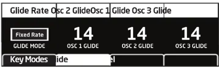
text_image
Glide Rate Osc 2 GlideOsc 1 Glide Osc 3 Glide Fixed Rate GLIDE MODE 14 OSC 1 GLIDE 14 OSC 2 GLIDE 14 OSC 3 GLIDE Key Modes slideGlide parameters
Pitch and Mod Wheels
The Pro 3 has a spring-loaded Pitch wheel and a Mod wheel. You can use these controls to enhance live performance by bending notes and adding modulation in real time as you play.
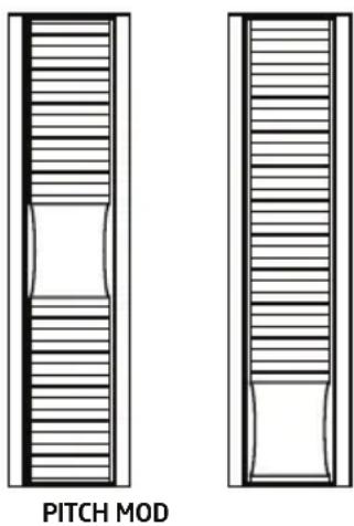
natural_image
Two identical mechanical component diagrams labeled 'PITCH MOD', showing internal structure without any text or symbols.The Pitch and Modulation wheels
Pitch Wheel
You can set a range in semitones for the Pitch wheel, depending on your playing preference. The upward range is 12 semitones (1 octave). The downward range is 24 semitones (2 octaves). Many musicians use a range of 2 semitones (a whole step) since this is the bend range of many acoustic instruments. For guitar whammy bar effects, you many wish to set a wider range.
To set the pitch bend range:
- Press the MISC PARAMS button and press Soft Button 3 (PITCH WHEEL). Button 3
- Use Soft Knob 1 (RANGE UP) to set the range in semitones of the upward bend.
- Use Soft Knob 2 (RANGE DOWN) to set the range in semitones of the downward bend.
- Hold a note and move the Pitch wheel to hear the effect.
Modulation Wheel
The Mod wheel controls the amount of modulation for any program that uses it as a modulation source. This allows you to “perform” modulation in real time by moving the wheel. This is a great way to add expressiveness to a sound or performance by using it to control vibrato, filter effects, and potentially a lot more.
To choose a modulation destination for the Mod wheel:
- In the MODULATION section, press the SOURCE button. Use Soft Knob 1 to scroll to Mod Slot 1 if it's not already displayed.
- Use Soft Knob 2 to scroll through the various mod sources and choose MOD WHEEL.
- Use the Soft Knob 4 to scroll through the various mod destinations and choose a parameter (such as CUTOFF).
- Hold down a note on the keyboard (or press the HOLD button and play a note on the keyboard) and turn the Mod wheel.
- Use the Soft Knob 3 to set the modulation amount to your preference. Higher AMOUNT settings add greater modulation the further you push the Mod wheel. A negative amount setting will apply modulation in the negative direction.

As a shortcut, you can hold down the SOURCE button and move the Mod wheel to quickly assign this modulation path.
| DestinationEdit Mod 1 Source Amount | |||
| Mod 1 | Slider | 60 | Cutoff |
| Mod 2 | LFO 2t | 35 | Osc1 Shape |
| Mod 3 | Aftertouch | 25 | Drive |
| Mod 4 | Mod Wheel | 80 | LFO1 Amt |
| Sort Source | Sort Dest |
Touch slider
The Pro 3 has a position-sensitive Touch slider. Like the Pitch and Mod wheels, you can use this slider to enhance live performance by adding modulation in real time as you play.
The slider serves as a modulation source, the value of which is determined by finger position. The Touch slider appears in the modulation matrix as SLIDER. (See page 120 for a list of mod destinations.)
Normally, the slider affects the assigned modulation destinations only while it's being touched. But when LATCH is on, the Touch slider holds the value from the position at which it was last touched.

text_image
Latch TOUCHThe Touch slider
Use the mod matrix to assign modulation destinations to the slider. You can route multiple modulation destinations to the slider. To display the modulation matrix, press the SOURCE or DESTINATION buttons in the Modulation section. Modulation slots and routings appear in the display.
| DestinationEdit Mod 1 Source Amount | |||
| Mod 1 | Slider | 60 | Cutoff |
| Mod 2 | LFO 2t | 35 | Osc1 Shape |
| Mod 3 | Aftertouch | 25 | Drive |
| Mod 4 | Mod Wheel | 80 | LFO1 Amt |
| Sort Source | Sort Dest |
To assign the slider to a modulation destination:
- On the front panel MODULATION section, press and hold the SOURCE button.
- Touch the slider. The mod matrix appears in the display and SLIDER is assigned to an available modulation slot.
- Turn Soft Knob 4 (DESTINATION) to choose a modulation destination.
- Turn Soft Knob 3 (AMOUNT) to choose the maximum amount of modulation applied when you move your finger to the top range of the slider.
- To route the slider to more destinations, turn Soft Knob 1 (EDIT MOD #) to find an open modulation slot and choose SLIDER.
- Repeat steps 3-4.
Adding Aftertouch
Aftertouch is a performance feature that allows you to add modulation to a sound by applying additional pressure to a key after the key is already down. The greater the pressure applied, the more modulation is applied. The Pro 3 provides monophonic (or “channel”) aftertouch, which means that applying pressure to any key within a paraphonic chord will apply modulation to all notes currently held.
The MODULATION section lets you choose the amount of modulation applied using aftertouch and also which parameters are modulated (oscillator frequency, filter frequency, etc.). You can set either a positive or negative amount.
For example, if you select the filter cutoff as modulation destination (CUTOFF), set a positive amount of pressure, then press a key harder, the filter cutoff frequency will increase, making the filter open wider and the sound become brighter.
Conversely, if you select the filter frequency as destination, set a negative amount of pressure, then press a key harder, the filter cutoff frequency will be lowered, making the filter close more and the sound become more muted.
To choose aftertouch (pressure) as a source for modulation:
- In the MODULATION section, press the SOURCE button. Use the Soft Knob 1 to scroll to Mod Slot 1 if it's not already displayed.
- Use the Soft Knob 2 (SOURCE) to scroll through the various mod sources and choose PRESSURE.
- Use the Soft Knob 4 (DESTINATION) to scroll through the various mod destinations and choose a parameter (such as CUTOFF).
- Hold down a note on the keyboard. Then, press harder.
- Use Soft Knob 3 (AMOUNT) to set the amount to your preference. Higher AMOUNT settings add greater modulation the harder you press a key. A negative amount setting will apply modulation in the negative direction.

The Pro 3 provides four different aftertouch/pressure response settings. The default setting provides a linear response. To choose a different response curve, use the AFTERTOUCH CURVE parameter in the GLOBAL menu.
Distortion
The Pro 3 features analog distortion which can be used to add warmth, harmonic complexity, and an aggressive edge to sounds. The character of the distortion is affected by the harmonic content of a program. Sounds with more high-end will sound different than sounds with fewer harmonics. To add distortion, use the front-panel DISTORTION knob.

DISTORTION
Distortion: 0...127—Sets the distortion amount.
Play List
The Play List enables you to organize programs into lists for quick recall. This feature is particularly useful for live performance where you may want to have specific groups of programs at your fingertips.
Here's how the Play List works:
- There are 10 sets.
• Each set contains 4 Lists.
• Each list contains 4 programs.

flowchart
graph TD
    A["Use Soft Knob 1 to select a program"] --> B["P1"]
    C["Use Soft Knob 2 to select a bank"] --> B
    D["Use Soft Knob 3 to select the List (1-4)"] --> B
    E["Turn Soft Knob 4 to select the Set (1-10)"] --> B
    F["Press Soft Button 1 to select this program within the current List and Set"] --> B
    B --> G["U1 List1 Set1 Prophet Evolution"]
    G --> H["P6U2 P3U4 P5U1"]
The Play List Menu
To create a Play List:
- Press the PLAY LIST button.
- Turn Soft Knob 4 to select SET 1.
- Turn Soft Knob 3 to select LIST 1.
- Press Soft Button 1 to select the first position in the list.
- Use Soft Knob 1 (PROGRAM) and Soft Knob 2 (BANK) to choose the program that you want.
- Press Soft Button 2 to select the second position in the list.
- Use Soft Knob 1 (PROGRAM) and Soft Knob 2 (BANK) to choose the program that you want.
-
Press Soft Button 3 to select the third position in the list.
-
Use Soft Knob 1 (PROGRAM) and Soft Knob 2 (BANK) to choose the program that you want.
-
Press Soft Button 4 to select the forth position in the list.
-
Use Soft Knob 1 (PROGRAM) and Soft Knob 2 (BANK) to choose the program that you want.
-
Now that you have set up List 1. Repeat as desired to set up List 2, List 3, and List 4, if you want.
-
The Lists that you have just created all reside in Set 1. If you want, turn Soft Knob 4 to Set 2 and repeat the entire process to create another 4 lists that will then reside in List 2. You can continue doing this for all 10 sets, if you want.

Play Lists simply point to stored Factory or User programs. Editing and saving a program changes that program in memory and, as a result, in any Play Lists in which it appears. If you need a program to behave differently in different situations, save multiple copies of the program edited and named appropriately for each situation.

To export Play Lists as MIDI SysEx data, use DUMP PLAYLISTS command in the Global menu with a computer and MIDI utility such as SysEx Librarian. All Play List data will be exported as a SysEx file.
To recall programs from a Play List:
-
Press the PLAY LIST button.
-
Turn Soft Knob 4 to select the Set you want (1-10).
-
Turn Soft Knob 3 to select the List you want (1-4).
-
Use Soft Buttons 1-4 to choose the program you want within the currently selected Set and List.
Miscellaneous Parameters
Pressing the MISC PARAMS button displays the miscellaneous parameters menu. Here you'll find settings for Key Modes, Gate Source, Alternate Tunings, Glide, and the Pitch Wheel.
To use the MISC PARAMS menu:
- Press the MISC PARAMS button.
- Use Soft Buttons 1-3 to select the desired menu.
- Use Soft Knobs 1-4 to set a selected parameter.
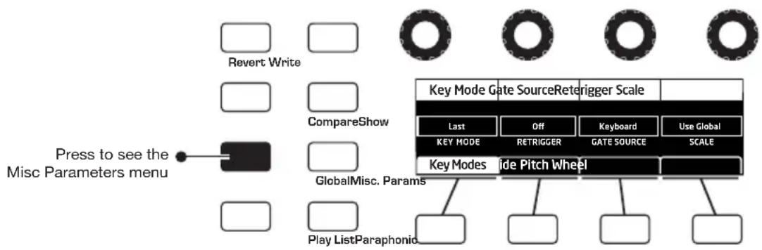
flowchart
graph TD
    A["Revert Write"] --> B["CompareShow"]
    B --> C["Press to see the Misc Parameters menu"]
    D["Play ListParaphonic"] --> E["Play ListParaphonic"]
    F["Key Mode Gate Source Retrorigger Scale"] --> G["Last"]
    F --> H["Off"]
    F --> I["Keyboard"]
    F --> J["Use Global"]
    F --> K["KEY MODE"]
    F --> L["RETRIGGER"]
    F --> M["GATE SOURCE"]
    F --> N["SCALE"]
    O["Key Modes"] --> P["ide Pitch Wheel"]
    Q["GlobalMisc. Params"] --> P
    style A fill:#fff,stroke:#000
    style D fill:#fff,stroke:#000
    style F fill:#fff,stroke:#000
    style O fill:#fff,stroke:#000
    style P fill:#fff,stroke:#000
    style Q fill:#fff,stroke:#000
Key Modes Tab
Key Mode (sometimes called note priority) determines what note has priority when more than one note is played on the keyboard or via MIDI.
- Low (note) Priority is most common in vintage synths and is often used for playing trills by holding a note and repeatedly tapping a lower note.
- Low (note) Retrigger causes the envelopes to be retriggered with each keystroke.
- High (note) and High Retrigger are similar to the low note settings, except that the highest note is given priority.
- Last (note) and Last Retrigger give priority to the last note played.
Key Mode: Low Note, High Note, Last Note—(In the KEY MODES tab) Selects the key priority when more than one key is played simultaneously. LOW NOTE, HIGH NOTE and LAST NOTE are monophonic playback modes that give priority to the lowest, highest, or last note played, as their names imply.
Retrigger: On, Off—(In the KEY MODES tab) Determines whether or not the envelopes are retriggered if a note is held while additional notes are played.
Gate Source
Gate Source determines the source that triggers the Pro 3's envelopes.
Keyboard: Selects normal envelope triggering using the Pro 3 keyboard.
ExtAudio: Selects envelope triggering using an external audio source connected to the audio in connector on the rear of the Pro 3.
Scale
By default, the Pro 3 is set to standard, chromatic western tuning. Additionally, it supports 64 additional, alternative tunings. These range from Indonesian Gamelan tunings to even more esoteric modes. To select an alternative turning, use Soft Knob 4 to scroll through the SCALE menu. For descriptions of the included tunings, see page 130.

Alternative tunings can be enabled on a per-program basis here, or globally for all programs by using the SCALE parameter in the GLOBAL menu.
Glide Tab
As explained previously, Glide causes the pitch of a note to glide up or down from the pitch of the previously played note. Glide is turned on and off using the GLIDE switch, but the RATE must also be set. If the GLIDE button is on, but RATE is set to 0, glide has no effect.
Glide can be set individually for each oscillator.
Glide Mode: FixRate, FixRate A, FixTime, FixTime A—(In the KEY MODES tab) These modes determine how GLIDE behaves:
FixRate: The time to transition between notes varies with the interval between the notes; the greater the interval, the longer the transition time. The glide rate is fixed.
FixRate A: The same as FixRate, but glide is only applied when playing legato. That is, glide only occurs when a note is held until the next note is played. This effectively allows glide to be turned on and off from the keyboard.
FixTime: Glide is set to a fixed time, regardless of the interval between notes.
FixTime A: The same as FixTime, but glide only occurs when playing legato.
Pitch Wheel Tab
You can set a range in semitones for the Pitch wheel, depending on your playing preference. The range is 12 semitones up (1 octave) and 24 semitones down (2 octaves).
Range Up: Off, 1...12 Semitones—(In the PITCH WHEEL tab) Selects the range in semitones when bending the Pitch Wheel upward. Twelve semi-tones equals 1 octave.
Range Down: Off, 1...24 Semitones—(In the PITCH WHEEL tab) Selects the range in semitones when bending the Pitch Wheel downward. Twenty-four semitones equals 2 octaves.
Global Settings
The GLOBAL menu is where you'll find settings that apply to the synthesizer as a whole — in other words, settings that apply to the overall behavior of the synth. These include such things as master tuning, keyboard velocity curves, MIDI settings, Pitch and Mod wheel calibration, and more.

You can use the GLOBAL button to set the program that appears when you power on the Pro 3. Simply use the BANK and PROGRAM knobs to find the program you want, then press the GLOBAL button twice. That program is now the default program on start up.
To use the GLOBAL menu:
- Press the GLOBAL button.
- Use Soft Knob 1 to scroll through the list of parameters.
- To set a selected parameter, turn Soft Knob 3 or press Soft Button 1, as necessary.
Here are descriptions of all of the GLOBAL menu parameters.
- Master Coarse Tune: -12...+12—Master Transpose control; a setting of 0 is the equivalent of concert pitch. This control steps in semitones one octave up (+12) or down (-12).
- Master Fine Tunet: -50...+50—Master Fine Tune control; 0 centered. Steps in cents as much as a quarter-tone up (+50) or down (-50).
- MIDI Channel: All, 1...16—Selects which MIDI channel to send and receive data, 1 to 16. Choosing ALL receives on all 16 channels.
- MIDI Clock Mode: Sets the synthesizer's ability to send and receive MIDI clock messages:
• OFF: MIDI Clock is neither sent nor received
- MASTER: MIDI Clock is sent, but not received.
- SLAVE: MIDI Clock is received, but not sent.
• SLAVE THRU: MIDI Clock is received and passed to MIDI Out
- SLAVE NO S/S (no start and stop): Receives MIDI Clock but does not respond to MIDI Start or Stop command.

In SLAVE and SLAVE THRU modes, if no MIDI clock is present at the selected input, the Arpeggiator and Sequencer will not function.
-
MIDI Clock Cable In: MIDI Port, USB—Sets the port (MIDI or USB) by which MIDI clock is received.
-
MIDI Clock Cable Out: MIDI 1, MIDI 2, USB, MIDI ALL, ALL—Sets the port by which MIDI clock is sent.
-
MIDI Param Send: Off, CC, NRPN—Changes to the values of front panel controls are transmitted via MIDI as Non-registered Parameter Number (NRPN) controllers or as Continuous Controllers (CC). Transmission of parameters can also be turned off.

NRPNs are the preferred method of parameter transmission, since they cover the complete range of all parameters, while CCs are limited to a range of 128.
-
MIDI Param Receive: Off, CC, NRPN—Sets the method by which parameter changes are received via MIDI. As with transmission, NRPNs are the preferred method.
-
MIDI Control Enable: Off, On—When On, the synth will respond to MIDI controllers, including Pitch Wheel, Mod Wheel, Pedal, Breath, Volume, and Expression.
-
MIDI Sysex Enable: On, Off—Sets whether MIDI System Exclusive data will be received or ignored.
-
MIDI Sysex Cable: None, MIDI Port, USB—Sets the port, MIDI or USB, by which System Exclusive data will be transmitted and received.
-
MIDI Out Select: Off, MIDI 1, MIDI 2, USB, MIDI All, All—Sets the port(s) by which MIDI data will be transmitted.
-
MIDI Program Send: Off, On—When On, the synth will transmit MIDI Program Change and other SysEx messages to the MIDI Out.
-
MIDI Program Receive: Off, On—When On, the synth will respond to received MIDI Program Change and other SysEx messages.
-
MIDI Arp Notes: Off, On—When On, the synth's Arpeggiator outputs MIDI note numbers. You can use this feature to drive other MIDI-equipped devices such as synthesizers and drum machines.
-
Arp Beat Sync: Off, Quantize—When set to QUANTIZE, Arpeggiator note playback occurs only on the beat, regardless of when you press a key on the keyboard.
-
Local Control: All Off, Key/Wheels Off, On—When on (the default), the keyboard and front panel controls directly affect the Pro 3. When off, the controls are transmitted via MIDI but do not directly affect the “local” synth (that is, the Pro 3). When KEY/WHEELS OFF is selected the front controls are enabled (so that you can edit them) but the keyboard and Pitch/Mod wheels are off. This is primarily useful for avoiding MIDI data loops that can occur with some external Sequencers.
-
Mono/Stereo: Stereo, Mono—The Pro 3 defaults to stereo operation. When set to Mono, this parameter defeats all pan settings and modulation, effectively making each of the outputs a mono output.
-
Pot Mode: Relative, Passthru, Jump—The rotary controls on the Pro 3's front panel are a mixture of “endless” rotary encoders and potentiometers or “pots.” The pots are identifiable by their lined knobs and limited amount of travel. There are three pot modes to determine how the synth reacts when the programmable parameters are edited. (Master volume is not programmable, so these modes don’t apply.)
When set to RELATIVE, changes are relative to the stored setting. In Relative mode, the full value range is not available until either the minimum or maximum value and the respective lower or upper limit of the pot's travel is reached.
For example, the Resonance parameter has a value range of 0 to 254. Let's say the physical position of the Resonance pot is the equivalent of a value of 200. If you switch to a program that has a stored Resonance setting of 63 and turn the pot all the way up, it will only go to 117. To get to the maximum value of 255, you first have to turn down until the value is at the other extreme and the pot is at the limit of its travel (in this case, 0 and fully counter-clockwise, respectively).
In PASSTHRU mode, turning the pot has no effect until after the edited value equals the preset value (that is, until the edited value “passes through” the stored value).
JUMP mode uses an absolute value based upon the position of the pot when edited: turn a pot and the value jumps immediately from the stored value to the edited value.
-
Footswitch Polarity: Normal, Reversed—There are two types of momentary footswitches, normally open and normally closed. Either type can be used with the Sustain switch input. This setting allows you to accommodate both models in case yours behaves in a way that is the opposite of what you expect due to its polarity. (Sustain is on until the footswitch is pressed and then it turns off, which is the opposite of the expected behavior.) Connect your pedal and choose the appropriate setting based on its behavior.
-
Footswitch Function: Sustain, Arp Hold, Arp Hold Mom—Sets the function for the Sustain pedal input the rear of the synthesizer. Selecting SUSTAIN chooses normal sustain pedal operation. Selecting ARP HOLD and pressing the sustain pedal causes the Arpeggiator to hold the current arpeggio as if you had pressed the hold button on the front panel. Selecting HOLD MOM causes the Arpeggiator to sustain (even when you release the notes on the keyboard) for as long as you hold down the pedal. Releasing the Sustain pedal stops the Arpeggiator.
-
Pedal Polarity: Normal, Reversed—There are two types of pedals, normally open and normally closed. Either type can be used with the Sustain switch input. This setting allows you to accommodate both models in case yours behaves in a way that is the opposite of what you expect due to its polarity. Connect your pedal and choose the appropriate setting based on its behavior.
-
Pedal Function: LPF Full, LPF Half—When you use an expression pedal connected to the PEDAL jack to control filter cutoff, this sets the range of modulation sent. With LPF FULL selected, an expression pedal connected to the FILTER jack will control filter cutoff frequency within its full range of 0-1019 (fully closed to fully open). With LPF HALF selected, an expression pedal connected to the FILTER jack will control filter cutoff frequency within half of its range (fully closed to half open).
-
Aftertouch Enable: On, Off—Selects whether aftertouch (key pressure) is enabled or disabled. If disabled, the Pro 3 will neither respond to nor transmit aftertouch/key pressure data.
-
Aftertouch Curve: Curve 1, Curve 2, Curve 3, Curve 4—Sets one of four pressure curves for the keyboard to adjust the aftertouch to your playing style.
-
Velocity Curve: Curve 1... Curve 8—Sets one of the eight velocity curves for the keyboard to adjust the velocity response to your playing style.
-
Scale (Alt Tuning): Equal Temperment, 1...17—Selects one of the Pro 3's built-in tunings. Set to 1. EQUAL TEMPERMENT, the tuning is standard, chromatic tuning. Choosing 2 through 65 selects an alternative, non-chromatic, non-Western scale that can be used to emulate ethnic instruments or in other creative ways. See “Appendix C: Alternative Tunings” on page 82 for a description of each tuning. Additional tunings can be imported as a SysEx message. Note that alternative tunings can be enabled globally here, or on a per-sound basis by using the SCALE parameter in the KEY MODES tab of the MISC PARAMS menu.
-
CV 1 In Offset: -127...+128—Allows adjustment of the DC offset of control voltage input 1.
The Pro 3 is flexible when it comes to Control Voltages, and it can be configured to accurately interact with virtually all Eurorack modules. The Pro 3's CV inputs and outputs have a range of 0 to 10v. Since the range is 0-10v, Middle C is sent from the CV output at 5v. This allows the CV out to track over a 10 octave range, from 0 to 10v. There is no standard input voltage range for Eurorack modules. Some modules and external synthesizers have a 10v input range, while others have a 5v input range. For example, if you want a 0-5v range, set offset to 64.
Using the CV OFFSET parameter, you can configure the Pro 3 as necessary to work correctly with your specific module. You can also assign the keyboard and Sequencer of the Pro 3 to transmit CV data at 1v/octave by assigning NOTE NUMBER to modulate CVs 1-4 OUT with an Amount of 127 in the Mod Matrix.
-
CV 2 In Offset: -127...+128—Allows adjustment of the DC offset of control voltage input 2.
-
CV 3 In Offset: -127...+128—Allows adjustment of the DC offset of control voltage input 3.
- CV 4 In Offset: -127...+128—Allows adjustment of the DC offset of control voltage input 4.
- CV 1 In Scale: -127...+128—Allows adjustment of the input scale of control voltage input 1.
The Pro 3's oscillators can both drive and be driven by control voltages. Because the electronics in any device are rarely perfect, CV In and Out scaling allows you to make slight adjustments so that the Pro 3 and any connected CV devices are in tune with each other.
- CV 2 In Scale: -127...+128—Allows adjustment of the input scale of control voltage input 2.
- CV 3 In Scale: -127...+128—Allows adjustment of the input scale of control voltage input 3.
- CV 4 In Scale: -127...+128—Allows adjustment of the input scale of control voltage input 4.
- CV 1 Out Offset: -127...+128—Allows adjustment of the DC offset of control voltage output 1.
- CV 2 Out Offset: -127...+128—Allows adjustment of the DC offset of control voltage output 2.
- CV 3 Out Offset: -127...+128—Allows adjustment of the DC offset of control voltage output 3.
- CV 4 Out Offset: -127...+128—Allows adjustment of the DC offset of control voltage output 4.
- CV 1 Out Scale: -127...+128—Allows adjustment of the output scale of control voltage output 1.
-
CV 2 Out Scale: -127...+128—Allows adjustment of the output scale of control voltage output 2.
-
CV 3 Out Scale: -127...+128—Allows adjustment of the output scale of control voltage output 3.
- CV 4 Out Scale: -127...+128—Allows adjustment of the output scale of control voltage output 4.
- Screen Saver: On, Off—The Pro 3 display has a built-in screen saver that puts it to sleep when not in use. This features is designed to prolong the life of the display and we recommend using it. If, however, you want to disable this feature you can do so by setting it to OFF.
- Basic Program—Press WRITE NOW (Soft Button 1) to load a basic, template program into the edit buffer. Press the WRITE button to save it to memory. As a shortcut, press the TRANSPOSE DOWN and LATCH buttons simultaneously.
- Calibrate Wheels—Calibrates the Pitch and Mod wheels.
- Calibrate VCO's & Filters—Calibrates the voltage controlled oscillators and filters. You shouldn't need to do this under most circumstances since the oscillators and filters are calibrated at the factory and generally don't require re-calibration or re-tuning.
- Reset Globals—Sets the global parameters to the factory default settings.
- Dump Current Program—Transmits the current program in SysEx format via the selected MIDI port. Dumped programs will load back into the same location in memory when imported back into the synth via MIDI.
-
Dump Current Bank—Transmits the current bank in SysEx format via the selected MIDI port. (See MIDI Sysex Cable on page 97.) Dumped banks will load back into the same location in memory when imported back into the synth via MIDI.
-
Dump All User Banks—Transmits all four User Banks and Play Lists in SysEx format via the selected MIDI port. (See MIDI Sysex Cable on page 97.) Dumped banks will load back into the same location in memory when imported back into the synth via MIDI.
- Dump Playlists—Transmits all Play Lists in SysEx format via the selected MIDI port. (See MIDI Sysex Cable on page 97.) You may want to do this in order to archive Play Lists or transfer them to another Pro 3 that has the same set of User Programs.
Chapter 3: Programming the Pro 3
The Pro 3 can produce a vast spectrum of sounds. While the factory programs give you some idea of its scope, if you only make use of its presets, you're not really using the Pro 3 to its full potential. The real excitement is in creating sounds that are uniquely your own.
This chapter provides some brief tutorials. While there isn't enough space here to cover how to use every Pro 3 function, the examples will help you get familiar with some basic concepts. Making sounds you've never heard before can be very rewarding.
Synthesis 101: Synth Bass
Some of the best synth bass sounds consist of a single oscillator, a bit of filter resonance, the right envelope, and not much else. So start with the Basic Program and go from there.
Short Version
To create a classic synth bass:
- Press the GLOBAL button.
- Use Soft Knob 1 to navigate to BASIC PROGRAM and press Soft Button 1 (WRITE NOW).
- Set filter CUTOFF to 40 (refer to the main display).
- Set filter RESONANCE to 100.
- In the ENVELOPES section, set the Filter Envelope's ENV AMOUNT to 50.
- Play a low note on the keyboard. Instant synth bass!
- Experiment with the Filter Envelope's ENV AMOUNT and DECAY settings.
Long Version with Explanations
Here's a more detailed version that provides insight into the process. You'll start with the Basic Program, then learn how to choose an appropriate oscillator waveshape, how to use the filter, how to use the envelopes, and how to use Unison to fatten things up.
In the Basic Program, only Oscillator 1 is audible. Its waveshape is set to sawtooth and its level is 127 in the MIXER. (Oscillator 2 and Oscillator 3 levels are set to zero.)
To start with the Basic Program:
- Press the GLOBAL button.
- Use Soft Knob 1 to navigate to the BASIC PROGRAM command, then press Soft Button 1 (WRITE NOW).
Each of the waveforms have their own unique sound:
- The sawtooth waveform is a good starting point for sounds because it has plenty of harmonics. This gives you a lot to work with in terms of a raw sound that you can filter and modulate.
- The pulse (square) wave is a good starting point, too, but sounds different than the sawtooth, because of its different harmonic content. The sawtooth has even-numbered harmonics and the square wave has odd-numbered harmonics. (Google this if you want to learn more.)
- The sine wave has no harmonics. It's useful used alone for its pure tone, or in combination with another oscillator or sample(s) to reinforce the fundamental pitch of a sound and add weight.
- On Oscillator 3, the super sawtooth is a stacked version of the sawtooth and sounds very thick when you use the SHAPE MOD knob to detune it. It's great for brass, strings, and classic dance music sounds.
To listen to the various oscillator waveshapes:
-
In the OSCILLATORS section, the Sawtooth waveform is selected by default. Play and hold a note, then turn the SHAPE knob to step through the various waveshapes.
-
Select the sawtooth waveshape.
Next, you'll use the filter to shape the raw sound of the sawtooth wave.
To adjust the filter:
-
Press and hold down a key and turn the filter's CUTOFF knob. Notice how it cuts the high frequencies as you rotate counter-clockwise, making the sound of the oscillator less bright. If you turn the CUTOFF knob fully counterclockwise you'll filter out all frequencies and hear nothing.
-
Return the CUTOFF knob to its halfway position, play and hold a note again then turn the RESONANCE knob about halfway up. Notice how the sound changes as a band of frequencies near the cutoff is amplified.
-
Rotate the filter's CUTOFF knob again and you'll hear a classic resonant filter sweep. You're going to use this to create your synth bass.
-
Set the filter CUTOFF to a value of 40 (refer to the main display to see its numeric value).
-
Set the filter RESONANCE to a value of 100. This is going to give the synth bass its funky “zap.”
-
Play a note and listen to the sound. At this point you won't hear anything because you've mostly closed the filter. You'll need to open the filter using the filter envelope (so you don't have to turn the CUTOFF knob by hand).
Now, you'll use the filter envelope to control the filter sweep.
To adjust the filter envelope:
-
In the Envelopes section, turn the Filter Envelope's AMOUNT knob to a value of 50 (refer to the main display to see its numeric value).
-
Play a low note on the keyboard. Instant synth bass!
Notice how the sound has changed. The Filter Envelope is controlling filter cutoff by the amount you set with the AMOUNT knob.
-
Continue experimenting with the Filter Envelope's AMOUNT knob. Notice how greater AMOUNT settings amplify the effect of the envelope on the filter.
-
Repeatedly strike a note on the keyboard as you turn the Filter Envelope's DECAY knob clockwise and counterclockwise. Notice how it changes the sound as the note decays faster or slower.
Be aware that the Filter Envelope and Amplifier Envelope work in conjunction, with the Filter Envelope controlling how the filter opens and closes and the Amplifier Envelope controlling the overall volume shape. To learn more about the Amplifier Envelope, see page 35
- The Filter Envelope's RELEASE parameter acts in conjunction with the Amplifier Envelope. In other words, you can't hear a long release on the filter envelope if the amplifier envelope is short! So to hear the filter envelope's RELEASE parameter in action, first set the Amp Envelope's RELEASE value to 75.
- Now repeatedly strike a note on the keyboard as you turn the Filter Envelope's RELEASE knob clockwise and counterclockwise. Notice how the note fades out faster or slower as you change the RELEASE value.
Now you know how to create a simple synth bass program using the most essential synthesizer components of the Pro 3: the oscillators, the filters, and the envelopes. Using just these three things you can create an enormous variety of sounds. Keep experimenting with them and if you like what you’ve created, save the programs in one of the user banks. (See “Saving a Program” on page 10.)
Creating Synth Brass
Here's another easy-to-construct sound: synth brass, with a classic “pitch blip” effect on the attack. In this example you’ll learn how to detune the super saw wave, and how to use an auxiliary envelope to modulate the pitch of oscillator 2 to simulate an aggressively blown horn effect.
To create synth brass:
- Press the GLOBAL button.
- Use Soft Knob 1 to navigate to BASIC PROGRAM and press Soft Button 1 (WRITE NOW). As a shortcut, hold down the front-panel TRANSPOSE DOWN button and press the HOLD button.
- In the mixer, turn up Oscillator 2 to 127. (Osc 1 is already at 127.)
- In the OSCILLATORS section, set both oscillators to the sawtooth wave and osc 2 PITCH to -5 to detune and thicken them.
-
In the display press Soft Button 2 to select the oscillator SHAPE menu then use Soft Knob 4 to set OSC SLOP to 10 to add extra oscillator drift.
-
In the FILTER section, set CUTOFF to 26, RESONANCE to 15, and DRIVE to 100.
-
In the FILTER ENVELOPE section, set the AMOUNT to 105, the ATTACK to 17, DECAY to 64, SUSTAIN to 50, and RELEASE to 90.
-
Enable touch sensitivity by pressing and enabling the VELOCITY button.
-
In the AUXILIARY ENVELOPE section, select ENVELOPE 1 and set its destination to osc 2 COARSE FREQ. This routes envelope 1 to modify Osc 2 pitch according to its ADSR (attack, decay, sustain, release) settings. This will create the slight pitch variation at the beginning of the sound (the "pitch blip").

You can quickly assign the mod destination for Envelope 1 by holding down the envelope's selector button and turning the Oscillator 2 frequency knob. This will auto-assign the modulation destination to the envelope.
-
Set the auxiliary AMOUNT to 35 and DECAY to 20.
-
Play some notes in the upper range of the keyboard. Classic synth brass!
-
Experiment with different auxiliary envelope AMOUNT and DECAY settings to fine tune the “pitch blip” effect.
Turning Synth Brass into a Paraphonic String Pad
It's a simple matter to turn the previous synth brass sound into a string pad by simply adjusting its envelope and filter settings.
To turn the synth brass into a string pad:
-
Enable Paraphonic mode by pressing the paraphonic button on the front panel.
-
Turn up the level of Oscillators 1, 2, and 3 to 127.
-
Set all three oscillators to a sawtooth wave. And set their OCTAVE to 2.
-
In the FILTER section, set the CUTOFF to 800 and RESONANCE to 122.
-
In the FILTER ENVELOPE section, set the ENV AMOUNT to 12.
-
Set filter envelope ATTACK to 59, DECAY to 75, SUSTAIN to 67, and RELEASE to 71.
-
Set amplifier envelope ATTACK to 66, DECAY to 62, SUSTAIN to 124, and RELEASE to 80.
- Play some chords. You've now got a good basic string pad.
Adding Effects to the String Pad
You can enhance the string pad adding an effect such as chorus and phas-ing for a retro feel.
To add effects to the string pad:
- In the EFFECTS section, press the EFFECT 1 button.
- Turn the EFFECT TYPE knob and choose CHORUS.
- Set MIX to 62, then set parameter 1 (DEPTH) to 131, parameter 2 (RATE) to 40, and parameter 3 (LPF CUTOFF) to 127.
- Play some chords. Classic string machine! For a retro 70's era string synth, let's add the phaser.
- Press press the EFFECT 2 button.
- Turn the EFFECT TYPE knob and choose PHASER.
- Set MIX to 64, then set parameter 1 (DEPTH) to 179, parameter 2 (RATE) to 15, and parameter 3 (FEEDBACK) to 255.
- Play some chords. Retro string machine! For even more dramatic phasing, set MIX to 127.
Creating a Hard-Sync Lead
Here's another classic sound: a hard-sync lead. A famous example of this is “Let’s Go” by the Cars (performed on a Prophet-5). In this example you’ll learn how to hard-sync the oscillators, pitch-modulate one of them with an auxiliary envelope, then add effects.
To create a hard-sync lead:
- Press the GLOBAL button.
- Use Soft Knob 1 to navigate to BASIC PROGRAM and press Soft Button 1 (WRITE NOW). As a shortcut, hold down the front-panel TRANSPOSE DOWN button and press the LATCH button.
- In the mixer, turn up Oscillator 2 to 127. (Osc 1 is already at 127.)
- In the OSCILLATORS section, set both oscillators to sawtooth.
- On Oscillator 1, enable the SYNC 1 button. (See page 19 for an explanation of hard sync.)
- Set Oscillator 1's OCTAVE to 1. This will allow for a wide range of pitch modulation in step 9.
- In the AUX ENVELOPE section, select ENVELOPE 1.
- In the display, press Soft Button 1 (AUX 1 DEST) and use Soft Knob 1 to choose osc 1 COARSE FREQ as the destination. This routes envelope 1 to modulate Oscillator 1 pitch according to its ADSR (attack, decay, sustain, release) settings.
- Set the auxiliary ENV AMOUNT to 127 and ATTACK to 23, DECAY to 60, SUSTAIN to 100, and RELEASE to 65. This will set the amount and “shape” of the modulation.
- Play some notes. Classic hard-sync lead!
- Experiment with Aux Envelope 1's Attack, Decay, Sustain, and Release settings to better understand how these affect the shape of pitch modulation routed to Oscillator 1.
Adding Effects to the Lead
You can enhance the sync lead by adding some delay and reverb.
To add effects:
- In the EFFECTS section, press the EFFECT 1 button.
- Turn the EFFECT TYPE knob and select DELAY STEREO.
- Set MIX to 30, then set parameter 1 (TIME) to 135, parameter 2 (FEEDBACK) to 20, and parameter 3 (LPF) to 100.
- In the EFFECTS section, press the EFFECT 2 button.
- Turn the EFFECT TYPE knob and select SUPER PLATE.
- Set MIX to 30, then set parameter 1 (TIME) to 100, parameter 2 (TONE) to 138, and parameter 3 (PREDELAY) to 12.
- Play some notes. Perfect hard-sync lead!
A Final Word
The examples given in this chapter are fairly basic, but they give you some idea of the power of synthesis. Imagine what you can create by using these as starting points, then modulating the filters, oscillators, and even effects with LFOs, Auxiliary Envelopes, the Sequencer, and other modulation sources.
It's often useful to start with a simple sound and make it progressively more complex, saving edited versions as you go so that you can retrace your steps and branch off at different points in the sound design process if you want.
We wish you many enjoyable hours of experimentation!
Chapter 4: Using the Pro 3 with External Devices
This chapter explains how to use the Pro 3 to process external audio, how to synchronize the Pro 3's Sequencer to an external MIDI device, and how to use the Pro 3 with a modular synthesizer.
Processing External Audio
The Pro 3 makes a great effects processor. The example below shows you how connect external audio to the Pro 3 and process it in real time by tweaking knobs and controls.

To hear an external audio signal, you need to gate the amplifier and filter open.
When you do this, you will also hear the Pro 3's oscillators droning since they're continuously producing sound. To avoid continuous oscillator drone, set the LEVEL of all oscillators to zero in the Mixer.
To process external audio:
- Connect an instrument or audio signal to the AUDIO IN jack on the rear of the Pro 3 and turn up the instrument to a suitable level.
- Press the HOLD button then play a key on the keyboard. This holds the VCA open.
- To avoid continuous oscillator drone, set the LEVEL of all oscillators to zero in the Mixer.
- Turn up the EXT AUDIO knob in the Mixer section of the Pro 3. (If you need to further boost the signal, adjust INPUT LEVEL and INPUT GAIN. When you adjust the EXT AUDIO knob in the mixer, these controls appear in the display.
- Turn the SUSTAIN knob on the amplifier envelope to 127.
- Turn the SUSTAIN knob on the filter envelope to 127.
- Play the external audio source.
- Tweak parameters such as filter cutoff, distortion, drive, tuned feedback, effects, and so on to process the sound.
Filtering External Audio Using the Envelope Follower
The Pro 3's envelope follower makes it easy to process external audio with an “auto-wah” type effect. Add a little distortion and delay and this is a very expressive effect.
The Envelope Follower has controls for ATTACK and RELEASE in the EXT IN ENV tab. Display these parameters by turning the EXT AUDIO knob in the Mixer.

other
| Input Level | Input Gain In Gat Thresh | Input Gain In Gat IN GAIN | | :--- | :--- | :--- | | 80 | 99 | 25 | | INPUT LEVEL | INPUT GAIN | IN GATE THRESH | | Mixer | n | Ext In Env || Input Attack Input Release | ||
| 80 INPUT ATTACK 99 INPUT RELEASE | ||
| Mixer Ext In | ||

To avoid continuous oscillator drone, set the OUTPUT LEVEL of all Pro 3 oscillators.
To filter external audio with the envelope follower:
- Connect an instrument or audio signal to the AUDIO IN jack on the rear of the Pro 3 and turn up the instrument to a suitable level.
- Press the HOLD button then play a key on the keyboard. This holds the VCA open.
-
To avoid continuous oscillator drone, set the LEVEL of all oscillators to zero in the Mixer.
-
Turn the SUSTAIN knob on the amplifier envelope to 127.
-
Turn the SUSTAIN knob on the filter envelope to 127.
-
Press the SOURCE button in the Modulation section.
-
With Soft Knob 2 (SOURCE) choose ENV FOLLOW as the source.
-
With Soft Knob 4 (DESTINATION) choose ENV VCA AMT as the destination.
-
With Soft Knob 1 (EDIT MOD) choose a second available mod slot.
-
With Soft Knob 2 (SOURCE) choose ENV FOLLOW as the source.
-
With Soft Knob 4 (DESTINATION) choose CUTOFF as the destination.
-
Use Soft Knob 3 to adjust the modulation AMOUNT for both modulation routings. Try a setting of +120 for the ENV VCA AMOUNT parameter and a setting of +90 for the CUTOFF parameter.
-
Play the external audio source.
-
Turn up the EXT AUDIO knob in the Mixer section of the Pro 3. (If you need to further boost the signal, adjust INPUT LEVEL and INPUT GAIN. When you adjust the EXT AUDIO knob in the mixer, these controls appear in the display.
-
Set the IN GATE THRESH to 100. You can adjust this later if necessary.
-
As the external audio source continues to play, show the Envelope Follower's ATTACK and RELEASE parameters in the display by turning the EXT AUDIO knob in the mixer. Try an ATTACK setting of 5 and RELEASE setting of 38.
-
Adjust the front panel filter CUTOFF and RESONANCE parameters. Try a CUTOFF setting of 0 and RESONANCE setting of 160.
-
Adjust any other parameters such as distortion and delay to tailor the sound.

Connect an expression pedal to the Pro 3 and route it to filter cutoff in the mod matrix for more real-time control over the wah effect.
Syncing the Sequencer with an External MIDI Device
It's possible to sync the Pro 3's Sequencer to an external MIDI device such as a Tempest drum machine or digital audio workstation using MIDI clock.
To sync a sequence to an external MIDI clock:
- Connect the external MIDI device's MIDI Out to the MIDI In of the Pro 3.
- Set the external MIDI device to MIDI Clock Master.
- On the Pro 3, press the GLOBAL button and select MIDI CLOCK MODE (menu item 4). Then set MIDI CLOCK MODE to SLAVE.
- Also in the GLOBAL menu, set MIDI CLOCK CABLE IN to either MIDI or USB depending on your setup.
- Press the ARPEGGIATOR button twice to display the Sequencer parameters in the display (the second button press turns off the Arpeggiator).
- Press Soft Button 2 to select the SEQ PARAMS menu.
- Press the PLAY button on the Sequencer.
- Start MIDI playback on the external device. The Pro 3 Sequencer will start and stop playback in response to MIDI Start/Stop/Continue messages.

If you have a Sequencer track assigned to a MIDI channel output and it is only sending MIDI note-off messages, check the value of the Velocity parameter for each step. A velocity greater than zero must be set for a MIDI note-on message to be sent. If the velocity for a given step is set to zero, only a MIDI note-off message will be sent for that step.
Using Pro 3's CV Outs to Control a Modular Synth
The Pro 3 can interface with modular synthesizers through its four control voltage inputs and outputs. This makes it possible to use the Pro 3 as the central hub of a modular system.
For example, you could play the modular synth's oscillators from the Pro 3 keyboard. You could also use the Pro 3's Sequencer to modulate the external modular synth's filters. You could even use the Pro 3's Touch slider and Mod Wheel to perform real-time modulation of the modular synth. The possibilities are extensive.
In the example below, the Pro 3 keyboard is used to play the oscillator of a modular synth.
To use the Pro 3's CV Outs to control the oscillator of a modular synth:
-
Using a 3.5 mm patch cable, connect the Pro 3's CV Out 1 to the appropriate CV In on the modular synth's oscillator module. (The modular synth's input should support a 1-volt-per-octave signal.)
-
On the Pro 3, press the SOURCE button in the MODULATION section.
-
Using Soft Knob 1, choose an available mod slot.
-
Using Soft Knob 2, select NOTE NUMBER number as the mod source.
-
Using Soft Knob 4, select cv 1 out as the mod destination.
-
Using Soft Knob 3, set the mod AMOUNT to 127. (Anything less than this will affect pitch scaling.)
-
Play the Pro 3 keyboard. The modular synth's oscillator should respond to the notes. (You may need to tune the modular synth's oscillators to match the Pro 3's oscillators.)

Use the same basic procedure to route modulation sources such as
Sequencer tracks, the touch slider, the mod wheel, and so on, to the modular synth. In this way you can use the Pro 3 as the central controller for a larger modular system.
If pitch tracking between the Pro 3's keyboard and the external oscillator module isn't perfect, you may need to scale the Pro 3's CV output.
To scale the Pro 3's CV Out:
- Play the note A = 440 on the Pro 3 keyboard.
- Tune the external modular oscillator to the same pitch.
- Play different octaves to check for pitch consistency across the key range.
- If the pitch scaling isn't perfect, press the GLOBAL button and in the display, select CV OUT SCALE for the CV output that you're using (in the previous example, CV 1 OUT).
- Use Soft Knob 3 to tweak the scaling while you play different octaves across the keyboard. Keep adjusting until scaling across the entire key range is correct.
More About Pro 3's CV Outputs
The Pro 3 is flexible when it comes to Control Voltages, and it can be configured to accurately interact with virtually all Eurorack modules. The Pro 3's CV outputs have a range of 0 to 10v. Since the range is 0-10v, Middle C is sent from the CV output at 5v. This allows the CV out to track over a 10 octave range, from 0 to 10v.
There is no standard input voltage range for Eurorack modules. Some modules and external synthesizers have a 10v input range, while others have a 5v input range. Using the CV OFFSET parameter in the GLOBAL menu, you can configure the Pro 3 as necessary to work correctly with your specific module.
You can also assign the keyboard and Sequencer of the Pro 3 to transmit CV data at 1v/octave by assigning NOTE NUMBER to modulate CV OUT (1-4) with an AMOUNT of 127 in the Mod Matrix.
For example, if the Pro 3 sends CV at 1v/octave to an oscillator that has a maximum input range of 5v, sending Middle C from the Pro 3 will result in the oscillator playing at its highest frequency.
There are a couple ways to correct for this offset:
- Use an external attenuator.
- Alternatively, apply a negative offset to the desired CV output using the CV OUT OFFSET parameter in the GLOBAL menu. This will allow the Pro 3 to compensate for the voltage difference internally.
To configure the Pro 3 to control an external oscillator that has a 5v input range:
- In Mod Slot 1, choose NOTE NUMBER as the source and choose CV 1 OUT as the destination. Then set the modulation AMOUNT to 127. This will set the CV 1 output to scale at 1v/octave when a note is played.
- Press the GLOBAL button and set CV 1 OUT OFFSET to -64. The offset of -64 will apply a -5v offset to the CV.
- An external oscillator with a 5v range will now track at the same octave as the Pro 3's internal oscillators.
General guidelines:
- a CV OUT OFFSET value of -16 equals a -1.25v offset to the CV output.
- a CV OUT OFFSET value of -32 equals a -2.5v offset to the CV output.
- a CV OUT OFFSET value of -48 equals a -3.75v offset to the CV output.
And so on.
You can also make incremental adjustments to the CV OUT OFFSET to fit your specific application.
Appendix A: Modulation Sources
| Off |
| Osc 1 |
| Osc 2 |
| Osc 3 |
| Noise |
| LFO 1 |
| LFO 2 |
| LFO 3 |
| Env LPF |
| Env VCA |
| Env Aux 1 |
| Env Aux 2 |
| Pitchbend |
| Mod Wheel |
| Slider |
| Pressure |
| Breath |
| Foot Pedal |
| Expression Pedal |
| Velocity |
| Note Number |
| Random |
| DC |
| Audio Out |
| Audio In |
| Env Follow |
| Peak Hold |
| CV In 1 |
| CV In 2 |
| CV In 3 |
| CV In 4 |
| Seq Track 1 |
| Seq Track 2 |
| Seq Track 3 |
| Seq Track 4 |
| Seq Track 5 |
| Seq Track 6 |
| Seq Track 7 |
| Seq Track 8 |
| Seq Track 9 |
| Seq Track 10 |
| Seq Track 11 |
| Seq Track 12 |
| Seq Track 13 |
| Seq Track 14 |
| Seq Track 15 |
| Seq Track 16 |
Appendix B:
Modulation Destinations
| Off | Distortion | Env Aux 1 Decay |
| Osc 1 Coarse Freq | Panning | Env Aux 2 Decay |
| Osc 2 Coarse Freq | FX 1 Mix | Env All Decay |
| Osc 3 Coarse Freq | FX 2 Mix | Env Filter Release |
| Osc All Coarse | FX 1 Param 1 | Env VCA Release |
| Osc 1 Fine Freq | FX 2 Param 1 | Env Aux 1 Release |
| Osc 2 Fine Freq | FX 1 Param 2 | Env Aux 2 Release |
| Osc 3 Fine Freq | FX 2 Param 2 | Env All Release |
| Osc All Fine Freq | FX 1 Param 3 | Mod 1 Amount |
| Osc 1 Shape | FX 2 Param 3 | Mod 2 Amount |
| Osc 2 Shape | LFO 1 Freq | Mod 3 Amount |
| Osc 1 Shape Mod | LFO 2 Freq | Mod 4 Amount |
| Osc 2 Shape Mod | LFO 3 Freq | Mod 5 Amount |
| Osc 3 Shape Mod | LFO All Freq | Mod 6 Amount |
| Osc 1 Slop | LFO 1 Amt | Mod 7 Amount |
| Osc 2 Slop | LFO 2 Amt | Mod 8 Amount |
| Osc 3 Slop | LFO 3 Amt | Mod 9 Amount |
| Osc All Slop | LFO All Amt | Mod 10 Amount |
| Osc 1 Level | Env Filter Amt | Mod 11 Amount |
| Osc 2 Level | Env VCA Amt | Mod 12 Amount |
| Osc 3 Level | Env Aux 1 Amt | Mod 13 Amount |
| Noise | Env Aux 2 Amt | Mod 14 Amount |
| Ext Audio Level | Env All Amt | Mod 15 Amount |
| Drive | Env Filter Attack | Mod 16 Amount |
| Cutoff | Env VCA Attack | Mod 17 Amount |
| Resonance | Env Aux 1 Attack | Mod 18 Amount |
| SV LP-N-HP | Env Aux 2 Attack | Mod 19 Amount |
| SV Norm-BP | Env All Attack | Mod 20 Amount |
| Feedback Amount | Env Filter Decay | Mod 21 Amount |
| Feedback Tune | Env VCA Decay |
| Mod 22 Amount |
| Mod 23 Amount |
| Mod 24 Amount |
| Mod 25 Amount |
| Mod 26 Amount |
| Mod 27 Amount |
| Mod 28 Amount |
| Mod 29 Amount |
| Mod 30 Amount |
| Mod 31 Amount |
| Mod 32 Amount |
| CV 1 Out |
| CV 2 Out |
| CV 3 Out |
| CV 4 Out |
| CV 1 Trig Out |
| CV 2 Trig Out |
| CV 3 Trig Out |
| CV 4 Trig Out |
| MIDI 1 Note Chn 1 |
| MIDI 1 Note Chn 2 |
| MIDI 1 Note Chn 3 |
| MIDI 1 Note Chn 4 |
| MIDI 1 Note Chn 5 |
| MIDI 1 Note Chn 6 |
| MIDI 1 Note Chn 7 |
| MIDI 1 Note Chn 8 |
| MIDI 1 Note Chn 9 |
| MIDI 1 Note Chn 10 |
| MIDI 1 Note Chn 11 |
| MIDI 1 Note Chn 12 |
| MIDI 1 Note Chn 13 |
| MIDI 1 Note Chn 14 |
| MIDI 1 Note Chn 15 |
| MIDI 1 Note Chn 16 |
| MIDI 2 Note Chn 1 |
| MIDI 2 Note Chn 2 |
| MIDI 2 Note Chn 3 |
| MIDI 2 Note Chn 4 |
| MIDI 2 Note Chn 5 |
| MIDI 2 Note Chn 6 |
| MIDI 2 Note Chn 7 |
| MIDI 2 Note Chn 8 |
| MIDI 2 Note Chn 9 |
| MIDI 2 Note Chn 10 |
| MIDI 2 Note Chn 11 |
| MIDI 2 Note Chn 12 |
| MIDI 2 Note Chn 13 |
| MIDI 2 Note Chn 14 |
| MIDI 2 Note Chn 15 |
| MIDI 2 Note Chn 16 |
| MIDI 1 CC Chn 1 |
| MIDI 1 CC Chn 2 |
| MIDI 1 CC Chn 3 |
| MIDI 1 CC Chn 4 |
| MIDI 1 CC Chn 5 |
| MIDI 1 CC Chn 6 |
| MIDI 1 CC Chn 7 |
| MIDI 1 CC Chn 8 |
| MIDI 1 CC Chn 9 |
| MIDI 1 CC Chn 10 |
| MIDI 1 CC Chn 11 |
| MIDI 1 CC Chn 12 |
| MIDI 1 CC Chn 13 |
| MIDI 1 CC Chn 14 |
| MIDI 1 CC Chn 15 |
| MIDI 1 CC Chn 16 |
| MIDI 2 CC Chn 1 |
| MIDI 2 CC Chn 2 |
| MIDI 2 CC Chn 3 |
| MIDI 2 CC Chn 4 |
| MIDI 2 CC Chn 5 |
| MIDI 2 CC Chn 6 |
| MIDI 2 CC Chn 7 |
| MIDI 2 CC Chn 8 |
| MIDI 2 CC Chn 9 |
| MIDI 2 CC Chn 10 |
| MIDI 2 CC Chn 11 |
| MIDI 2 CC Chn 12 |
| MIDI 2 CC Chn 13 |
| MIDI 2 CC Chn 14 |
| MIDI 2 CC Chn 15 |
| MIDI 2 CC Chn 16 |
Appendix C: Troubleshooting and Support
Troubleshooting
If you're experiencing problems or unexpected behavior from your Pro 3, here are a few typical scenarios and their solutions:
If the Pro 3 isn't producing sound:.
- Recall the Basic Program by holding the Transpose DOWN button and pressing the LATCH button.
- If the problem is still there, check the following:
• Volume - make sure it is set to an appropriate value
- Rear-panel output jacks - make your audio cables are connected to LEFT/RIGHT OUTPUT.
• In the GLOBAL menu, make sure that LOCAL CONTROL is set to ON.
If the sequencer or arpeggiator has stopped running:
- Check the MIDI CLOCK MODE setting in GLOBAL to ensure the Pro 3 is set to MASTER or OFF. Or if set to SLAVE or SLAVE THRU or SLAVE NO S/S, make sure the Pro 3 is receiving MIDI clock.
If some of the programs sound different than usual:
- In the Global menu, check SCALE/ALT TUNING and make sure it's set to EQUAL TEMPERAMENT. Also, check the Mod wheel position. The Mod wheel can do more than just add vibrato. Also, check the MIDI CLOCK MODE setting in the GLOBAL menu to ensure the Pro 3 is set to MASTER or OFF. Or if set to SLAVE or SLAVE THRU or SLAVE NO S/S, make sure the Pro 3 is receiving MIDI clock.
If there is a ground hum in the audio output:
- USB can cause ground loops, so try to resolve any grounding issues between the computer (if connected) and the Pro 3. Or use MIDI, which is opto-isolated.
If the Pro 3 is behaving erratically:
- This is almost always caused by a MIDI feedback loop. Make sure that any MIDI Thru functionality is turned off on the MIDI interface/hardware or in the MIDI software application. Disconnect all Pro 3 MIDI connections (MIDI and USB cables) and see if the problem persists. You can also monitor the MIDI traffic with MIDI Monitor (Mac OS) or MIDI-OX (Windows) to see if the Pro 3 is being overrun with duplicate messages.
If the Pro 3 doesn't seem to respond to its controls:
• Make sure LOCAL CONTROL is ON in the GLOBAL menu.
If MIDI System Exclusive data is not transmitted/received:
- Make sure that the MIDI SYSEX CABLE setting in the GLOBAL menu is set to USB or MIDI depending on which you are using to transmit or receive MIDI messages.
If the Pro 3 plays out of tune:
- Check the MASTER COARSE and MASTER FINE parameter in the GLOBAL menu to make sure they are both set to 0.
- You may need to recalibrate the oscillators. See “Calibrating the VCOs and Filters” on page 126.
If the pitch or Mod wheel doesn't go to full range:
- Recalibrate the Pitch and Mod wheels. See “Calibrating the Pitch and Mod Wheels” on page 126.
If the touch slider doesn't go to full range:
- Recalibrate the touch sliders. See “Calibrating the Pitch and Mod Wheels” on page 126.
If the filter sounds strange or out of tune:
- You may need to recalibrate the filters. See “Calibrating the VCOs and Filters” on page 126.
Resetting the Global Parameters
If you're trying to track down a problem, it's sometimes a good idea to reset the Global parameters to their defaults. This is a quick way to make sure that the Pro 3 returns to its factory settings.
To reset all Global parameters to their default settings:
-
Press the GLOBAL button.
-
Use the SOFT KNOB 1 to select RESET GLOBALS, then press Soft Button 1 (RESET NOW). Globals are reset. You can now can play the Pro 3 again.
Contacting Technical Support
If you are still having a problem with the Pro 3, contact Technical Support at support@sequential.com. Please include the purchase date of your Pro 3, its serial number, and the operating system version. Press the GLOBAL button to see this at the bottom of the main display.

If you haven't already reset the Global parameters and run the calibration routines (see Troubleshooting), you should do it before contacting Technical Support. This is probably the first thing you will be asked to do.
Warranty Repair
Sequential warrants that the Pro 3 will be free from defects in materials and/or workmanship for 1 year from the date of purchase. Please register your product online at wwwApply.com to establish the date of purchase. (This is not a requirement for warranty service, but it will help expedite the process.)
Please contact support@sequential.com to determine the best course of action for getting your Pro 3 repaired. For your own protection, as well as ours, please do not return any product to Sequential without a return authorization (RA) number. To issue an RA number, Technical Support needs:
- Your name
- Your return address
- Your email address
• A phone number where you can be reached - Your Pro 3's serial number
• The date of purchase and where purchased
If you need to return your instrument for repair, you are responsible for getting it to Sequential. We highly recommend insuring it and packing in the original packaging. Damage resulting from shipping a product with insufficient packaging is not covered by warranty.
Appendix D: Calibrating the Pro 3
Because the Pro 3 is calibrated at the factory, controls such as the Pitch and Mod wheels, Touch Slider, and analog filters shouldn't require re-calibration. But if you experience unexpected behavior with these controls, you can use the calibration function to tune them occasionally.
Calibrating the VCOs and Filters
To calibrate the VCOs and filters:
- Press the GLOBAL button.
- Use the Soft Knob 1 to select CALIBRATE VCOS & FILTERS, then press Soft Button 1 (START TUNING).
- The synthesizer performs its auto-calibration procedure. Don't turn off the power while it's doing this.
- When finished, the front panel controls will return to normal and you can play the Pro 3 again.
Calibrating the Pitch and Mod Wheels
To calibrate the Pitch and Mod wheels:
- Press the GLOBAL button.
- Use the SOFT KNOB 1 to select CALIBRATE WHEELS, then follow the instructions in the display.
- When finished, press the GLOBAL button again to exit the GLOBAL menu. You can now can play the Pro 3 again.
Resetting the Global Parameters
If you're trying to track down a problem, it's sometimes a good idea to reset the Global parameters to their defaults. This is a quick way to make sure that the Pro 3 returns to its factory settings.
To reset all Global parameters to their default settings:
- Press the GLOBAL button.
- Use the Soft KNOB 1 to select RESET GLOBALS, then press Soft Button 1 (RESET NOW). Globals are reset. You can now can play the Pro 3 again.
Appendix E: Exporting and Importing Programs and Banks
You can use the DUMP CURRENT PROGRAM, DUMP CURRENT BANK, and DUMP ALL USER BANKS commands in the GLOBAL menu to transmit the current program, bank, or all banks in SysEx format via the selected MIDI port. This allows you to save your programs so that you can share or archive them. You will need a computer and software application such as SysEx Librarian for Macintosh, or MIDIOX for Windows.
To export a program or bank as a SysEx file over USB:
- Connect your synthesizer to a computer using a USB cable.
- Open your MIDI librarian software (SysEx Librarian, etc.) and configure it to receive SysEx messages.
- Press the GLOBAL button on the Pro 3.
- Use the SOFT KNOB 1 to select MIDI SYSEX CABLE, then use the Soft Knob 3 knob to choose USB.
- Use the SOFT KNOB 1 to select DUMP CURRENT PROGRAM, DUMP CURRENT BANK, or DUMP ALL USER BANKS, depending on which of these you would like to do.
- Press Soft Button 1 (DUMP NOW). The program or bank is exported

Dumped programs will load back into the same bank and program location in memory when received by the Pro 3 via MIDI.
Programs can also be dumped directly from one Pro 3 to another using the MIDI DIN jack, if the MIDI SYSEX CABLE parameter is set to MIDI in the GLOBAL menu.
To send a program or bank to another Pro 3 as a SysEx file over MIDI:
- Connect two Pro 3 synthesizers together using MIDI cables and the MIDI IN AND MIDI OUT jacks on their rear panels.
- On both synthesizers, press the GLOBAL button and use SOFT KNOB 1 to select MIDI SYSEX CABLE, then use Soft Knob 3 to choose MIDI.
- On the Pro 3 that you want to send the programs to, press the GLOBAL button again to disable it.
- On the Pro 3 that you want to send the programs from, in the GLOBAL menu use SOFT KNOB 1 to select DUMP PROG, DUMP BANK, or DUMP ALL BANKS, depending on which of these you would like to do.
- Press Soft Button 1 (DUMP NOW). The program or bank is exported to the other Pro 3.

Dumped programs will load back into the same bank and program location in memory when received by the Pro 3 via MIDI.
Importing Programs and Banks
You can use a MIDI librarian application such as such as SysEx Librarian for Macintosh, or MIDI-OX for Windows to transmit exported program or banks back into your Pro 3. You will need a computer and an appropriate software application.
To import a program or bank as a SysEx file over MIDI:
- Connect your synthesizer to a computer using a USB cable (or MIDI cable, if you are using a dedicated MIDI interface).
- Press the GLOBAL button on your Pro 3.
-
Use the Soft Knob 1 to select MIDI SYSEX CABLE, then use Soft Knob 3 to choose either USB or MIDI, depending on which port you are using to connect to your computer.
-
Open your MIDI librarian software and configure it to send SysEx messages to your Pro 3.
-
In the MIDI librarian, open the programs and/or banks you want to send.
-
Transmit the programs. The Pro 3 should load them. They will replace any existing programs in those same memory locations on the synth.

Programs will load back into the same bank and program locations from which they were originally exported.
Appendix E: Alternative Tunings
By default, the Pro 3 is set to standard, chromatic western tuning.
Additionally, it supports up to 64 additional alternative tunings, which you can access using the SCALE parameter in the GLOBAL menu (to apply a tuning globally) and also the MISC PARAMS menu (to apply a tuning to a specific program).
These 64 alternative tunings range from Equal temperament to Indonesian Gamelan tunings. If you want, you can replace these with other tunings that you can find on the Internet. These must be in SysEx format. You can download them into the Pro 3 using SysEx Librarian for Mac or MIDI-OX for Windows.
Here are descriptions of the first 17 default Pro 3 alternative tunings. Descriptions for tunings 18-64 can be found on the Pro 3 Support page of Sequential's website.
1. 12-Tone Equal Temperament (non-erasable)
The default Western tuning, based on the twelfth root of two.
2. Harmonic Series
MIDI notes 36-95 reflect harmonics 2 through 60 based on the fundamental of A = 27.5 Hz. The low C on a standard 5 octave keyboard acts as the root note (55Hz), and the harmonics play upwards from there. The remaining keys above and below the 5 octave range are filled with the same intervals as Carlos' Harmonic 12 Tone that follows.
3. Carlos Harmonic Twelve Tone
Wendy Carlos' twelve note scale based on octave-repeating harmonics. A = 1/1 (440 Hz). 1/1 17/16 9/8 19/16 5/4 21/16 11/8 3/2 13/8 27/16 7/4 15/8
4. Meantone Temperament
An early tempered tuning, with better thirds than 12ET. Sounds best in the key of C. Use this to add an authentic touch to performances of early Baroque music. C=1/1 (260 Hz)
5. 1/4 Tone Equal Temperament
24 notes per octave, equally spaced 24root2 intervals. Mexican composer Julian Carillo used this for custom-built pianos in the early 20th century.
6. 19 Tone Equal Temperament
19 notes per octave (19root2) offering better thirds than 12 ET, a better overall compromise if you can figure out the keyboard patterns.
7. 31 Tone Equal Temperament
Many people consider 31root2 to offer the best compromise towards just intonation in an equal temperament, but it can get very tricky to keep track of the intervals.
8. Pythagorean C
One of the earliest tuning systems known from history, the Pythagorean scale is constructed from an upward series of pure fifths (3/2) transposed down into a single octave. The tuning works well for monophonic melodies against fifth drones, but has a very narrow palate of good chords to choose from. C=1/1 (261.625 Hz) 1/1 256/243 9/8 32/27 81/64 4/3 729/512 3/2 128/81 27/16 16/9 243/128
9. Just Intonation in A with 7-Limit Tritone at D#
A rather vanilla 5-limit small interval JI, except for a single 7/5 tritone at D#, which offers some nice possibilities for rotating around bluesy sevenths. A=1/1 (440 Hz) 1/1 16/15 9/8 6/5 5/4 7/5 3/2 8/5 5/3 9/5 15/8
10. 3-5 Lattice in A
A pure 3 and 5-limit tuning which resolves to very symmetrical derived relationships between notes. A=1/1 (440 Hz) 1/1 16/15 10/9 6/5 5/4 4/3 64/45 3/2 8/5 5/3 16/9 15/8
11. 3-7 Lattice in A
A pure 3 and 7-limit tuning which resolves to very symmetrical derived relationships between notes. Some of the intervals are very close together, offering several choices for the same nominal chords. A=1/1 (440 Hz) 1/1 9/8 8/7 7/6 9/7 21/16 4/3 3/2 32/21 12/7 7/4 63/32
12. Other Music 7-Limit Black Keys in C
Created by the group Other Music for their homemade gamelan, this offers a wide range of interesting chords and modes. C=1/1 (261.625 Hz) 1/1 15/14 9/8 7/6 5/4 4/3 7/5 3/2 14/9 5/3 7/4 15/8
13. Dan Schmidt Pelog/Slendro
Created for the Berkeley Gamelan group, this tuning fits an Indonesian-style heptatonic Pelog on the white keys and pentatonic Slendro on the black keys, with B and Bb acting as 1/1 for their respective modes. Note that some of the notes will have the same frequency. By tuning the 1/1 to 60 Hz, Dan found a creative way to incorporate the inevitable line hum into his scale. Bb, B = 1/1 (60 Hz) 1/1 1/1 9/8 7/6 5/4 4/3 11/8 3/2 3/2 7/4 7/4 15/8
14. Yamaha Just Major C
When Yamaha decided to put preset microtunings into their FM synth product line, they selected this and the following tuning as representative just intonations. As such, they became the de-facto introduction to JI for many people. Just Major gives preferential treatment to major thirds on the sharps, and a good fourth relative to the second. C= 1/1 (261.625) 1/1 16/15 9/8 6/5 5/4 4/3 45/32 3/2 8/5 5/3 16/9 15/8
15. Yamaha Just Minor C
Similar to Yamaha's preset Just Major, the Just Minor gives preferential treatment to minor thirds on the sharps, and has a good fifth relative to the second. C= 1/1 (261.625) 1/1 25/24 10/9 6/5 5/4 4/3 45/32 3/2 8/5 5/3 16/9 15/8
16. Harry Partch 11-Limit 43 Note Just Intonation
One of the pioneers of modern microtonal composition, Partch built a unique orchestra with this tuning during the first half of the 20th century, to perform his own compositions. The large number of intervals in this very dense scale offers a full vocabulary of expressive chords and complex key changes. The narrow spacing also allows fixed-pitched instruments like marimbas and organs to perform glissando-like passages. G = 1/1 (392 Hz, MIDI note 67)
1/1 81/80 33/32 21/20 16/15 12/11 11/10 10/9 9/8 8/7 7/6 32/27 6/5 11/9 5/4 14/11 9/7 21/16 4/3 27/20 11/8 7/5 10/7 16/11 40/27 3/2 32/21 14/9 11/7 8/5 18/11 5/3 27/16 12/7 7/4 16/9 9/5 20/11 11/6 15/8 40/21 64/33 160/81
17. Arabic 12-Tone
A 12-tone approximation of an Arabic scale, which appears in some electronic keyboards designed for use with Arabic music. Not a JI scale, nor equal tempered. These are the intervals in Cents relative to C:
$$ 6 0 = \text { Cents } 0 $$
$$ 6 1 = \text { Cents } + 1 5 1 $$
$$ 6 2 = \text { C e n t s } + 2 0 4 $$
$$ 6 3 = \text { C e n t s } + 2 9 4 $$
$$ 6 4 = \text { C e n t s } + 3 5 5 $$
$$ 6 5 = \text { C e n t s } + 4 9 8 $$
$$ 6 6 = \text { C e n t s } + 6 4 9 $$
$$ 6 7 = \text { Cents } + 7 0 2 $$
$$ 6 8 = \text { C e n t s } + 8 5 3 $$
$$ 6 9 = \text { C e n t s } + 9 0 6 $$
$$ 7 0 = \text { C e n t s } + 9 9 6 $$
$$ 7 1 = \text { C e n t s } + 1 0 5 7 $$
$$ 7 2 = \text { C e n t s } + 1 2 0 0 $$
Appendix F: MIDI Implementation
The Pro 3 receives MIDI data according to the settings you have chosen in GLOBALS. In addition, there is interaction between some of the program parameters that determine the overall response of Pro 3 to MIDI data. These are the GLOBALS parameters that affect response to MIDI:
MIDI Channel: All, 1...16—Selects which MIDI channel to send and receive data, 1 to 16. All receives on all 16 channels.
MIDI Clock Mode: Sets the Pro 3's ability to send and receive MIDI clock messages:
- Off: MIDI Clock is neither sent nor received
• Master: MIDI Clock is sent, but not received - Slave: MIDI Clock is received, but not sent
- Slave Thru: MIDI Clock is received and passed to MIDI Out
- Slave No S/S (no start and stop): Receives MIDI Clock but does not respond to MIDI Start or Stop command.

When set to SLAVE or SLAVE THRU, if no MIDI clock is present at the selected input, the arpeggiator and sequencer will not function.
MIDI Clock Cable In: MIDI, USB—Sets the port, MIDI or USB, by which MIDI clock signals are received.
MIDI Clock Cable Out: MIDI 1, MIDI 2, USB, MIDI All, ALL—Sets the port, MIDI or USB, by which MIDI clock signals are sent.
MIDI Param Send: Off, CC, NRPN—Changes to the values of front panel controls are transmitted via MIDI as Continuous Controllers (CC) or Non-Registered Parameter Number (NRPN). Transmission of parameters can also be turned off.

NRPNs are the preferred method of parameter transmission, since they cover the complete range of all parameters, while CCs are limited to a range of 128.
MIDI Param Receive: Off, CC, NRPN—Sets the method by which parameter changes are received via MIDI. As with transmission, NRPNs are the preferred method.
MIDI Control Enable: Off, On—When set to On, the synth will respond to MIDI controllers, including pitch wheel, mod wheel, pedal, and volume.
MIDI Prog Send: Off, On—When set to On, the synth will send MIDI Program Change messages.
MIDI Prog Receive: Off, On—When set to On, the synth will respond to MIDI Program Change messages.
MIDI SysEx Cable: MIDI, USB—When set to MIDI it will receive and transmit MIDI SysEx messages using the MIDI ports/cables When set to USB it will receive and transmit MIDI SysEx messages using the USB port/cable. MIDI SysEx messages are used when sending and receiving a variety of data including, programs, alternative tunings, system updates, and more.
MIDI Out Select: Off, MIDI 1, MIDI 2, USB, MIDI ALL, All—Sets the port by which MIDI data will be transmitted.
MIDI Messages
System Real-Time Messages
| Status Description | |
| 1111 1000 | MIDI Timing Clock |
Received Channel Messages
| Status Second | Third Description | |
| 1000 nnnn 0kkkkkk 0vvvvvvv | Note Off. Velocity is ignored | |
| 1001 nnnn 0kkkkkk 0vvvvvvv | Note On. Note off if vvvvvv = 0 | |
| 1010 nnnn 0kkkkkk 0vvvvvvv | Polyphonic Key Pressure | |
| 1011 nnnn 0vvvvvvv 0vvvvvvv | Control Change; see “Received Controller Messages” | |
| 1100 nnnn 0ppppppp | Program change, 0-127 for Programs 1-127 within current Bank | |
| 1101 nnnn 0vvvvvvv | Channel Pressure | |
| 1110 nnnn 0vvvvvvv 0vvvvvvv | Pitch Bend LS Byte then MS Byte |
Notes: 0kkkkkkk Note number 0-127
nnnn Channel number 0 to 15 (MIDI channel 1-16).
Ignored if MIDI channel set to ALL
0vvvvvvv Value
Received Controller Messages
| Status Second | Third Description | |||
| 1011 nnnn 0000 | 0001 | 0vvvvvvv | Mod Wheel: directly assignable controller | |
| 1011 nnnn 0000 | 0100 | 0vvvvvvv | Foot Controller: directly assignable controller | |
| 1011 nnnn 0000 | 0111 | 0vvvvvvv | Volume: Combined with Master Volume and Program Volume | |
| 1011 nnnn 0100 | 1010 | 0vvvvvvv | Brightness: Added to filter cutoff frequency | |
| 1011 nnnn 0010 | 0000 | 0vvvvvvv | Bank Select: 1 - 4 select user banks 1 - 4; 5 - 8 select factory banks 1 - 4; 9 - 12 select add-on banks 1 - 4 others ignored | |
| 1011 nnnn 0100 | 0000 | 0vvvvvvv | Damper pedal: Holds envelopes in Sustain if 0100 0000 or higher | |
| 1011 nnnn 0111 | 1011 | 0vvvvvvv | All Notes Off: Clear all MIDI notes | |
| 1011 nnnn 0111 | 1001 | 0vvvvvvv | Reset All Controllers: Clears all MIDI controllers to 0, MIDI volume to maximum | |
See subsequent sections for additional Continuous Controller (CC) and Non-Registered Parameter Number (NRPN) messages received.
Transmitted Channel Messages
| Status Second Third Description | |||
| 1000 nnnn 0kkkkkk 0000000 | Note Off. | ||
| 1001 nnnn 0kkkkkk 0vvvvvvv | Note On. | ||
| 1011 nnnn 0vvvvvvv 0vvvvvvv | Control Change; see “Transmitted Controller Messages” | ||
| 1100 nnnn 0ppppppp | Program change, 0-127 for Programs 00-128 within current Bank | ||
| 1101 nnnn 0vvvvvvv | Channel Pressure | ||
| 1110 nnnn 0vvvvvvv 0vvvvvvv | Pitch Bend LS Byte then MS Byte | ||
Notes: 0kkkkkkk Note number 0 — 127 nnnn Channel number 0 to 15 (MIDI channel 1-16).
Ignored if MIDI channel set to ALL 0vvvvvvv Value
Transmitted Controller Messages
| Status Second | Third Description | |||
| 1011 nnnn 0000 | 0001 | 0vvvvvvv | Mod Wheel | |
| 1011 nnnn 0000 | 0010 | 0vvvvvvv | Breath Controller: When assigned to Pedal/CV | |
| 1011 nnnn 0000 | 0100 | 0vvvvvvv | Foot Controller: When assigned to Pedal/CV | |
| 1011 nnnn 0000 | 1101 | 0vvvvvvv | Expression: When assigned to Pedal/CV | |
| 1011 nnnn 0000 | 0111 | 0vvvvvvv | Volume: When assigned to Pedal/CV | |
| 1011 nnnn 0100 | 1010 | 0vvvvvvv | Brightness: Assigned to Pedal/CV | |
| 1011 nnnn 0010 | 0000 | 0vvvvvvv | Bank Select: 0 - 9 | |
| 1011 nnnn 0100 | 0000 | 0vvvvvvv | Damper pedal: Sends 0 if off, 0111 1111 when on | |
| 1011 nnnn 0000 | 0111 | 0vvvvvvv | Volume knob | |
See sections that follow for additional Continuous Controller (CC) and Non-Registered Parameter Number (NRPN) messages transmitted.
Additional Continuous Controllers Transmitted/Received
The following table details how MIDI Continuous Controllers (CCs) are mapped to Pro 3 controls. They are transmitted when MIDI Param Send is set to CC, and recognized/received when MIDI Param Receive is set to CC.
| CC# Param | |
| 0 | Bank Select Course |
| 1 | Mod Wheel |
| 2 | Breath Controller |
| 3 | BPM |
| 4 | Foot Controller |
| 5 | Glide Mode (Porta-mento Time) |
| 6 | Data Entry MSB |
| 7 | MIDI Volume |
| 8 | Audio In Level |
| 9 | Audio In Gain |
| 10 | Unassigned |
| 11 | Expression |
| 12 | Voice Volume |
| 13 | Paraphonic On/Off |
| 14 | Slider 1 Position |
| 15 | Unassigned |
| 16 | FX 1 On/Off |
| 17 | FX 1 Type |
| 18 | FX 1 Mix |
| 19 | FX 1 Param 1 |
| 20 | FX 1 Param 2 |
| 21 | FX 1 Param 3 |
| 22 | FX 1 Sync On/Off |
| 23 | FX 1 Sync Rate |
| 24 | FX2 On/Off |
| 25 | FX 2 Select |
| 26 | FX 2 Mix |
| 27 | FX 2 Param 1 |
| 28 | FX 2 Param 2 |
| 29 | FX 2 Param 3 |
| 30 | FX 2 Sync On/Off |
| CC# | Param |
| 31 | FX 2 Sync Rate |
| 32 | Bank Select Fine |
| 33 | Filter Cutoff |
| 34 | Filter Resonance |
| 35 | Filter Keyboard Tracking Amount |
| 36 | Filter Drive |
| 37 | Filter Type |
| 38 | Data Entry LSB |
| 39 | Unassigned |
| 40 | VCA Env. Amount |
| 41 | VCA Env. Velocity On/Off |
| 42 | VCA Env. Delay |
| 43 | VCA Env. Attack |
| 44 | VCA Env. Decay |
| 45 | VCA Env. Sustain |
| 46 | VCA Env. Release |
| 47 | Filter Env. Amount |
| 48 | Filter Env. Velocity On/Off |
| 49 | Filter Env. Delay |
| 50 | Filter Env. Attack |
| 51 | Filter Env. Decay |
| 52 | Filter Env. Sustain |
| 53 | Filter Env. Release |
| 54 | Osc. 1 Glide Rate |
| 55 | Osc. 2 Glide Rate |
| 56 | Osc. 3 Glide Rate |
| 57 | Swing |
| 58 | Arp. On/Off |
| 59 | Arp. Mode |
| 60 | Arp. Range |
| 61 | Arp. Relatch On/Off |
| CC# Param | |
| 62 | Clock Divide |
| 63 | Arp. Repeats |
| 64 | Sustain Pedal |
| 65 | Oscillator Glide On/Off |
| 66 | Osc. 1 Octave |
| 67 | Osc. 1 Fine Frequency |
| 68 | Osc. 1 Level |
| 69 | Osc. 1 Shape |
| 70 | Osc. 1 Shape Mod |
| 71 | Osc. 1 Sync On/Off |
| 72 | Osc. 1 Slop |
| 73 | Noise level |
| 74 | Brightness |
| 75 | Osc. 2 Octave |
| 76 | Osc. 2 Fine Frequency |
| 77 | Osc. 2 Level |
| 78 | Osc. 2 Shape |
| 79 | Osc. 2 Shape Mod |
| 80 | Osc. 2 Sync On/Off |
| 81 | Osc. 2 Slop |
| 82 | Osc. 3 Octave |
| 83 | Osc. 3 Fine Frequency |
| 84 | Osc. 3 Level |
| 85 | Osc. 3 Shape |
| 86 | Osc. 3 Shape Mod |
| 87 | Osc. 3 LFO Mode On/Off |
| 88 | Osc. 3 Slop |
| 89 | Feedback Amount |
| 90 Feedback Tuning | |
| 91 Distortion Amount | |
| 92 Grunge On/Off | |
| 93 Ext. In Env. Follower Attack | |
| 94 Ext. In Env. Follower Release | |
| 95 Ext. In Gain Threshold | |
| 96 Data Inc | |
| 97 Data Dec | |
| 98 NRPN Param LSB | |
| 99 NRPN Param MSB | |
| 100 RPN Param LSB | |
| 101 RPN Param MSB | |
| 102 Ladder Res Comp | |
| 103 State Variable Filter Mode (LP-Notch-HP) | |
| 104 State Variable Filter Normal/Bandpass | |
| 105 LFO 1 Freq | |
| 106 LFO 1 Amount | |
| 107 LFO 1 Shape | |
| 108 LFO 1 Sync On/Off | |
| 109 LFO 2 Frequency | |
| 110 LFO 2 Amount | |
| 111 LFO 2 Shape | |
| 112 LFO 2 Sync On/Off | |
| 113 LFO 3 Frequency | |
| 114 LFO 3 Amount | |
| 115 LFO 3 Shape | |
| 116 LFO 3 Sync On/Off | |
| 117 Unassigned | |
| 118 Unassigned | |
| 119 Unassigned | |
| 120 All Sound Off | |
| CC# Param | |
| 121 Reset Controllers | |
| 122 Local Control On/Off | |
| 123 All Notes Off | |
| 124 Omni Mode Off | |
| 125 Omni Mode On | |
| 126 Mono Mode On | |
| 127 Poly Mode On |
NRPN Messages
The Non-Registered Parameter Number (NRPN) MIDI messages are used to transmit and receive both global and program parameters. They are transmitted when MIDI Parameter Send is set to NRPN in GLOBALS, and received when MIDI Parameter Receive is set to NRPN in GLOBALS.
The messages are handled in standard MIDI format using the NRPN CC commands in running status byte format. Below is the format used for transmitting a NRPN parameter.
Transmitted NRPN Messages
| Status Description | |
| 1011 nnnn | Control Change |
| 0110 0011 | NRPN parameter number MSB CC |
| 0vvv vvvv | Parameter Number MSB |
| 0110 0010 | NRPN parameter number LSB CC |
| 0vvv vvvv | Parameter Number LSB |
| 0000 0110 | NRPN parameter value MSB CC |
| 0vvv vvvv | Parameter value MSB |
| 0010 0110 | NRPN parameter value LSB CC |
| 0vvv vvvv | Parameter value LSB |
The parameter number can be found in the two tables below, one for global parameters, and the other for program parameters. The parameter numbers and the parameter values are broken into two 7-bit bytes for MIDI transmission; the LSB has the seven least-significant bits, and the MSB has the seven most-significant bits, though in most cases the MSB will be zero or one, and never more than two.
When receiving an NRPN, all messages do not necessarily need to be transmitted, since the synth will track the most recent NRPN number, though it is usually good practice to send the entire message above.
Once an NRPN is selected, the synth will also respond to NRPN Data Increment and Decrement commands, which some controllers utilize. Finally, it responds to one RPN (Registered Parameter Number) command, the RPN/NRPN Reset command, which can be handy for resetting the currently selected parameter to a known state.
Received NRPN Messages
| Status Second | Third Description | |
| 1011 nnnn 0110 | 0011 0vvvvvvv | NRPN parameter number MSB CC |
| 1011 nnnn 0110 | 0010 0vvvvvvv | NRPN parameter number LSB CC |
| 1011 nnnn 0000 | 0110 0vvvvvvv | NRPN parameter value MSB CC |
| 1011 nnnn 0010 | 0110 0vvvvvvv | NRPN parameter value LSB CC |
| 1011 nnnn 0110 | 0000 0xxxxxxx | NRPN parameter value Increment |
| 1011 nnnn 0110 | 0001 0xxxxxxx | NRPN parameter value Decrement |
| 1011 nnnn 0010 | 0101 0111111 | RPN parameter number MSB CC - Reset NRPN parameter number (when both MSB and LSB received) |
| 1011 nnnn 0010 | 0100 0111111 | RPN parameter number LSB CC - Reset NRPN parameter number (when both MSB and LSB received) |
Program Parameter Data
The following table lists Pro 3 program parameters 0-352. Subsequent parameters can be found on the Pro 3 Support page of the Sequential website.
| NRPN | Param Name |
| 0 Osc1 | Octave |
| 1 Osc2 | Octave |
| 2 Osc3 | Octave |
| 3 Osc1 | FreqFine |
| 4 Osc2 | FreqFine |
| 5 Osc3 | FreqFine |
| 6 Osc1 | FreqFineMSB |
| 7 Osc2 | FreqFineMSB |
| 8 Osc3 | FreqFineMSB |
| 9 Osc1 | Shape |
| 10 Osc2 | Shape |
| 11 Osc3 | Shape |
| 12 Osc1 | ShapeMod |
| 13 Osc2 | ShapeMod |
| 14 Osc3 | ShapeMod |
| 15 Osc1 | Slop |
| 16 Osc2 | Slop |
| NRPN | Param Name |
| 17 Osc3Slop | |
| 18 Osc1GlideRate | |
| 19 Osc2GlideRate | |
| 20 Osc3GlideRate | |
| 21 Osc1KeyOnOff | |
| 22 Osc2KeyOnOff | |
| 23 Osc3KeyOnOff | |
| 24 Osc1NoteReset | |
| 25 Osc2NoteReset | |
| 26 Osc3NoteReset | |
| 27 Osc1Sync | |
| 28 Osc2Sync | |
| 29 Osc3LowFreq | |
| 30 Osc1Unused1 | |
| 31 Osc2Unused1 | |
| 32 Osc3Unused1 | |
| 33 Osc1Unused2 | |
| 34 Osc2Unused2 | |
| 35 Osc3Unused2 | |
| NRPN | Param Name |
| 36 Osc1 | Unused3 |
| 37 Osc2 | Unused3 |
| 38 Osc3 | Unused3 |
| 39 Glide | Mode |
| 40 Glide | OnOff |
| 41 PBend | Range |
| 42 PBend | RangeDown// 30 |
| 43 Osc1 | Level |
| 44 Osc2 | Level |
| 45 Osc3 | Level |
| 46 Noise | Level |
| 47 Audioln | Level |
| 48 Audioln | Gain |
| 49 ExtIn | GateThreshold |
| 50 EnvFol | Attack |
| 51 EnvFol | Release |
| 52 Filter | Freq |
| 53 Filter | FreqMSB |
| 54 Filter | Resonance |
| 55 Filter | Drive // 50 |
| 56 Filter | KeyAmt |
| 57 Filter | Select |
| 58 Sem | LPNotchHP |
| 59 Sem | NormBP |
| 60 Ladder | Boost |
| 61 Filters | Unused1 |
| 62 Filters | Unused2 |
| 63 Voice | Volume |
| 64 Paraphonic | On |
| 65 Para | Level |
| 66 Feedback | Amt |
| 67 Feedback | Tune |
| 68 Distortion | Amt |
| 69 Grunge | |
| 70 FX1 | OnOff |
| 71 FX1 | Select |
| 72 FX1 | Mix |
| 73 FX1 | Param1 |
| 74 FX1 | Param2 |
| 75 FX1 | Param3 |
| 76 FX1 | Sync |
| 77 FX1 | SyncRate |
| 78 FX1 | Unused0 |
| 79 FX1 | Unused1 |
| 80 FX2 | OnOff |
| 81 FX2 | Select |
| 82 FX2 | Mix |
| 83 FX2 | Param1 |
| 84 FX2 | Param2 |
| 85 FX2 | Param3 |
| 86 FX2 | Sync |
| 87 FX2 | SyncRate |
| 88 FX2 | Unused0 |
| 89 FX2 | Unused1 |
| NRPN | Param Name |
| 90 LFO1Freq | |
| 91 LFO2Freq | |
| 92 LFO3Freq | |
| 93 LFO1Amt | |
| 94 LFO2Amt | |
| 95 LFO3Amt | |
| 96 LFO1Shape | |
| 97 LFO2Shape | |
| 98 LFO3Shape | |
| 99 LFO1Sync | |
| 100 LFO2Sync | |
| 101 LFO3Sync | |
| 102 LFO1Dest | |
| 103 LFO2Dest | |
| 104 LFO3Dest | |
| 105 LFO1FreqSync | |
| 106 LFO2FreqSync | |
| 107 LFO3FreqSync | |
| 108 LFO1Slew | |
| 109 LFO2Slew | |
| 110 LFO3Slew | |
| 111 LFO1NoteReset | |
| 112 LFO2NoteReset | |
| 113 LFO3NoteReset | |
| 114 LFO1Phase | |
| 115 LFO2Phase | |
| 116 LFO3Phase | |
| 117 LFO1Unused0 | |
| 118 LFO2Unused0 | |
| 119 LFO3Unused0 | |
| 120 LFO1Unused1 | |
| 121 LFO2Unused1 | |
| 122 LFO3Unused1 | |
| 123 LFO1Unused2 | |
| 124 LFO2Unused2 | |
| 125 LFO3Unused2 | |
| NRPN | Param Name |
| 126 EnvFilterAmt | |
| 127 EnvVCAAmt | |
| 128 Env3Amt | |
| 129 Env4Amt | |
| 130 EnvFilterVelocity-OnOff | |
| 131 EnvVCAVelocity-OnOff | |
| 132 EnvEnv3Velocity-OnOff | |
| 133 EnvEnv4Velocity-OnOff | |
| 134 EnvFilterDel | |
| 135 EnvVCADel | |
| 136 Env3Del | |
| 137 Env4Del | |
| 138 EnvFilterAtt | |
| 139 EnvVCAAtt | |
| 140 Env3Att | |
| 141 Env4Att | |
| 142 EnvFilterDec | |
| 143 EnvVCADec | |
| 144 Env3Dec | |
| 145 Env4Dec | |
| 146 EnvFilterSus | |
| 147 EnvVCASus | |
| 148 Env3Sus | |
| 149 Env4Sus | |
| 150 EnvFilterRel | |
| 151 EnvVCARel | |
| 152 Env3Rel | |
| 153 Env4Rel | |
| 154 EnvFilterRepeat | |
| 155 EnvVCARepeat | |
| 156 Env3Repeat | |
| 157 Env4Repeat | |
| 158 EnvFilterUnused1 | |
| 159 EnvVCAUnused1 | |
| 160 Env3Unused1 | |
| 161 Env4Unused1 | |
| 162 EnvFilterUnused2 | |
| 163 EnvVCAUnused2 | |
| 164 Env3Unused2 | |
| 165 Env4Unused2 | |
| 166 Env3Dest | |
| 167 Env4Dest | |
| 168 Mod1Source | |
| 169 Mod2Source | |
| 170 Mod3Source | |
| 171 Mod4Source | |
| 172 Mod5Source | |
| 173 Mod6Source | |
| 174 Mod7Source | |
| 175 Mod8Source | |
| 176 Mod9Source | |
| 177 Mod10Source | |
| 178 Mod11Source | |
| 179 Mod12Source | |
| 180 Mod13Source | |
| 181 Mod14Source | |
| 182 Mod15Source | |
| 183 Mod16Source | |
| 184 Mod17Source | |
| 185 Mod18Source | |
| 186 Mod19Source | |
| 187 Mod20Source | |
| 188 Mod21Source | |
| 189 Mod22Source | |
| 190 Mod23Source | |
| 191 Mod24Source | |
| 192 Mod25Source | |
| 193 Mod26Source | |
| 194 Mod27Source | |
| 195 Mod28Source | |
| NRPN | Param Name |
| 196 Mod29Source | |
| 197 Mod30Source | |
| 198 Mod31Source | |
| 199 Mod32Source | |
| 200 Mod1Amt | |
| 201 Mod2Amt | |
| 202 Mod3Amt | |
| 203 Mod4Amt | |
| 204 Mod5Amt | |
| 205 Mod6Amt | |
| 206 Mod7Amt | |
| 207 Mod8Amt | |
| 208 Mod9Amt | |
| 209 Mod10Amt | |
| 210 Mod11Amt | |
| 211 Mod12Amt | |
| 212 Mod13Amt | |
| 213 Mod14Amt | |
| 214 Mod15Amt | |
| 215 Mod16Amt | |
| 216 Mod17Amt | |
| 217 Mod18Amt | |
| 218 Mod19Amt | |
| 219 Mod20Amt | |
| 220 Mod21Amt | |
| 221 Mod22Amt | |
| 222 Mod23Amt | |
| 223 Mod24Amt | |
| 224 Mod25Amt | |
| 225 Mod26Amt | |
| 226 Mod27Amt | |
| 227 Mod28Amt | |
| 228 Mod29Amt | |
| 229 Mod30Amt | |
| 230 Mod31Amt | |
| 231 Mod32Amt | |
| NRPN | Param Name |
| 232 Mod1AmtMSB | |
| 233 Mod2AmtMSB | |
| 234 Mod3AmtMSB | |
| 235 Mod4AmtMSB | |
| 236 Mod5AmtMSB | |
| 237 Mod6AmtMSB | |
| 238 Mod7AmtMSB | |
| 239 Mod8AmtMSB | |
| 240 Mod9AmtMSB | |
| 241 Mod10AmtMSB | |
| 242 Mod11AmtMSB | |
| 243 Mod12AmtMSB | |
| 244 Mod13AmtMSB | |
| 245 Mod14AmtMSB | |
| 246 Mod15AmtMSB | |
| 247 Mod16AmtMSB | |
| 248 Mod17AmtMSB | |
| 249 Mod18AmtMSB | |
| 250 Mod19AmtMSB | |
| 251 Mod20AmtMSB | |
| 252 Mod21AmtMSB | |
| 253 Mod22AmtMSB | |
| 254 Mod23AmtMSB | |
| 255 Mod24AmtMSB | |
| 256 Mod25AmtMSB | |
| 257 Mod26AmtMSB | |
| 258 Mod27AmtMSB | |
| 259 Mod28AmtMSB | |
| 260 Mod29AmtMSB | |
| 261 Mod30AmtMSB | |
| 262 Mod31AmtMSB | |
| 263 Mod32AmtMSB | |
| 264 Mod1Dest | |
| 265 Mod2Dest | |
| 266 Mod3Dest | |
| 267 Mod4Dest | |
| 268 Mod5Dest | |
| 269 Mod6Dest | |
| 270 Mod7Dest | |
| 271 Mod8Dest | |
| 272 Mod9Dest | |
| 273 Mod10Dest | |
| 274 Mod11Dest | |
| 275 Mod12Dest | |
| 276 Mod13Dest | |
| 277 Mod14Dest | |
| 278 Mod15Dest | |
| 279 Mod16Dest | |
| 280 Mod17Dest | |
| 281 Mod18Dest | |
| 282 Mod19Dest | |
| 283 Mod20Dest | |
| 284 Mod21Dest | |
| 285 Mod22Dest | |
| 286 Mod23Dest | |
| 287 Mod24Dest | |
| 288 Mod25Dest | |
| 289 Mod26Dest | |
| 290 Mod27Dest | |
| 291 Mod28Dest | |
| 292 Mod29Dest | |
| 293 Mod30Dest | |
| 294 Mod31Dest | |
| 295 Mod32Dest | |
| 296 Pan | |
| 297 Volume | |
| 298 BPM | |
| 299 KeyMode | |
| 300 Retrig | |
| 301 GateSource | |
| 302 Swing | |
| 303 Scale | |
| NRPN | Param Name |
| 304 Unused0 | |
| 305 Unused1 | |
| 306 Unused2 | |
| 307 Unused3 | |
| 308 Unused4 | |
| 309 Unused5 | |
| 310 Unused6 | |
| 311 Unused7 | |
| 312 Unused8 | |
| 313 Unused9 | |
| 314 Unused10 | |
| 315 Unused11 | |
| 316 Unused12 | |
| 317 Unused13 | |
| 318 Unused14 | |
| 319 Unused15 | |
| 320 SoundVersion | |
| 321 Name (20 characters) | |
| 322 Name1 | |
| 323 Name2 | |
| 324 Name3 | |
| 325 Name4 | |
| 326 Name5 | |
| 327 Name6 | |
| 328 Name7 | |
| 329 Name8 | |
| 330 Name9 | |
| 331 Name10 | |
| 332 Name11 | |
| 333 Name12 | |
| 334 Name13 | |
| 335 Name14 | |
| 336 Name15 | |
| 337 Name16 | |
| 338 Name17 | |
| 339 Name18 | |
| NRPN | Param Name |
| 340 | Name19 |
| 341 | EditorByte |
| 342 | EditorUnused1 |
| 343 | EditorUnused2 |
| 344 | DummyModSource |
| 345 | DummyModDest |
| 346 | Slider1Mode |
| 347 | ArpOnOff |
| 348 | ArpMode |
| 349 | ArpRange |
| 350 | ArpRelatch |
| 351 | ClockDiv |
| 352 | ArpRepeats |
Global Parameter Data
The table shows the global data sent and received on global parameter dumps, and corresponding NRPN number when sent/received individually.
| NRPN Range Description | ||
| 4096 0-24 | Master Fine Tune | |
| 4097 0-100 | Master Coarse Tune | |
| 4098 0-16 | MIDI Channel0 = All | |
| 4099 0-3 | MIDI Clock Mode0 = Off1 = Master2 = Slave3 = Slave Thru | |
| 4100 0-1 | MIDI Clock Cable In0 = MIDI Port1 = USB | |
| 4101 0-4 | MIDI Clock Cable Out0 = MIDI 1 Port1 = MIDI 2 Port2 = USB3 = MIDI All4 = All | |
| 4102 0-2 | MIDI Param Send*0 = NRPN1 = CC2= Off | |
| 4103 0-2 | MIDI Param Receive†0 = NRPN1 = CC2= Off | |
| 4104 0-1 | MIDI Control Enable0 = Off1 = On | |
| 4105 0-1 | MIDI SysEx Cable0 = MIDI1 = USB | |
| 4106 0-2 | MIDI Out Select0 = Off1 = MIDI2 = USB3 = MIDI+USB | |
| 4107 0-1 | MIDI SysEx Enable0 = Off1 = On | |
| 4108 0-1 | Local Control*0 = Off1 = On | |
| 4109 0-1 | Mono/StereoMono/Stereo0 = Stereo1 = Mono | |
| 4110 0-2 | Pot Mode0 = Relative1= PassThru2 = Jump | |
| NRPN Range Description | ||
| 4111 0-3 | Seq Pedal Mode0 = normal1= trigger2= gate3= trigger+gate | |
| 4112 0-1 | MIDI Arp Notes0 = Off1 = On | |
| 4113 0-7 | Velocity Curve | |
| 4114 0-3 | Pressure Curve | |
| 4115 0-64 | Scale (Alt Tunings) | |
| 4116 0-1 | MIDI Program Send0 = Off1 = On | |
| 4117 0-1 | MIDI Program Receive0 = Off1 = On | |
| 4118 0-1 | Screen Saver0 = Off1 = On | |
| 4119 0-4 | Pedal 1 Assign | |
| 4120 0-1 | Pedal 1 Polarity0 = normally open1= normally closed | |
| 4121 0-1 | Sustain Pedal Polarity0 = Off1 = On | |
| 4122 0-4 | Sustain Pedal Mode | |
| 4123 0-1 | Pressure Enable0 = Off1 = On | |
| 4124 | 0-1 | Arp Sync0 = Off1 = On |
| 4125 0-255 | CV1 In Scale | |
| 4126 0-255 | CV1 In Scale | |
| 4127 0-255 | CV3 In Scale | |
| 4128 0-255 | CV4 In Scale | |
| NRPN Range Description | |
| 4129 0-255 | |
| 4130 0-255 | |
| 4131 0-255 | |
| 4132 0-255 | |
| 4133 0-255 | |
| 4134 0-255 | |
| 4135 0-255 | |
| 4136 0-255 | |
| 4137 0-255 | |
| 4138 0-255 | |
| 4139 0-255 | |
| 4140 0-255 | |
Control NRPN Data
The following table lists the Pro 3's control NRPN data. It is received and transmitted but not saved as part of a program.
| NRPN Value Description | ||
| 4188 0-1 Seq Play/Stop | ||
SysEx Messages
Universal System Exclusive Message (Device Inquiry)
| Status Description | |
| 1111 0000 | System Exclusive (SysEx) |
| 0111 1110 | Non-realtime message |
| 0vvv vvvv | If MIDI channel is set to 1 - 16, 0vvvvvv must match (unless MIDI Channel = ALL); always responds if 0vvvvvv = 0111 1111. |
| 0000 0110 | Inquiry Message |
| 0000 0001 | Inquiry Request |
| 1111 0111 | End of Exclusive (EOX) |
The Pro 3 responds with:
| Status Description | |
| 1111 0000 | System Exclusive (SysEx) |
| 0111 1110 | Non-realtime message |
| 0vvv vvvv | If MIDI Channel = ALL, 0vvvvvv = 0111 1111. Otherwise 0vvvvvv = Channel Number 0 - 15. |
| 0000 0110 | Inquiry Message |
| 0000 0010 | Inquiry Reply |
| 0000 0001 | DSI ID |
| 0011 0001 | Pro 3 ID (Family LS) |
| 0000 0001 | Family MS |
| 0000 0000 | Family Member LS |
| 0000 0000 | Family Member MS |
| 0000 nnnn | Main OS Version High Byte |
| 0000 nnnn | Main OS Version Middle Byte |
| 0000 nnnn | Main OS Version Low Byte |
| 1111 0111 | End of Exclusive (EOX) |
Request Program Dump
| Status Description | |
| 1111 0000 | System Exclusive (SysEx) |
| 0000 0001 | DSI ID |
| 0011 0001 | Pro 3 ID |
| 0000 0101 | Request Program Transmit |
| 0000 00vv | Bank Number, 0 - 7 |
| 0vvv vvvv | Program Number, 0 - 127 |
| 1111 0111 | End of Exclusive (EOX) |
The Pro 3 will respond by sending out the program data in the format described below in Program Data Dump.
Request Program Edit Buffer Dump
| Status Description | |
| 1111 0000 | System Exclusive (SysEx) |
| 0000 0001 | DSI ID |
| 0011 0001 | Pro 3 ID |
| 0000 0110 | Request Program Edit Buffer Transmit |
| 1111 0111 | End of Exclusive (EOX) |
The Pro 3 will respond by sending out the current program edit buffer in the format described below in Program Edit Buffer Data Dump.
Request Global Parameter Dump
| Status Description | |
| 1111 0000 | System Exclusive (SysEx) |
| 0000 0001 | DSI ID |
| 0011 0001 | Pro 3 ID |
| 0000 1110 | Request Global Parameter Transmit |
| 1111 0111 | End of Exclusive (EOX) |
The Pro 3 will respond by sending out the current values of the global parameters in the format described in Global Parameters Data Dump.
Program Data Dump
| Status Description | |
| 1111 0000 | System Exclusive (SysEx) |
| 0000 0001 | DSI ID |
| 0011 0001 | Pro 3 ID |
| 0000 0010 | Program Data |
| 0000 00vv | Bank Number: 0 - 9 |
| 0vvv vvvv | Program Number: 0 - 99 |
| 0vvv vvvv | 4096 bytes expanded to 4690 MIDI bytes in “packed MS bit” format |
| 1111 0111 | End of Exclusive (EOX) |
Program Edit Buffer Data Dump
| Status Description | |
| 1111 0000 | System Exclusive (SysEx) |
| 0000 0001 | DSI ID |
| 0011 0001 | Pro 3 ID |
| 0000 0011 | Edit Buffer Data |
| 0vvv vvvv | 4096 bytes expanded to 4690 MIDI bytes in “packed MS bit” format |
| 1111 0111 | End of Exclusive (EOX) |
Playlist Data Dump
| Value Description | |
| 1111 0000 | System Exclusive (SysEx) |
| 0000 0001 | DSI ID |
| 0011 0001 | Pro 3 ID |
| 0101 1100 | Playlist Dump |
| 0vvv vvvv | 320 bytes for playlist data |
| 1111 0000 | End of Exclusive (EOX) |
Global Parameters Data Dump
| Value Description | |
| 1111 0000 | System Exclusive (SysEx) |
| 0000 0001 | DSI ID |
| 0011 0001 | Pro 3 ID |
| 0000 1111 | Main Parameter Data |
| 0vvv vvvv | 50 nibbles (LS then MS) for 25 Global parameters |
| 1111 0111 | End of Exclusive (EOX) |

The Global Parameters Data Dump is not recognized when received. It is only transmitted when requested. NRPN messages are used to change Globals.
Packed Data Format
Data is packed in 8 byte “packets”, with the MS bit stripped from 7 parameter bytes, and packed into an eighth byte, which is sent at the start of the 8 byte packet.
Example:
Input Data
| Input Data | Packed MIDI data | ||||||||||||||||
| 1 | A7 | A6 | A5 | A4 | A3 | A2 | A1 | A0 | 1 | 00 | G7 | F7 | E7 | D7 | C7 | B7 | A7 |
| 2 | B7 | B6 | B5 | B4 | B3 | B2 | B1 | B0 | 2 | 00 | A6 | A5 | A4 | A3 | A2 | A1 | A0 |
| 3 | C7 | C6 | C5 | C4 | C3 | C2 | C1 | C0 | 3 | 00 | B6 | B5 | B4 | B3 | B2 | B1 | B0 |
| 4 | D7 | D6 | D5 | D4 | D3 | D2 | D1 | D0 | 4 | 00 | C6 | C5 | C4 | C3 | C2 | C1 | C0 |
| 5 | E7 | E6 | E5 | E4 | E3 | E2 | E1 | E0 | 5 | 00 | D6 | D5 | D4 | D3 | D2 | D1 | D0 |
| 6 | F7 | F6 | F5 | F4 | F3 | F2 | F1 | F0 | 6 | 00 | E6 | E5 | E4 | E3 | E2 | E1 | E0 |
| 7 | G7 | G6 | G5 | G4 | G3 | G2 | G1 | G0 | 7 | 00 | F6 | F5 | F4 | F3 | F2 | F1 | F0 |
| 8 | 00 | G6 | G5 | G4 | G3 | G2 | G1 | G0 | |||||||||
Packed MIDI data
Sequential LLC
1527 Stockton Street, 3rd Floor
San Francisco, CA 94133
USA
©2020 Sequential LLC
www.sequential.com
DSI-10444