MultiSync 21GS-2MP - Monitor NEC - Free user manual and instructions
Find the device manual for free MultiSync 21GS-2MP NEC in PDF.

User questions about MultiSync 21GS-2MP NEC
0 question about this device. Answer the ones you know or ask your own.
Ask a new question about this device
Download the instructions for your Monitor in PDF format for free! Find your manual MultiSync 21GS-2MP - NEC and take your electronic device back in hand. On this page are published all the documents necessary for the use of your device. MultiSync 21GS-2MP by NEC.
USER MANUAL MultiSync 21GS-2MP NEC
natural_image
Color gradient bar with grayscale shades and a central crosshair (no text or symbols)NEC
natural_image
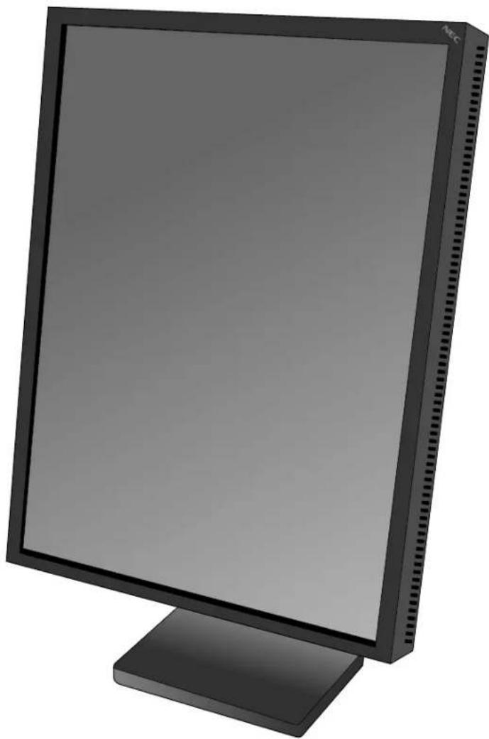
Front view of a black desktop computer monitor with a blank screen and stand (no visible text or symbols)INSTALLATION & MAINTENANCE GUIDE
INSTALLATIONS- UND WARTUNGSHANDBUCH
GUIDE D'INSTALLATION ET DE MAINTENANCE
取扱説明書
安装与维护指南
MD21GS-2MP

WARNING

TO PREVENT FIRE OR SHOCK HAZARDS, DO NOT EXPOSE THIS UNIT TO RAIN OR MOISTURE. ALSO, DO NOT USE THIS UNIT'S POLARIZED PLUG WITH AN EXTENSION CORD RECEPTACLE OR OTHER OUTLETS UNLESS THE PRONGS CAN BE FULLY INSERTED.
REFRAIN FROM OPENING THE CABINET AS THERE ARE HIGH VOLTAGE COMPONENTS INSIDE. REFER SERVICING TO QUALIFIED SERVICE PERSONNEL.

CAUTION:
CAUTION


TO REDUCE THE RISK OF ELECTRIC SHOCK, MAKE SURE POWER CORD IS UNPLUGGED FROM WALL SOCKET. TO FULLY DISENGAGE THE POWER TO THE UNIT, PLEASE DISCONNECT THE POWER CORD FROM THE AC OUTLET. DO NOT REMOVE COVER (OR BACK). NO USER SERVICEABLE PARTS INSIDE. REFER SERVICING TO QUALIFIED SERVICE PERSONNEL.
This symbol warns user that uninsulated voltage within the unit may have sufficient magnitude to cause electric shock. Therefore, it is dangerous to make any kind of contact with any part inside this unit.
This symbol alerts the user that important literature concerning the operation and maintenance of this unit has been included. Therefore, it should be read carefully in order to avoid any problems.
Power Cord Important Information
CAUTION: Please use the power cord provided with this display in accordance with the table below. If a power cord is not
supplied with this equipment, please contact your supplier. For all other cases, please use a power cord that matches the AC voltage of the power outlet and has been approved by and complies with the safety standard of your particular country.
When you use this Display in North America, you should use a North America Hospital Grade power cord.
| Plug Type European | North America Hospital Grade | Japanese (for Japanese Market only) | ||||
| Plug Shape | [gre and] |  | 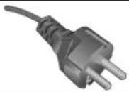 |  |  | |
| Country | U.S.A./ Canada EU (except U.K.) China | Japan | ||||
| Voltage | 120 230 220 | 100 | ||||
Intended Use
The MD21GS-2MP grayscale display is intended to be used for displaying and viewing of digital images for diagnosis by trained physicians. To guarantee the display performance as specified, it must only be used in conjunction with NEC recommended display cards.
European Customers

Unpacking, Installation and calibration of this display should only be done by authorized and trained personnel. Any installation done by a non-authorized person is done under his own risk and we accept no responsibility in any device malfunctioning.

Medical Imaging
The NEC MD21GS-2MP is designed for 2-megapixel (1200 x 1600) grayscale medical imaging. This display comes fully tuned with a setting for gamma correction that complies with the DICOM Part 14 Standard.
Canadian Department of Communications Compliance Statement
DOC: This Class B digital apparatus meets all requirements of the Canadian Interference-Causing Equipment Regulations. C-UL: Bears the C-UL Mark and is in compliance with Canadian Safety Regulations according to CAN/CSA C22.2 No. 601.1.
FCC Information
- Use the attached specified cables with the MD21GS-2MP grayscale display so as not to interfere with radio and television reception.
(A) Please use the supplied power cord or equivalent to ensure FCC compliance.
(B) Please use the supplied shielded video signal cable, DVI-D to DVI-D cable.
Use of other cables and adapters may cause interference with radio and television reception.
-
This equipment has been tested and found to comply with the limits for a Class B digital device, pursuant to part 15 of the FCC Rules. These limits are designed to provide reasonable protection against harmful interference in a residential installation. This equipment generates, uses, and can radiate radio frequency energy, and, if not installed and used in accordance with the instructions, may cause harmful interference to radio communications. However, there is no guarantee that interference will not occur in a particular installation. If this equipment does cause harmful interference to radio or television reception, which can be determined by turning the equipment off and on, the user is encouraged to try to correct the interference by one or more of the following measures:
-
Reorient or relocate the receiving antenna.
- Increase the separation between the equipment and receiver.
- Connect the equipment into an outlet on a circuit different from that to which the receiver is connected.
- Consult your dealer or an experienced radio/ TV technician for help.
If necessary, the user should contact the dealer or an experienced radio/ television technician for additional suggestions. The user may find the following booklet, prepared by the Federal Communications Commission, helpful: "How to Identify and Resolve Radio-TV Interference Problems." This booklet is available from the U.S. Government Printing Office, Washington, D.C., 20402, Stock No. 004-000-00345-4.
Your new NEC Display display box* should contain the following:
- MD21GS-2MP Display with tilt/ swivel/ pivot/ height adjustable stand
• Power Cords (N.A. Hospital Grade, European Continental and Chinese) ^2 - Quick Reference Guide
• Installation and Maintenance Guide
• Video Signal Cable (DVI-D to DVI-D cable)
• CD-ROM (GammaComp MD) - Ferrite Core x 2
- Sensor Hook

text_image
Power Cords *3 *3 Sensor Hook NEC MD21GS-2MP NEC INSTALLATION & INSTALLATION CODE INSTALLATION, PRO-ACTOR PROCESSED BY INSTALLATION OF INSTALLATION CODE 双面射频器 安装与维护装置 MD21GS-2MPQuick Reference Guide Installation & Maintenance Guide

natural_image
Illustration of a computer monitor with a video signal cable attached (no text or symbols on the device itself)
natural_image
Simple illustration of a CD-ROM disc with no text or symbols on the disc itself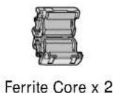
For complete display card instructions, please refer to the display card installation guide.
For GammaComp MD Quality Control Software, please refer to GammaComp MD User's Guide.
* Remember to save your original box and packing material to transport or ship the display.
^*2 For Japanese market model, only power cord for Japan is provided with this display.
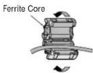
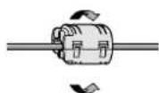
*3 For Power Cord (European continental and Chinese type)
1 Open the ferrite core and damp it on the power cord.
2 Close the ferrite core. Attach the Ferrite Core to the end of Power cord. Only AC-IN (connector) side of display.

Display Card\* Installation
- Following your PC manufacturer's guidelines, open your computer to access the PCI, AGP or PCI E slot.
- Place the display card into an available PCI, AGP or PCI E slot and secure all screws.
- Replace the computer cover.
NOTE: For information on installing drivers, display modes in multimonitor mode, the setting the dip switches, please refer to the display card manufacturer's documentation.
* A Display card is optional for the United States, it is included as a standard accessory for Europe.
Connecting the LCD to Your PC
Once the display card is successfully installed, follow these instructions to connect the display to your PC.
- Shut down your computer and turn off the power.
- For the PC with DVI digital output: Connect the DVI signal cable to the connector of the display card in your system (Figure A.1). Tighten all screws.
For the PC with Analog output: Connect the 15-pin mini D-SUB signal cable (not included) to the connector of the display card in your system (Figure A.2). Tighten all screws.
NOTE: For dual displays, plug a DVI-D cables into Port 1 and Port 2 of the display card (Figure A.1). For further information on display card installation, refer to the display card manual.
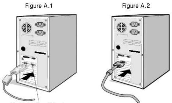
Port 2 for Dual Display
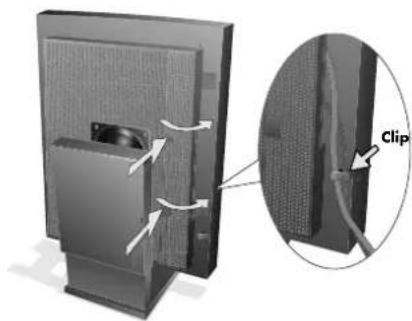
- Remove the cable cover by pressing the two tabs to unlock. Lift the cover to remove (Figure B.1).
Figure B.1
natural_image
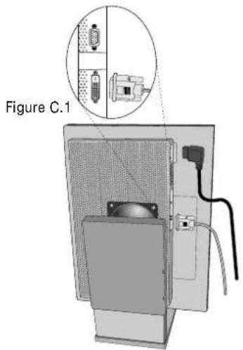
Diagram of a computer monitor with a clip and cable, showing internal components and directional arrows (no text or symbols)- For digital input: Connect the DVI-D signal cable to the connector on the back of the display (Figure C.1).
For analog input: Connect the 15-pin mini D-SUB signal cable (not included) to the connector on the back of the display (Figure C.2).
NOTE: Incorrect cable connections may result in irregular operation, damage display quality/ components of LCD module, and/ or shorten the module life.
- Connect one end of the power cord to the AC inlet on the back of the display and the other end to the power outlet (Figure C.1). Replace the cable cover.
NOTE: Refer to the Display Adjustment & Mounting section to check tilt, raise and lower display screen and screen rotation when you manage cables and power cord.
NOTE: Please refer to the Power Cord Important Information section of this manual for proper selection of AC power cord.
- Collect cables and power cord and place them under the cable clip (Figure B.1).
NOTE: Release the cables from the clip before removing the cable cover.
text_image
Figure C.1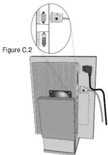
text_image
Figure C.2- Turn on the display with the power switch on the top (portrait) or left side (landscape) of the display (Figure D.1). Turn on the computer.
NOTE: DO NOT switch on/off repeatedly.
- For further adjustments, please refer to the OSM section for a full description of OSM controls.
NOTE: If you have any problems, refer to the Troubleshooting section.
NOTE: External equipment intended for connection to signal input, signal output, or other connectors, must comply with the relevant IEC standard.

natural_image
Computer monitor with a magnified inset showing a grid pattern, labeled 'Figure D.1' (no text or symbols on the main subject)The On-Screen Manager (OSM) control buttons are located on the back of the display. To access the OSM menu, press any of the user control buttons (<, >, -, +).

text_image
9 SENSOR 1 2 3 4 5 6 7 8 Portrait Mode 1. BVI: DIGITAL 1200X1800/ 60.0Hz Landscape Mode 10-
LED Indicates power on and signal condition. The LED can be turned on, off, or dimmed. Please refer to the Advanced OSM section/LED Brightness for further information. Green – signal is present and power is on Orange – no signal
-
RESET Resets the highlighted control menu to the factory setting.
-
SELECT Enters the OSM controls and OSM sub menu.
Changes signal input.
4/5. ADJUST -/+ Moves the bar left/right to increase or decrease the adjustment.
6/7. CONTROL </> Moves the highlighted area left/right to select control menus.
Moves the highlighted area up/ down to select one of the controls.
-
EXIT Exits the OSM Controls and OSM Main Menu.
-
Sensor Port For optional external sensor used for self calibration and copy calibration.
-
On-Screen The key guide will automatically appear on the screen when any control button on the
Key Guide back is pressed. The key guide will change orientation along with the OSM.
NOTE: When RESET is pressed in the main and sub-menu, a warning window will appear allowing you to cancel the RESET function by pressing the EXIT button.
Safety Precautions and Maintenance

FOR OPTIMUM PERFORMANCE, PLEASE NOTE THE FOLLOWING WHEN SETTING UP AND USING THE NEC DISPLAY:

- DO NOT OPEN THE Display. There are no user serviceable parts inside and opening or removing covers may expose you to dangerous shock hazards or other risks. Refer all servicing to qualified service personnel.
- Do not spill any liquids into the cabinet or use your display near water.
- Do not insert objects of any kind into the cabinet slots, as they may touch dangerous voltage points, which can be harmful or fatal or may cause electric shock, fire or equipment failure.
- Do not place any heavy objects on the power cord. Damage to the cord may cause shock or fire.
- Do not place this product on an unbalanced or unstable cart, stand or table because the display may fall, causing serious damage.
- Do not place any objects onto the display and do not use the display outdoors.
- The inside of the fluorescent tube located within the display contains mercury. Please follow the bylaws or rules of your municipality to dispose of the tube properly.
- Do not bend power cord.
- Do not use display in high tempered, humid, dusty, or oily areas.
- Do not cover vent on display.
Immediately unplug your display from the wall outlet and refer servicing to qualified service personnel under the following conditions:
- When the power supply cord or plug is damaged.
- If liquid has been spilled, or objects have fallen into the display.
- If the display has been exposed to rain or water.
- If the display has been dropped or the cabinet damaged.
- If the display does not operate normally by following operating instructions.
- If glass is broken, handle with care.
- If display or glass is broken, do not come in contact with the liquid crystal and handle with care.

- Allow adequate ventilation around the display so that heat can properly dissipate. Do not block ventilated openings or place the display near a radiator or other heat sources. Do not put anything on top of display.
- The power cable connector is the primary means of detaching the system from the power supply. The display should be installed close to a power outlet which is easily accessible.
- Handle with care when transporting. Save packaging for transporting.
Image Persistence
Please be aware that LCD Technology may experience a phenomenon known as Image Persistence. Image Persistence occurs when a residual or "ghost" image of a previous image remains visible on the screen. Unlike CRT monitors, LCD monitors' image persistence is not permanent, but constant images being displayed for a long period of time should be avoided. To alleviate image persistence, turn off the monitor for as long as the previous image was displayed. For example, if an image was on the monitor for one hour and a residual image remains, the monitor should be turned off for one hour to erase the image.
NOTE: As with all personal display devices, NEC-Mitsubishi Electronics Display recommends displaying moving images and using a moving screen saver at regular intervals whenever the screen is idle or turning off the monitor when not in use.

CORRECT PLACEMENT AND ADJUSTMENT OF THE DISPLAY CAN REDUCE EYE, SHOULDER AND NECK FATIGUE. CHECK THE FOLLOWING WHEN YOU POSITION THE DISPLAY:

- For optimum results during self and copy calibrations, allow 30 minutes for warm-up.
- Adjust the display height so that the top of the screen is at or slightly below eye level. Your eyes should look slightly downward when viewing the middle of the screen.
- Position your display no closer than 16 inches and no further away than 28 inches from your eyes. The optimal distance is 20 inches.
- Rest your eyes periodically by focusing on an object at least 20 feet away. Blink often.
- Position the display at a 90^ angle to windows and other light sources to minimize glare and reflections. Adjust the display tilt so that ceiling lights do not reflect on your screen.
- Clean the display surface with a lint-free, non-abrasive cloth. Case of persistent dirt, wipe with cloth permeated by water, ethanol, isopropyl-alcohol completely. Avoid using any cleaning solution or glass cleaner (ex Acid, Alkali and Acetone).
- Adjust the display's brightness control to enhance readability.
- Position whatever you are looking at most of the time (the screen or reference material) directly in front of you to minimize turning your head while you are typing.
- Avoid displaying fixed patterns on the display for long periods of time to avoid image persistence (after-image effects).
Ergonomics
To obtain the best possible ergonomics benefits, we recommend the following:
- Use the preset Size and Position controls with standard signals
- Use non-interlaced signals with a vertical refresh rate of 60Hz
Cleaning the LCD Panel
- When the liquid crystal panel is stained with dust or dirt, please wipe with soft cloth gently.
- Please do not rub the LCD panel with hard material.
- Please do not apply pressure to the LCD surface.
- Please do not use OA cleaner it will cause deterioration or discolor on the LCD surface.
Cleaning the Cabinet
- Unplug the power supply
• Gently wipe the cabinet with a soft cloth
• To clean the cabinet, dampen the cloth with a neutral detergent and water, wipe the cabinet and follow with a dry cloth.
NOTE: Many plastics are used on the surface of the cabinet. DO NOT clean with benzene, thinner, alkaline detergent, alcoholic system detergent, glass cleaner, wax, polish cleaner, soap powder, or insecticide. Do not touch rubber or vinyl to the cabinet for a long time. These types of fluids and fabrics can cause the paint to deteriorate, crack or peel.

natural_image
Silhouette of a person sitting at a desk using a computer, no text or symbols visibleDisplay Specifications MD21GS-2MP Display Notes
| LCD Module Diagonal: 54 cm/21.3 inches Active matrix; thin film transistor (TFT) liquidViewable Image Size: 54 cm/21.3 inches crystal display (LCD); 0.270mm dot pitch;Native Resolution (Pixel Count): 1200 x 1600 (Portrait) 400 cd/m ^2 calibrated white luminance;1600 x 1200 (Landscape) 700:1 contrast ratio, typical. | ||
| Input Signal Video: Digital Input: DVI VideoDot Clock 162MHz MaxAnalog Input: ANALOG 0.7 Vp-p/75 OhmsSync: Separate sync.TTL LevelHorizontal sync. Positive/NegativeVertical sync. Positive/NegativeComposite sync. Positive/Negative | ||
| Grayscale Tones 10 Bit: 1024 (10bit) shades of gray fromWhen used with an NEC recommended 10 bita pallet of 3061 (11.5bit) display card8 Bit: 256 (8bit) shades of gray from a When used with an NEC recommended 8 bitpallet of 3061 (11.5 bit) display card | ||
| Synchronization Range Horizontal: 31.5 kHz to 91.1 kHz AutomaticallyVertical: 50 Hz to 85 Hz Automatically | ||
| Viewing Angle Left/Right: ±88° (CR > 10)Up/Down: ±88° (CR > 10) | ||
| Image Formation Time 35 ms (Typ.) | ||
| Active Display Area Portrait: Horiz.: 324 mm/12.8 inchesVert.: 432 mm/17.1 inchesLandscape: Horiz.: 432 mm/17.1 inchesVert.: 324 mm/12.8 inches | ||
| Power Supply AC 100-240V ~ 50/60Hz | ||
| Current Rating 0.7 - 0.35 A | ||
| Dimensions Portrait: 358.7 mm (W) x 514 - 560 mm (H) x 200 mm (D)14.1 inches (W) x 20.2 - 22.0 inches (H) x 7.9 inches (D)Landscape: 467 mm (W) x 460 - 506 mm (H) x 200 mm (D)18.4 inches (W) x 18.1 - 19.9 inches (H) x 7.9 inches (D)Height Adjustment: 46 mm/1.8 inches (Landscape) | ||
| Weight 11.7 kg/25.8 lbs | ||
| Environmental ConsiderationsOperating Temperature: 5°C to 40°C/41°F to 104°FHumidity: 30% to 80% (without condensation)Feet: 0 to 10,000 Feet/0 to 3,048 mStorage Temperature (in package): -20°C to 60°C/-4°F to 140°FHumidity (in package): 10% to 85% (without condensation)Feet (in package): 0 to 40,000 Feet/0 to 12,192 m |
UL-Classification
According to the type of protection against electric shock: CLASS I
According to the degree of protection against electric shock: No Patient connection
According to the degree of protection against ingress of water as detailed in the current edition of IEC529: No Protection
According to the method of sterilization or disinfection recommended by the manufacturer: Not Specified
According to the degree of safety of application in the presence of a FLAMMABLE AN AESTHETIC MIXTURE WITH AIR or a WITH OXYGEN OR NITROUS OXIDE: Not suitable
According to the mode of operation: Continuous operation
North America and Canada
NEC-Mitsubishi Monitor Customer Service & Support
Customer Service and Technical Support:
(800) 632-4662
Fax: (800) 695-3044
Parts and Accessories/ Macintosh
Cable Adapter: (888) NEC-MITS [888-632-6487]
Warranty Information: www.necmitsubishi.com/ warranty
Online Technical Support www.necmitsubishi.com/ support
Sales and Product Information
Sales Information Line: (888) NEC-MITS [888-632-6487]
Canadian Customers: (866) 771-0266, Ext#: 4037
Government Sales: (800) 284-6320
Government Sales email: gov@necmitsubishi.com
Electronic Channels
World Wide Web: www.necmitsubishi.com
Product Registration:
www.necmitsubishi.com/productregistration
Drivers and Downloads www.necmitsubishi.com/downloads
Europe
Address
NEC-Mitsubishi Electronics Display-Europe GmbH Phone: +49(0)89 99699 - 0
Landshuter Allee 12 -14
D-80637 München
Electronic Channels
World Wide Web: www.medical.nec-mitsubishi.com
This device complies with Part 15 of FCC Rules. Operation is subject to the following two conditions. (1) This device may not cause harmful interference, and (2) this device must accept any interference received, including interference that may cause undesired operation.
U.S. Responsible Party: NEC-Mitsubishi Electronics Display of America, Inc.
Address: 500 Park Blvd, Suite 1100
Itasca, Illinois 60143
Tel. No.: (630) 467-3000
Type of Product: Display Monitor
Equipment Classification: Class B Peripheral
Model:
MD21GS-2MP-CB/ MD21GS-2MP-BB

We hereby declare that the equipment specified above conforms to the technical standards as specified in the FCC Rules.
OSM and FullScan are registered trademarks of NEC-Mitsubishi Electronics Display of America in U.S. X-Light is a trademark of NEC-Mitsubishi Electronics Display of America in U.S. ErgoDesign is a registered trademark of NEC-Mitsubishi Electric Visual Systems Corporation in Austria, Netherlands, Denmark, France, Germany, Italy, Republic of Indonesia, Republic of Korea, Kingdom of Thailand, Malaysia, Norway, Spain, Taiwan, U.K., U.S., Canada. Microsoft and Windows are registered trademarks of Microsoft Corporation in the United States and other countries. All other brands and product names are trademarks or registered trademarks of their respective owners.
Declaration of the Manufacturer
We hereby certify that the grayscale monitor MD21GS-2MP-CB/ MD21GS-2MP-BB are in compliance with Council Directive 93/ 42/ EEC:
- EN 60601-1
- EN 60601-1-2
- EN 61000-3-2
- EN 61000-3-3
and marked with CE.
NEC-Mitsubishi Electronics Display-Europe GmbH
Landshuter Allee 12-14, D-80637 Munich