
WH-EXT500 - Hi-Fi System Anchor Audio - Free user manual and instructions
Find the device manual for free WH-EXT500 Anchor Audio in PDF.

| Product Type | Wireless Microphone System (UHF) |
| Model | WH-EXT500 / UHF-EXT500 |
| Frequency Range | UHF 540–570 MHz (Regionally Selected) |
| Number of Channels | 700 Selectable |
| Modulation | FM |
| Oscillator | PLL Synthesized |
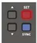
| Receiver Audio Output | Balanced XLR and Unbalanced 1/4" |
| Receiver Dimensions (H x W x D) | 1.65" x 7.9" x 7.2" (4.2 x 20 x 18.3 cm) |
| Receiver Weight | 2.05 lbs (0.93 kg) |
| Handheld Microphone Dimensions (H x Dia) | 10.2" x 2.1" (26 x 5.4 cm) |
| Handheld Microphone Weight | 0.52 lbs (0.234 kg) |
| Belt Pack Dimensions (H x W x D) | 3.8" x 2.5" x 0.95" (9.7 x 6.5 x 2.4 cm) |
| Belt Pack Weight | 0.19 lbs (0.086 kg) |
| Receiver Power Supply | DC 12V (included adapter) |
| Transmitter Battery | 2x AA (alkaline or rechargeable) |
| RF Power Output | 10 mW (max) |
| Audio Output Level Adjustment | Mic (-20 dB) / Line (0 dB) switch on receiver |
| Squelch Control | Adjustable rotary knob on rear panel |
| Synchronization | One-touch SYNC button (transmitter & receiver) |
| Channel Setting Modes | Manual, Auto-Scan, Preset (4 groups of 8 channels) |
| Mounting | Half 19" EIA rack mount (included hardware) |
| Included Items | Receiver, handheld mic or belt pack, power adapter, rack mount kit, AA batteries |
| Warranty | 6 years (receiver), 2 years (microphones/transmitters) |
Frequently Asked Questions - WH-EXT500 Anchor Audio
User questions about WH-EXT500 Anchor Audio
0 question about this device. Answer the ones you know or ask your own.
Ask a new question about this device
Download the instructions for your Hi-Fi System in PDF format for free! Find your manual WH-EXT500 - Anchor Audio and take your electronic device back in hand. On this page are published all the documents necessary for the use of your device. WH-EXT500 by Anchor Audio.
USER MANUAL WH-EXT500 Anchor Audio
natural_image
Exterior view of a WR-EXT500 audio recording device with microphone and two speakers (no visible text or symbols on main body)MESSAGE FROM ANCHOR AUDIO
Congratulations on purchasing an Anchor Audio wireless system! You have joined the thousands of satisfied customers including the various professional athletic teams, prestigious universities, school districts nationwide, first responders, and the branches of the U.S. Military.
From developing our products on giant sticky notes to testing them in the parking lot and driving our neighbors crazy, our hearts - and ears - are 110% committed to delivering reliable battery powered portable sound systems and portable PA systems for you. But we don't stop there. Anchor Audio is proudly manufactured in America and has plenty more solutions for you to choose from: speaker monitors, conference systems, assistive listening, lecterns, and intercoms. We are your best friend in portable sound and are here for you when you need us...or even when you don't. We're just a phone call away. With over 40 years of experience, our Engineering and Production to Sales and Tech Support teams will provide you with the most reliable portable audio products and customer service.
Welcome to the Anchor Audio family! Feel free to contact us at any time. We'd love to hear from you.

Alex Jacobs
President
CONTENTS
QUICK START GUIDE 3
CONNECTING THE RECEIVER....7
SETTING UP CHANNEL ON RECEIVER....8
SETTING UP THE HANDHELD MICROPHONE / BELT PACK TRANSMITTER....11
SYNCHRONIZING A TRANSMITTER WITH A RECEIVER 12
COLOR AND LABEL IDENTIFICATION 13
BASIC CONNECTIONS 14
TROUBLESHOOTING....14
TECHNICAL SPECIFICATIONS....15
IMPORTANT SAFETY INSTRUCTIONS....16
ANCHOR AUDIO WARRANTY / ANCHOR AUDIO RETURN AUTHORIZATION PROCEDURES....18
GETTING STARTED
Please check your new unit carefully for any damage which may have occurred during shipment. Each Anchor Audio product is carefully inspected at the factory and packed in specially designed boxes for safe transport.
Notify the freight carrier immediately of any damage to the shipping box or product. Repack the unit in the original box and wait for inspection by the carrier's claim agent. Notify your Anchor Audio authorized dealer of the pending freight claim.
NOTE: All damage claims must be made with freight carrier!
RETURNING SYSTEMS FOR SERVICE OR REPAIR
For service or repair, please call us at 1-800-262-4671 x782 or visit www.anchoraudio.com/technical-support-form.html
Our Technical Support team will help to troubleshoot. If unsuccessful and under warranty, they will issue you a Return Merchandise Authorization (RMA) number. Once you ship your product back to Anchor Audio with the RMA number clearly noted on the box, we will diagnose your unit and repair your unit then ship it back to you. All products must be shipped prepaid. C.O.D. shipments and shipments without an RA number will be refused and returned at your expense. See page 18 for additional information.
UHF-EXT500
INTRODUCTION
The PLL synthesized wireless microphone system operates in UHF 540 - 570 MHz frequency band with 700 selectable channels. Please read this instruction manual carefully before operating the system. This manual covers the function and operation of the wireless microphone system.
FCC STATEMENT
This device complies with part 15 of the FCC rules. Operation is subject to the following two conditions. (1) This device may not cause harmful interference, and (2) this device must accept any interference received, including interference that may cause undesired operation.
Notice: The changes or modifications not expressly approved by the party responsible for compliance could void the user's authority to operate the equipment.
IMPORTANT NOTE: To comply with the FCC RF exposure compliance requirements, no change to the antenna or the device is permitted. Any change to the antenna or the device could result in the device exceeding the RF exposure requirements and void user's authority to operate the device.
SAFETY
- Do not spill liquid on the appliance, and do not drop it on a hard concrete floor.
- Do not place the equipment near heat sources such as radiators, heating ducts, amplifier, etc.
- Do not expose the equipment to direct sunlight, extreme dust, shock, or excessive moisture, rain, mechanical vibrations.
- If the unit has been not used for a long period of time, remove the battery from the transmitter as this will avoid potential damage resulting from a defective leaking battery.
- If the equipment is not going to be used for a long period of time, disconnect the AC adapter from the power outlet. Please note that if you turn the equipment off while leaving the AC adapter plugged in, it is not fully isolated from the power supply.
- WARNING: To reduce the risk of fire or electric shock, do not use the products near water and do not expose them to rain or moisture.
ENVIRONMENT
- Do not throw used batteries into fire or garbage. Be sure to dispose of use batteries in accordance with local waste disposal rules and regulations.
- When disposing of the equipment, remove the batteries, separate the case, circuit boards, and cables and dispose of all components in accordance with local waste disposal rules.
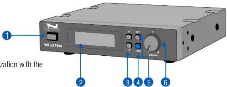
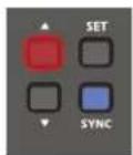
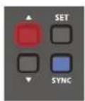
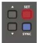
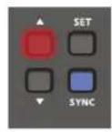
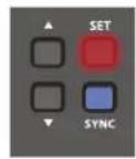
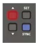
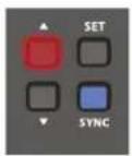
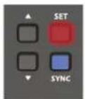
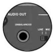
- Power Button
- LCD Display: Display channel, frequency and settings
- Button ▲▼: Tap the channel forward/backward
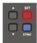
- SYNC Button: Press the button to actuate the synchronization with the transmitter
- SET Button: Press button to activate the manual or auto-scan or preset mode
- Volume Controller: Adjust the receiver output level
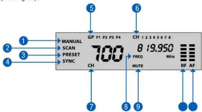
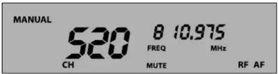
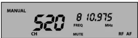
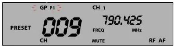
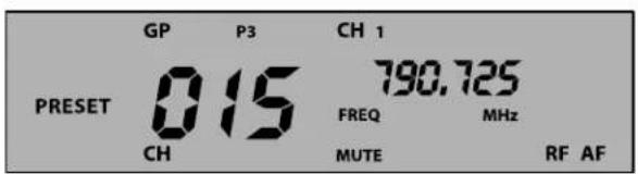
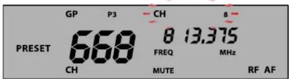
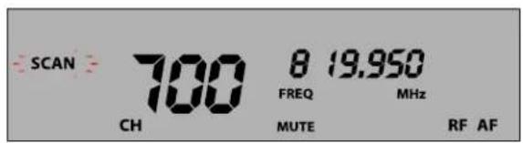
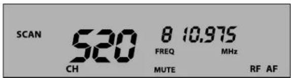
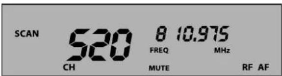
LCD Display
- MANUAL: Use this mode to select free channel manually
- SCAN: Use this mode to set free channel by auto-scan function
- PRESET: Use this mode to set multiple constructions by preset group
- SYNC: The synchronization process is actuated
- GP: Display selected preset group
- CH: Display selected preset channel
- CH: Display selected channel number
- FREQ: Display selected frequency
- MUTE: Audio output is muted
- RF Bar: Display the reception status of RF signal
- AF Bar: Display the reception status of AF signal
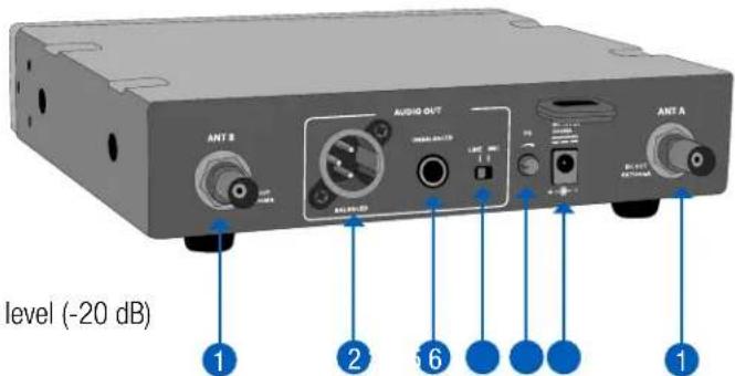
Rear Back Panel
- Antenna
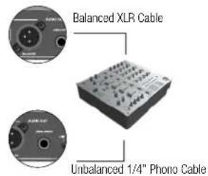
- Balanced XLR Audio Output
- Unbalanced 1/4" Audio Output
- Mic/Line Switch: Use this to adjust audio output level for mic level (-20 dB) or line level (0 dB)
- Squelch: turn the knob to adjust or decrease the noise floor level
- Power Adapter Connector
- Power Button: Press for 2 seconds to power the microphone on or off
- Power LED: Indicates the power/low battery level status.
| LED Indicator Status | |
| Green Ready | |
| Flashing Green The synchronization process is actuated | |
| Flashing Red Low battery power with less than 10 minutes of operation left | |
- Talk Button: Push the button up to talk.
- SYNC Button: Press to actuate the synchronization process with the receiver
- LCD Display: Display channel number and battery power level.
- Battery Compartment: Insert two AA dry or rechargeable batteries into the compartment and make sure that the polarity of the batteries is correct.
- Grille: Protects the microphone capsule and helps reduce breath sounds and wind noise.
- Power Button: Press for 2 seconds to power the belt pack on or off.
- Mute Button: With the transmitter on, a slight press of button will toggle between mute and unmute function.
- Power LED: Indicates the power/low battery level status.
| LED Indicator Status | |
| Green Ready | |
| Flashing Green The synchronization process is actuated | |
| Flashing Red Low battery power with less than 10 minutes of operation left | |
- MUTE LED: Blue LED light on means unit is in mute status.
- SYNC Button: Press to actuate the synchronization process with the receiver.
- LCD Display: Display channel number and battery power level.
- Battery Compartment: Insert two AA dry or rechargeable batteries into the compartment and make sure that the polarity of batteries is correct.
- Mini XLR Connector: Connect to the lapel microphone or headset microphone.
- Gain Switch: The switch sets the audio input to -20dB, -10dB, or 0dB.
SETTING UP THE HANDHELD MICROPHONE / BELT PACK TRANSMITTER
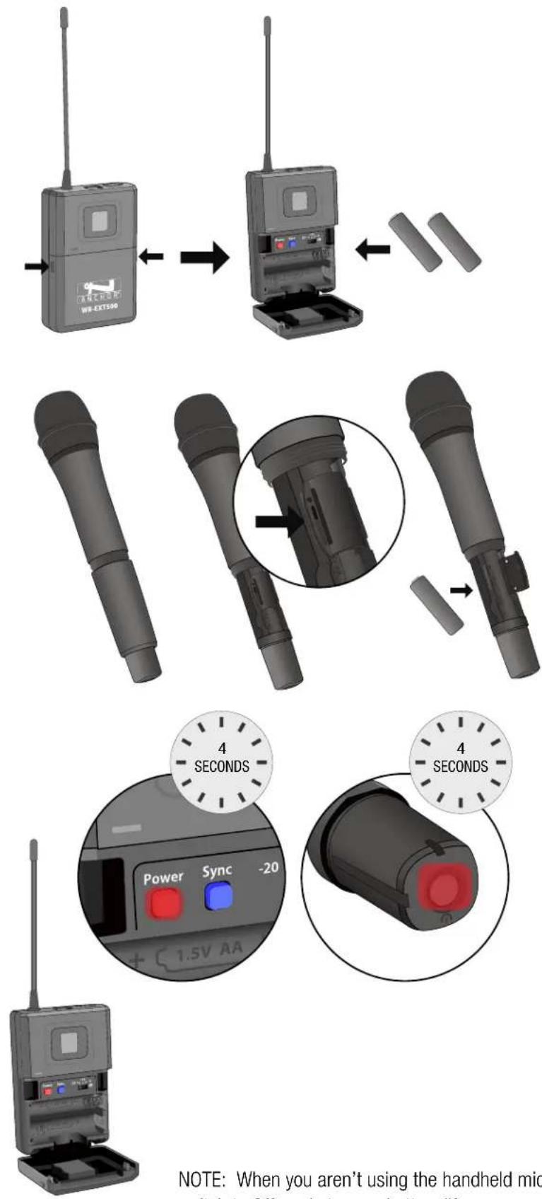
Open the battery cover and insert batteries into the battery compartment conforming to the polarity +/- marks.
Unscrew the handheld Mic and open the battery cover to insert the battery into the battery compartment and confirm the marks of the polarity +/- .
Press for 4 seconds to turn the Handheld/Belt pack transmitter on.
If the LED stays flashing. It indicates that the battery will be out of power soon and should be replaced.
Adjust the audio input level.
-0dB (default setting)
-10dB
-20dB
NOTE: When you aren't using the handheld mic/belt pack for a long period of time, move the power switch to Off mode to save battery life.
SETTING UP CHANNEL ON RECEIVER
Notice: Do not put two or more transmitters operating nearby when setting up the frequency channel. Please keep transmitter at least one meter away from receiver.
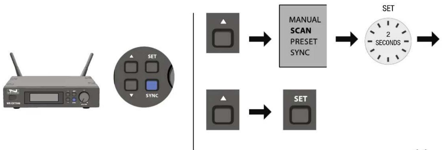
Manual Mode
Setting up interference-free channel by manual operation

Using the ▲ button to select the "MANUAL" mode.


Press "SET" button for 2 seconds till LCD display is flashing.
Press ▲ button to change the channel forward.
Press "SET" button to lock the setting.
Preset Mode
Set multiple channels by using preset channels. There are 4 preset groups. Excluding the interference from external, there are 8 preprogrammed channels that can be operated simultaneously in each group.

Use the ▲ button to select the "PRESET" mode.

Press "SET" button for 2 seconds till LCD display is flashing.

Press the channel button ▲ to change the programmable group forward.

Press "SET" button to lock group setting.
Press the channel button ▲ to change the programmable channel forward.

Press "SET" button to lock the channel setting.
NOTE: When there is any interference on the current preset group, switch to the next preset group. If all 4 preset groups have interference, use the auto-scan mode or manual mode to set up the system.
Auto-Scan Mode
Set interference-free channel by automatic frequency function.
Using the ▲ button to select the "SCAN" mode.

Press "SET" button for 2 seconds till LCD display is flashing.

Press button ▲ to scan in forward direction, and it will stop at the free-interference channel automatically.
Press the "SET" button to lock the setting.
Insert Batteries


SYSTEM OPERATION
Prior to setting up, please check that the transmitter and receiver are tuned to the same frequency or channel. Two or more transmitters operating in the same frequency can not be used at the same time and same area.

natural_image
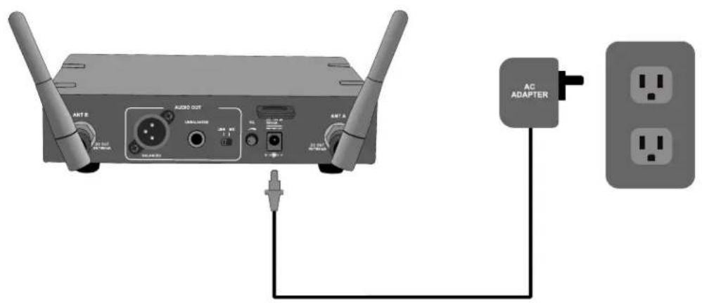
Diagram showing a wireless router connected to a power outlet (no text or symbols present)Connect the provided DC power supply to the receiver with an appropriate AC power source. The receiver is on when the LCD screen display lights up.
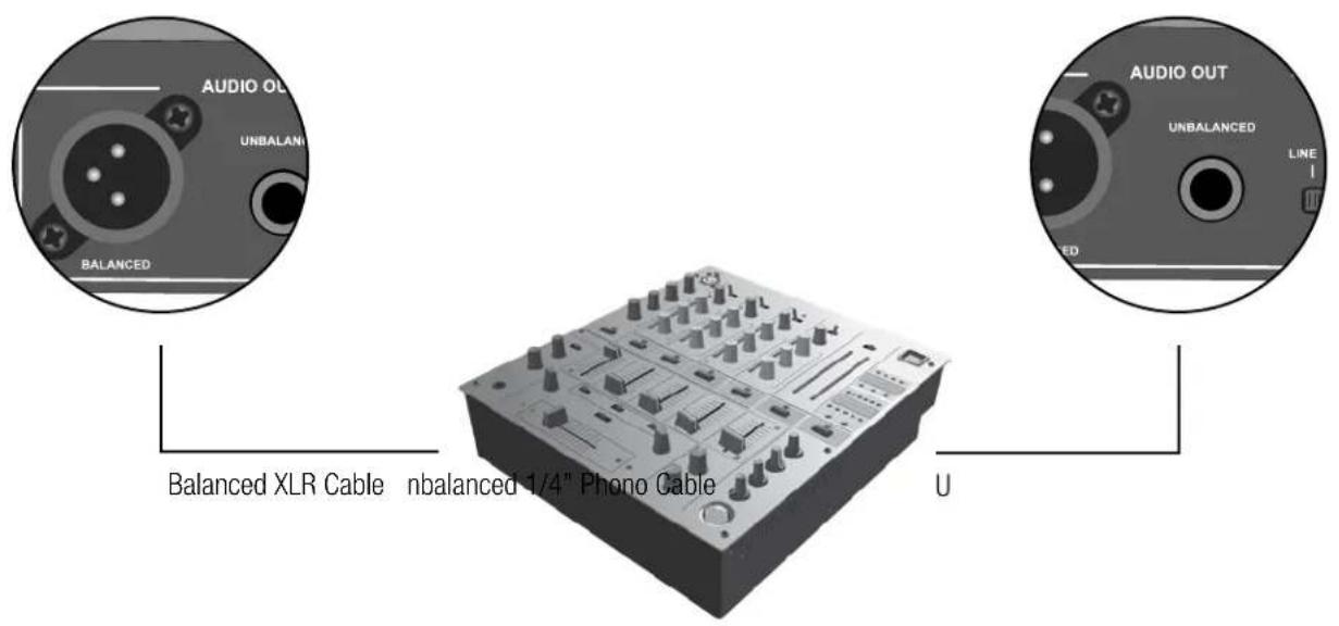
Using a standard audio cable with 3-pin XLR connectors or 1/4" phono cable to connect the mixer or amplifier
Never use the balanced and unbalanced audio outputs at the same time. This may cause signal loss or increased noise
Set the audio output level for
MIC: -20dB
LINE: 0dB (Default setting)
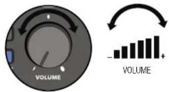
Using the Volume Knob to adjust the AF audio level to the input of the amplifier or mixer.
Default settings: In minimum VOLUME position.

Use the SQ (squelch) to avoid reproducing noise when the receiver does not receive enough signal from the transmitter.
Turn clockwise to increase squelch and reduce noise. When turning the squelch knob clockwise, it begins to eliminate background noise.
When squelch is all the way to the left, the squelch is off and the ambient RF noise will be easily heard.
Default settings: In minimum SQ position.
QUICK START GUIDE
- Connect Receiver to Power Cable then plug into a Grounded Power Outlet
- Connect Mixer or Amplifier
- Scan Free Channel
flowchart
graph LR
    A["Wire EXT500"] --> B["SET SYNC"]
    B --> C["MANUAL SCAN PRESET SYNC"]
    C --> D["2 SECONDS"]
    D --> E["SET"]
SYNCHRONIZING A TRANSMITTER WITH A RECEIVER
Automatic frequency synchronization via remote channel for easy setup
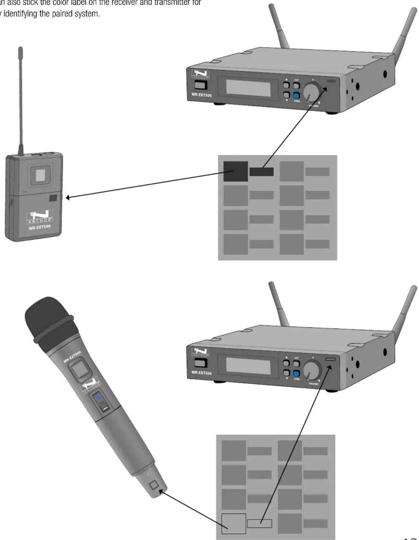
- First, switch the transmitter and the receiver on. Press and hold the SYNC button on your transmitter. The SYNC flashes on the receiver display panel.
Press the SYNC button on the receiver front panel, the transmitter will set the same channel as receiver automatically. - When using SYNC setting, the distance of receiver and transmitter should be within 1 meter.


PRESS AND HOLD SYNC
natural_image
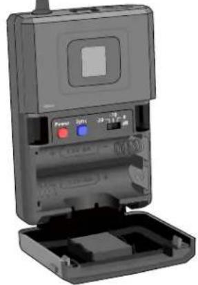
3D rendering of a device with open base, power button, and control panel (no visible text or symbols)Step 1
USE BELT PACK OR HANDHELD MICROPHONE
PRESS AND HOLD SYNC

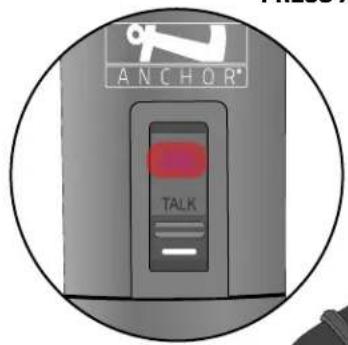
COLOR AND LABEL IDENTIFICATION
You can also stick the color label on the receiver and transmitter for quickly identifying the paired system.
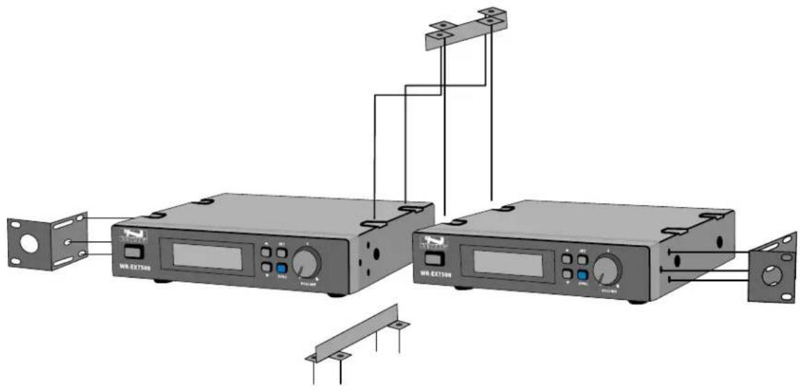
MOUNTING THE RECEIVER
To combine two receivers in 19" standard rack, use the two short L type metal racks and two metal connecting plates, included in the UHF-EXT500 box.
natural_image
Diagram of two wireless equipment units connected via a cable, showing front panel, control panel, and connector (no text or symbols present)TROUBLESHOOTING
| UHF-EXT500 | |
| Problem | Solution |
| No Sound | Check the power supply of the microphone and receiverCheck that the transmitter and receiver are tuned to the same frequencyCheck whether the hI-fi appliance is switched on and the receiver output is connected to audio mixer or amplifier inputCheck whether transmitter is too far away from receiver or SQUELCH control set too highCheck whether receiver is located too near metal object or there are obstructions between transmitter and receiver |
| Sound Interference | Check the antenna locationWhen using 2 or above microphone sets simultaneously, make sure that the chosen frequencies are not interferedCheck whether the interference comes from other wireless microphones, TV, radio and etc. |
| Distortion | Check the receiver volume level whether is set too high or too lowCheck whether the interference comes from other wireless microphones, TV, radio and etc. |
TECHNICAL SPECIFICATIONS
| UHF-EXT500 | |
| Receiver | |
| Frequency Range | UHF 540 ~ 570 MHz (Regionally Selected) |
| Case | Half 19" EIA Rack Metal Case |
| Oscillator | PLL Synthesized |
| Modulation | FM |
| S/N Radio | >100 dB at 200 KHz deviation and 60 dBμV antenna input |
| Image & Spurious Rejection | 70 dB minimum |
| Receiving Sensitivity | At 2μV over 52 dB S/N ratio |
| AF Response | 80 Hz to 18 KHz |
| T.H.D. | <1% (at 1 KHz) |
| IF Frequency | st: 243.95 MHz 2nd: 10.7 MHz |
| Dynamic Range | >100 dB |
| Tone Signal | 32.768 KHz |
| Audio Output | Balanced & Unbalanced |
| Power Supply | DC 12V |
| Current Consumption | 260 ± 10 mA |
| Dimensions and Weight | |
| Total (HWD) | 1.65" x 7.9" x 7.2" (4.2 x 20 x 18.3 cm) |
| Weight | 2.05 lbs / 0.93 Kg |
| Handheld / Belt Pack Transmitter | |
| Frequency Range | UHF 540 ~ 570 MHz (Regionally Selected) |
| Channel Select | SYNC with Receiver |
| Display | LCD displays status, channel, or battery |
| RF Power Output | 10 mW (max.) |
| Frequency Stability | ± 0.005% |
| Spurious Emission | >60 dB below carrier frequency |
| Gain Setting | Belt Pack: 0 dB, -10 dB, -20 dB (3 settings) |
| Mic Unit | Handheld: Uni-Direction dynamic unit or Uni-Direction electret condenser unit |
| Belt Pack: Lavalier Mic / Headset Mic | |
| Battery | 1. DC2.4V (1.2V x 2 AA size rechargeable batteries)2. DC3V (1.5V x 2 AA size batteries) |
| Current Consumption | 120 ± 10 mA |
| Dimensions and Weight | |
| Total (HW) | Handheld: 10.2" x 2.1" (26 x 5.4 cm) |
| Total (HWD) | Belt Pack: 3.8" x 2.5" x .95" (9.7 x 6.5 x 2.4 cm) |
| Weight | Handheld: 0.52 lbs /0.234 Kg |
| Weight | Belt Pack: 0.19 lbs /0.086 Kg |
IMPORTANT SAFETY INSTRUCTIONS

General Warning or Caution
The Exclamation Symbol in the figure to the left appears in Warning and Caution tables throughout this document. This symbol designates an area where personal injury or damage to the equipment is possible.

Electric Shock
The Electrical Shock Symbol in the figure to the left appears throughout this manual. This symbol indicates a hazard arising from dangerous voltage. Any mishandling could result in irreparable damage to the equipment and personal injury or death.

Protective Conductor Terminal
The Electrical Shock Symbol in the figure to the left appears throughout this manual. This symbol indicates a hazard arising from dangerous voltage. Any mishandling could result in irreparable damage to the equipment and personal injury or death.

European Union CE Mark
The presence of the CE Mark on Anchor Audio equipment means that it has been designed, tested, and certified as complying with all applicable European Union (CE) regulations and recommendations.

Alternating Voltage Symbol
The alternating voltage symbol means that the unit can also be used with AC (alternating current) that is in the form of electric power from a wall socket.
Figure DC Voltage Symbol
Direct Current Symbol
This international symbol implies a direct voltage or current.

Fuses
The fuse symbol in the figure to the left identifies the fuse location on the Anchor Audio product. (Not required if not user replaceable)

On Symbol
The On Symbol in the figure to the left represents a power switch position on the Anchor Audio product. This symbol represents a Power On condition.

Off Symbol
The Off Symbol in the figure to the left represents a power switch position on the Anchor Audio product. This symbol represents a Power Off condition.
Waste Electrical and Electronic Equipment (WEEE)
This symbol on the product or on its packaging indicates that this product must not be disposed of with regular waste. Instead, it is the user's responsibility to dispose of waste equipment according to the local laws. The separate collection and recycling of the waste equipment at the time of disposal will help to conserve natural resources and ensure that it is recycled in a manner that protects human health and the environment. For information about where the user can drop off the waste equipment for recycling, please contact your local authority for recycling advice.
Inspection for Damage
Anchor Audio products are carefully packaged at the factory to minimize the possibility of damage during shipping. Inspect the box for external signs of damage or mishandling. Inspect the contents for damage. If there is visible damage to the instrument upon receipt, inform the shipping company and Anchor Audio immediately.

Inspection for Damage
Do not attempt to operate this equipment if there is evidence of shipping damage or you suspect the unit is damaged. Damaged equipment may present additional hazards to you. Contact Anchor Audio Technical Support for advice before attempting to plug in and operate damaged equipment.
Anchor Audio Technical Support: 800.262.4671 x782
Electrical Requirements
Before attempting to power up the unit for the first time, the following precautions must be followed:

WARNING
To avoid electric shock, connect the instrument to properly earth-grounded, 3-prong receptacles only. Failure to observe this precaution can result in severe injury.
Have a qualified electrician verify the wall socket that will be used is properly polarized and properly grounded.
Warning: To reduce the risk of fire or electric shock, do not expose this apparatus to rain or moisture, apparatus shall not be exposed to dripping or splashing and no objects filled with liquids, such as vases or cups, shall be placed on the apparatus.
The apparatus should be connected to a main socket outlet with a protective earthing connection. For Nordic markings refer to copy of marking label. The plug in the power cord is the AC mains disconnected device and must remain readily operable.
There should be a minimum distance around the apparatus for sufficient ventilation. The ventilation should not be impeded by covering the ventilation openings with items, such as newspapers, table-cloths, curtains, etc.; no naked flame sources, such as lighted candles, should be placed on the apparatus.
Equipment may be located above or below this apparatus, but some equipment (like large amplifiers) may cause an unacceptable amount of hum or may generate too much heat and degrade the performance of this apparatus.

WARNING: Cancer and Reproductive Harm - www.P65Warnings.ca.gov.
IMPORTANT SAFETY INSTRUCTIONS (CONT'D)
1) Read Instructions – All the safety and operation instructions should be read before the product is operated.
2) Retain Instructions – The safety and operating instructions should be retained for future reference.
3) Heed Warnings – All warnings on the product and in the operating instructions should be adhered to.
4) Follow Instructions – All operating and use instructions should be followed.
5) Cleaning – Unplug this product from the wall outlet before cleaning. Do not use liquid cleaners or aerosol cleaners. Use a damp cloth for cleaning.
Exception: A product that is meant for uninterrupted service and that for some specific reason, such as the possibility of the loss of an authorization code for the CATV converter, is not intended to be unplugged by the user for cleaning or any other purpose, may exclude the reference to unplugging the product in the cleaning description otherwise).
6) Attachments – Do not use attachments not recommended by the product manufacturer as they may cause hazards.
7) Water and Moisture – Do not use this product near water – for example, near a bath tub, wash bowl, kitchen sink, or laundry tub; in a wet basement; or near a swimming pool; and the like.
8) Accessories – Do not place this product on an unstable cart, stand, tripod, bracket, or table. The product may fall, causing serious injury to a child or adult and serious damage to the product. Use only with a cart, stand, tripod, bracket, or table recommended by the manufacturer or sold with the product. Any mounting of the product should follow the manufacturer's instructions and should use a mounting accessory recommended by the manufacturer.
9) A product and cart combination should be moved with care. Quick stop, excessive force, and uneven surfaces may cause the product and stand combination to overturn.
10) Ventilation – Slots and openings in the cabinet are provided for ventilation to ensure reliable operation of the product and to protect it from overheating. These openings must not be blocked or covered. The openings should never be blocked by placing the product on a bed, sofa, rug, or other similar surface. This product should not be placed in a build-in installation such as a bookcase or rack unless proper ventilation is provided, or the manufacturer's instructions have been adhered to.
11) Power Sources – This product should be operated only from the type of power source indicated on the marking label. If you are not sure of the type of power supply to your home, consult your product dealer or local power company. For products intended to operate from battery power or other sources refer to the operating instructions.
12) Grounding or Polarization – This product may be equipped with a polarized alternating-current line plug (a plug having one blade wider than the other). This plug will fit into the power outlet only one way. This is a safety feature. If you are unable to insert the plug fully into the outlet, try reversing the plug. If the plug should still fail to fit, contact your electrician to replace your obsolete outlet. Do not defeat the safety purpose of the polarized plug.
13) Power-Cord Protection – Power-supply cords should be routed so that they are not likely to be walked on or pinched by items placed upon or against them, paying particular attention to cords at plugs, convenience receptacles, and the point where they exit from the product.
14) Protective Attachment Plug – The product is equipped with an attachment plug having overload protection. This is a safety feature. If replacement of the plug is required, be sure the service technician has used a replacement plug specified by the manufacturer that has the same overload protection as the original plug.
15) Outdoor Antenna Grounding – If an outside antenna or cable system is connected to the product, be sure the antenna or cable system is grounded so as to provide some protection against voltage surges and built-up static charges. Article 810 of the National Electrical Code, ANSI/NFPA 70, provides information with regard to proper grounding of the mast and supporting structure grounding of the lead in wire to an antenna discharge unit, size of grounding conductors, location of antenna-discharge unit, connection of grounding electrodes, and requirements for the grounding electrode. See Figure A.
16) Lightning – For added protection, unplug this product during a lightning storm, or when it is left unattended and unused for long periods of time, unplug it from the wall outlet and disconnect the antenna or cable system. This will prevent damage to the product due to lightning and power-line surges.
17) Power Lines – An outside antenna system should not be located in the vicinity of overhead power lines or other electric light or power circuits, or where it can fall into such power lines or circuits. When installing an outside antenna system, extreme care should be taken to keep from touching such power lines or circuits as contact with them might be fatal.
18) Overloading – Do not overload wall outlets, extension cords, or integral convenience receptacles as this can result in a risk of fire or electric shock.
19) Object and Liquid Entry – Never push objects of any kind into this product through openings as they may touch dangerous voltage points or short-out parts that could result in a fire or electric shock. Never spill liquid of any kind on the product.
20) Servicing – Do not attempt to service this product yourself as opening or removing covers may expose you to dangerous voltage, other hazards, and potentially void the warranty. Refer all servicing to qualified service personnel.
21) Damage Requiring Service – Unplug this product from the wall outlet and refer servicing to qualified service personnel under the following conditions:
a. When the power-supply cord or plug is damaged.
b. If liquid has been spilled or objects have fallen into the product.
c. If the product has been exposed to rain or water.
d. If the product does not operate normally by following the operating instructions. Adjust only those controls that are covered by the operating instructions as an improper adjustment of other controls may result in damage and will often require extensive work by a qualified technician to restore the product to its normal operation.
e. If the product has been dropped or damaged in any way.
f. When the product exhibits a distinct change in performance – this indicates a need for service.
22) Replacement Parts – When replacement parts are required, be sure the service technician has used replacement parts specified by the manufacturer or have the same characteristics as the original part. Unauthorized substitutions may result in fire, electric shock, or other hazards.
23) Safety Check – Upon completion of any service or repairs to this product, ask the service technician to perform safety checks to determine that the product is in proper operating condition.
24) Wall or Ceiling Mounting – The product should be mounted to a wall or ceiling only as recommended by the manufacturer.
25) Heat – The product should be situated away from heat sources such as radiators, heat registers, stoves, or other products (including amplifiers) that produce heat.
26) Warning: Battery pack or batteries installed shall not be exposed to excessive heat such as sunshine, fire, or the like.
ANCHOR AUDIO WARRANTY
Anchor Audio products are warranted to be free from defects in materials and workmanship for the period of SIX (6) YEARS from the date of original purchase unless listed below.
Warranted for a period of TWO (2) YEARS:
- All wired and wireless microphones, belt pack transmitters, base station transmitters, base station receivers, and hands-free microphones
- All woodworking
• CouncilMAN microphones and bases - PortaCom and ProLink 500 systems in their entirety
• Assistive Listening systems in their entirety
• Accessories, cables, cases, and covers
NOTE: The 'AA' batteries are not covered under warranty by Anchor Audio.
Warranties are subject to the following conditions:
- Product must have been purchased from an authorized Anchor Audio Dealer and have an Anchor Audio serial number
- Anchor Audio must perform or authorize all warranty services or warranty is void
- Warranty is void when equipment is subjected to negligent use, connected to improper power sources, misuse, and/or operation beyond specifications and limits
- Warranty shall not apply to exterior finish, AC power cords, bulbs, or any other failings due to normal wear
- Warranty is void when equipment is subjected to adverse temperature, humidity, moisture, or any condition not considered normal environmental conditions
- Products out of warranty cannot be repaired by Anchor Audio
ANCHOR AUDIO RETURN AUTHORIZATION PROCEDURES
- In all cases, dealers and end users must first obtain approval from Anchor Audio for any product they are attempting to return to Anchor Audio. Upon approval, a Return Merchandise Authorization (RMA) number will be issued by the Anchor Audio Customer Service Department and must accompany all products returned. Clearly note the RMA number on the outside of the box.
- Products returned without approval and an RMA number may be returned to the sender.
- The RMA expires 30 days from date of issue. Any product received after 30 days of the RMA issue date will be returned to sender.
- Products returned must include a RMA number. Product received without an RMA number visibly seen on the box will incur a \$25 processing fee.
- Customer will incur the cost of shipping product to Anchor Audio for any reason. Under warranty repair and/or replacement, Anchor Audio will incur the freight cost to return product to the dealer or customer within the continental U.S.A.
CONTACT US!
5931 Darwin Court | Carlsbad, CA 92008 USA | anchoraudio.com
Technical Support Team
800.262.4671 x782
techsupport@anchoraudio.com

Sales Team
800.262.4671 x 772
sales@anchoraudio.com
Last Updated: August 7, 2019


- MESSAGE FROM ANCHOR AUDIO
- CONTENTS
- GETTING STARTED
- RETURNING SYSTEMS FOR SERVICE OR REPAIR
- UHF-EXT500
- INTRODUCTION
- FCC STATEMENT
- SAFETY
- ENVIRONMENT
- LCD Display
- Rear Back Panel
- SETTING UP THE HANDHELD MICROPHONE / BELT PACK TRANSMITTER
- SETTING UP CHANNEL ON RECEIVER
- Manual Mode
- Preset Mode
- Auto-Scan Mode
- SYSTEM OPERATION
- QUICK START GUIDE
- SYNCHRONIZING A TRANSMITTER WITH A RECEIVER
- COLOR AND LABEL IDENTIFICATION
- MOUNTING THE RECEIVER
- TROUBLESHOOTING
- TECHNICAL SPECIFICATIONS
- IMPORTANT SAFETY INSTRUCTIONS
- General Warning or Caution
- Electric Shock
- Protective Conductor Terminal
- European Union CE Mark
- Alternating Voltage Symbol
- Direct Current Symbol
- Fuses
- On Symbol
- Off Symbol
- Waste Electrical and Electronic Equipment (WEEE)
- Inspection for Damage
- Electrical Requirements
- WARNING
- IMPORTANT SAFETY INSTRUCTIONS (CONT'D)
- ANCHOR AUDIO WARRANTY
- Warranted for a period of TWO (2) YEARS:
- Warranties are subject to the following conditions:
- ANCHOR AUDIO RETURN AUTHORIZATION PROCEDURES
- CONTACT US!
Brand : Anchor Audio
Model : WH-EXT500
Category : Hi-Fi System